

Dovre 350CB, 360CB, 350CB/3, 360CB/3, 350CB/SC Installation Instructions And Operating Manual
Page 1

350CB - 360CB - 350CB/SC - 350CB/3 - 360CB/3 1 03.27898.100
INSTALLATION INSTRUCTIONS AND
OPERATING MANUAL
WOOD STOVE
360CB 350CB 350CB/SC
360CB/3 350CB/3
Page 2

350CB - 360CB - 350CB/SC - 350CB/3 - 360CB/3 03.27898.100
Table of contents page
Foreword ..............................................................................................................................3
1. Introduction ...................................................................................................................3
2. Safety .............................................................................................................................3
3. Installation guideline ......................................................................................................4
3.1. Preparatory measures ..............................................................................................4
3.1.1. The chimney ...................................................................................................4
3.1.2. Ventilation ......................................................................................................5
3.1.3. Floor, walls .....................................................................................................5
3.2. Preparing the stove ..................................................................................................6
3.2.1. Assembling the legs (if necessary) ..................................................................6
3.2.2. The smoke outlet ...........................................................................................6
3.2.3. Assembling the “cold handle” .........................................................................6
3.2.4. Assembling of the soapstone surrounding (only for 350CB/SC) .......................7
3.2.5. Assembling the side-panel ..............................................................................8
3.3. Finishing ...........................................................................................................8
3.4. Packaging materials .................................................................................................8
4. Instructions for use .........................................................................................................9
4.1. Fuel .........................................................................................................................9
4.2. Lighting a fire ..........................................................................................................9
4.3. Burning wood ..........................................................................................................9
4.4. Low heating .............................................................................................................10
4.5. Ash removal ............................................................................................................10
4.6. Extinguishing the fire ...............................................................................................10
4.7. Weather conditions ..................................................................................................10
5. Maintenance ...................................................................................................................11
Annex 1 : Technical data sheet .............................................................................................12
Annex 2 : Dimensions ..........................................................................................................13
Page 3

350CB - 360CB - 350CB/SC 350CB/3 - 360CB/3 3 03.27898.100
Foreword
The Installation Manual and Operators Instructions must accompany this appliance.
As well as instructions for installation and information about use, you will also find
advice concerning safety and maintenance.
Please read this booklet carefull y before installation and before firing the unit.
Save this booklet and pass to any subsequent user who can also profit by it.
1. Introduction
Your DOVRE purchase has made you the owner of a high quality product that symbolizes a new generation of energy-saving and ecologically safe heaters, producing
convection heat as well as radiant heat with optimum efficiency. Through the application of a revolutionary combustion concept DOVRE heaters achieve astonishing
results in full compliance with strict environmental and safety norms. Also, you will
be enjoying the sight of the fire blazing in the stove.
Our heaters are produced in accordance with ISO 9002, using state-of-the-art production methods.
In the unlikely event of a malfunction, you can always rely on DOVRE’s after-sales
service. Any unauthorised modification of the appliance is forbidden and use only
replacement parts recommended by the manufacturer.
This heater is designed to be installed in a living room and to be hermetically connected to a flue (chimney).
If the stove is professionally installed, connected to a well-functioning chimney and
sufficiently ventilated, you can take the long -term and trouble -free functioning of
your heater for granted.
Please consult an expert when installing and connecting the heater.
2. Safety
The heater is designed to heat a room, which means that all surfaces, including the
front glass, can get very hot (> 100 °C).
Please do not place any curtains, clothes, laundry, furniture or other combustible
materials on or near the heater.
It is advised to make a fire in the stove with the highest possible intensity right after
it is installed, so as to cure the heat-resistant paint finish. This may involve some
odour production, which will however disappear after a while.
It is necessary to maintain and regularly clean the stove and the chimney for the
stove to function safely and for a long period of time. Please follow the cleaning instructions in the chapter concerned.
In case of a chimney fire, immediately close all air intake vents of the appliance and
alert the fireman.
Broken glass should be replaced before using the heater again.
The stove is specifically designed for burning ce rtain kinds of fuels. In the technical
specifications under cover you can find detailed information concerning this topic. It
is absolutely prohibited to burn fuels other than these, as this may damage your
heater. Moreover, it is ecologically harmful.
Page 4

350CB - 360CB - 350CB/SC - 350CB/3 - 360CB/3 4 03.27898.100
3. Installation guideline
3.1. Preparatory measures
The stove should be hermetically connected to a well-functioning chimney, sufficiently enclosed to keep combustible materials (floor and walls) at a distance, and
should be installed in a room with sufficient ventilation.
Please inform about national or local norms and regulations concerning this subject.
Your distributor will give you the necessary advice.
You can also consult the fire department and/or an insurance company about specific demands or regulations.
Please read the technical specifications under cover in this manual before installing
the stove.
3.1.1. The chimney
The chimney (the flue) has a double function:
• It draws air, that is necessary for good combustion, into the stove.
• It functions as an exhaust pipe for combustion gases via thermal or natural
draught. Thermal draught is caused by the difference in heat between the air in and outside the flue. The heated air in the flue is lighter than the colder air ou tside the flue and consequently rises up, along with the combustion gases. Natural draught is caused by environmental phenomena, such as wind.
It is prohibited to connect several heaters to one chimney (for instance the central
heating boiler), unless local or national regulations allow this.
Please check which chimney is to be used for the stove you purchased and whether
your chimney is appropriate for this specific usage. You should consider an expert's
opinion on this matter.
The chimney should meet the following conditions:
• The flue should be made of fireproof material. Ceramic or stainless steel is re-
commended.
• The chimney should be airtight and thoroughly cleaned and should guarantee a
sufficient draught (a draught or negative pressure of 15 to 20 Pa is ideal under
normal circumstances).
• It should run as vertically as possible. Changes in direction or horizontal seg-
ments will disrupt the smoke flow and may cause soot to accumulate inside the
flue (and clog the flue!).
• The chimney's internal dimensions must not be too large in order to prevent the
fumes from cooling off too much. For recommended chimney dimensions, see
the technical specification under cover. Larger dimensions can be used if the flue
is well insulated.
• The flue's diameter should be the same throughout its whole length. Wider or
especially narrower segments will disrupt the smoke flow and are best avoided.
The same is true for a cover plate or exhaust hood on top of the chimney. The
exhaust hood must not narrow the chimney's outlet and should be designed in
away that wind will not hinder, but promote the smoke flow.
Page 5
350CB - 360CB - 350CB/SC 350CB/3 - 360CB/3 5 03.27898.100
• Especially if the flue runs through unheated rooms or outside the house, further
insulation is necessary. Metal chimneys or parts of the chimney outside heated
rooms should always have double-walled, insulated flues. The part of the chimney outside the roof should always be insulated.
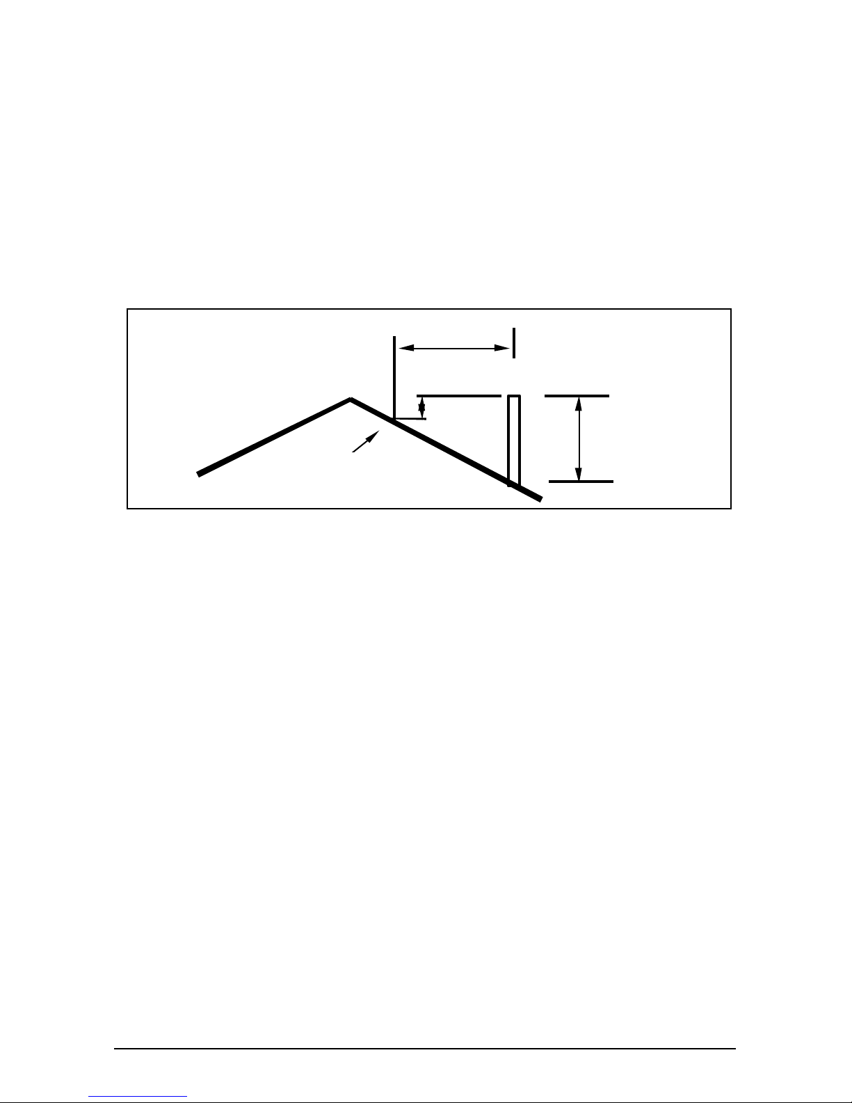
• The chimney should be high enough (at least four metres) and should end in a
zone that is clear of nearby buildings, trees or other obstacles. The rule of
thumb here is: 60 cm above the ridge of the roof. If the distance between the
ridge and the chimney measures more than three metres, see the dimensions
stipulated in the illustration below. Depending on the presence of nearby buildings or trees, the chimney should be higher.
3.1.2. Ventilation
The burning of wood, charcoal or gas involves oxygen consumption. It is of the utmost importance that the room in which the stove is installed should be sufficiently
ventilated.
Insufficient ventilation may disrupt the combustion process and cause the smoke
flow through the chimney to be interrupted, which may lead to smoke emissions
into the room.
If necessary, you can install a ventilation grille to provide a constant flow of fresh air
in the room. This precaution is particularly necessary in well-insulated rooms with
mechanical ventilation.
Ensure not to use other air-consuming appliances, such as heaters, cooking hoods,
bathroom ventilators, in the same room or in the house while the stove is burning;
or m ake sure to have an extra ventilation grill installed for these appliances.
If your stove is equipped with the (optional) connection set to feed combustion air
from outside the room, you do not need an additional air supply. However, ensure
sufficient ventilation of the room from which you supply air.
3.1.3. Floor, walls
A safe distance should be kept between the stove and combustible materials such as
wooden walls and furniture. This distance should be at least forty centimetres for
the side-wall (80 cm for 350CB3 and 360CB3 if glass panel is mounted) and 20 cm
for the back..
The appliance shall be installed on floors with an adequate load-bearing capacity.
Combustible floors require sufficient protection against radiant heat by means of a
fireproof protective plate. Rugs and carpets must be kept at a distance of at least
eighty centimetres from the fire.
min 0.5 m
3 m
min 1 m
highest point of the roof
within a distance of 3 m.
3 m
min 0.5 m
Page 6

350CB - 360CB - 350CB/SC - 350CB/3 - 360CB/3 6 03.27898.100
3.2. Preparing the stove
Please inspect the stove for damage caused during transport immediately after
delivery and notify your distributor in case there are any defects. Do not put the
stove into operation in the meantime.
In order to avoid damaging the stove during installation and to make handling of
the stove easier, it is recommended to remove previously all loose parts (fireresistant bricks, ashtray, ...) from the stove. Note the location of those parts while
removing them, so that you have no diffi culties in re-assembling the parts later on.
3.2.1. Assembling and installing the legs (if necessary)
Assemble both parts of the legs at the requested length using the
M6 bolts and rings. Tilt the stove backwards and mount the legs
on the pre-installed M8 bolts on the bottom plate of the stove.
3.2.2. Smoke outlet
Your stove is suitable for three connections: a top, a rear or a side
connection.
Select the type of connection that you want and break ou
the equivalent precarved opening, using the appropriate
tool. To do this you have to drill a 10mm hole in the middle
of the cover plate. Place the special tool with the bolt on
the inside of the cover plate en put the washer and the nut
on the bolt. Use a ring spanner and turn the nut until the
cover plate breaks out.
Remark: in case of enamelled stove, use a piece of cardboard (20cmx20cm) between the cover plate and the washer in order to protect yourself against enamel
fragments coming from the part.
Attach the connection collar, which is supplied
with the stove, to the fume outlet, using the two
fastening brackets on the inside and the nuts on
the outside (see sketch). Make sure that the
brackets correctly fit into their inserts at the left
and right hand side of the opening. For rear co nnection, break out the precarved plate on the heat shield. A pre-made opening can
always be closed again using a lid which is fixed by means of a steel strip and a
bolt (see sketch). Such a lid is available as spare part.
Seal with stopper paint or paste, which is delivered together with the stove.
3.2.3. Assembling the “cold handle”
Assemble the different parts of the handle,
i.e. a screw M8x50, a wooden handle and a
nut, as indicated on the sketch.
For some appliances, this handle can be
hooked on a handle holder which can be
mounted on the base plate of the stove,
near the left front leg (see sketch).
Page 7

350CB - 360CB - 350CB/SC 350CB/3 - 360CB/3 7 03.27898.100
3.2.4. Assembling the soapstone surrounding (only for 350 CB/SC)
1. Soapstone bottom
2. Soapstone top
3. Soapstone side plate
4. Connecting part
5. Connecting plate
6. Screw (D7991 m5x16)
7. Positioning pin
8. Positioning pin upper
9. Heat shield (cast iron)
10. Heat shield (Aluminum)
11. Cover
Page 8

350CB - 360CB - 350CB/SC - 350CB/3 - 360CB/3 8 03.27898.100
3.2.5. Assembling the side-panel
You can reduce the distance to combustible materials from 80 cm to 40 cm if
you change the galss-panel to a iron plate.
3.3. Finishing
When the stove is placed in the final position and hermetically connected to the
chimney, you can replace all of the loose parts.
Your stove is now ready for use.
Attention: never light a fire with the inner plates or refractory stones removed.
3.4. Packaging materials
Packaging materials should be disposed of in a responsible way and in accordance with governmental regulations.
Page 9

350CB - 360CB - 350CB/SC 350CB/3 - 360CB/3 9 03.27898.100
4. Instructions for use
4.1. Fuel
The only suitable fuel for this stove is wood. No other fuels are allowed to be burnt,
as they can inflict serious damage to your stove.
Do not burn any treated wood such as scrap wood, dyed wood, impregnated or pr eserved wood, plywood or chipboard. The fumes of these, as of synthetic materials,
old papers and household waste, are highly polluting for both your stove, your chimney, and for the environment. They also could cause chimney fires.
Wood
Hard woods, such as oak, birch- and fruit-trees, are the ideal fuels for your stove.
The wood must have dried for at least two years in a covered and well-ventilated
place. Split logs will dry faster. Dry wood should contain no more than twenty percent moisture.
Wet logs are unsuitable for burning, as they do not produce enough heat and all of
the energy is lost in the proc ess of evaporation. Moreover, the burning of wet wood
causes badly smelling gases to be released and a thick layer of tar will deposit on
the stove panels and in the chimney.
4.2. Lighting a fire
In order to create sufficient draught and to prevent smoke from being emitted into
the room, the chimney should be warm enough before lighting a fire. A cold chimney can be heated up by lighting a ball of paper above the fire plate.
To kindle the fire in the stove you can use paper and/or firelighters and small pieces
of wood.
Slightly open the door and turn the air slides wide open.
It is important that the kindled fire should burn intensely. You can then throw larger
pieces of wood onto the fire, and close the doors. When the fire has eventually stabilized and is glowing enough, you can close the lower air control. The fire is then
controlled by the upper air control.
4.3. Burning wood
Some items to watch, when burning wood: always keep the stove doors tightly closed.
Never leave the doors open when the fire is burning. Add extra fuel when necessary.
Never add too much fuel. The best is to fill up the combustion chamber for about half
(2 or 3 pieces of wood) and continue to fill up regularly. Always open the filling door
slowly and for a short space at a time. Before filling up, the charcoal bed should be
carefully spread open. Check whether the coals are glowing enough just behind the
log retainer, so that the added fuel will immediately catch fire. If necessary you can
open the fire up air control for a while. Remove the ashes (behind the ash hatch) when
the primary air inlet is obstructed too much.
Open stacking will make the logs burn very intensely, as the oxygen can easily reach
every part of the fire. This method of stacking is applied whe n burning wood for a
short while. Compact stacking will make the fire burn slower, as the air can only reach
the outer parts of the fire. This stacking method is best used when burning for a
longer while.
Page 10

350CB - 360CB - 350CB/SC - 350CB/3 - 360CB/3 10 03.27898.100
Low intensity fires cause tar and creosote to deposit in the chimney after a
long period of time. Tar and creosote
are highly combustible substances.
Thicker layers of these substances
might catch fire when the temperature
in the chimney increases suddenly and
steeply. Therefore it is necessary for
the fire to regularly burn very intensely,
so that thin layers of tar and creosote
immediately disappear.
Low intensity fires also cause tar to deposit on the stove panels and doors.
When it is not too cold outside it is better to let the stove burn intensely for just a
few hours a day.
4.4. Low heating (for devices suitable for continuous use)
To use the device as a 'continuous fire', you can select the primary and secondary air
scoops in such a way you get the right burning speed. Always make sure there's
enough glow on the heating bottom.
4.5. Ash removal
Underneath the stove you will find an ash removal grille. To remove the ashes the ash removal grille needs to be removed, so
that you can sweep the ashes into the ash pan with the small
shovel. You can then remove the ash pan out of the stove with
the ‘cold hand’. (see illustration)
When you burn logs of wood, there is no need to de-ash the stove each time, as only
little ashes are left after burning wood. Moreover, burning logs on a bed of ashes
promotes the combustion process.
4.6. Extinguishing the fire
Stop fuelling the fire and let it burn out.
Damping a fire by closing the air slides involves the release of noxious gases. You
should let the fire burn out and keep an eye on it as long as it is still glowing.
4.7. Weather conditions
Attention!
Mist and heavy fog will block the chimney's fume outlet and may lead to smoke
emission into the living room.
It is best not to use the stove under these weather conditions.
open stacking compact stacking
Page 11

350CB - 360CB - 350CB/SC 350CB/3 - 360CB/3 11 03.27898.100
5. Maintenance
It takes little effort to keep your stove in good condition.
Regularly check whether the sealing cord still closes the doors tightly enough.
The painted or enamelled cast iron mantle can be cleaned with a moist, soft cloth,
when it is almost cold. Make sure no aggressive, acid products get in touch with
enamelled parts.
Minor paint damage can be touched up with a can of spray paint. Your dealer can
supply you with the correct spray product. For enamel damage, small repair kits of
appropriate colour are available from your dealer.
During the first use after repainting your unit might give off some slight odour.
However, this will disappear quickly.
The glass can be cleaned with a number of glass cleaning products available from
your dealer. Your installer can also supply you with appropriate products. However,
never use abrasive or corrosive cleaning products.
A tight upper air slide can be adjusted with the two screws
just above the air intake holes on the front plate (see
sketch).
At the end of the heating season, seal off the chimney with a ball of paper. You can
then thoroughly clean the stove on the inside. If necessary, replace the sealing ropes
and use fire cement to fill up possible leaks. Remove the fire plate for better and
more thorough cleaning. The fire plate is fixed onto the back plate of the stove with
one bolt, visible from the outside. After having removed this bolt, you can easily
take the fire plate out of the stove. Eventually remove the refractory stones first.
You should have your chimney swept by an expert before the heating season begins.
It is also useful to check the chimney for soot during the heating season and to
check for blockage of the chimney flue prior to re -lighting after a prolonged shut
down period. Checking and maintaining the chimney is a statutory requirement.
When all of the above advice is heeded, you will be able to fully enjoy your stove.
Page 12

350CB - 360CB - 350CB/SC 350CB/3 - 360CB/3 12 03.27898.100
Annex 1: technical data sheet
Model / Modèle / Modell 350 CB(/3) 360 CB (/3) 350 CB/SC
Nominal heat output
6 kW
(max 8 kW)
8 kW
(max 10 kW)
6 kW
(max 8 kW)
Advised combustibles
Wood Wood Wood
Maximum length of logs
33 cm 40 cm 33 cm
Flue connection (diameter)
125 mm 125 mm 125 mm
Distance to adjacent
combustible materials
% CO 0.10 % 0.10 % 0.10 %
Efficiency 81 %
74 %
81 %
Flue gas mass flow
6,64 g/s 8,2 g/s 6,64 g/s
Flue gas temperature
242 °C 254 °C 242 °C
Minimum draught
0,12 mbar 0,10 mbar 0,12 mbar
Weight 95 kg 130 kg 130 kg
40 cm minimum (20 cm back)
Page 13

350CB - 360CB - 350CB/SC - 350CB/3 - 360CB/3 13 03.27898.100
Annex 2 : dimensions
350 CB/SC
Page 14

350CB - 360CB - 350CB/SC 350CB/3 - 360CB/3 14 03.27898.100
350 CB
350 CB/3
Page 15

350CB - 360CB - 350CB/SC - 350CB/3 - 360CB/3 15 03.27898.100
360 CB
360 CB/3
Page 16

350CB - 360CB - 350CB/SC 350CB/3 - 360CB/3 44 03.27898.100
DOVRE N.V. Tel : +32 (0) 14 65 91 91
Nijverheidsstraat 18 Fax : +32 (0) 14 65 90 09
B-2381 Weelde E-mail : info@dovre.be
___________________________________________________________
03.27898.100 0606
In het kader van een continue productverbetering, kunnen specificaties van het geleverde toestel afwijken
van de beschrijving in deze brochure, zonder voorafgaande kennisgeving.
Dans le cadre d’une amélioration constante des produits, les spécifications du produit livré peuvent différer
du contenu de ce document, sans avis préalable.
Due to continuous product improvement, specifications of the delivered product may differ from the content of this booklet, without further notice.
Im Rahmen kontinuerlicher Produktverbesserung, können Specifikationen des geliefertes Produktes von
den Beschreibungen in dieser Broschure abweichen.
CE-conformiteitsverklaring
Declaration de conformité CE
EC Declaration of conformity
Konformitätserklärung CE
Notified body: 1625
Wij,
Nous,
We,
Wir,
Dovre nv, Nijverheidsstraat 18, B2381 Weelde,
verklaren bij deze dat de houtkachel 350CB(3) en 360CB(3) conform zijn volgens de EN 13240.
déclarons que les poêles 350CB(3) et 360CB(3) sont conforme au norme EN
13240.
declare that the wood stoves 350CB(3) and 360CB(3) are in conformity with
the EN 13240.
Erklären daß das Produkt 350CB(3) / 360CB(3) entspricht EN 13240.
Weelde, 03.09.2005
 Loading...