

Page 1

INSTALLATIEVOORSCHRIFTENEN GEBRUIKSAANWIJZING
KACHEL
INSTALLATION INSTRUCTIONS AND OPERATING MANUAL
STOVE
INSTALLATION ET MODE D’EMPLOI
POELE
EINBAUANLEITUNG UND GEBRAUCHSANWEISUNG
FEUERSTÄTTE
INSTRUCCIONES DE INSTALACIÓN Y USO
ESTUFA
325MF
03.27107.100 - 02/2013
Page 2

Table of contents
Introduction 3
Declaration of conformity 3
Safety 4
Installation requirements 4
General 4
Chimney (flue) 4
Ventilationof the area 5
Floors and walls 5
Product description 6
Installation 6
General preparation 6
Preparing the outside air connection 8
Installing andconnecting 9
Use 9
First use 9
Fuel 9
Lighting 10
Burning wood 10
Burning brown coal briquettes 11
Burning anthracite coal 11
Controlling combustion air 11
Extinguishingthe fire 12
Removing ashes 12
Fog and mist 13
Solving problems 13
Maintenance 13
Chimney 13
Cleaning and other regular maintenance
activities 13
Exchangeparts 325MF 15
Appendix 1: Technical Data 16
Appendix 2: Dimensions 18
Appendix 3: Distance from combustible
material 20
Appendix 4: Diagnostic diagram 22
Index 23
2
Subjectto change becauseof technicalimprovements
Page 3

Introduction
Dear user,
In buying this DOVRE heating appliance, you have
chosen a high quality product. This product is part of a
new generation of energy-efficient and
environmentally-friendly heating appliances. These
appliances make optimum use of convection heat as
well as thermal radiation (radiant heat).
Your DOVRE appliance has been manufactured
with state-of-the-art production equipment. In the
unlikely event of a malfunction, you can always
rely on DOVRE for support and service.
The appliance should not be modified; please
always use original parts.
The appliance is intended for use in a living room. It
shouldbe connected hermetically to a wellfunctioning chimney.
We advise you have the appliance installed by an
authorized and competent installer.
DOVRE cannot be held liablefor any problems or
damage resulting from incorrect installation.
Observe the following safety regulations when
installing and using the appliance.
In this manual, you can read how the DOVRE heating
appliance can be installed, used and maintained
safely. Should you require additional informationor
technical data, or should you experience an
installation problem, please first contact yoursupplier.
© 2012 DOVRE NV
Declaration of
conformity
Notified body: 2013
The undersigned
Dovre nv, Nijverheidsstraat 18 B-2381 Weelde hereby
declares
that the 325MF wood stove has beenproduced in
accordance with EN 13240.
Weelde01-08-2012
Due to continuous product improvement, the supplied
appliance specifications may vary from the
description in this brochure without prior notice.
DOVRE N.V.
Nijverheidsstraat 18 Tel: +32 (0) 14 65 91 91
B-2381 Weelde Fax: +32 (0) 14 65 90 09
Belgium E-mail : info@dovre.be
Subjectto change becauseof technicalimprovements
3
Page 4
Safety
Please note: All safety regulations must be
compliedwith strictly.
Please read carefully the instructions supplied
with the appliance for installation, use and
maintenance, before using the appliance.
The appliance must be installed in accordance
with the laws and requirements of your
country.
All local regulations and the regulations relating
to national and European standards must be
observed when installing the appliance.
The appliance should preferably be installed by
an authorizedinstaller. Installers will be aware
of the applicable regulations andrequirements.
The appliance is designed for heating
purposes. All surfaces, includingthe glass and
connecting tube, can get very hot (over 100°C)!
For operation, use a so-called "cold hand" or an
oven glove.
Safety distances from flammable materials
must be adheredto strictly.
Don't place any curtains, clothes, laundry or
othercombustible materials on or nearthe
appliance.
Don't use flammable or explosive substances
near the appliance when it is in use.
Avoid a chimney fire by having the chimney
swept regularly. Never burn wood with the door
open.
In the case of a chimney fire: close all air inlets
of the appliance and alert the fire brigade.
If the glass in the appliance is brokenor
cracked, it must be replaced before you can
use the appliance again.
Make sure there is adequate ventilation in the
room where the appliance is installed. If
ventilation is insufficient, combustion will be
incomplete resulting in toxic gases being
producedand spread through the room. See
the chapter"Installation requirements" for more
information on ventilation.
Installation
requirements
General
The appliance must be connected tightly to a wellfunctioning chimney.
For the connection measurements: see the
appendix "Technical data".
Ask the fire brigade and/or yourinsurance
company about any specific requirements and
regulations.
Chimney (flue)
The flue or chimney is needed for:
Removal of combustion gases via natural draught.
As the warm air in the flue or chimney is lighter
than the outside air, it rises.
Air intake, needed for the combustion of fuel in the
appliance.
A poorly-functioningflue or chimney can cause smoke
to escape into the room when the door is opened.
Damage caused by smoke emissions into the room is
not coveredby the warranty.
Do not connect multiple appliances (such as a
boiler for central heating) to the same flue,
unless local or national regulations allow this.
In the event of two connections ensure that the
difference in height between the connections is
no less than 200 mm.
Ask your installerfor advice regarding the flue. Refer
to the European norm EN13384 for a correct
calculations for the flue.
The flue must satisfy the following requirements:
The flue or chimney must be made of fire-resistant
material, preferably ceramics or stainless steel.
The flue or chimney must be airtight and wellcleaned and guarantee sufficient draught.
4
Subjectto change becauseof technicalimprovements
Page 5

A draught/vacuum of 15-20Pa during normal
operationis ideal.
Starting from the flue spigot, the flue must run as
vertically as possible. Changes in direction and
horizontal pieces disrupt the outward flow of
combustion gases and may cause soot deposits.
To prevent combustion gases from cooling down
too much, which reduces the draught, ensure that
the interior diameter is not too big.
The flue or chimney should ideally have the same
diameter as the connection collar.
For the nominal diameter: see the appendix
"Technical data". If the smoke channel is well
insulated, the diameter may be slightly bigger
(upto 2x the section of the connection collar).
The section (area ) of the smoke channel must be
constant. Widersegments and (in particular)
narrowersegments disrupt the outward flow of
combustion gases.
When using a cover plate or exhaust hood: make
sure that the cover does not restrict the flue outlet
andthat the cap does not impede the outwardflow
of combustion gases.
The flue must end in a zone that is not affected by
surrounding buildings, trees or otherobstacles.
The flue outside the house must be insulated.
The chimney must be at least 4metres high.
As a ruleof thumb: 60cm above the ridge of the
roof.
If the ridge of the roof is more than 3metres away
from the flue: stick to the measurements in the
following figure. A = the highest point of the roof
within a distance of 3metres.
Ventilation of the area
For good combustion, the stove needs air (oxygen).
This air is supplied via adjustable air inlets from the
area in which the stove is installed.
The combustion will be incomplete in case of
insufficient ventilation, which results in toxic
gases being produced and spread through the
area.
As a ruleof thumb, the air supply should be 5,
5cm²/kW. Extra ventilation is needed when:
The stove is in an area that is well-insulated.
There is mechanical ventilation, for examplea
central extraction system or an extraction hoodin
an open kitchen.
You can provide extra ventilation by having a
ventilation louvre fitted on the outside wall.
Make sure that otherair consuming appliances (such
as tumble-driers, other heatingappliances or a
bathroom fan) have their own supply of outside air, or
areswitchedoff when you use the appliance.
You can also connect the appliance to an
outside airsupply. A connection kit is supplied
for this purpose. This makes additional
ventilation unnecessary.
Floors and walls
The flooron which the appliance is placed must have
sufficient bearing capacity. For the weight of the
appliance, see the appendix "Technical data".
Protect flammable flooring from heat radiation
by means of a fireproof protective plate. See
the appendix "Distance from combustible
material".
Remove combustible material such as
linoleum, carpets/rugs and similar materials
below the fireproof protective plate.
Keep sufficient distance between the
appliance and combustible materials such as
wooden walls and furniture.
The connecting tube also radiates heat. Ensure
that there is sufficient distance or a shield
between the connecting tubeand combustible
Subjectto change becauseof technicalimprovements
5
Page 6
material.
The rule of thumbfor a single-walled tubeis a
distance of 3x the diameter. If a lining shell is
fitted around the tube, a distance of 1x the
diameter is permissible.
Carpets andrugs must be at least 80cm away
from the fire.
Use a fireproof floorplate to protect a
flammable floor from any ash which may fall in
front of the stove. The protective plate must
comply with national standards.
For the dimensions of the fireproof protective
plate: see the appendix "Distance from
combustible material".
For further requirements in connection with fire
safety: see the appendix "Distance from
combustible material".
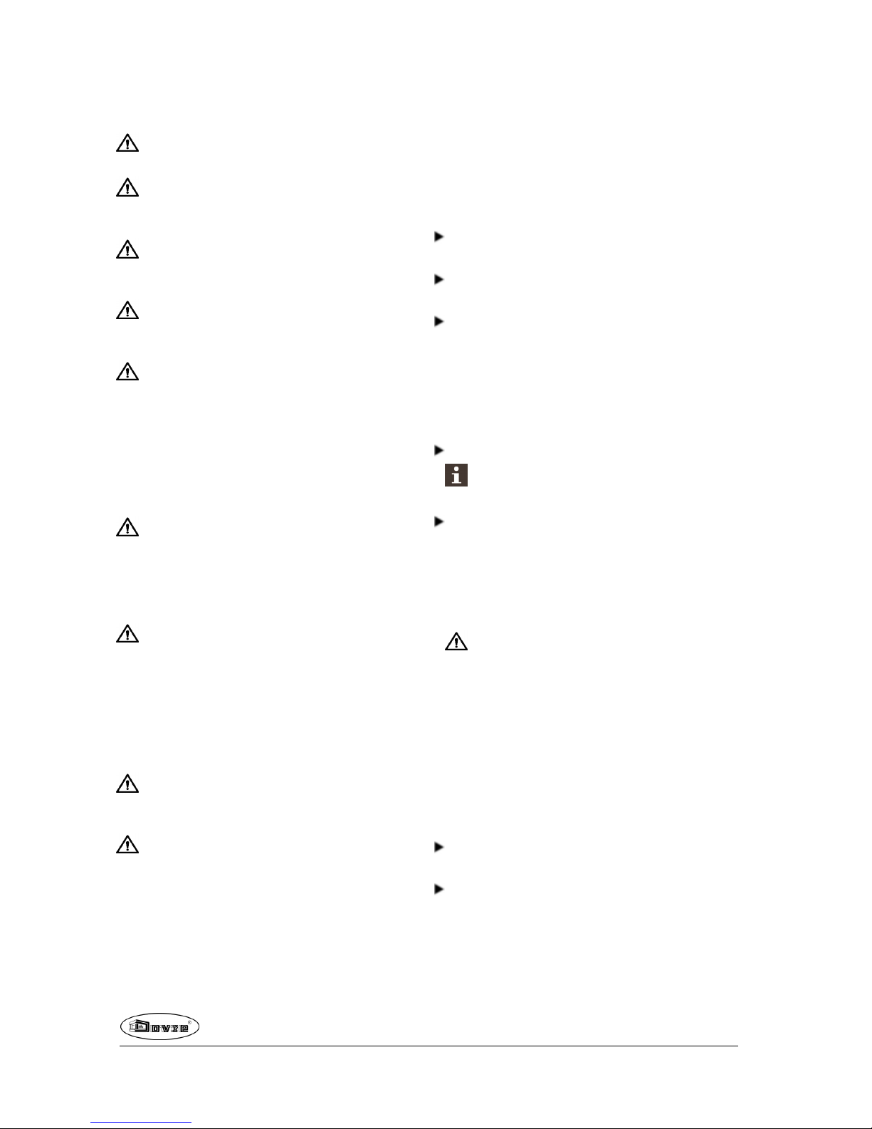
Product description
1. Top plate
2. Latch button
3. Bottom of the fire compartment
4. Door
5. Secondary air slide
6. Leg
7. Primary air slide
8. Riddling rod
Features of the appliance
The appliance is an entirely cast-irondesign with
modern combustion technology.
The airwash-system ensures prolonged clean
glass and so for an optimal view at the fire.
The appliance is suppliedwith the latch button
installed. As the latch button becomes warm during
use, a glove has beensupplied which you may use
to protect your hand.
The appliance is suitable for outside air supply
connection. The appliance comes standardwith a
connection kit necessary for this.
The appliance can be connected to the chimney at
the rear or at the upper side.
The appliance is suitable for the burning of wood,
brown coal briquettes and anthracite coal.
The appliance is suppliedwith a scraper for
removing excess ash.
The appliance is suppliedwith a separate handle,
the so-called"cold hand", to operate the riddling
rod.
Installation
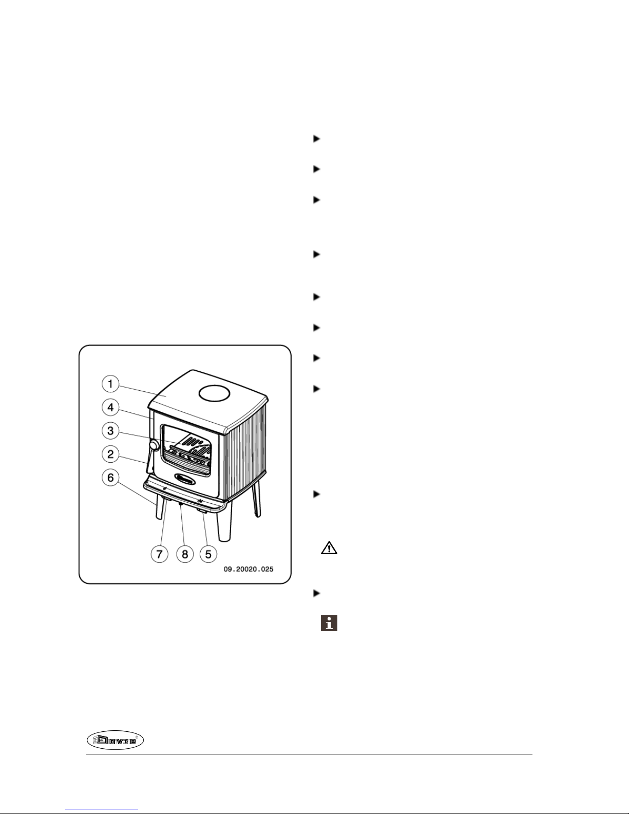
General preparation
Please check the appliance immediately after
delivery for damage causedduring transport or any
otherdamage or defects. Theappliance is attached
to the pallet with screws at the bottom.
If you detect damage caused duringtransport
or any other damage or defects, do not use the
appliance and notify the supplier.
Remove the removable parts from the appliance
before you start installing the appliance.
It is easier to move the appliance and to avoid
damage if the removable parts have been
removed.
6
Subjectto change becauseof technicalimprovements
Page 7
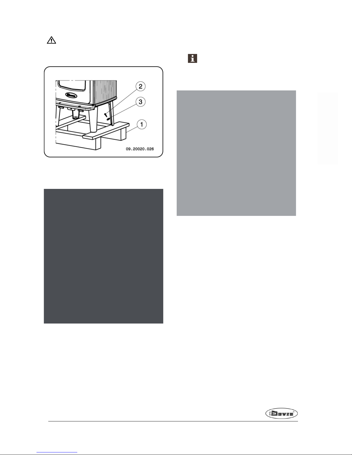
Note the location of the removableparts, so
that you can re-position the parts in the correct
place lateron.
1. Open the door; see the following figure.
2. Remove the fire-resistant inner plates; see the
following figure.
a. Remove the fire basket(3).
b. Take one of the innerplates (4) out of the
appliance.
c. Thenremove the baffle plate (5)
d. Remove the second inner plate (4)
e. Remove grid holder (2), the grate (6) and the
ash pan (7).
Chamotte inner plates areochrous on
delivery. They insulate the combustion
chamber, improving combustion and they
can withstandburning anthracite coals.
09.20020.101
Removable internal sections
2 grid holder
3 fire basket
4 inner plate on the left andright side
5 baffle plate
6 grate
7 ash pan
Connecting to the rear
1. Apply supplied fibre glass sealing tape (2)
measuring 10x3mm to the contact surface of the
connection collar (8).
2. Remove the protection plate from the back shield
with the assistance of a screwdriver; see following
figure.
Subjectto change becauseof technicalimprovements
7
Page 8
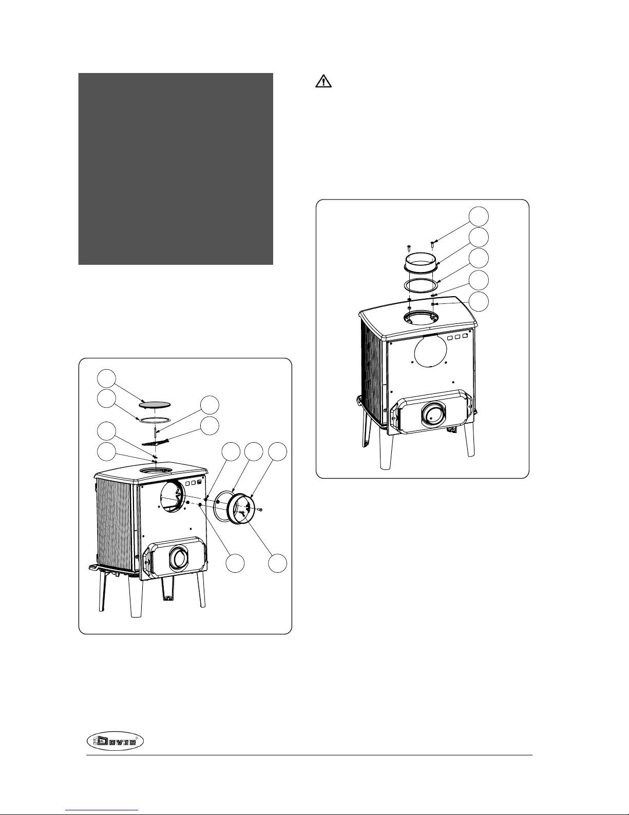
3. Remove the cover (1) from the back wall.
4. Install the connection collarto the back wall with
the materials.
5. Install the cover with mounting bracket (4)in the
top plate.
09-20008-006
3
4
5
6 7
9
2
1
2 8
10
Connect to top
On delivery, the connection at the rear is closed, so a
back cover does not need to be installed.
Because of the distance to the (combustible)
wall, the protection plate may not be removed in the
back shield.
1. Apply supplied fibre glass sealing tape (3)
measuring 10x3mm to the contact surface of the
connection collar (2).
2. Affix the connection collar to the top plate with the
materials supplied.
09-20008-007
1
2
3
4
5
Preparing the outside air
connection
If the appliance is installedin a room without sufficient
ventilation, you can install the connecting kit on the
appliance for the supply of outside air.
The airsupply tube is 100mm in diameter. If using a
smooth tube, it may be nolongerthan12metres long.
If accessories such as bends are used, the maximum
length (12metres)) must be reduced by 1metrefor
each accessory used.
8
Subjectto change becauseof technicalimprovements
Page 9

Outside air connection via the wall
1. Make an opening in the wall (see the appendix,
"Measurements", for the correct position of the
opening).
2. Close the air connection hermetically to the wall.
Installing and connecting
1. Position the stove in the correct place, and make
sure it is level.
2. Connect the appliance airtight to the flue
(chimney).
3. In the case of connection to outside air: connect
the outside air supply to the connector fitted to the
appliance.
4. Re-position all removed parts in the correct places
in the stove.
Never light a fire in the appliance without the
fireproof inner plates.
The appliance is now ready for use.
Use
First use
When you use the stove for the first time, make an
intense fire and keep it going for a good few hours.
This will cure the heat-resistant paint finish. This may
result in some smoke and odours. You could open
windows and doors for a while in the area in which the
stove is located.
Fuel
The appliance 325MF is a multi fuel stove.. This stove
is suitable for burningnatural wood; sawn and split
wood that is sufficiently dry. The appliance is also
suitable for the burning of brown coal briquettes and
anthracite coal.
Do not use other fuels, as they can cause serious
damage to the stove.
You are not allowed to use the following fuels, as they
pollute the environment and because they heavily soil
the appliance andflue, which may lead to a chimney
fire:
Treated wood, such as scrap wood, painted wood,
impregnated wood, preserved wood, plywoodand
chipboard.
Plastics, scrap paper and domestic waste.
Wood
Hardwood, such as oak, beech, birch and fruit tree
wood is the ideal fuel for your stove. This type of
wood burns slowly with calm flames. Softwood
contains more resins, burns faster and sparks
more.
Use seasoned wood that contains no more than
20% moisture. Thewoodshould have been
seasoned for at least 2 years.
Saw the wood to size and split it while it is still
fresh. Fresh wood is easier to split, and split wood
dries more easily. Store the wood under a roof
wherethe wind has free access.
Do not use damp wood. Damp logs do not produce
heat as all the energy is used in the evaporationof
moisture. This will result in a lot of smoke and soot
deposits on the stove doorand in the chimney. The
water vapour will condense in the stove and can
leak away through chinks in the stove, causing
black stains on the floor. It may also condense in
the chimney andform creosote. Creosote is a
highly flammable compound and may cause a
chimney fire.
Brown coal briquettes
Brown coal briquettes have approximately the same
burningcharacteristics as wood.
Ensurethere is a good charcoal bed before you
start burning brown coal briquettes.
For lighting the fireplace, follow the instructions in
the "Lighting" paragraph.
Anthracite coal
Anthracite coal is categorised on the basis of
characteristics, sometimes prescribedby law, such
as the percentage of volatile substances. The ash
content of anthracite coal is between 3% and 13%.
The lowerthe ash content, the higher the net heating
value and the less often you have to remove ash.
Subjectto change becauseof technicalimprovements
9
Page 10

Preferably use category A anthracite coal with a
low ash content.
Use the recommended size 12/22 or 20/30.
For lighting the fireplace, follow the instructions in
the "Lighting" paragraph.
Lighting
You can check whether the flue has sufficient draught
by lighting a ball of paper above the baffle plate. A cold
flue often has insufficient draught and consequently,
some smoke may escapeinto the room instead of up
the chimney. You can avoid this problem by lighting
the fire as described below.
1. Stack two layers of medium sized logs crosswise.
2. Stack two layers of kindling crosswise on top of
the logs.
3. Place a firelighter cube in the lower layerof
kindlingand light the cube according to the
instructions on the packaging.
4. Close the door of the appliance and open the
primary air inlet andthe secondary air inlet of the
appliance; see the following figure.
5. Allow the fire develop into a good blaze until there
is glowing bed of charcoal. You can then add fuel
andadjust the appliance, see the chapter "Stoking
with wood".
Open Closed
Burning wood
After you have followed the instructions for lighting :
1. Slowly open the stove door.
2. Spread the charcoal evenly across the bottom of
the stove base.
3. Stack a few logs on the charcoal.
Open stacking
If the logs are stacked openly, the wood will burn
quickly as the oxygen can reach each log easily. If
you want to use the stove for a short while, make an
open stack.
10
Subjectto change becauseof technicalimprovements
Page 11

Compact stacking
If the logs are stacked tightly, the wood will burn more
slowly as the oxygen can only reach some logs
easily. If you want to burn woodfor a longer period,
make a compact stack.
4. Close the door of the appliance.
5. Close the primary air inlet and leave the secondary
air inlet open.
Fill the appliance up to one third capacity.
Burning brown coal
briquettes
Brown coal briquettes burnin almost the same way as
wood. Using the primary air inlet, ensure sufficient
supply of air under the fire. For furtherinformationsee
the paragraph"Burning wood".
Burning brown coal briquettes creates a lot of ash.
Regularly remove excess ash. See the paragraph
"Removing ashes" for instructions.
For the properties and use of brown coal
briquettes: consult your brown coal briquettes
supplier or see the brown coal briquettes'
packaging.
After you have followed the instructions for lighting:
1. Slowly open the stove door.
2. Spread the charcoal evenly across the bottom of
the stove base.
3. Place the brown coal briquettes on the charcoal
bed.
4. Close the door.
5. Regularly remove ashes from the stove base by
riddling the grate. Use the cold handle to operate
the riddling rod.
Burning anthracite coal
Always close the secondary air slide when
burninganthracite coal.
Set the fuel choice air valve to the closed
position.
After you have followed the instructions for lighting:
1. Open the primary air slide completely.
2. Slowly open the stove door.
3. Spread the charcoal evenly across the bottom of
the stove base.
4. Spread a shovelful of coal on the charcoal bed and
wait with the next shovelful until the coals start to
glow.
5. Now addmore coal.
Be careful not to smother the fire by adding too
much coal at once.
You have added as much as you can once the
glow of the previous load is only just visible.
6. Close the door.
7. Allow the coals to burn well for a few minutes and
control the air supply using the primary air slider.
If the fire basket or the cast-iron plates start to
glow red you have overfed the fire.
8. Regularly remove ashes from the stove base
riddling the grate. Use the cold handle to operate
the riddling rod.
Controlling combustion air
The appliance has various features for air control; see
following figure.
Subjectto change becauseof technicalimprovements
11
Page 12

The primary air slide controls the air flow under the
grille (1).
The secondary air slide controls the air flow for the
glass (airwash-system) and air supply via the vents in
the back wall (2).
The back wall has permanent vents (3) below the
baffle plate that allow for post-combustion.
Advice
Never burn wood with an open door.
Regularly burn wood with intense roaring fires.
If you frequently have low intensity fires, tar
andcreosote may be deposited in the chimney
. Tar and creosote are highly combustible
substances. Thicker layers of these
substances may catch fire if the temperature in
the chimney increases suddenly. By allowing
the fire to burn very intensely regularly, layers
of tar and creosote will disappear.
Low intensity fires also cause tar deposits on
the stove window anddoor.
When the outside temperature is not very low,
it is better to burn wood intensely for a few
hours instead of having a low intensity fire for a
longperiodof time.
Control the air supply with the secondary air inlet.
The secondary air inlet not only supplies air to
the fire but to the glass as well, so that it does
not quickly become dirty.
Open the primary air inlet for the time being if the air
supply by the secondary air inlet is inadequate orif
you want to fan the fire.
It is better to add a small amount of logs regularly
than to add many logs at the same time.
Extinguishing the fire
Do not add fuel andjust let the fire go out. If a fire is
damped down by reducing the air supply, harmful
substances will be released. Forthis reason, the fire
shouldbe allowed to go out naturally. Keepan eye on
the fire until it has gone out. All air inlets can be closed
once the fire has diedcompletely.
Removing ashes
After the wood has beenburnt, a relatively small
amount of ashes is left over. This bed of ashes is a
good insulating layer for the stove base plate and
improves combustion. It is good to leave a thin layer
of ashes on the stove base plate.
However, the flow of air through the fire plate must not
be obstructed and no ash may be allowedto
accumulate behinda chamotte inner plate. Remove
the excess ash regularly.
After the brown coal briquettes and anthracite coal
has been burnt, a relatively large amount of ash is left
over. No ash may be allowed to accumulate
underneath the fire grate and the ash should never
reach the bottom of the grate. This will cause the grate
to overheat and be damaged.
12
Subjectto change becauseof technicalimprovements
Page 13

1. Use the riddling rod to free the grate (3) of excess
ashes.
If the appliance is till warm, use the "cold hand"
to operate the riddling rod.
2. Open the stove door.
3. Using the scraper (1) sweep the remaining ashes
through the grid.
4. Remove the ash pan (2)using the glove provided.
5. Empty the ash pan.
6. Put the ash panback into the appliance.
7. Close the door of the appliance.
Fog and mist
Fog and mist hinder the flow of flue gases through the
flue. Smoke can blow back andcause a stench. If it is
not strictly necessary, it is better not to use the stove
in foggy and misty weather.
Solving problems
Refer to the appendix "Diagnostic diagram" to resolve
any problems in using the stove.
Maintenance
Follow the maintenance instructions in this chapter to
keep the stove in good condition.
Chimney
In many countries, you are required by law to have
your chimney checked and maintained.
At the beginning of the heating season: have the
chimney swept by an expert.
Duringthe heating season and after the chimney
has not been used for a long time: have the
chimney checked for soot deposits.
After the heatingseason: seal off the chimney with
a ball of paper.
Cleaning and other regular
maintenance activities
Do not cleanthe stove when it is still warm.
Clean the exterior of the stove with a dry lint-free
cloth.
You can clean the stove interiorthoroughly at the end
of the heatingseason:
If necessary, first remove the fire-resistant inner
plates. See the chapter "Installation" for
instructions on removing andinstallingthe inner
plates.
If necessary, clean the air supply ducts.
Remove the baffle plate at the top of the appliance
andcleanit.
Subjectto change becauseof technicalimprovements
13
Page 14

Checking fire-resistant inner plates
The fire-resistant inner plates are consumables and
subject to wear . Check the fire-resistant inner plates
frequently and replace them when necessary.
See the chapter "Installation" for instructions on
removing andinstalling the inner plates.
The insulating vermiculite or chamotte inner
plates may develophairlinecracks, but this
does not affect theirperformance adversely.
Cast-iron inner plates last a long time if you
remove frequently the ash that can accumulate
behind them. If accumulated ash behind the
cast-iron plate is not removed, the plate will no
longer be able to dissipate the heat to the
surroundings andthis may cause the plate to
warp or crack.
Never use the stove without the fire-resistant
inner plates.
Cleaning glass
Dirt clings less easily to well-cleaned glass. Proceed
as follows:
1. Remove dust and loose soot with a dry cloth.
2. Clean the glass with stove glass cleaner:
a. Apply stove glass cleaner to a kitchen sponge,
rubdown the entire glass surface and give the
cleaning agent time to react.
b. Remove the dirt with a moist cloth or kitchen
tissue.
3. Clean the glass again with a normal glass cleaning
product.
4. Rub the glass clean with a dry cloth or kitchen
tissue.
Do not use abrasive or aggressive products to
clean the glass.
Wear household gloves to protect yourhands.
If the glass in the appliance is brokenor
cracked, it must be replaced before you can
use the appliance again.
Make sure that no stove window cleaner runs
between the glass and the cast-iron door.
Maintenance enamelled stove
Never clean the stove while it is still hot. The most
effective way to clean the enamelledsurface of the
stove is with a mild green soap andlukewarm water.
Use as little water as possible, rub the surface dry and
prevent the formation of rust. Wire wool or other
abrasives should never beused. Never place a kettle
directly onto an enamelled stove; use a stand to
prevent damage.
Lubrication
Although cast-iron is slightly self-lubricating, you will
still need to lubricate moving parts frequently.
Lubricate the moving parts (such as guide
systems,hingepins, latches and airslides) with
heat resistant grease that is available in the
specialist trade.
Touching up damaged paint
Small areas of damagedpaint finish can be touched
up with a spray can of special heat-resistant paint
finish available from yoursupplier.
Touching up the enamelled surface
Enamelling is a process carried out by traditional
methods, meaning that it is possible that small colour
differences and damage may occur. The appliances
undergo a visual inspection in the factory, that is to
say, the inspector looks at the surface for a period of
10 seconds from a distance of 1 metre.
Any damage that does not standout is regarded as
OK. A special heat-resistant paint is supplied with the
stove to touch up any minordamage caused during
transport.
Apply the heat-resistant paint in thin layers and leave
to dry well before using the appliance.
Some enamel colours are temperature-sensitive. It
can occur that the colour changes during use. The
original colour will return when the stove has cooled
down.
Checking the seal
Check whether the doorsealing rope is still in good
conditionand works well. The sealing rope is
subject to wear and will need to be replaced over
time.
14
Subjectto change becauseof technicalimprovements
Page 15

Check the appliance for air leaks. Close any
chinks with stove sealant.
Allow the sealant to harden fully before lighting
the stove, as any moisture in the sealant will
form bubbles, resulting in a new air leak.
Exchange parts 325MF
09.20020.101
Pos. Part number Description Quantity
2 03.56332.000 gridholder
1
3 03.77412.000 fire basket
1
4 03.77514.000
side inner plate 2
5 03.77515.000
baffle plate 1
6 03.61111.000 grate
1
7 03.05237.000 ash pan
1
Subjectto change becauseof technicalimprovements
15
Page 16

Appendix 1: Technical Data
Model 325MF 6kW
Nominal output 6 kW
Chimney connection (diameter) 125mm
Weight +/- 118 kg
Fuel
Wood
Brown coal
briquettes
Anthracite
coal
Fuel property, max. length wood, max.
format fuel
30 cm 3"-6"-7" 20-30
Mass flow of flue gases 4.1 g/s 4.4 g/s 4.0 g/s
Flue gas temperature measured in the
measurement section
325°C 306 °C 347 °C
Temperature measuredat the appliance
outlet
408°C 443 °C 395 °C
Minimum draught 12Pa 12 Pa 12 Pa
CO emission (13%O2) 0.10 % 0.10 % 0.04 %
NOx emission (13% O2) 100mg/Nm³ 156mg/Nm³ 106mg/Nm³
CnHm emission (13% O2) 119 mg/Nm³ 72 mg/Nm³ 25 mg/Nm³
Particulate emission 14 mg/Nm³ 10 mg/Nm³ 7.4 mg/Nm³
Efficiency 79 % 78.7 % 82.6 %
16
Subjectto change becauseof technicalimprovements
Page 17

Model 325MF 4.6kW
Nominal output 4.6 kW
Chimney connection (diameter) 125mm
Weight +/- 118 kg
Fuel
Wood
Brown coal
briquettes
Anthracite
coal
Fuel property, max. length wood, max.
format fuel
30 cm 3"-6"-7" 20-30
Mass flow of flue gases 4.9 g/s 4.1 g/s 3.6 g/s
Flue gas temperature measured in the
measurement section
248°C 308 °C 267 °C
Temperature measuredat the appliance
outlet
324°C 388 °C 345 °C
Minimum draught 12Pa 12 Pa 12 Pa
CO emission (13%O2) 0.17 % 0.12 % 0.17 %
NOx emission (13% O2) 114mg/Nm³ 178mg/Nm³ 98 mg/Nm³
CnHm emission (13% O2) 478 mg/Nm³ 47 mg/Nm³ 81 mg/Nm³
Particulate emission 25 mg/Nm³ 11 mg/Nm³ 6 mg/Nm³
Efficiency 75 % 76.1 % 81.9 %
Subjectto change becauseof technicalimprovements
17
Page 18

Appendix 2: Dimensions
325MF
18
Subjectto change becauseof technicalimprovements
Page 19

325MF (GB)
Subjectto change becauseof technicalimprovements
19
Page 20

Appendix 3: Distance from combustible material
325MF - Minimal distance in millimetres
1
2
09-20008-017
A Protective (insulated) connection pipe
1 Combustible material
2 Incombustible material, thickness 100 mm
Please note! To guarantee the flow of combustion air, whenno outside air connection is provided, the
distance from the outside airconnection collar to the wall must be at least 20 mm. The connection collar
may be removed where appropriate.
20
Subjectto change becauseof technicalimprovements
Page 21

325MF - Dimensions of fireproof protective plate
A
B B
09-20002-004
Minimal dimensions of fireproof protective plate
A (mm) B (mm)
Din 18891 500 300
Germany 500 300
Finland 400 100
Norway 300 100
Subjectto change becauseof technicalimprovements
21
Page 22

Appendix 4: Diagnostic diagram
Problem
Wood will not stay lit
Gives off insufficient heat
Smoke emissions into the room when adding wood
Fire in stove is too intense, is hard to adjust
Deposit on the glass
Possible cause Possible solution
Insufficient draught
A cold flue usuallyfailsto create sufficient draught. Follow the
instructionsfor lightingin the "Use" chapter; open a window.
Wood too damp Use wood with no more than 20%moisture.
Logs too large
Use smallpieces of kindling.Use splitlogs no larger than 30 cm in
circumference.
Wood stacked incorrectly
Stackthe logs in a way that allows adequate air flow between the
logs(open stacking, see "Burning wood")
Chimney does not work properly
Check whether the chimneymeets the requirements: at least4
metres high, right diameter, wellinsulated, smooth inside, not too
many bends, no obstructions inchimney (bird's nest, too much soot
deposit), hermeticallytight (no chinks).
Chimney stack incorrect Sufficientlyhigh above the roof, no obstacles in the vicinity
Air inlets setincorrectly Open the air inlets completely.
Stove connected to the chimney
incorrectly
Connection shouldbe hermeticallytight.
Vacuum in area in whichthe stove is
installed
Switch off extraction systems.
Insufficient supplyof fresh air
Provide an adequate air supply; if necessary use outside air
connection.
Adverse weather conditions?
Inversion (reversed air flow in chimney
because of a high outsidetemperature),
extreme wind speeds
We recommend you don't use the appliance in the case of inversion.
If required, installan extra hood on the flue to increase the draught.
Draught inthe living room
Avoiddraught inthe living room, do not place the appliance near a
door or heating air ducts.
Flames touch the glass
Make sure the wood isnot positioned too close to the glass. Slide the
primary air inletcover closer to the "Closed" position.
Stove is leaking air Check the door seals and stove joints.
22
Subjectto change becauseof technicalimprovements
Page 23

Subjectto change becauseof technicalimprovements
23
Index
A
Adding fuel 12
Adding wood
smoke emissions into the room 22
Air control 11
Air inlets 10
Air leak 14
Air supply for fire 12
Anthracite coal 9
Ashes
remove 12
B
Bearing capacity of floor 5
Brown coal
ash 11
burning 11
Brown coal briquettes 9
Burning
adding fuel 11
anthracite coal 11
brown coal briquettes 11
Burning wood 10
addfuel 12
adding logs 10
appliance is hard to adjust 22
fire is too intense 22
insufficient heat 13, 22
C
Carpet 5
Cast ironinner plates 7
Chamotte
fire-resistant 7
Chimney
connection diameter 16-17
connection to 9
height 5
sweep 13
Chinks in appliance 14
Clean
glass 14
Cleaning
appliance 13
Coal
ash content 9
Combustible material
distance from 20
Connection
dimensions 18
Connection collar for connection to chimney 8
Connection to chimney
at top 8
top 8
Connection to supply of outside air 8
Control air supply 12
Control of air 11
Cover on flue 5
Creosote 12
D
Damage 6
Damp wood 9
Dimensions 18
Door
open 7
sealingrope 14
Draught 16-17
Drying wood 9
E
Efficiency 16-17
Enamel
maintenance 14
F
Filling height 11
Finishingcoat, maintenance 14
Fire
extinguishing 12
lighting 10
Fire-resistant innerplates
maintenance 14
remove 7
Fire going out 12
Fire safety
distance from combustible material 20
floor 5
furniture 5
walls 5
Page 24

Fireproof inner plates
warning 9
Floors
bearingcapacity 5
fire safety 5
Flue
maintenance 13
requirements 4
Flue gas
mass flow 16-17
temperature 16-17
Fog, do not burn wood 13
Fuel
adding 12
adding wood 11
anthracite coal 9
brown coal 9
brown coal briquettes 9
necessary amount 13
suitable 9
unsuitable 9
wood 9
G
Glass
clean 14
deposit 22
H
Heat, insufficient 13
Heat,insufficient 22
Hood on the flue 5
I
Innerplates
chamotte 7
Innerplates, fire-resistant
remove 7
Installation
dimensions 18
K
Kindled fire 10
Kindling 22
L
Lighting 10
Lubricant 14
Lubricate 14
M
Maintenance
chimney 13
clean glass 14
cleaning the appliance 13
enamel 14
fire-resistant inner plates 14
lubrication 14
sealing 14
Mist, do not burn wood 13
N
Nominal output 13, 16-17
O
Open
door 7
Outside air intake
connection to 9
P
Paint finish 9
Particulate emission 16-17
Parts, removable 6
Prevent a chimney fire 12
Primary air inlet 10
R
Removable parts 6
Removal of ashes 12
Remove
fire-resistant inner plates 7
Remove ashes 12
Removing ash
brown coal 11
S
Screens
clean 14
deposit 22
Sealing ropefor door 14
Secondary air inlet 10
Smoke
on first use 9
Smoke emissions into the room 4, 22
24
Subjectto change becauseof technicalimprovements
Page 25

Subjectto change becauseof technicalimprovements
25
Softwood 9
Solving problems 13, 22
Stacking logs 10
Storingwood 9
Stove window cleaner 14
Suitable fuel 9
Supply of outside air 5, 8
Sweep chimney 13
T
Tar 12
Temperature 16-17
U
Unsuitable fuel 9
V
Ventilation 5
connect supply of outside air 8
ruleof thumb 5
Ventilationlouvre 5
Vermiculite inner plates 7
W
Walls
fire safety 5
Warning
chimney fire 4, 9, 12
combustible materials 4
fireproof inner plates 9
glass brokenor cracked 4, 14
hot surface 4
regulations 4
stove window cleaner 14
terms and conditions for insurance 4
ventilation 4-5
Weatherconditions, do not burnwood 13
Weight 16-17
Wood 9
damp 9
does not keepburning 22
drying 9
right sort 9
storing 9
 Loading...