

Dovre 2900GL, 2900GDC, 2900RGD, 2900RGC, 2900GD Installation Instructions And Operating Manual
Page 1
2900 1 03.27896.100
INSTALLATIEVOORSCHRIFTEN EN GEBRUIKSAANWIJZING
INSTALLATION ET MODE D’EMPLOI
INSTALLATION INSTRUCTIONS AND OPERATING MANUAL
EINBAUANLEITUNG UND GEBRAUCHSANWEISUNG
INBOUWHAARD / FOYER
FIREPLACE / KAMINEINSATZ
2900-serie
2900GL 2900GD(C) 2900RGD(C)
Page 2

2900 2 03.27896.100
Foreword
The Installation Manual and Operators Instructions must accompany this appliance.
As well as instructions for installation and information about use, you will also find
advice concerning safety and maintenance.
Please read this booklet carefull y before installation and before firing the unit.
Save this booklet and pass to any subsequent user who can also profit by it.
1. Introduction
Your DOVRE purchase has made you the owner of a high quality product that symbolizes a new generation of energy-saving and ecologically safe heaters, producing
convection heat as well as radiant heat with optimum efficiency. Through the application of a revolutionary combustion concept DOVRE heaters achieve astonishing
results in full compliance with strict environmental and safety norms. Also, you will
be enjoying the lovely sight of the fire blazing in the stove.
Our heaters are produced in accordance with ISO 9002, using state-of-the-art production means.
In the unlikely event of a malfunction, you can always rely on DOVRE’s after-sales
service.
This heater is designed to be installed in a living room and to be hermetically connected to a flue (chimney).
If the stove is professionally installed, connected to a well-functioning chimney and
sufficiently ventilated, you can take the long -term and trouble -free functioning of
your heater for granted.
Please consult an expert when installing and connecting the heater. The manufacturer cannot be held liable for problems caused by faulty installation.
2. Safety
The heating unit is best installed, commissioned, and checked by a competent installer who is aware of national and local legislation.
The heater is designed to heat a room, which means that all surfaces, including the
front glass, can get very hot (> 100 °C).
Please do not place any curtains, clothes, laundry, furniture or other combustible
materials on or near the heater.
It is advised to make a fire in the stove with the highest possible intensity right after
it is installed, so as to cure the heat-resistant paint finish. This may involve some
odour production, which will however disappear after a while.
It is necessary to maintain and regularly clean the stove and the chimney for the
stove to function safely and for a long period of time. Please follow the cleaning instructions in the chapter concerned.
In case of a chimney fire, immediately close all air intake vents of the appliance and
alert the fireman.
Broken glass should be replaced before using the heater again.
The stove is specifically designed for burning ce rtain kinds of fuels. In the technical
specifications under cover you can find detailed information concerning this topic. It
is absolutely prohibited to burn fuels other than these, as this may damage your
heater. Moreover, it is ecologically harmful.
Page 3

2900 3 03.27896.100
3. Installation guideline
3.1. Preparatory measures
The fireplace should be hermetically connected to a well-functioning chimney, sufficiently enclosed to keep combustible materials (floor and walls) at a distance, and
should be installed in a room with sufficient ventilation.
Please inform about national or local norms and regulations concerning this subject.
Your distributor will give you the necessary advice.
You can also consult the fire department and/or an insurance company about specific demands or regulations.
Please read the technical specifications under cover in this manual before installing
the appliance.
3.1.1. The chimney
The chimney (the flue) has a double function:
• It draws air, that is necessary for good combustion, into the stove.
• It functions as an exhaust pipe for combustion gases via thermal or natural
draught. Thermal draught is caused by the difference in heat between the air in and outside the flue. The heated air in the flue is lighter than the colder air ou tside the flue and consequently rises up, along with the combustion gases. Natural draught is caused by environmental phenomena, such as wind.
It is prohibited to connect several heaters to one chimney (for instance the central
heating boiler), unless local or national regulations allow this.
Please check which chimney is to be used for the stove you purchased and whether
your chimney is appropriate for this specific usage. You should consider an expert's
opinion on this matter.
The chimney should meet the following conditions:
• The flue should be made of fireproof material. Ceramic or stainless steel is re-
commended.
• The chimney should be airtight and thoroughly cleaned and should guarantee a
sufficient draught (a draught or negative pressure of 15 to 20 Pa is ideal under
normal circumstances).
• It should run as vertically as possible. Changes in direction or horizontal seg-
ments will disrupt the smoke flow and may cause soot to cumulate inside the
flue (and clog the flue!).
• The chimney's inside dimensions must not be too large in order to prevent the
smoke from cooling off too much. For recommended chimney dimensions, see
the technical specification under cover. Larger dimensions can be used if the flue
is well insulated.
• The flue's diameter should be the same throughout its whole length. Wider, or
especially narrower segments will disrupt the smoke flow and are best avoided.
Page 4
2900 4 03.27896.100
The same is true for a cover plate or exhaust hood on top of the chimney. The
exhaust hood must not narrow the chimney's outlet and should be designed in a
way that wind will not hinder, but promote the smoke flow.
• Especially if the flue runs through unheated rooms or outside the house, further
insulation is necessary. Metal chimneys, or parts of the chimney outside heated
rooms should always have double-walled, insulated flues. The part of the chimney outside the roof should always be insulated.
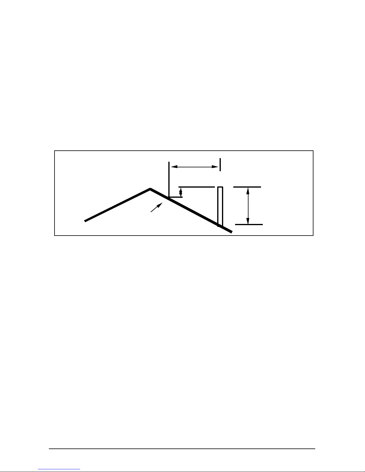
• The chimney should be high enough (at least four metres) and should end in a
zone that is clear of nearby buildings, trees or other obstacles. The rule of
thumb here is: 60 cm above the ridge of the roof. If the distance between the
ridge and the chimney measures more than three metres, see the dimensions
stipulated in the illustration below. Depending on the presence of nearby buildings or trees, the chimney should be higher.
3.1.2. Ventilation
The burning of wood, charcoal or gas involves oxygen consumption. It is of the utmost importance that the room in which the stove is installed should be sufficiently
ventilated.
Insufficient ventilation may disrupt the combustion process and cause the smoke
flow through the chimney to be interrupted, which may lead to smoke emissions
into the room. Mainly in case of a fireplace, together with the combustion gases, lots
of room air will be extracted through the chimney; that makes supply of sufficient
fresh air and ventilation extremely important.
If necessary, you can install a ventilation grille to provide a constant flow of fresh air
in the room. This precaution is particularly necessary in well-insulated rooms with
mechanical ventilation.
The DOVRE fireplace has been designed to produce most heat by means of convection. Heat is mainly transmitted through the back panel, the lateral panels, and the
smoke dome. Both the material (cast iron) and shape (increased heating surface by
means of corrugation) improve heat transmission to the surrounding air. As this air
is heated, it will rise and a natural hot air flow, i.e. convection, will develop. Up to
your choice, that hot air may be led to the same room or to another room.
For optimal heating and leading the convection air, the airflow must not encounter
any obstacles. Hence, it is important that there is enough space between the fireplace and the surrounding material, and that the inlet and outlet area of convection
air are sufficiently large.
min 0.5 m
3 m
min 1 m
highest point of the roof
within a distance of 3 m.
3 m
min 0.5 m
Page 5
2900 5 03.27896.100
Convection air may be led to arrive from both
the room and outside (other room, cellar, exterior) to the bottom side of the fireplace. In case
convection air is supplied (directly or indirectly)
from outside, it may also be useful as a supply
of fresh air for combustion.
At any rate, assure proper home air management and sufficient air supply into the room.
Ensure not to use other air-consuming appliances, such as heaters, cooking hoods, bathroom ventilators, in the same room or in the
house while the stove is burning; or make sure
to have an extra ventilation grille installed for
these appliances.
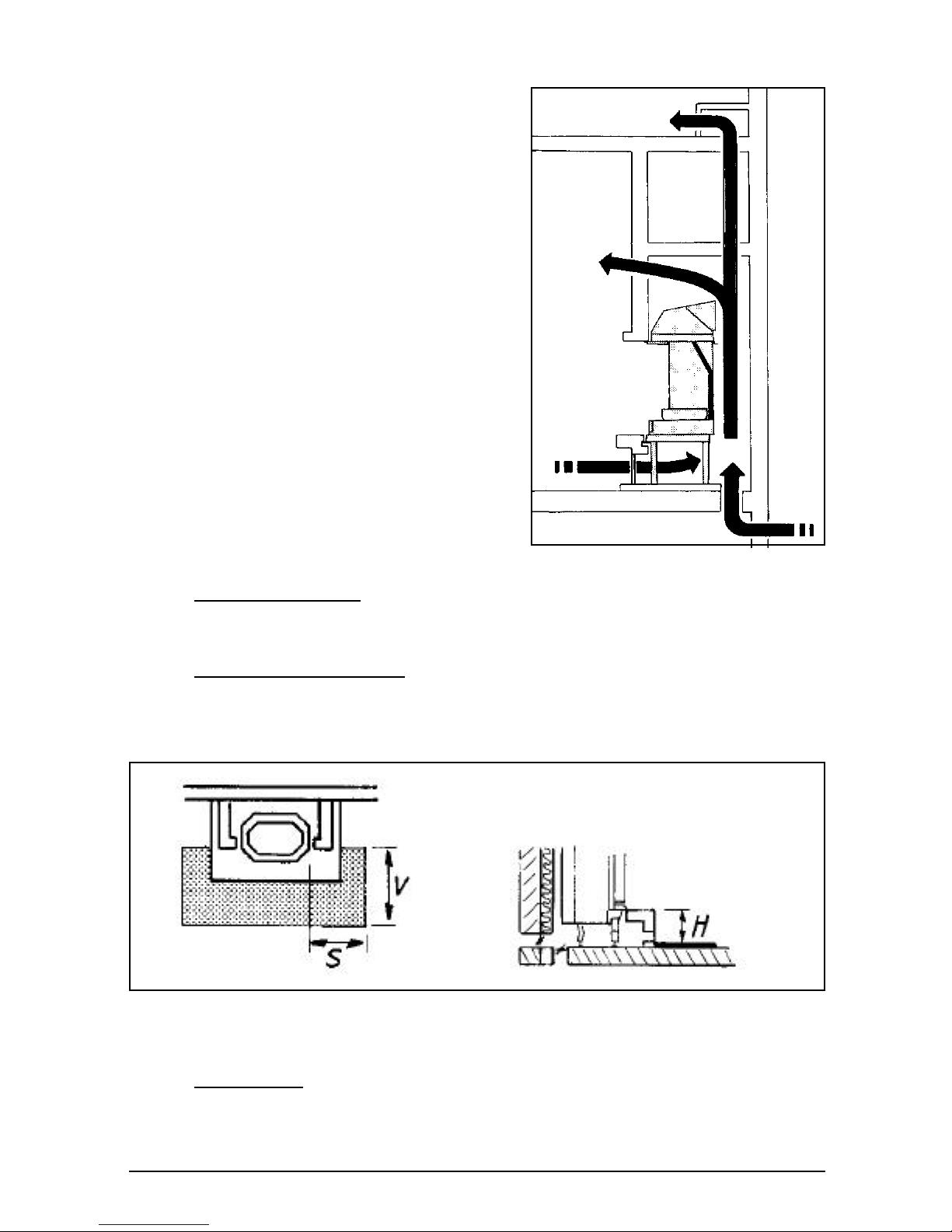
3.1.3. Floor, walls
Combustible material must be sufficiently protected. The floor under the fireplace and the
walls around it must not contain elec tric wires.
The appliance shall be installed on floors with
an adequate load-bearing capacity.
Under the appliance
Under the appliance, any combustible material must be removed or specially
shielded by means of a 6 cm concrete slab and 10 cm insulation.
Floor round the appliance
A floor made of combustible material must be properly shielded in the following
areas:
Front: height of the lower part of the fire chamber + 30 cm, but 60 cm at least.
Sides: height of the lower part of the fire chamber + 20 cm, but 40 cm at least.
Walls, ceiling
Combustible walls behind, next to, or above the fireplace must be shielded with at
least a 10 cm stone or brick wall and 10 cm insulation. Fireproof materials should be
covered with at least 6 cm insulation.
V > H + 30 > 60
S > H + 20 > 40
Page 6
2900 6 03.27896.100
3.2. Preparation
Please inspect the fireplace for damage caused during transport immediately after
delivery and notify your distributor in case there are any defects. Do not put the appliance into operation in the meantime.
In order to avoid damaging the fireplace during installation and to make its handling
easier, it is recommended to remove previously all loose parts (fire-resistant bricks,
grille, ashtray, ...) from the stove. Note the location of those parts while removing
them, so that you have no difficulties in re-assembling the parts later on.
See picture 1 for how to handle the aplliance for transport.
See picture 2 for loosing the screws for tansport-securty.
3.2.1. Assembly of the legs (see picture 3)
Fix the adjustment bolts under the legs. These will allow to adjust the fireplace
level.
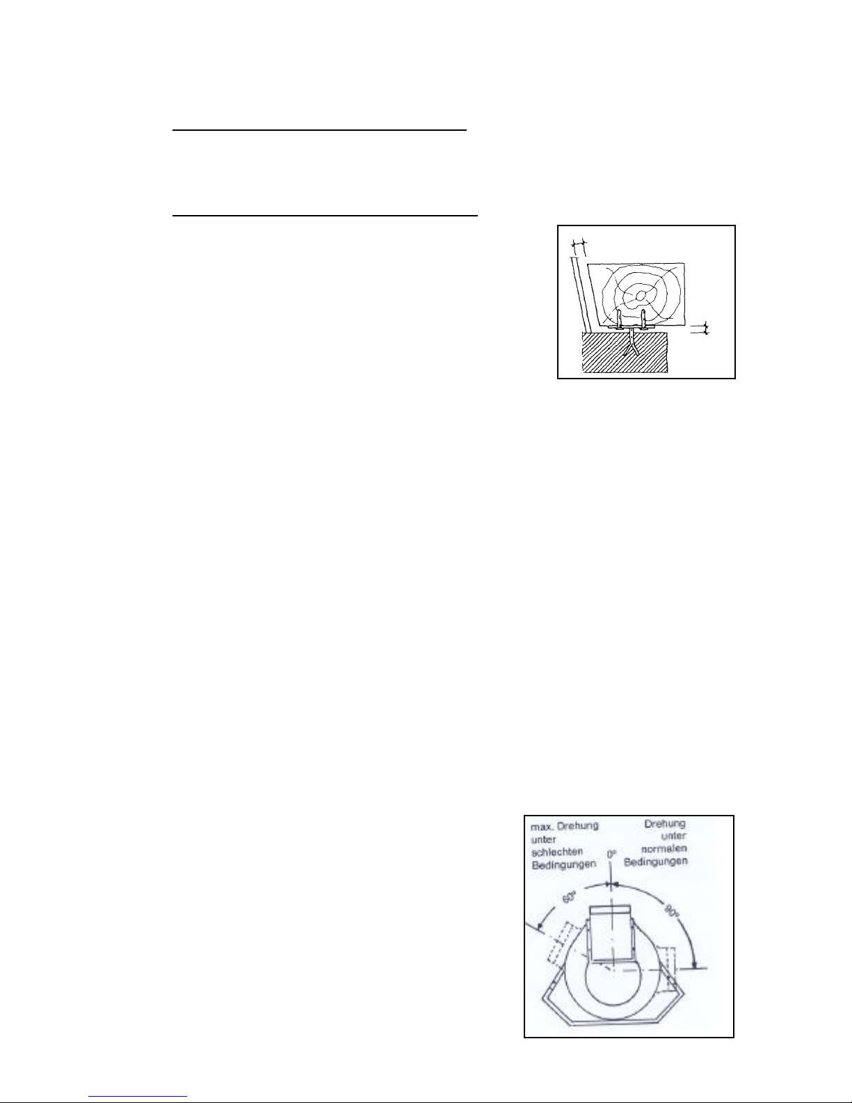
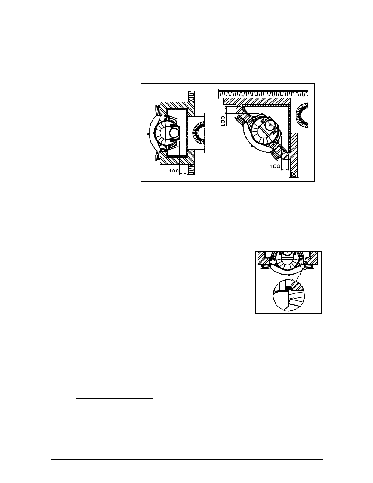
3.2.2. Assembly of the smoke dome and of the flue collar
The smoke dome must be fixed to the top of the device and attached by means of the clamps supplied.
Assure proper sealing by means of the kit or paste supplied.
It is recommended to install the smoke dome with its
exhaust backwards. In case of proper draft, it may be
turned up to 90° to the left or to the right if required
for installation. In case of lower draft, an angle of
maximum 60° is recommended.
The flue collar can be installed either horizontally or
vertically. Fix the flue collar on the smoke dome. Assure proper sealing with kit or paste.
3.1.4. Combustible material round the fireplace
Within the radiation area of the fireplace
Assure a distance of at least 80 cm between the opening of the fireplace and combustible material. That distance may be reduced to 40 cm if the combustible material is sufficiently shielded and well ventilated.
Outside the radiation area of the fireplace
Assure a distance of at least 5 cm between the mantle built
around the fireplace and combustible material. A small surface contact between combustible material and the mantle
(e.g. wall cladding) is allowed if the mantle of the fireplace
is sufficiently insulated.
A wooden ornamental rafter must not be installed within
the radiation area of the fire. Outside the radiation area,
there must always be a ventilation gap of 1 cm all around
to prevent heat from building up (see picture).
No combustible material must be present within 50 cm from the convection outlet
areas.
min 1 cm
min 1 cm
Page 7
2900 7 03.27896.100
3.3. Installation of the fireplace
3.3.1. Positioning and connection
Put the fireplace at proper height. Make sure that it is stable and level and that the
side panels are perpendic ular to the bottom
plate. Put the fireplace far
enough from the walls, so
that minimum 5 cm of free
air passage remains between the back of the fireplace and the wall after
adding the necessary insulation.
Make an airtight connection between fireplace and
chimney, according to
good pra ctice.
Before further installation of the fireplace, check for sufficient draft in the chimney
and for proper connection between the smoke duct and the appliance.
For that purpose, you can light a small intense fire with paper and small dry kindle.
In case of a brick smoke duct, wait until the duct is dry enough.
3.3.2. Mounting
Start with the masonry round the base of the fireplace. In that
masonry, the air supply grids (optional) will be installed. Minimum air supply opening is 250 cm². The grids may be installed
on all sides.
It is important that air flows freely into the convection chamber. If you use an air vent (to convey outside air into the convection chamber), remember to build in the adjustment knob.
It is recommended to cover the inner side of the convection
chamber with extra reflecting insulation material. That prevents loss of heat radiation to outside walls or adjacent rooms, as well as deterioration of any inside wall insulation.
Make sure that the doors of the hearth move freely over the plate in front of the fireplace.
Continue building the chimney up to the smoke dome. Assure a gap of at least 2
mm between the fireplace and the masonry to allow for dilatation of the fireplace. If
necessary, use heat-resistant strips.
Upper structure support
The masonry over the fireplace must not rest on the fireplace. That is why a support
is used. Between the steel support and the smoke dome, you must leave a free
space of at least 3 mm. That will prevent tensions in the material that might tear the
upper structure. The steel support may rest on the side structure or be attached to
the wall by means of threaded rods.
Page 8

2900 8 03.27896.100
Convection chamber:
The convection chamber topside must be airtight. For that purpose, you can use a
cover of steel, concrete, or any other fire-resistant material, and put extra insulation
on top of it. Make sure that the cover is well horizontally placed.
The cover must be installed at 30 cm at least above the smoke dome. The outlet
grids must be installed straight under that cover. Make sure that convection outlet
area is big enough: minimum 500 cm².
In the convection chamber no combustible material must be used. Make sure that,
when using other auxiliary material such as steel, it will not function as a heat
bridge.
The picture on the next page shows an example of fireplace installation within
combustible
3.4. Finishing
When the appliance is installed in the right place, its connection with the chimney
made airtight, and the masonry mantle completely mounted, all loose parts are installed in the appliance.
Your fireplace is now ready to be used.
Depending on the materials used for mounting, it is recommended to wait for some
time until all masonry is dry before lighting a fire.
Attention: never light a fire with the inner plates or refractory stones removed.
3.5. Packaging materials
Packaging materials should be disposed of in a responsible way and in accordance
with governmental regulations.
Page 9

2900 9 03.27896.100
Example of fireplace installation within combustible material
Chimney
Refractory cement or special
conncetor
Insulation
(min 10 cm)
Fireproof wall
(min 10 cm )
Combustible
wall
Convection air
Fresh air inlet
Fireproof floor Combustible
floor
Convection air
inlet
Insulation (if
necessary))
Convection air
outlet
Opening
against eventu-
al pressure
builup
Stainless steel
pipe
IInsulati-
Combustible
ceiling
Fireproof ceiling
Cover plate
Min 1.5 cm
Page 10

2900 10 03.27896.100
4. Instructions for use
4.1. Fuel
The only suitable fuel for this stove is wood. No other fuels are allowed to be burnt,
as they can inflict serious damage to your stove.
Do not burn any treated wood either, such as scrap wood, dyed wood, impregnated
or preserved wood, plywood or chipboard. The fumes of these, as of synthetic materials, old papers and household waste, are highly polluting for both your stove and
your chimney, and for the environment. They also could cause chimney fires.
Wood
Hard woods, such as oak, birch- and fruit-trees, are the ideal fuels for your stove.
The wood must have dried for at least two years in a covered and well-ventilated
place. Split logs will dry faster. Dry wood should contain no more than twenty percent moisture.
Wet logs are unsuitable for burning, as they do not produce enough heat and all of
the energy is lost in the proc ess of evaporation. Moreover, the burning of wet wood
causes badly smelling gases to be released and a thick layer of tar will deposit on
the stove panels and in the chimney.
4.2. Burning wood
In order to create sufficient draught and to prevent smoke from emanating into your
living room, the chimney should be warm enough before lighting a fire. A cold chimney can be heated up by lighting a ball of paper above the fire plate.
To kindle the fire in the stove you can use paper and/or firelighters and small pieces
of wood.
Slightly open the door and pull the air slides wide open. See the illustration opposite
on how to use the air slides.
It is important that the kindled fire should burn intensely. You can then throw larger
pieces of wood onto the fire, and close the doors. When the fire has eventually stabilized and is glowing enough, you can put the logs.
Add extra fuel when necessary. Never add too much fuel. It is best to fill the stove
for one third and to top it up on a regular basis.
Always open the filling door slowly. Before filling up, the charcoal bed should be
carefully spread open. Check whether the coals are glowing enough just behind the
log retainer, so that the added fuel will immediately catch fire. If necessary you can
open the lower air slide for a while.
Open stacking will make the logs burn very intensely, as the oxygen can easily reach
every part of the fire. This method of stacking is applied when burning wood for a
short while. Compact stacking will make the fire burn slower, as the air can only
reach the outer parts of the fire. This stacking method is best used when burning for
a longer while.
Page 11

2900 11 03.27896.100
Low intensity fires cause tar and
creosote to deposit in the chimney after a long period of time.
Tar and creosote are highly combustible substances. Thicker
layers of these su bstances might
catch fire when the temperature
in the chimney increases suddenly and steeply. Therefore it is
necessary for the fire to regularly burn very intensely, so that
thin layers of tar and creosote
immediately disa ppear.
Low intensity fires also cause tar to deposit on the stove panels and doors.
When it is not too cold outside it is better to let the stove burn intensely for just a
few hours a day.
The fireplace can burn with either open or closed doors. When the doors are left
open, it is recommended to use a spark screen.
4.3. Ash removal
The ashtray must be emptied before the ashes reach the lower edge of the combustion grid. With the cold handle supplied, you can tilt the grid upwards and remove
the ashtray from the device. (See picture 6-8.)
Relatively speaking, burning wood produces little ash and it will not be necessary to
remove it each time daily. Moreover, wood burns better on a bed of ash.
4.4.. Extinguishing the fire
Stop fuelling the fire and let it burn out.
Damping a fire by closing the air slides involves the release of noxious gases. You
should let the fire burn out and keep an eye on it as long as it is still glowing.
4.5. Weather conditions
Attention!
Mist and heavy fog will block the chimney's smoke outlet and may lead to smoke
emissions into the living room.
It is best not to use the fireplace under these weather conditions.
open stacking compact stacking
Page 12

2900 12 03.27896.100
5. Maintenance
It takes only little effort to keep your appliance in good condition.
Regularly check whether the sealing cord still closes the doors tightly enough.
Minor paint damage can be touched up with a can of spray paint. Your dealer can
supply yo u with the correct spray product.
During the first use after repainting your unit might give off some slight odour.
However, this will disappear quickly.
The glass can be cleaned with a number of glass cleaning products available on the
market. Your installer can also supply you with appropriate products. However,
never use abrasive or corrosive cleaning products.
At the end of the heating season, seal off the chimney with a ball of paper. You can
then thoroughly clean the stove on the inside.
If necessary, replace the sealing ropes and use fire cement to fill up possible leaks.
Remove the fireplate for better and more thorough cleaning.
To remove the doors, disassemble the hinges as shown.
You should have your chimney swept by an expert before the heating season begins.
It is useful to check the chimney for soot during the heating season as well. Checking and maintaining the chimney is a statutory requirement.
Desambly of the guidance-system
See pictures 12-16.
When all of the above advice is heeded, you will be able to fully enjoy your stove.
Installation of damper in 2900GL
Insert the damper between the smoke chamber and the connecting flange (see Illustration 1 for how to insert the damper through the smoke chamber). Insert the
damper first at the top between the smoke bell and the connection flange (A), by
holding the damper at the bottom to the right (Illustration 17), and then insert the
damper at the bottom in the seating (B).
Insert the rod through the air spoiler and connect it to the damper (Illustration 20)
The damper ca n still be adjusted with the screw at the end of the rod; when you turn
the screw inwards, the damper does not close completely when the door is closed
(Illustration 22).
Page 13

2900 13 03.27896.100
Installation of damper in 2900(R)GD(C)
Insert the damper between the smoke chamber and the connecting flange (see Illustration 1 for how to insert the damper through the smoke chamber). Insert the
damper first at the top between the smoke bell and the connection flange (A), by
holding the damper at the bottom to the right (Illustration 2), and then insert the
damper at the bottom in the seating (B).
Connect the rod to the damper (Illustration 17).
Then install the flame shield with the rod going through the hole of the flame shield
(Illustration 20).
The connecting piece (C on Illustration 24) is inserted over the rod and everything is
hooked over the bolt on the tumbler (E in Illustration 24).
The adjustment of the damper is carried out with the nut (D on Illustration 24) on the
rod; if you turn the nut down towards the connecting piece then the damper closes
more completely. (The adjustments are best made before the flame shield is installed).
Page 14

2900 14 03.27896.100
Bijlage 1: technische gegevens / Annexe 1: données techniques /
Annex1: technical data sheet / Anlage 1: technischen Daten
Model / Modèle / Modell 2900(R)GD(C) 2900GL
Nominaal vermogen
Puissance nominale
Nominal heat output
Nominalleistung
11 kW
11 kW
Aanbevolen brandstoffen
Combustibles conseillés
Advised combustibles
Empfohlene Brennstoffe
Hout
Bois
Wood
Holz
Bruinkool
lignite
Browncoal
Braunkohl
Hout
Bois
Wood
Holz
Hout
Bois
Wood
Holz
Bruinkool
lignite
Browncoal
Braunkohl
Hout
Bois
Wood
Holz
Deuren
Portes
Doors
Feuerraum
Gesloten
Fermé
Closed
Geschlossen
Gesloten
Fermé
Closed
Geschlossen
Open
Ouvert
Open
Geöffnet
Gesloten
Fermé
Closed
Geschlossen
Gesloten
Fermé
Closed
Geschlossen
Open
Ouvert
Open
Geöffnet
Schoorsteenaansluiting
Raccordement cheminée
Flue connection
Schornsteinanschluss
200 mm
200 mm
Massadebiet van rookgassen
Débit des fumées
Flue gas mass flow
Abgasmassenstrom)
14.5 g/s
15.4 g/s
46.2 g/s
9.5 g/s
9.2 g/s
37.2 g/s
Rookgastemperatuur
Température des fumées
Flue gas temperature
Abgasstutzentemperatuur
410 °C
405 °C
220 °C
313 °C
314 °C
167 °C
Minimum trek
Dépression minimal
Minimum draught
Mindesförderdruck
0.12 mbar
0.12 mbar
0.08 mbar
0.13 mbar
0.13 mbar
0.08 mbar
Gewicht / Poids / Weight
130 kg
75kg
Page 15

2900 15 03.27896.100
1 2
3 4
5 6
Page 16

2900 16 03.27896.100
7 8
9 10
11 12
Page 17

2900 17 03.27896.100
13
13
14 15
17 18
Û
A
Ý
B
14
15 16
Page 18

2900 18 03.27896.100
D —
/
C
\
E
Ù A
Ù B
19 20
21 22
23 24
Page 19

2900 19 03.27896.100
Annex 2 : dimensions
Anlage 2 : Abmessungen
Bijlage 2 : afmetingen
Annexe 2 : dimensions
2900GL
Page 20

2900 20 03.27896.100
2900GD
2900GDC
Page 21

2900 21 03.27896.100
2900RGDC
2900RGDC
Page 22

2900 22 03.27896.100
DOVRE N.V. Tel : +32 (0) 14 65 91 91
Nijverheidsstraat 18 Fax : +32 (0) 14 65 90 09
B-2381 Weelde E-mail : info@dovre.be
___________________________________________________________
03.27896.100 0545
In het kader van een continue productverbetering, kunnen specificaties van het geleverde toestel afwijken
van de beschrijving in deze brochure, zonder voorafgaande kennisgeving.
Dans le cadre d’une amélioration constante des produits, les spécifications du produit livré peuvent différer
du contenu de ce document, sans avis préalable.
Due to continuous product improvement, specifications of the delivered product may differ from the content of this booklet, without further notice.
Im Rahmen kontinuerlicher Produktverbesserung, können Specifikationen des geliefertes Produktes von
den Beschreibungen in dieser Broschure abweichen.
CE-conformiteitsverklaring
Declaration de conformité CE
EC Declaration of conformity
Konformitätserklärung CE
Notified body: 1641
Wij,
Nous,
We,
Wir,
Dovre nv Nijverheidsstraat 18 B2381 Weelde
verklaren bij deze dat de inbouwhaard 2900-serie conform is volgens de EN
13229.
déclarons que le foyer 2900-serie est conforme au norme EN 13229.
declare that the fireplace 2900-serie is in conformity with the EN 13229.
Erklären daß das Produkt 2900-serie entspricht EN 13229.
Weelde, 17.11.2005
 Loading...