

Page 1
INSTALLATIEVOORSCHRIFTENEN GEBRUIKSAANWIJZING
Inzethaard
INSTALLATION INSTRUCTIONS AND OPERATING MANUAL
Fireplace insert
INSTALLATION ET MODE D’EMPLOI
Foyer encastrable
EINBAUANLEITUNG UND GEBRAUCHSANWEISUNG
Einsatzofen
INSTRUCCIONES DE INSTALACIÓN Y USO
Chimenea
ISTRUZIONI PER L'INSTALLAZIONE E L'USO
Inserto
03.27883.300 - 09/2013
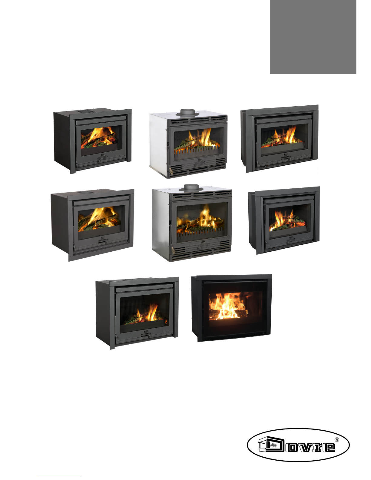
2020, 2200, 2210,
2220, 2500, 2510,
2520 en 2620
Page 2
2
Wijzigingen op grond van technische verbeteringen voorbehouden
Inhoudsopgave
Inleiding 3
Prestatieverklaring 4
Veiligheid 9
Installatiecondities 9
Algemeen 9
Schoorsteen 9
Ventilatie van de ruimte 10
Vloer en wanden 11
Productbeschrijving 11
Installatie 13
Voorbereiding 13
Inbouwen in een bestaandeschouw 14
Inbouwen in een nieuwe schouw 15
Uitwendige kader monteren 17
Gebruik 18
Eerste gebruik 18
Brandstof 18
Aanmaken 19
Stoken met hout 20
Stoken met bruinkoolbriketten 21
Stoken met antracietkolen 21
Regeling van de verbrandingslucht 22
Doven van het vuur 22
Ontassen 22
Nevel en mist 23
Eventueleproblemen 23
Onderhoud 23
Schoorsteen 23
Schoonmaken en ander regelmatig onderhoud23
Bijlage 1: Technische gegevens 26
Bijlage 2: Aansluitschema's 28
Bijlage 3: Afmetingen 31
Bijlage 4: Afstand tot brandbaar materiaal 40
Index 42
Page 3

Wijzigingen op grond van technische verbeteringen voorbehouden
3
Inleiding
Geachte gebruiker,
Met de aankoop van dit verwarmingstoestel van
DOVRE heeft u gekozen voor eenkwaliteitsproduct.
Dit product maakt deel uit van een nieuwe generatie
energiezuinige en milieuvriendelijke verwarmingstoestellen. Deze toestellen maken optimaal
gebruik van zowel convectiewarmte als stralingswarmte.
Uw DOVRE toestel is geproduceerdmet de
modernste productiemiddelen. Mocht er onverhoopt toch iets mankeren aanuw toestel, dan kunt
u altijd een beroepdoen op de DOVRE service.
Het toestel mag niet gewijzigd worden; gebruik
steeds origineleonderdelen.
Het toestel is bedoeld voor plaatsing in eenwoonruimte. Het moet hermetisch worden aangesloten
op een goedwerkende schoorsteen.
Wij adviseren u het toestel te laten installerendoor
eenbevoegd installateur.
DOVRE kan niet aansprakelijk wordengesteld wordenvoorproblemen of schade dooreen onjuiste
installatie.
Bij installatie en gebruik moeten dehiernabeschreven veiligheidsvoorschriften in acht worden genomen.
In deze handleidingleest u hoe u het DOVRE verwarmingstoestel op een veilige manierinstalleert,
gebruikt en onderhoudt. Als u aanvullende informatie
of technische gegevens wilt of een installatie-probleem heeft, neemt u dan eerst contact op met uw
leverancier.
© 2013 DOVRE NV
Page 4

Prestatieverklaring
Volgens de bouwproductenverordening 305/2011
Nr. 102-CPR-2013
1. Unieke identificatiecode van het producttype:
2020S / 2200 / 2210/ 2220
2. Type-, partij- of serienummer, dan wel een ander identificatiemiddel voor het bouwproduct, zoals
voorgeschreven in artikel 11, lid 4:
Uniek serienummer.
3. Beoogde gebruiken van het bouwproduct, overeenkomstig de toepasselijke geharmoniseerde technische specificatie, zoals door de fabrikant bepaald:
Kachel voorvaste brandstof zonder productie van warm water volgens EN 13240.
4. Naam, geregistreerde handelsnaam of geregistreerd handelsmerk en contactadres van de fabrikant,
zoals voorgeschreven in artikel 11, lid 5:
Dovre N.V. Nijverheidsstraat 18 2381 Weelde Belgium.
5. Indien van toepassing, naam en contactadres van de gemachtigde wiens mandaat de in artikel 12,
lid 2, vermelde taken bestrijkt:
-
6. Het systeem of de systemen voor de beoordeling en verificatie van de prestatiebestendigheid van
bouwproduct, vermeld in bijlage V:
Systeem 3
7. Indien de prestatieverklaring betrekking heeft op een bouwproduct dat onder een geharmoniseerde
norm valt:
De aangesteldeinstantie RRF, geregistreerd onderhet nummer1625, heeft onder systeem 3 een type-keur
uitgevoerd en heeft het testrapport nr 2905903 verstrekt.
8. Indien de prestatieverklaring betrekking heeft op een bouwproduct waarvoor een Europese technische beoordeling is afgegeven:
-
4
Wijzigingen op grond van technische verbeteringen voorbehouden
Page 5
Wijzigingen op grond van technische verbeteringen voorbehouden
5
9. Aangegeven prestatie:
De geharmoniseerde norm EN 13240 :2001/A2 :2004/AC :2007
Essentiële karakteristieken
Prestaties
Hout
Prestaties
Bruinkool
Prestaties
olen
Brandveiligheid
Vuurbestendigheid A1 A1 A1
Afstandtot brandbaarmateriaal
(minimale afstand in mm)
Achterkant: 100
Zijkant: 100
Achterkant: 100
Zijkant: 100
Achterkant: 100
Zijkant: 100
Risico van uitvallende gloeiende deeltjes Conform Conform Conform
Emissie van verbrandingsproducten
CO: 0,10%
(13%O2)
CO: 0,06%
(13%O2)
CO: 0,04%
(13%O2)
Oppervlaktetemperatuur Conform Conform Conform
Elektrische veiligheid - - -
Gemakkelijk te reinigen Conform Conform Conform
Maximale werkingsdruk - - -
Rookgastemperatuurbij nominaal vermogen 295°C 289°C 272°C
Mechachanise weerstand
(gewicht dragen van schoorsteen)
Niet bepaald Niet bepaald Niet bepaald
Nominaal vermogen 7 kW 7 kW 8 kW
Rendement 78.3 % 75,4 % 76,4 %
10. De prestaties van het in de punten 1 en 2 omschreven product zijn conform de in punt 9 aangegeven prestaties.
Deze prestatieverklaring wordt verstrekt onder de exclusieve verantwoordelijkheid van de in punt 4 vermelde fabrikant:
26/08/2013 Weelde
Tom Gehem
CEO
Page 6

Volgens de bouwproductenverordening 305/2011
Nr. 105-CPR-2013
1. Unieke identificatiecode van het producttype:
2500 / 2510/ 2520/ 2620
2. Type-, partij- of serienummer, dan wel een ander identificatiemiddel voor het bouwproduct, zoals
voorgeschreven in artikel 11, lid 4:
Uniek serienummer.
3. Beoogde gebruiken van het bouwproduct, overeenkomstig de toepasselijke geharmoniseerde technische specificatie, zoals door de fabrikant bepaald:
Kachel voorvaste brandstof zonder productie van warm water volgens EN 13240.
4. Naam, geregistreerde handelsnaam of geregistreerd handelsmerk en contactadres van de fabrikant,
zoals voorgeschreven in artikel 11, lid 5:
Dovre N.V. Nijverheidsstraat 18 2381 Weelde Belgium.
5. Indien van toepassing, naam en contactadres van de gemachtigde wiens mandaat de in artikel 12,
lid 2, vermelde taken bestrijkt:
-
6. Het systeem of de systemen voor de beoordeling en verificatie van de prestatiebestendigheid van
bouwproduct, vermeld in bijlage V:
Systeem 3
7. Indien de prestatieverklaring betrekking heeft op een bouwproduct dat onder een geharmoniseerde
norm valt:
De aangesteldeinstantie RRF, geregistreerd onderhet nummer1625, heeft onder systeem 3 een type-keur
uitgevoerd en heeft het testrapport nr 2905904 verstrekt.
8. Indien de prestatieverklaring betrekking heeft op een bouwproduct waarvoor een Europese technische beoordeling is afgegeven:
-
6
Wijzigingen op grond van technische verbeteringen voorbehouden
Page 7

Wijzigingen op grond van technische verbeteringen voorbehouden
7
9. Aangegeven prestatie:
De geharmoniseerde norm EN 13240 :2001/A2 :2004/AC :2007
Essentiële karakteristieken
Prestaties
Hout
Prestaties
Bruinkool
Prestaties
Kolen
Brandveiligheid
Vuurbestendigheid A1 A1 A1
Afstandtot brandbaarmateriaal
(minimale afstand in mm)
Achterkant: 100
Zijkant: 100
Achterkant: 100
Zijkant: 100
Achterkant: 100
Zijkant: 100
Risico van uitvallende gloeiende deeltjes Conform Conform Conform
Emissie van verbrandingsproducten
CO: 0,10%
(13%O2)
CO: 0,09%
(13%O2)
CO: 0,05%
(13%O2)
Oppervlaktetemperatuur Conform Conform Conform
Elektrische veiligheid - - -
Gemakkelijk te reinigen Conform Conform Conform
Maximale werkingsdruk - - -
Rookgastemperatuurbij nominaal vermogen 264°C 318°C 314°C
Mechachanise weerstand
(gewicht dragen van schoorsteen)
Niet bepaald Niet bepaald Niet bepaald
Nominaal vermogen 10 kW 10 kW 10 kW
Rendement 80,0 % 76,4 % 79,0 %
10. De prestaties van het in de punten 1 en 2 omschreven product zijn conform de in punt 9 aangegeven prestaties.
Deze prestatieverklaring wordt verstrekt onder de exclusieve verantwoordelijkheid van de in punt 4 vermelde fabrikant:
26/08/2013 Weelde
Tom Gehem
CEO
Page 8

In het kadervan een continue productverbetering, kunnen specificaties van het geleverde toestel afwijken van de
beschrijving in deze brochure, zonder voorafgaande kennisgeving.
DOVRE N.V.
Nijverheidsstraat 18 Tel : +32 (0) 14 65 91 91
B-2381 Weelde Fax : +32 (0) 1465 90 09
België E-mail : info@dovre.be
8
Wijzigingen op grond van technische verbeteringen voorbehouden
Page 9
Wijzigingen op grond van technische verbeteringen voorbehouden
9
Veiligheid
Let op! Alle veiligheidsvoorschriften moeten
strikt worden nageleefd.
Lees aandachtig de instructies voor installatie,
gebruik en onderhoud die met het toestel zijn
meegeleverd, voordat u het toestel in gebruik
neemt.
Het toestel moet wordengeïnstalleerd overeenkomstig de wetgevingen voorschriften van
uw land.
Alle lokale bepalingenen de bepalingendie
betrekking hebben op nationale en Europese
normen moeten worden nageleefd bij het installeren van het toestel.
Laat het toestel bij voorkeur installeren door
eenbevoegd installateur. Deze is op de hoogte
van de geldende bepalingen en voorschriften.
Het toestel is ontworpen voorverwarmingsdoeleinden. Alle oppervlaktes, inclusief het glas en de aansluitbuis kunnen zeer
heet worden(meer dan 100°C)! Gebruik voor
de bediening een 'koude hand' of eenhittebestendigehandschoen.
Zorg voor voldoende afscherming als jonge kinderen, mindervaliden en ouderen zich in de
nabijheidvan het toestel bevinden.
Veiligheidsafstanden tot brandbaarmateriaal
moeten strikt worden aangehouden.
Plaats geengordijnen, kleren, wasgoedof
andere brandbare materialen bovenopof in de
nabijheidvan het toestel.
Gebruik tijdens het gebruik van uw toestel
geen licht ontvlambare of explosieve stoffen in
de nabijheid van het toestel.
Voorkom schoorsteenbranddoor regelmatig de
betreffendeschoorsteen te latenreinigen.
Stook het toestel nooit met open deur.
Bij schoorsteenbrand: sluit de luchtinlaten van
het toestel en waarschuw de brandweer.
Als het glas van het toestel is gebroken of
gebarsten, moet dit glas wordenvervangen
voordat u het toestel opnieuw in gebruik neemt.
Zorg voor voldoende ventilatie van de ruimte
waar het toestel wordt geplaatst. Bij onvoldoendeventilatie vindt onvolledige verbranding
plaats, waardoorzich giftige gassen in de
ruimte kunnen verspreiden. Zie het hoofdstuk
"Installatiecondities" voor meer informatie over
ventilatie.
Installatiecondities
Algemeen
Het toestel moet wordenaangesloten op eengoed
werkende schoorsteen.
Voor de aansluitmaten: zie de bijlage "Technische
gegevens".
Informeer bij de brandweer en/of verzekeringsmaatschappij naar eventuele specifieke
vereisten en voorschriften.
Schoorsteen
De schoorsteenis nodigvoor:
Het afvoerenvan deverbrandingsgassen door
natuurlijke trek.
De warme lucht in de schoorsteen is lichter
dande buitenlucht en stijgt daarom.
Het aanzuigen van lucht, nodig voor de verbranding
van de brandstof in het toestel.
Een niet goed werkende schoorsteen kan tijdens het
openenvan de deur rookterugslag geven. Schade
Page 10
10
Wijzigingen op grond van technische verbeteringen voorbehouden
ontstaan door rookterugslag is uitgesloten van garantie.
Sluit niet meerdere toestellen(bijvoorbeeld ook
nogeen centraleverwarmingsketel) op
dezelfde schoorsteen aan, tenzij lokale of nationale regelgeving hierin voorziet. Zorg in ieder
geval bij twee aansluitingen dat het hoogteverschil tussen de aansluitingen minimaal
200mm bedraagt.
Vraag uw installateurom advies over de schoorsteen.
Raadpleegde Europese norm EN13384 voor een
juiste berekening van de schoorsteen.
De schoorsteenmoet aan de volgende voorwaarden
voldoen:
De schoorsteenmoet gemaakt zijn van vuurvast
materiaal, bij voorkeur keramiek of roestvrij staal.
De schoorsteenmoet luchtdicht en goed gereinigd
zijn en voldoende trek garanderen.
Een trek/onderdruk van 15-20Pa tijdens normale belasting is ideaal.
De schoorsteenmoet - vertrekkend van de uitgang
van het toestel - zo verticaal mogelijk lopen. Richtingsveranderingen en horizontale stukken verstoren de afvoer van verbrandingsgassen en
veroorzakenmogelijk roetophoping.
De binnenmaten mogen niet te groot zijn, om te
voorkomen dat de verbrandingsgassen te sterk
afkoelen waardoorde trek minder wordt.
De schoorsteenmoet bij voorkeur dezelfde diameter hebben als de aansluitkraag.
Voor de nominale diameter: zie de bijlage
"Technische gegevens". Als het rookkanaal
goed is geïsoleerd, kan de diametereventueel
wat groterzijn (maximaal tweemaal de sectie
van de aansluitkraag).
De sectie (oppervlakte) van het rookkanaal moet
constant zijn. Verwijdingen en (vooral)vernauwingenverstoren de afvoer van verbrandingsgassen.
Bij toepassing van een regenkap/afvoerkap op de
schoorsteen: let eropdat de kap niet de uitmonding
van de schoorsteen vernauwt en dat de kap niet de
afvoer van verbrandingsgassen belemmert.
De schoorsteenmoet uitmonden in een zonedie
niet wordt verstoord door omliggendegebouwen,
vlakbijstaande bomen of andere hindernissen.
Het schoorsteengedeelte buiten de woning moet
geïsoleerd zijn.
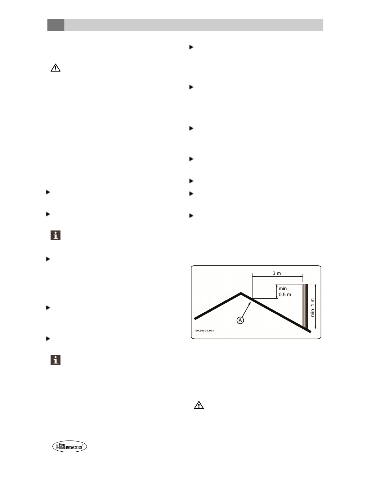
De schoorsteenmoet minimaal 4meter hoog zijn.
Als vuistregel geldt: 60cm boven de nok van het
dak.
Als de nok van het dak meer dan 3meter is verwijderdvan deschoorsteen: houd dematen aandie
in de volgende figuur zijn aangegeven. A = het
hoogste punt van het dak binnen een afstand van
3meter.
Ventilatie van de ruimte
Voor een goede verbrandingheeft het toestel lucht
(zuurstof) nodig. Die lucht wordt via regelbareluchtinlatenaangevoerd vanuit de ruimte waarhet toestel
is geplaatst.
Bij onvoldoende ventilatie vindt onvolledige verbranding plaats, waardoor zich giftige gassen
Page 11
Wijzigingen op grond van technische verbeteringen voorbehouden
11
in de ruimte kunnen verspreiden.
Een vuistregel is dat de luchttoevoer 5,5cm²/kW
moet zijn. Extra ventilatie is nodig:
Als het toestel in een ruimte staat die goed is geïsoleerd.
Als er mechanische ventilatie is, bv een centraal
afzuigsysteem of een afzuigkap in een open keuken.
U kunt voor extra ventilatie zorgen door een ventilatierooster in de buitenmuur te laten plaatsen.
Zorg dat andere luchtverbruikende apparaten (zoals
eenwasdroger, ander verwarmingstoestel of badkamerventilator) eeneigen buitenluchtaanvoer hebben, of zijn uitgeschakeld wanneer u het toestel
stookt.
Vloer en wanden
De vloer waarop het toestel wordt geplaatst, moet voldoendedraagvermogen hebben. Voor het gewicht van
het toestel: zie de bijlage "Technische gegevens".
In de vloeronderhet toestel en in de wanden
rond het toestel mogen zich geen elektrische
leidingenbevinden.
Onder het toestel moeten alle brandbare materialen verwijderd zijn of beschermd zijn met
minimaal 6 cm betonplaat.
Brandbare wandengrenzend aan het toestel
moeten beschermd worden met minimaal 10
cm stenen wand en 5 cm isolatie.
Bescherm niet-brandbare wanden grenzend
aanhet toestel met minimaal 2,5 cm isolatie ter
voorkoming van scheurvorming.
Bescherm een brandbare vloerdoor middel van
eenonbrandbare vloerplaat tegen warmte-uitstraling en eventueel uitvallende assen. Zie de
bijlage "Afstand tot brandbaar materiaal".
Zorg voor voldoende afstandtussen het toestel
en brandbare materialen zoals meubels.
Zorg voor voldoende ventilatie rondom brandbare materialenzoals een sierbalk. Zie bijlage
"Afstand tot brandbaar materiaal".
Een vloerkleed moet minimaal 80cm van het
vuur verwijderdzijn.
Plaats geenbrandbare materialen binnen
50cm van de eventueleconvectie-uitlaatopeningen.
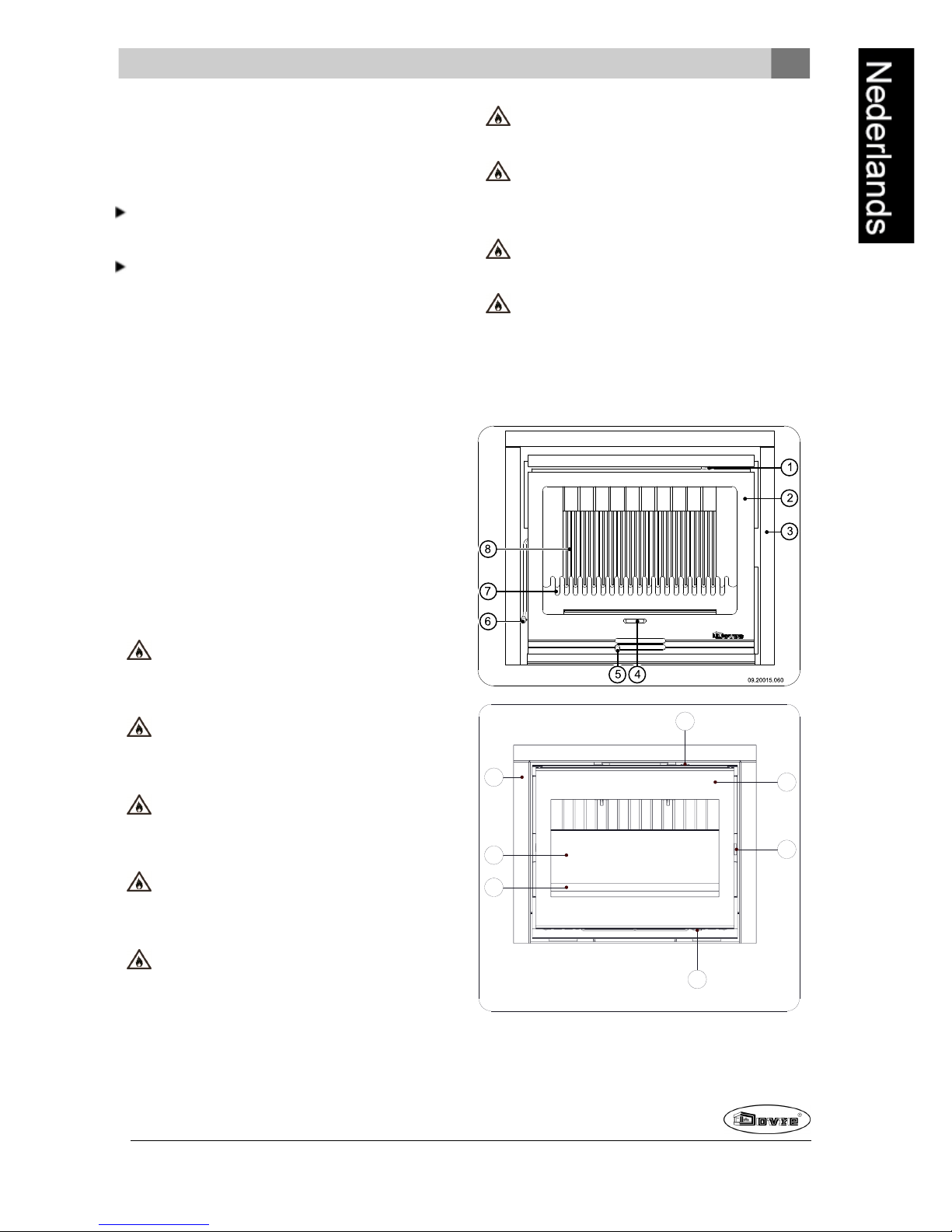
Productbeschrijving
8
7
1
2
5
6
3
09-20020-183
Page 12
12
Wijzigingen op grond van technische verbeteringen voorbehouden
1. Secundaireluchtschuif
2. Deur
3. Uitwendig sierkader
4. Schudstang
5. Primaire luchtschuif
6. Grendel
7. Vuurkorf
8. Vuurvaste binnenplaten
Kenmerken van het toestel
Het toestel wordt geleverd met eenlosse handgreep voor het openen van dedeur, de zogenaamde "koudehand".
Het toestel wordt geleverd met eentweede losse
handgreep voor het verwijderen van de aslade, de
zogenaamde "koude hand"; zie volgende figuur.
De draairichtingvan dedeur kan gewijzigd worden.
Het toestel wordt geleverd met eenrechtsdraaiende deur. Vooreen linksdraaiende deur is
eenoptioneel verkrijgbare grendelstang nodig. De
instructies voor het wijzigen van de draairichting
worden met deze grendelstang meegeleverd.
De draairichtingvan dedeur kan gewijzigd worden.
Het toestel wordt geleverd met eenlinksdraaiende
deur. Voor een rechtsdraaiendedeur is een optioneel verkrijgbare grendelstang nodig. De instructies voor het wijzigen van dedraairichting worden
met deze grendelstangmeegeleverd.
Het toestel wordt geleverd met eenaansluitset
voor de buitenluchttoevoer.
Het toestel is niet geschikt voor continu gebruik.
De inzethaard heeft een geïntegreerd convectiesysteem. Bij de inbouw van het toestel hoeft
er dus geenafzonderlijke convectieruimte
gebouwd te worden en de toepassing van luchtinlaatroosters en luchtuitlaatroosters ten behoeve
van de convectie is overbodig.
De ruimte tussen degietijzeren haard en de stalen convectiekast doet dienst als convectieruimte. Onderaanhet toestel wordt de
omgevingslucht aangezogen. De lucht wordt
om de haard geleid waarde lucht verwarmd
wordt. Vervolgens verlaat de verwarmde lucht
aande voorzijde de convectieruimte doorde
luchtopening aande bovenzijde van de haard.
Het toestel is uitgerust met twee extra aansluitingenom convectiewarmte te transporteren
naar andere ruimtes.
Het toestel is uitgerust met twee ingebouwde ventilatoren die deconvectie bevorderen. De draaisnelheid van deventilatoren is regelbaar door een
toerenregelaar. Deze toerenregelaar is meegeleverd. De ventilator en toerenregelaar worden
aangesloten op het elektriciteitsnet; zie de paragraaf "Ventilator aansluitenop het elektriciteitsnet".
De ventilator werkt thermostatisch, dat
houdt in dat de ventilator pas in werking
treedt als de inzethaard voldoende warm is
en dat de ventilator uitschakelt als de inzethaard voldoende is afgekoeld.
Het toestel kan geleverd worden met een uitwendig
kaderwaaru een sierkader op kunt bevestigen.Het
sierkader is optioneel leverbaar.
Page 13
Wijzigingen op grond van technische verbeteringen voorbehouden
13
Installatie
Voorbereiding
Controleer het toestel onmiddellijk bij ontvangst op
(transport)schadeen eventuele gebreken.
Als u (transport)schade of gebrekenhebt
geconstateerd, neem het toestel dan niet in
gebruik en stel de leverancier op de hoogte.
Verwijder de demontabele onderdelen (vuurvaste
binnenplaten, stookbodem, vuurkorf, asluik en
aslade) uit het toestel voordat u het toestel gaat
installeren.
Door de demontabele onderdelen te verwijderen, kunt u het toestel gemakkelijker verplaatsen en beschadiging voorkomen.
Let bij het verwijderenvan demontabele onderdelen op hun oorspronkelijke positie, om ze
later weer op dejuiste plaats te kunnen aanbrengen.
1. Open de deur van het toestel.
2. Verwijder de vuurvaste binnenplaten.
Gietijzeren binnenplatenbeschermen de verbrandingskameren gevenwarmte dooraan de
omgeving.
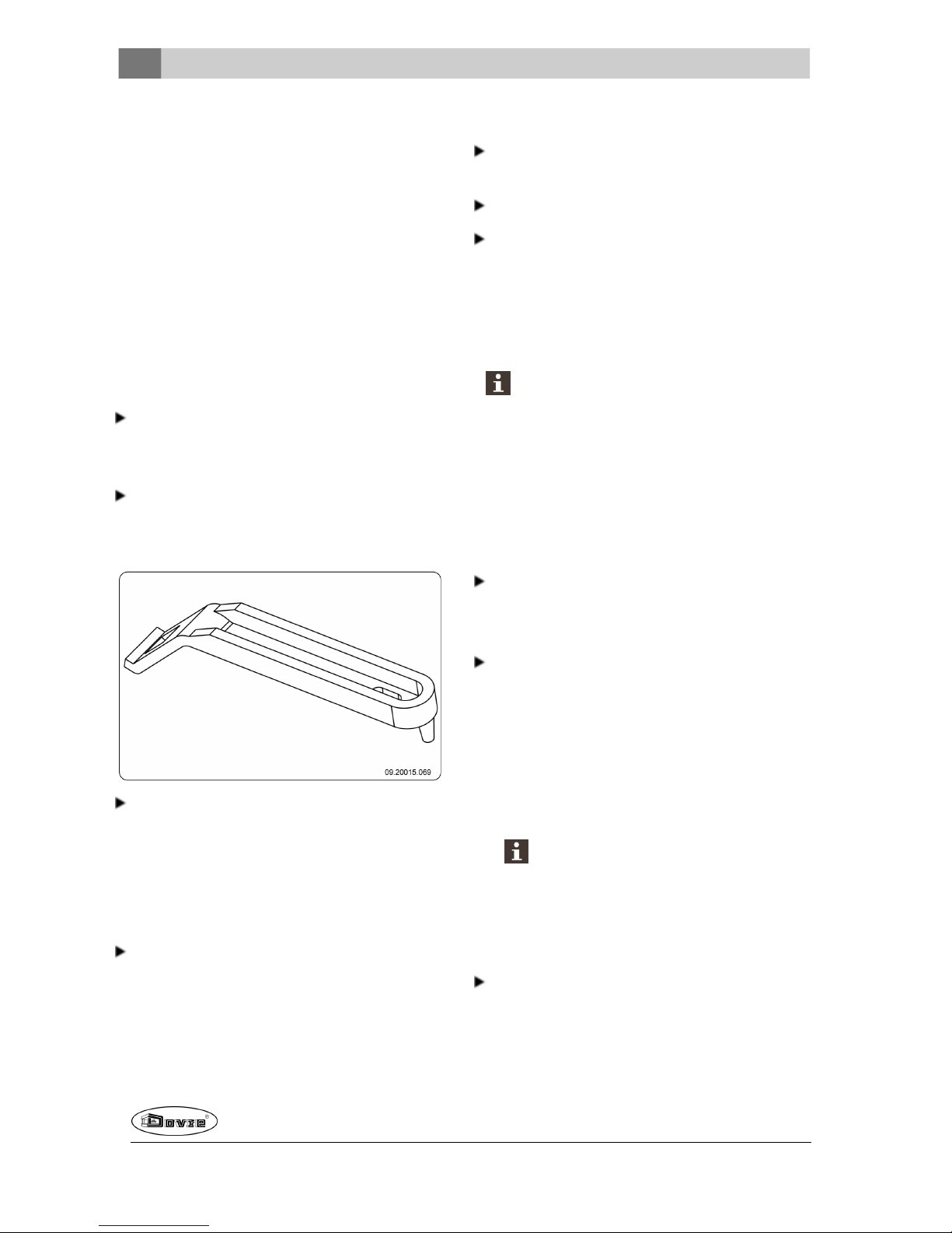
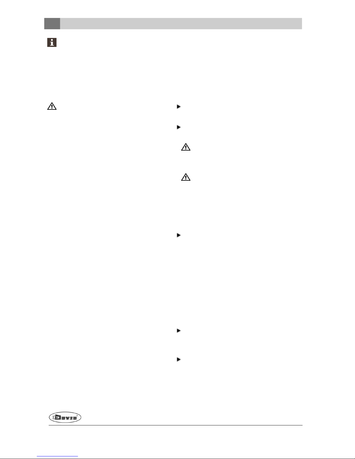
Handgreep monteren
Het toestel wordt geleverd met eenlosse handgreep,
de zogenaamde"koude hand".
De vorm van de koude hand is afhankelijk van de uitvoeringsvorm van het toestel.
Bevestig met bijgeleverde schroef M8x50het houten
handvat aanhet verloopstuk; zie volgende figuur.
09-20015.088
Voor het openen van de deur zie volgende figuur.
09-20020-182
Draairichting van de deur wijzigen
Desgewenst kan de draairichting van de deurgewijzigd worden. Het toestel wordt geleverd met een
rechtsdraaiendedeur. Volg onderstaande instructies.
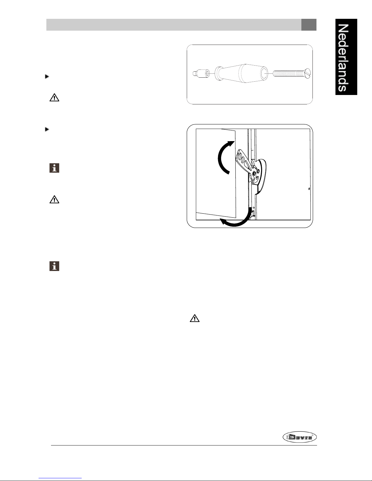
1. Schroef de grendel van de deur.
2. Schroef de sluitnok van de deur uit de stijl.
3. Trek de scharnierpennen uit de scharnieren.
Zorg ervoor dat u de deur voldoende ondersteunt; zonder scharnierpennen kan de deur
onverwachts los komen van het toestel.
4. Verwijder de deurvan het toestel.
5. Neem de sluitringen van de scharniernok en plaats
deze aan deandere zijde van het toestel.
6. Positioneer de deur boven descharniernokken en
plaats de scharnierpennen in de scharnieren.
Page 14
14
Wijzigingen op grond van technische verbeteringen voorbehouden
7. Schroef de grendel aan de andere zijde van de
deur.
8. Schroef de sluitnok aan de andere zijde van de
deur.
Opmerking: Voor het bijstellen van de deursluiting zie
het hoofdstuk "Onderhoud".
Ventilator aansluiten op het
elektriciteitsnet
De inzethaard wordt geleverd met twee ingebouwde
ventilatoren enmet een losse toerenregelaar. Daarnaast is het toestel uitgerust met een thermo-switch
die deventilator in- enuitschakelt bij eenvast ingestelde temperatuur.
Deze onderdelenmoeten ophet elektriciteitsnet aangesloten worden volgens een van de onderstaande
aansluitschema's.
Het aansluitschema is modelspecifiek.
Laat de aansluiting uitvoeren door een deskundiginstallateur.
De inzethaard is voorzienvan een drie-aderig
snoer.
De inzethaard moet van het elektriciteitsnet
gescheiden zijn door middel van eendubbelpoligeschakelaar.
Zorg voor een goedeaarding van deinzethaard.
Zie bijlage 2 vooruitgebreide aansluitschema's.
Inbouwen in een bestaande
schouw
Voor het inbouwen van de haard in een bestaande
schouw volgt u onderstaande instructies:
1. Zet het toestel op de juiste hoogte, vlak en waterpas.
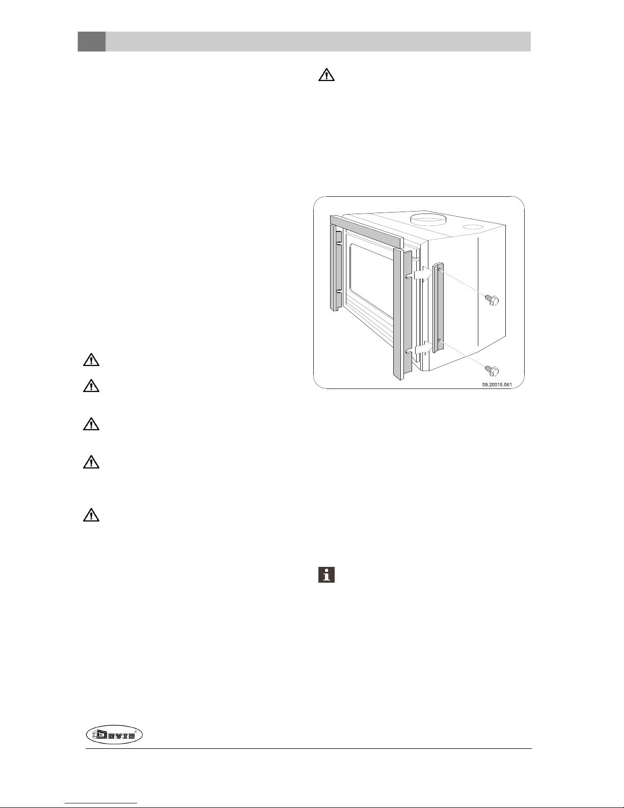
Houd deelektrische kabel van het toestel vrij.
2. Als u een uitwendig kader op het toestel gaat plaatsen moet u de meegeleverde klemplaten aan de zijkanten van het toestel bevestigen zonder de
schroeven helemaal vast te draaien. Het uitwendigkader klemt namelijk tussen het toestel en
de klemplaten; zie volgende figuur.
3. Sluit de basis van de schoorsteen af met een
onbrandbaarmateriaal.
4. Maak een opening in de basis ten behoeve van de
afvoerbuis met diameter 150 mm.
5. Centreer deopening in debasis met de aansluitkraag op de haard.
6. Plaats de afvoerbuis in de opening. Zorg ervoor
dat de buis naar benedengetrokken kan worden
zodat hij op de aansluitkraag past. Gebruik bijvoorbeeld eenbuis met regelbare lengte.
Bij gebruik van RVS-flexibele buis: schroef de
buis aanhet meegeleverde aansluitstuk, plaats
het aansluitstuk in de aansluitkraag enfixeer
het aansluitstuk door detwee lipjes naar buiten
te buigen.
De volgende figuur geeft een voorbeeld van deplaatsing van een inbouwhaard in een schouw die volgens
Page 15
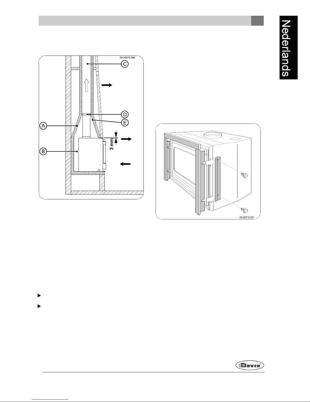
Wijzigingen op grond van technische verbeteringen voorbehouden
15
bovenstaande instructies en voorschriften is
gebouwd.
A Bestaande haard
B Ventilatieruimte (minimaal 15mm)
C Bestaandrookkanaal
D Vuurvast materiaal of een verbindingstuk
E Opening ter voorkomingvan drukopbouw
Inbouwen in een nieuwe
schouw
De installatie van de inbouwhaard bestaat uit twee
onderdelen:
De plaatsing en aansluitingvan de inbouwhaard
De schouw rondde inbouwhaard opbouwen.
Inbouwhaard plaatsen en
aansluiten
1. Zet het toestel op de juiste hoogte, vlak en waterpas.
2. Als u een uitwendig kader op het toestel gaat plaatsen moet u de meegeleverde klemplaten aan de zijkanten van het toestel bevestigen zonder de
schroeven helemaal vast te draaien. Het uitwendigkader klemt namelijk tussen het toestel en
de klemplaten; zie volgende figuur.
3. Zorg dat tussen de bestaande wanden, voorzien
van de benodigdeisolatie (zie het hoofdstuk
"Installatiecondities"), en de achterkant van het
toestel minimaal 15 mm vrije convectieruimte is.
4. De inbouwhaard mag niet het metselwerk dragen.
Gebruik desgewenst een ondersteuning zoals een
draagijzer. Laat tussen de ondersteuning en het
toestel minimaal 3 mm speling.
4. Sluit het toestel hermetisch aan opde schoorsteen.
5. Controleer de trek in de schoorsteen en de afdichting van de aansluiting op het rookgasafvoerkanaal door een klein hevig proefvuur te
maken van krantenpapier en droog dunhout.
Page 16

16
Wijzigingen op grond van technische verbeteringen voorbehouden
Wacht bij nieuw metselwerk tot het metselwerk voldoendedroogis.
Convectielucht aftappen
Het toestel is uitgerust met twee extra aansluitingen
om convectiewarmte te transporteren naar andere
ruimtes. In deze ruimtes dienen luchtuitlaatroosters
aanwezig te zijn. Als u van deze functie gebruik wilt
maken gaat u als volgt te werk:
1. Verwijder de twee drukplaten bovenop de convectiekast door deze met een hamer los te tikken.
2. Monteer detwee meegeleverde aansluitkragen
met diameter 125 mm op deontstane openingen
met de meegeleverde M8x16 schroeven en M8
bouten.
3. Sluit hierop flexibele buis met diameter 125 mm
aanen voer deze naar de gewenste ruimtes.
4. Sluit de flexibele slang aan op deuitlaatroosters in
de ruimtes.
Opbouw van de nieuwe schouw
In de schouw maakt u de convectieruimte. In deze
ruimte moet lucht vrij kunnen bewegen. Er moet lucht
aangezogen kunnen worden voor de verbranding en
de door de inbouwhaard verwarmde lucht (deconvectielucht) moet vrij de te verwarmen ruimte in kunnenstromen; zie volgende figuur.
Volg bij de bouw van de schouw de volgende
voorschriften:
De bovenzijde van de schouw moet luchtdicht afgesloten zijn met een afsluitplaat van onbrandbaar en
hittebestendig materiaal.
De afsluitplaat moet waterpas liggen en minimaal
30 cm onder de rookgasopening in het plafond
geplaatst zijn.
Desgewenst kunt u aan de bovenzijdevan de
schouw en vlak onder deafsluitplaat een extra
luchtuitlaatrooster plaatsen.
Gebruik in de inbouwruimte geen brandbaar
materiaal envoorkom de werkingvan warmtebruggen bij het gebruik van warmtegeleidende materialen.
Volg onderstaande instructie bij de opbouw van
de schouw:
1. Metsel de voet van dehaard.
Zorg dat de deurvan dehaard vrij over het plateau van de haard kan draaien.
2. Metsel de haard verder optot aan de rookvang.
Zorg dat er altijd 2 mm speling blijft tussen de
inbouwhaard en metselwerk om de warmteuitzetting van de inbouwhaardop te vangen.
3. Bekleeddesgewenst de binnenzijde van de
schouw met reflecterend isolatiemateriaal.
Extra bekleding van deinbouwruimte voorkomt
onnodige warmteuitstraling naar mogelijke buitenmurenen/of naast gelegen ruimtes. Het
voorkomt ook aantasting van de spouwmuurisolatie.
4. Metsel de schouw verder af tot aan de rookgasopening in het plafond.
De inbouwhaard mag niet het metselwerk dragen. Gebruik een ondersteuning zoals een
draagijzer. Laat tussen de ondersteuning en
het toestel minimaal 3 mm speling.
5. Sluit de inbouwruimte af met de afsluitplaat.
6. Plaats onder deafsluitplaat een luchtrooster in verband met de ventilatie van het toestel.
7. Maak boven de afsluitplaat een opening om eventuele drukopbouw te voorkomen.
De volgende figuur geeft een voorbeeld van deplaatsing van een inbouwhaard in een schouw die volgens
bovenstaande instructies en voorschriften is
gebouwd.
Page 17
Wijzigingen op grond van technische verbeteringen voorbehouden
17
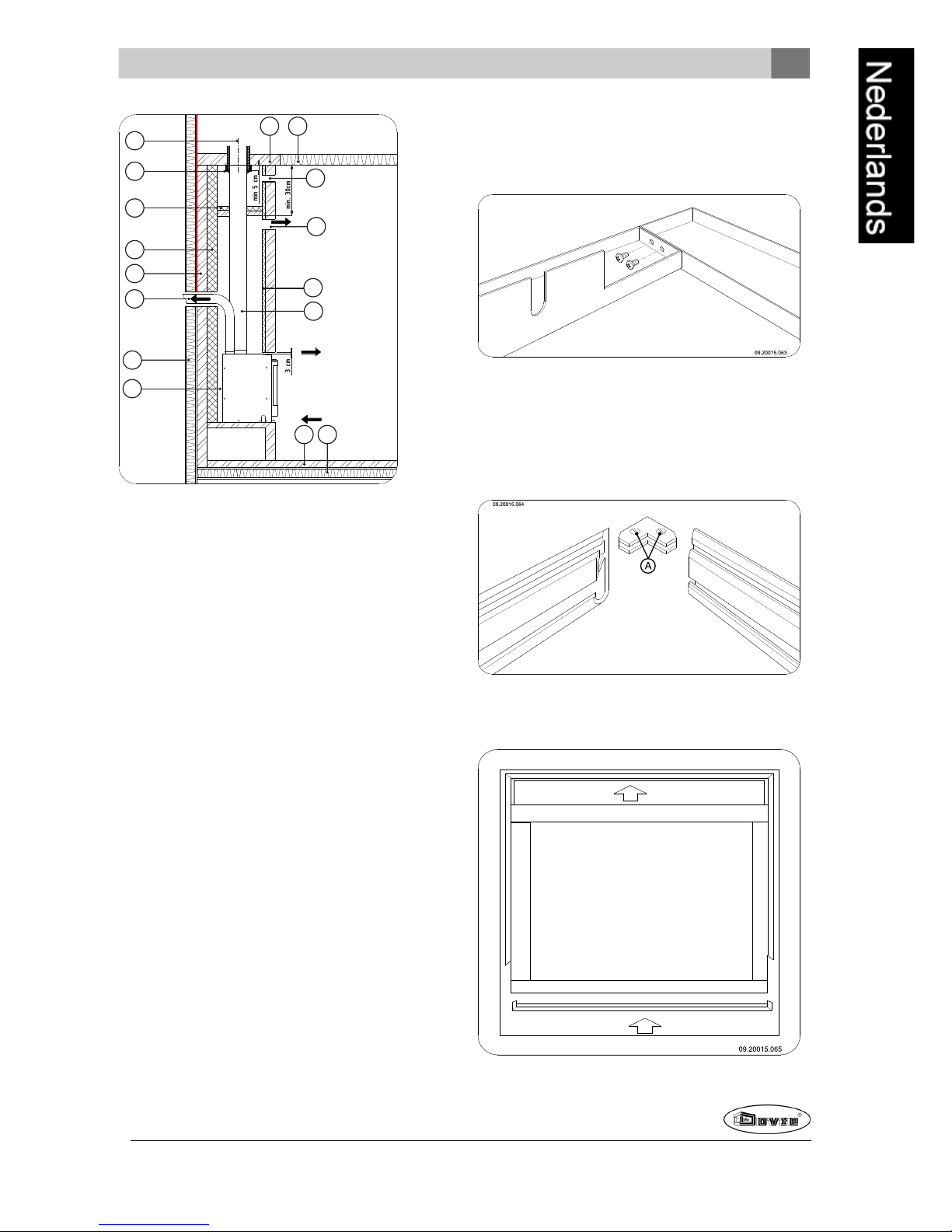
A
B
C
D
E
F
G
H I
J
K
L M
09.20015.057
P
N
O
A Schoorsteen
B Vuurvast materiaal of een verbindingstuk
C Afdekplaat
D Isolatiemateriaal (minimaal 5 cm)
E Onbrandbare muur
F Brandbare muur
G Ventilatieruimte (minimaal 15 mm)
H Onbrandbaar plafond
I Brandbaar plafond
J Convectieluchtopening
K Isolatie (optioneel)
L Onbrandbare bodem
M Brandbare bodem
N Openingtegen drukopbouw
O Aansluitbuis
P Convectielucht andere ruimte
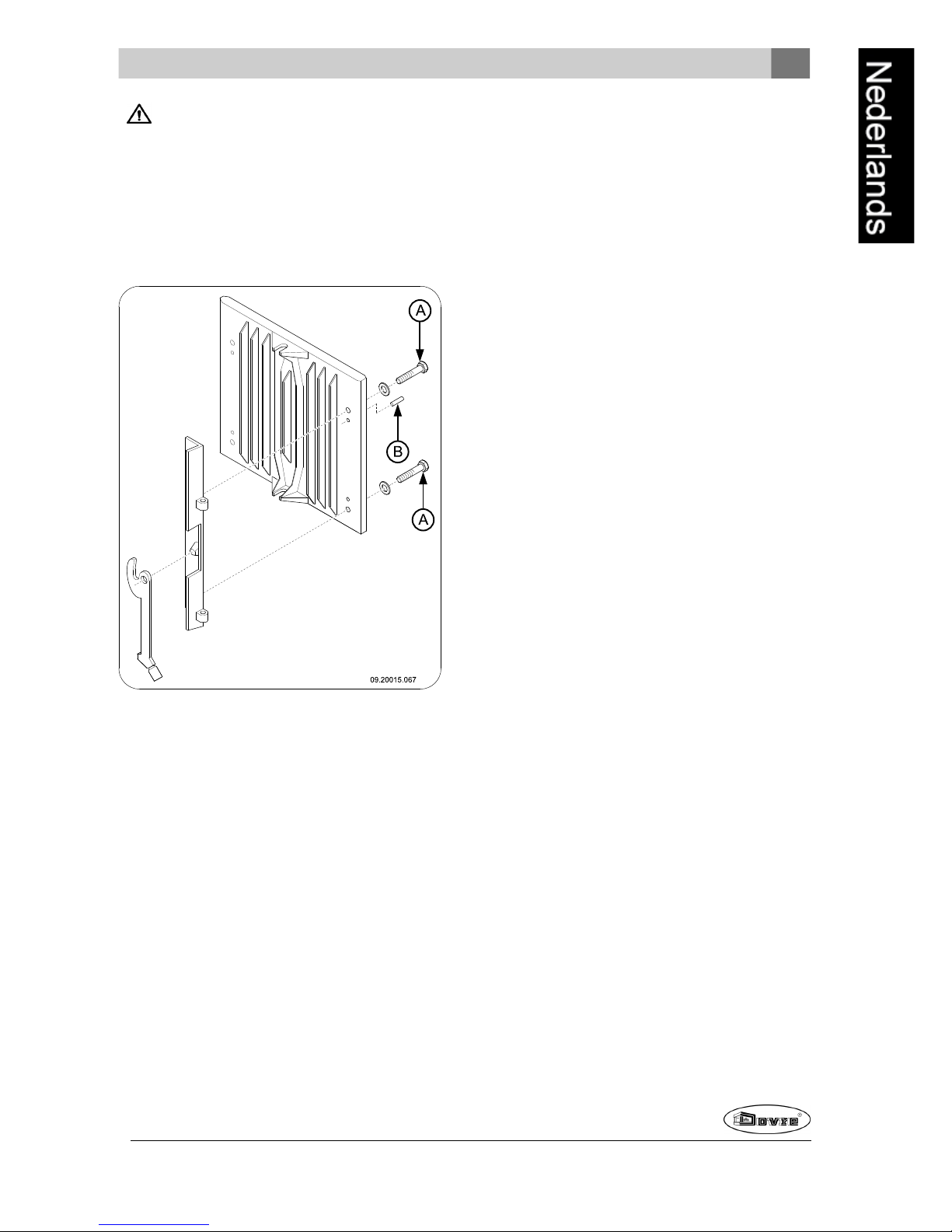
Uitwendige kader monteren
Het toestel kan geleverd worden met een bijbehorend
driezijdig of vierzijdig uitwendig kader. Optioneel is
ook een sierkader leverbaar dat aan het uitwendig
kaderwordt bevestigd.
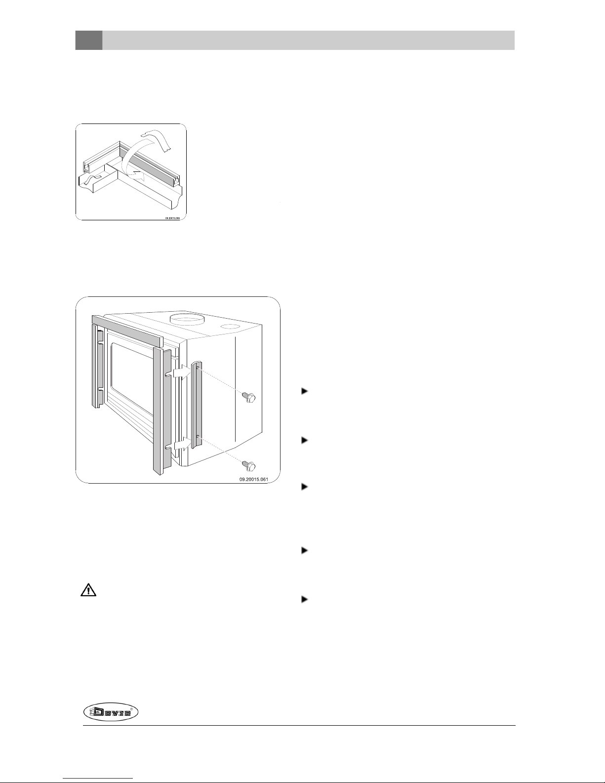
1. Monteer het uitwendig kader door de zijdes met
twee schroevenaan elkaar te verbinden; zie volgende figuur.
2. Monteer het sierkaderdoor de zijdes van het sierkadermet behulpvan het verbindingselement te
koppelen en vervolgens te fixeren door de twee
schroeven (A) van het verbindingselement aan te
draaien; zie volgendefiguur.
3. Centreer het sierkaderten opzichte van het uitwendigkader; zie volgende figuur.
Page 18
18
Wijzigingen op grond van technische verbeteringen voorbehouden
4. Plaats aan elke zijde drie ondersteuningsplaatjes
tussen het sierkader enhet uitwendig kader; zie
volgende figuur.
5. Bevestig het (samengestelde) kader op het toestel
door de bevestigingslippen aan de verticale zijdes
van het kader, tussen het toestel en deklemplaten
te schuiven; zie volgende figuur.
Afwerking
1. Plaats alle gedemonteerdeonderdelen op de juiste
plaats terug in het toestel.
2. Zorg dat de nieuw gebouwde schouw voldoende
droog is, voordat u gaat stoken.
Laat het toestel nooit branden zonder de vuurvaste binnenplaten.
Het toestel is nu klaar voor gebruik.
Gebruik
Eerste gebruik
Wanneer u het toestel voorhet eerst gebruikt, stook
het dan enkeleuren flink door. Hierdoor zal de hittebestendigelak uitharden. Hierbij kan wel wat rook
en geurhinder ontstaan. Zet eventueel in de ruimte
waar het toestel staat de ramenen deureneven open.
Brandstof
Het toestel is geschikt voorhet stoken van natuurlijk
hout (gezaagd en gekloofd en voldoende droog), voor
het stoken van bruinkoolbriketten en voorhet stoken
van antracietkolen.
Gebruik geen andere brandstoffen, want die kunnen
leiden tot ernstige schade aan het toestel.
De volgende brandstoffen mag u niet gebruiken omdat
zij het milieu vervuilen, en omdat zij het toestel en de
schoorsteen sterk vervuilen waardoor schoorsteenbrand kan ontstaan:
Behandeld hout, zoals sloophout, geverfd hout,
geïmpregneerd hout, verduurzaamdhout, multiplex
en spaanplaat.
Kunststof, oud papieren huishoudelijk afval.
Hout
Gebruik bij voorkeur hardloofhout zoals eik, beuk,
berk en fruitbomenhout. Dit hout brandt langzaam
met rustige vlammen. Naaldhout bevat meer hars,
brandt sneller en geeft meer vonken.
Gebruik gedroogdhout met een vochtpercentage
van maximaal 20%. Hiervoor moet het hout minstens 2 jaar zijn gedroogd.
Zaaghet hout op maat en klief het als het nog vers
is. Vers hout klieft gemakkelijker en gekloven hout
droogt beter. Bewaar het hout onder een afdek
waar de wind vrij spel heeft.
Page 19
Wijzigingen op grond van technische verbeteringen voorbehouden
19
Gebruik geen nat hout. Nat hout geeft geen warmte
omdat alle energie gaat zitten in het verdampen
van vocht. Dit geeft veel rook en roetaanslagop de
deur van het toestel en in de schoorsteen. De
waterdamp condenseert in het toestel en kan langs
naden uit het toestel lekken en zwarte vlekken op
de vloergeven. De waterdamp kan ook in de
schoorsteen condenseren en creosoot vormen.
Creosoot is zeer brandbaar en kan schoorsteenbrand veroorzaken.
Bruinkoolbriketten
Bruinkoolbriketten hebben ongeveer dezelfdebrandeigenschappen als hout.
Zorg voor een goed houtskoolbed voordat u bruinkoolbriketten gaat stoken.
Volg voorhet aanmaken van dehaard de instructies in de paragraaf "Aanmaken".
Antracietkolen
Antracietkolen worden ingedeeld in categorieën op
grond van kenmerken, soms bij wet bepaald, zoals
het percentage vluchtige stoffen. Het asgehalte van
antracietkolen ligt tussen de 3% en 13%. Hoe lager
het asgehalte hoe hogerde stookwaarde en hoe mindervaak u hoeft te ontassen.
Gebruik bij voorkeur categorieA antracietkolen met
eenlaag asgehalte.
Gebruik het aanbevolen formaat 12/22of 20/30.
Volg voorhet aanmaken van dehaard de instructies in de paragraaf "Aanmaken".
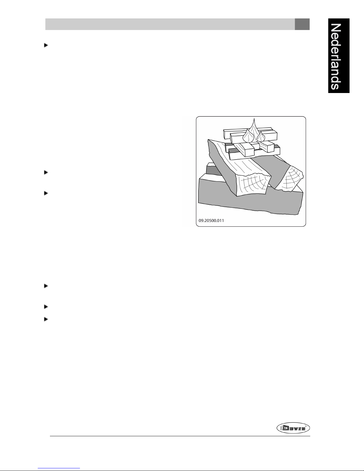
Aanmaken
U kunt controleren of de schoorsteen voldoende trek
heeft door boven devlamplaat een prop krantenpapier
aante steken. Bij een koude schoorsteen is er vaak
onvoldoende trek in de schoorsteen en kan er rook in
de kamer komen. Doorhet toestel op de hier beschreven manier aan te maken, voorkomt u dit probleem.
1. Stapel twee lagen middelgrote houtblokken kruislings op elkaar.
2. Stapel bovenop de houtblokken twee lagenaanmaakhoutjes kruislings op elkaar.
3. Legeen aanmaakblokje tussen de onderste laag
aanmaakhoutjes en steek het aanmaakblokje aan
volgens de instructies op de verpakking.
4. Sluit de deur van het toestel en zet de primaire
luchtinlaat en de secundaire luchtinlaat van het toestel open; zie volgende figuur.
5. Laat het aanmaakvuurflink doorbranden totdat het
eengloeiend houtskoolbed is geworden. Hierna
kunt u eenvolgendevulling doen enhet toestel
gaan regelen; zie de paragraaf "Stoken met hout".
Bediening van de luchtschuiven
Het toestel heeft twee luchtschuiven. De primaire
luchtschuif zit onderaan in dedeur en regelt de lucht
onder het rooster. Boven de deur bevindt zich de
secundaire luchtschuif die de lucht regelt voor het glas
(air-wash systeem).
De luchtschuif kan worden bediend met de koude
hand. De vorm van de koude hand is afhankelijk van
de uitvoeringsvorm van het toestel.
Voor de open- en dichtpositie van de luchtschuif, zie
de volgende afbeeldingen.
Page 20
20
Wijzigingen op grond van technische verbeteringen voorbehouden
09-20020-181
09-20020-180
l = Dicht
o
= Open
Stoken met hout
Nadat u de instructies voor het aanmaken hebt
gevolgd:
1. Open langzaam de deur van het toestel.
2. Verdeel het houtskoolbed gelijkmatig over de
stookvloer.
3. Stapel enkele houtblokken op het houtskoolbed.
Losse stapeling
Bij een losse stapeling verbrandt het hout vlug omdat
de zuurstof elk stuk hout gemakkelijk kan bereiken.
Gebruik een losse stapeling als u kort wilt stoken.
Compacte stapeling
Bij een compacte stapeling verbrandt het hout langzamer omdat de zuurstof maar enkele stukken hout
kan bereiken. Gebruik een compacte stapelingals u
langer wilt stoken.
4. Sluit de deur van het toestel.
5. Sluit de primaireluchtinlaat en laat de secundaire
luchtinlaat openstaan.
Vul het toestel voor maximaal een derde.
Page 21
Wijzigingen op grond van technische verbeteringen voorbehouden
21
Stoken met bruinkoolbriketten
Bruinkoolbriketten branden opnagenoeg dezelfde
manier als hout. Zorg met behulp van de primaireluchtinlaat voor voldoende luchttoevoer onder het vuur. Zie
verder de paragraaf "Stoken met hout".
Het brandenvan bruinkoolbriketten geeft veel as. Verwijder deovertollig as regelmatig. Zie de paragraaf
"Ontassen" voor instructies.
Voor de eigenschappen enhet gebruik van de
bruinkoolbriketten: raadpleeguw leverancier
van de bruinkoolbriketten of zie de verpakking
van de bruinkoolbriketten.
Nadat u de instructies voor het aanmaken hebt
gevolgd:
1. Open langzaam de deur van het toestel.
2. Verdeel het houtskoolbed gelijkmatig over de
stookvloer.
3. Legde bruinkoolbriketten ophet houtskoolbed.
4. Sluit de deur.
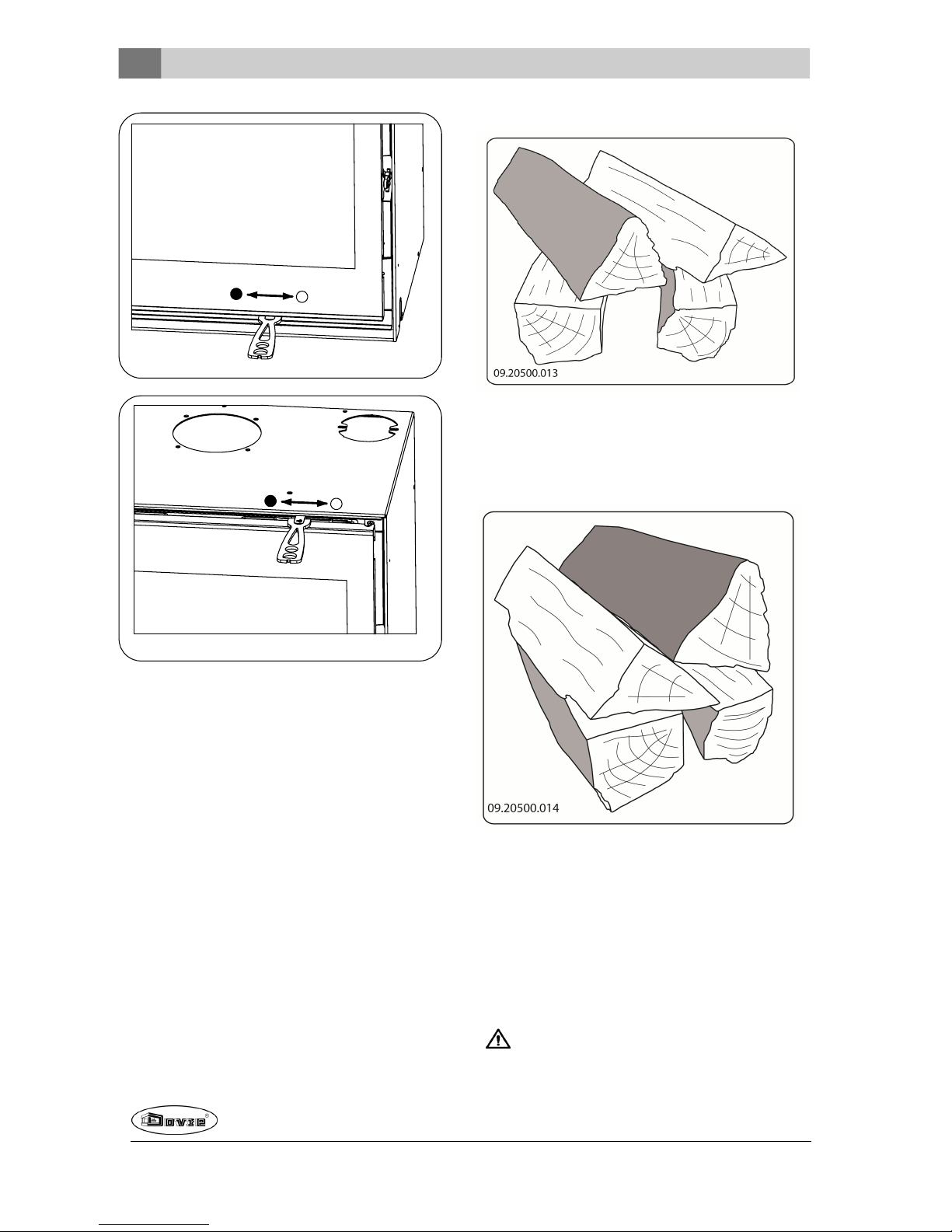
Stoken met antracietkolen
Gebruik een kolenkorf om de antracietkolen in te bewaren; zie volgendefiguur. De kolenmof is optioneel verkrijgbaar.
Sluit bij het stoken van antracietkolen altijd de
secundaire luchtschuif.
Zet het stookrooster open door deschudstang
naar voren te trekken.
Nadat u de instructies voor het aanmaken hebt
gevolgd:
1. Zet de primaire luchtschuif volledig open.
2. Open langzaam de deur van het toestel.
3. Verdeel het houtskoolbed gelijkmatig over de
stookvloer.
4. Verspreid een schep kolen op het houtskoolbeden
wacht met de volgende schep tot de kolen gaan
gloeien.
5. Voegnu meer kolen toe.
Let op dat u het vuur niet dooft doorin een keer
te veel kolen toe te voegen.
U heeft de maximale bijvulling bereikt als de
gloed van de vorige vulling nog net zichtbaar is.
6. Sluit de deur.
7. Laat de kolen 20 tot 30 minutenminuten goed doorbranden en regel deluchttoevoer met de primaire
luchtschuif.
8. Gebruik de schudstang om het rooster te schuddentot er gloeiende deeltje in deasla vallen.
9. Zet de primaire luchtschuif helemaal open.
10. Vul opnieuw kolen bij tot de maximale vulling.
Let op dat het rooster open staat door de
schudstangnaar voren te trekken.
11. Zet na enkel minuten de primaireluchtschuif in de
gewenste positie.
Als de vuurkorf of het schudrooster rood beginnente gloeien, bent u te hardaan het stoken.
Het schudrooster en/of de vuurkorf kunnen
daardoor vervormen.
Page 22
22
Wijzigingen op grond van technische verbeteringen voorbehouden
Regeling van de
verbrandingslucht
Het toestel heeft diverse voorzieningen voor de luchtregeling.
De primaire luchtschuif regelt de lucht onderhet rooster.
De secundaire luchtschuif regelt de lucht voorhet glas
(air-wash).
Adviezen
Stook nooit met open deur.
Stook het toestel regelmatig flink door.
Als u langdurig op lagestand stookt, kan zich
in de schoorsteen een afzetting vormen van
teer en creosoot. Teer encreosoot zijn zeer
brandbaar. Als de afzetting van deze stoffen te
groot wordt, kan bij eenplotselinge hoge temperatuur eenschoorsteenbrand ontstaan. Door
regelmatig flink doorstoken, verdwijnen eventuele afzettingen van teeren creosoot.
Daarnaast kan zich bij te laag stoken teer afzetten op de ruit en deur van het toestel.
Bij een mildebuitentemperatuuris het dus
beterom het toestel een paaruur intens te
laten branden, dan lange tijd laag te stoken.
Regel deluchttoevoer met de secundaire luchtinlaat.
De secundaire luchtinlaat belucht niet alleen
het vuur maar ook het glas, zodat het glas niet
snel vervuilt.
Zet de primaire luchtinlaat tijdelijk open als de luchttoevoer via de secundaireluchtinlaat onvoldoende
is of als u het vuur wilt aanwakkeren.
Regelmatig eenkleine hoeveelheid houtblokken bijvullen is beterdan veel houtblokken tegelijk.
Regelmatig eenkleine hoeveelheid bruinkoolbriketten of antracietkolen toevoegen is beter
danveel bruinkoolbriketten of antracietkolen tegelijk.
Doven van het vuur
Vul geen brandstof bij en laat de kachel gewoon uitgaan. Als een vuur wordt getemperddoor de luchttoevoer te verminderen, komen schadelijke stoffen
vrij. Laat daarom het vuur vanzelf uitbranden. Houd
toezicht op het vuurtotdat het goed is gedoofd. Als
het vuur volledig is gedoofd kunnen alle luchtschuiven
worden gesloten.
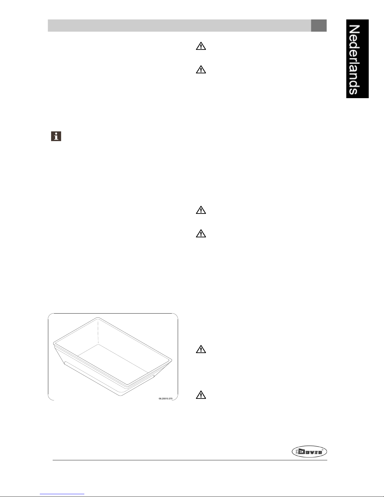
Ontassen
Na het stoken van hout blijft een relatief kleine hoeveelheid as over. Dit asbed is een goedeisolator voor
de stookbodem en geeft een betere verbranding. Laat
daarom gerust een dunlaagje as op de stookbodem liggen.
Na het stoken van bruinkoolbriketten en antracietkolen blijft er relatief veel as over. Verwijder regelmatig de overtollige as.
De as mag nooit de onderkant van het rooster
raken. Het rooster raakt dan oververhit en
beschadigd.
De luchttoevoerdoor de stookbodem mag echterniet
worden belemmerd ener mag zich geen as ophopen
achter een binnenplaat. Verwijder daarom regelmatig
de overtollige as.
1. Open de deur van het toestel.
2. Gebruik de schudstang om de overtollige as via
het rooster in de asla te laten vallen.
3. Verwijder de aslade met behulpvan debijgeleverde koudehand en leegde aslade; zie de
volgende twee figuren.
Page 23
Wijzigingen op grond van technische verbeteringen voorbehouden
23
4. Plaats de aslade terug en sluit de deur van het toestel.
Nevel en mist
Nevel en mist belemmerende afvoer van rookgassen
door de schoorsteen. Rook kan neerslaanen stankoverlast geven. Als het niet echt nodig is, kunt u bij
nevel enmist beter niet stoken.
Eventuele problemen
Raadpleegde bijlage "Diagnoseschema" om eventuele problemenbij het gebruik van het toestel op te
lossen.
Onderhoud
Volg deonderhoudsinstructies in dit hoofdstuk om het
toestel in goede staat te houden.
Schoorsteen
In veel landen bent u wettelijk verplicht de schoorsteen te laten controleren en onderhouden.
Aan het begin van het stookseizoen: laat de schoorsteen vegen door een erkend schoorsteenveger.
Tijdens het stookseizoen en nadat de schoorsteen
lange tijd niet is gebruikt: laat de schoorsteen controleren op roet.
Na afloop van het stookseizoen: sluit de schoorsteen af met eenprop krantenpapier.
Schoonmaken en ander
regelmatig onderhoud
Maak het toestel niet schoonwanneer het nog
warm is.
Maak de buitenkant van het toestel schoon met
eendrogeniet pluizende doek.
Na afloop van het stookseizoenkunt u de binnenkant
van het toestel goed schoonmaken:
Verwijder eventueel eerst de vuurvaste binnenplaten. Zie het hoofdstuk "Installatie" voor
instructies voor het verwijderen en aanbrengenvan
binnenplaten.
Maak eventueel de luchtaanvoerkanalen schoon.
Verwijder de vlamplaat boven in het toestel en
maak deze schoon.
Vuurvaste binnenplaten controleren
De vuurvaste binnenplatenzijn verbruiksonderdelen
die aan slijtage onderhevig zijn. Vermiculite binnenplaten zijn kwetsbaar. Stoot niet met houtblokken
tegende binnenplaten. Controleerde binnenplaten
regelmatig en vervang ze indien nodig.
Zie het hoofdstuk "Installatie" voor instructies voor
het verwijderenen aanbrengen van binnenplaten.
De isolerende vermiculite of chamotte binnenplaten kunnen haarscheuren gaan vertonen, maar dat heeft geen nadelig effect op
hunwerking.
Page 24
24
Wijzigingen op grond van technische verbeteringen voorbehouden
Gietijzeren binnenplatengaan lang meeals u
regelmatig as verwijdert die zich mogelijk
erachter ophoopt. Als opgehoopte as achter
eengietijzeren plaat niet wordt verwijderd, kan
de plaat de warmte niet meerafgeven aan de
omgeving enkan deplaat vervormen of scheuren.
Laat het toestel nooit branden zonder de vuurvaste binnenplaten.
Klep en vlamplaat demonteren
Zowel de klep als de vlamplaat zijn demontabel. Om
de vlamplaat te demonteren moet eerst de klep ende
klepstang worden verwijderd.
1. Open de deur van het toestel.
2. Til de gesloten klep iets op en schuif hem boven
de vlamplaat zodat beide vrij zijn.
3. Verwijder de klep en de klepstanguit het toestel.
4. Schroef het steunplaatje los door de de moerM8
los te draaien. Het steunplaatje bevindt zich in het
midden tegen de topplaat van het toestel.
5. Til de vlamplaat aan de voorkant op, trek de vlamplaat naar voren en neem de vlamplaat uit het toestel.
Opmerking: Volg voor demontagevan deklep ende
vlamplaat, voorhet in gebruik nemen van het toestel,
bovenstaande instructies in omgekeerde volgorde.
Glas schoonmaken
Goed schoongemaakt glas neemt minder snel vuil op.
Ga als volgt te werk:
1. Verwijder stof en loszittend roet met een droge
doek.
2. Maak het glas schoon met kachelruitenreiniger:
a. Breng kachelruitenreiniger aan op een keu-
kenspons, wrijf het gehele glasoppervlak in en
laat even inwerken.
b. Verwijder het vuil met een vochtige doek of
keukenpapier.
3. Maak het glas nogmaals schoon met een gewoon
glasreinigingsproduct.
4. Wrijf het glas schoon met een droge doek of keukenpapier.
Gebruik geen schurende of bijtende producten om
het glas schoonte maken.
Gebruik schoonmaakhandschoenen om uw handente beschermen.
Als het glas van het toestel is gebroken of
gebarsten, moet dit glas wordenvervangen
voordat u het toestel opnieuw in gebruik neemt.
Voorkom dat kachelruitreinigertussen het glas
en degietijzeren deur loopt.
Smeren
Hoewel gietijzer enigszins zelfsmerend is, moet u
bewegende delen toch regelmatig smeren.
Smeerde bewegende delen (zoals geleidersystemen, scharnierpennen, grendels en luchtschuiven) met hittevast vet dat verkrijgbaar is bij
de vakhandel.
Afwerklaag bijwerken
Kleine lakbeschadigingenkunt u bijwerken met een
spuitbus speciaal hittebestendige lak die verkrijgbaar
is bij uw leverancier.
Afdichting controleren
Controleer of het afdichtingskoord van de deur nog
goed afsluit. Afdichtkoord verslijt en moet tijdig wordenvervangen.
Controleer het toestel op luchtlekken. Kit eventuele
kierendicht met kachelkit.
Page 25
Wijzigingen op grond van technische verbeteringen voorbehouden
25
Laat de kit goed uitharden voordat u het toestel
aanmaakt, anders blaast het vocht in de kit op
en ontstaat opnieuw een lek.
Deur bijstellen
Controleer of de deur goedsluit en stel zonodigde
scharnierstijl bij; zie volgende figuur.
1. Open de deur van het toestel; de scharnierstijl is
nu zichtbaar en toegankelijk.
2. Draai de twee bevestigingsbouten van de scharnierstijl iets los. De bevestigingsboutenbevinden
zich aan de binnenzijde van de haard.
3. Verschuif de scharnierstijl in de gewenste positie.
4. Gebruik de stelschroeven om de scharnierstijl in
de breedte van het toestel te positioneren.
5. Draai de twee bevestigingsbouten vast en controleer de sluiting van de deur.
Page 26
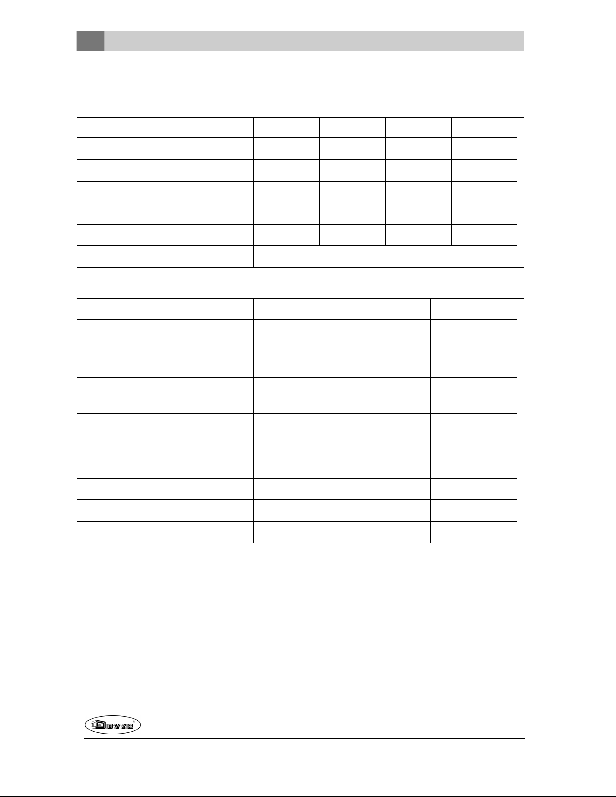
Bijlage 1: Technische gegevens
Model 2200 / 2210 / 2220 / 2020
Model 2200 2210 2220 2020
Nominaal vermogen 8 kW 8 kW 8 kW 7 kW
Schoorsteenaansluiting(diameter) 150mm 150mm 150mm 150mm
Gewicht 140kg 175 kg 150kg 130 kg
Aanbevolenbrandstof Hout Hout Hout Hout
Kenmerk brandstof, max. lengte hout 50 cm 50 cm 50 cm 40 cm
Elektrische aansluiting 230V, 50 Hz, 0,5 A
Brandstof Hout Bruinkoolbriketten Antracietkolen
Massadebiet van rookgassen 7,7 g/s 8,9 g/s 7,8 g/s
Temperatuurstijging gemeten in demeetsectie
295K 289 K 272K
Temperatuur gemeten aan deuitgang van
het toestel
340°C - -
Minimum trek 14 Pa 14 Pa 14 Pa
CO-emissie (13%O2) 0,10 % 0,06% 0,04 %
NOx-emissie (13% O2) 106mg/Nm³ - -
CnHm-emissie (13%O2) 51 mg/Nm³ - -
Stofemissie 31 mg/Nm³ - -
Rendement 78,3 % 75,4 % 76,4 %
26
Wijzigingen op grond van technische verbeteringen voorbehouden
Page 27
Wijzigingen op grond van technische verbeteringen voorbehouden
27
Model 2500 / 2510 / 2520 / 2620
Model 2500 2510 2520 2620
Nominaal vermogen 10 kW 10 kW 10 kW 10 kW
Schoorsteenaansluiting(diameter) 150mm 150mm 150mm 150mm
Gewicht 150kg 180 kg 160kg 160 kg
Aanbevolenbrandstof Hout Hout Hout Hout
Kenmerk brandstof, max. lengte hout 50 cm 50 cm 50 cm 50 cm
Elektrische aansluiting 230V, 50 Hz, 0,5 A
Brandstof Hout Bruinkoolbriketten Antracietkolen
Massadebiet van rookgassen 9,2 g/s 9,7 g/s 8,1 g/s
Temperatuurstijging gemeten in demeetsectie
264K 318 K 314K
Temperatuur gemeten aan deuitgang van
het toestel
320°C - -
Minimum trek 14 Pa 14 Pa 14 Pa
CO-emissie (13%O2) 0,10 % 0,09% 0,05 %
NOx-emissie (13% O2) 52 mg/Nm³ - -
CnHm-emissie (13%O2) 21 mg/Nm³ - -
Stofemissie 16 mg/Nm³ - -
Rendement 80,0 % 76,4% 79,0 %
Page 28
Bijlage 2: Aansluitschema's
De in de schema's voorkomende aanduidingen hebben de volgende betekenis:
T1 thermo-switch
V1 ventilator
V2 ventilator
L1 lamp
R1 weerstand
S1 2-standenschakelaar
Model 2020
V1 V2
230 V
T1
MNML
1 2 3 4 5 6
/
/
1
28
Wijzigingen op grond van technische verbeteringen voorbehouden
Page 29
Wijzigingen op grond van technische verbeteringen voorbehouden
29
Model 2220, model 2520 en model 2620
V1 V2
L1
L2
N
230 V
MNM
L
1
2 345 6
T1
Model 2210 en model 2510
L2
L1
230 V
MNM
654
32
1
T1
N
V1 V2
P
2
L1
L
Page 30

Model 2200 en model 2500
V1
V2
L1
230 V
N
L2
S1
R1
A1
A3A2
B5 B6
B4
De modellen 2200 en 2500 zijn uitgevoerd met een tweestandenschakelaar om de snelheid te regelen,
er is geen thermostaatfunctie aanwezig.
30
Wijzigingen op grond van technische verbeteringen voorbehouden
Page 31

Wijzigingen op grond van technische verbeteringen voorbehouden
31
Bijlage 3: Afmetingen
2020
09.20017.044
Page 32

2200
09.20017.043
32
Wijzigingen op grond van technische verbeteringen voorbehouden
Page 33

Wijzigingen op grond van technische verbeteringen voorbehouden
33
2210
09.20017.015
Page 34

2220
09.20017.014
34
Wijzigingen op grond van technische verbeteringen voorbehouden
Page 35

Wijzigingen op grond van technische verbeteringen voorbehouden
35
2500
09.20017.042
Page 36

2510
09.20017.016
36
Wijzigingen op grond van technische verbeteringen voorbehouden
Page 37

Wijzigingen op grond van technische verbeteringen voorbehouden
37
2520
09.20017.012
Page 38

2520BS
09.20017.013
38
Wijzigingen op grond van technische verbeteringen voorbehouden
Page 39

Wijzigingen op grond van technische verbeteringen voorbehouden
39
2620SC
690
600
540
75
120
430
450
125
150
09-20020-179
Page 40

Bijlage 4: Afstand tot brandbaar materiaal
Minimale ventilatieruimte buiten het stralingsbereik
Afmetingen onbrandbare vloerplaat in centimeters
Minimale afmetingen onbrandbare vloerplaat
V > H + 30 > 60
S > H + 20 > 40
40
Wijzigingen op grond van technische verbeteringen voorbehouden
Page 41

Wijzigingen op grond van technische verbeteringen voorbehouden
41
Probleem
Hout wil niet doorbranden
Geeft onvoldoende warmte
Rookterugslag tijdens het bijvullen
Toestel brandt te hevig, niet goed regelbaar
Aanslag op het glas
mogelijke oorzaak mogelijke oplossing
Onvoldoende trek
Een koude schoorsteen creëert vaakonvoldoende trek. Volgde
instructiesvoor het aanmaken in het hoofdstuk "Gebruik"; open een
raam.
Hout te vochtig Gebruikhout met maximaal 20% vocht.
Afmetingen hout te groot
Gebruik kleine stukjes aanmaakhout. Gebruik gekloven houtblokken
met een omtrek vanmaximaal 30 cm.
Stapeling hout niet correct
Stapel het hout zodanigdat er voldoendelucht tussende houtblokkenkan stromen (lossestapeling, zie "Stoken met hout").
Werking van de schoorsteen onvoldoende
Controleer of de schoorsteen aan de voorwaarden voldoet: minimaal 4 meter hoog, juiste diameter, goed geïsoleerd, gladde binnenzijde,niet te veel bochten, geen obstructiesin de schoorsteen
(vogelnest, te veel roetafzetting), hermetisch dicht (geen kieren).
Uitmonding vande schoorsteen niet correct
Voldoende hoog bovenhet dakvlak, geen obstructiesin de nabijheid.
Instelling van de luchtinlaten niet correct Open de luchtinlaten volledig.
Aansluiting van het toestelmet de schoorsteen niet correct
Aansluiting moet hermetischdicht zijn.
Onderdruk in de ruimte waar het toestel
isgeplaatst
Zet afzuigsystemen uit.
Onvoldoende toevoer van verse lucht
Zorg voor voldoende luchttoevoer, maak desnoods gebruik van de
buitenluchtaansluiting.
Ongunstigeweersomstandigheden? Inversie(omgekeerde luchtstroom inde schoorsteen door hoge buitentemperatuur), extreme
windsnelheden
Bijinversieis gebruik van het toestel af te raden. Plaats desnoods
een trekkende kap op de schoorsteen.
Tocht inde woonkamer
Voorkom tocht in de woonkamer; plaatshet toestelniet inde nabijheid van een deur of verwarmingsluchtkanalen.
Vlammen raken het glas
Zorg dat het hout niette dichttegen het glasligt. Schuif de primaire
luchtinlaat verder dicht.
Toestel lekt lucht Controleer de afdichtingen vande deur en de naden van het toestel.
Page 42

Index
A
Aanmaakvuur 19
Aansluiten
afmetingen 31
Aansteken 19
Afdichtingskoord van deur 24
Afmetingen 31
Afsluitplaat
convectieruimte 16
Aftappen
convectiewarmte 12, 16
Afwerking
sierkader 17
Afwerklaag, onderhoud 24
Antracietkolen 19
As verwijderen 22
bruinkool 21
Aslade
openen 22
B
Beluchtingvan het vuur 22
Bijvullen
antracietkolen 22
bruinkoolbriketten 22
Bijvullen van brandstof 22
Binnenplaten
gietijzeren 13
Brandbaar materiaal
afstand tot 40
Brandstof
antracietkolen 18-19
benodigde hoeveelheid 23
bijvullen 20, 22
bruinkool 18
bruinkoolbriketten 19
geschikte 18
hout 18
ongeschikte 18
Brandveiligheid
afstand tot brandbaarmateriaal 40
meubels 11
vloer 11
wanden 11
Bruinkool
as 21
stoken 21
Bruinkoolbriketten 19
Buitenluchtaanvoer
aansluiting op 15
C
Continu gebruik 12
Convectie
aftappen 12, 16
Convectieruimte
afsluitplaat 16
Covectie
externe ruimtes 12, 16
Creosoot 22
D
Deur
afdichtingskoord 24
bijstellen 25
draairichting wijzigen 12
sluiting 25
Draagvermogenvan vloer 11
Draairichting
wijzigen 12
Drogen van hout 18
G
Geschikte brandstof 18
Gewicht 26-27
Gietijzer
binnenplaten 13
vuurvast 13
42
Wijzigingen op grond van technische verbeteringen voorbehouden
Page 43

Wijzigingen op grond van technische verbeteringen voorbehouden
43
Glas
schoonmaken 24
H
Hout 18
bewaren 18
drogen 18
geschikte soort 18
nat 18
Houtblokken stapelen 20
K
Kachelruitenreiniger 24
Kader
monteren 17
Kap opde schoorsteen 10
Kieren in toestel 24
Klep
monteren 24
Kolen
asgehalte 19
L
Lak 18
Luchtinlaten 19
Luchtlek 24
Luchtregeling 22
Luchttoevoer regelen 22
M
Mist, niet stoken 23
Muren
brandveiligheid 11
N
Naaldhout 18
Nat hout 18
Nevel, niet stoken 23
Nominaal vermogen 23, 26-27
O
Onderhoud
afdichting 24
glas schoonmaken 24
schoorsteen 23
smeren 24
toestel schoonmaken 23
vuurvaste binnenplaten 23
Ongeschikte brandstof 18
Ontassen 22
Openen
aslade 22
Opslagvan hout 18
P
Plaatsen
afmetingen 31
Primaire luchtinlaat 19
Problemenoplossen 23
R
Rendement 5, 7, 26-27
Rook
bij eerste gebruik 18
Rookgas
massedebiet 26-27
temperatuur 5, 7
Rookterugslag 10
Ruiten
schoonmaken 24
S
Scharnier
stellen 25
Schoonmaken
glas 24
toestel 23
Schoorsteen
aansluitdiameter 26-27
aansluiting op 15
hoogte 10
Page 44

onderhoud 23
voorwaarden 10
Schoorsteenbrand voorkomen 22
Schoorsteenkap 10
Secundaireluchtinlaat 19
Sierrand
monteren 17
Smeren 24
Stof-emissie 26-27
Stoken 20
antracietkolen 21
brandstof bijvullen 20-22
bruinkoolbriketten 21
onvoldoende warmte 23
T
Teer 22
Temperatuur 26-27
Temperatuurstijging
meetsectie 26-27
Trek 26-27
U
Uitgaan van vuur 22
V
Vegen van schoorsteen 23
Ventilatie 10
vuistregel 10
Ventilatierooster 10
Ventilator
elektrisch 12
thermostatisch 12
Verbrandingsluchtregeling 22
Verwijderen
as 22
Vet voor smering 24
Vlamplaat
monteren 24
Vloeren
brandveiligheid 11
draagvermogen 11
Vloerkleed 11
Vulhoogte van toestel 20
Vuur
aanmaken 19
doven 22
Vuurvaste binnenplaten
onderhoud 23
waarschuwing 18
W
Waarschuwing
brandbare materialen 9
glas gebroken of gebarsten 9, 24
heet oppervlak 9
kachelruitreiniger 24
schoorsteenbrand 9, 18, 22
ventilatie 9-10
verzekeringsvoorwaarden 9
voorschriften 9
vuurvaste binnenplaten 18
Wanden
brandveiligheid 11
Warmte, onvoldoende 23
Weersomstandigheden, niet stoken 23
44
Wijzigingen op grond van technische verbeteringen voorbehouden
Page 45

Page 46

Table of contents
Introduction 3
Performance declaration 4
Safety 8
Installation requirements 8
General 8
Chimney (flue) 8
Ventilationof the area 9
Floorand walls 9
Product description 10
Installation 11
Preparation 11
Building into an existing hearth 12
Building into a new hearth 13
Fitting outerframe 15
Use 16
First use 16
Fuel 16
Lighting 17
Burning wood 18
Burning brown coal briquettes 19
Burning anthracite coal 19
Controlling air combustion 19
Extinguishingthe fire 20
Removing ash 20
Fog and mist 20
Solving problems 20
Maintenance 21
Chimney 21
Cleaning and otherregular maintenance activities 21
Appendix 1: Technical data 23
Appendix 2: Connection diagrams 25
Appendix 3: Dimensions 28
Appendix 4: Distance from combustible
material 37
Appendix 5: Diagnosis diagram 38
Index 39
2
Subjectto change because of technical improvements
Page 47

Introduction
Dear user,
In buying this DOVRE heatingappliance, you have
chosen a high quality product. This product is part of a
new generation of energy-efficient and environmentally-friendly heatingappliances. These appliances make optimum use of convection heat as well
as thermal radiation (radiant heat).
Your DOVRE appliance has been manufactured
with state-of-the-art production equipment. In the
unlikely event of a malfunction, you can always
rely on DOVRE for support and service.
The appliance should not be modified; please
always use original parts.
The appliance is intended for use in a living room. It
shouldbe connected hermetically to a well-functioningchimney.
We advise you have the appliance installed by an
authorized and competent installer.
DOVRE cannot be held liable for any problems or
damage resulting from incorrect installation.
Observe the following safety regulations when
installing and usingthe appliance.
In this manual, you can readhow the DOVRE heating
appliance can be installed, used and maintained
safely. Should you require additional information or
technical data, or shouldyou experience an installation problem, please first contact your supplier.
© 2012 DOVRE NV
Subjectto change because of technical improvements
3
Page 48

Performance declaration
In accordance with construction products regulation 305/2011
No. 102-CPR-2013
1. Unique identification number of the product type:
2020S / 2200 / 2210/ 2220
2. Type, batch or serial number or other form of identification for the construction product, as prescribed in article 11, subsection 4:
Uniqueserial number.
3. Intended use for the construction product, in accordance with the applicable harmonised technical
specification, as specified by the producer:
stove for solid fuel without production of warm waterin accordance with EN 13240.
4. Name, registered trade name or registered trademark and contact address of the producer, as prescribed in article 11, subsection 5:
Dovre N.V. Nijverheidsstraat 18 2381 Weelde Belgium.
5. If applicable, name and contact address for the authorised whose mandate covers the tasks specified in article 12, subsection 2:
-
6. The system or systems for the assessment and verification of the performance durability of the construction product, specified in appendix V:
System 3
7. If the performance declaration concerns a construction product that falls under a harmonised norm:
The appointed RRF instance, registered under the number1625, has performed a type test undersystem 3
andhas issued the test report no. 2905903.
8. If the performance declaration concerns a construction product for which a European technical
assessment is issued:
-
4
Subjectto change because of technical improvements
Page 49

9. Declared performance:
The harmonised norm EN 13240 :2001/A2 :2004/AC :2007
Essential characteristics
Performance
Wood
Performance
Brown coal
Performance
Coal
Fire safety
Fire resistance A1 A1 A1
Distance from combustible material
(minimum distance in mm)
Rear: 100
Side: 100
Rear: 100
Side: 100
Rear: 100
Side: 100
Risk of glowing particles falling out Conform Conform Conform
Emission of combustion products
CO: 0.10%
(13%O2)
CO: 0.06%
(13%O2)
CO: 0.04%
(13%O2)
Surface temperature Conform Conform Conform
Electrical safety - - -
Ease of cleaning Conform Conform Conform
Maximum operating pressure - - -
Flue gas temperatureat nominal output 295°C 289°C 272°C
Mechanical resistance
(weight carry of chimney)
Not determined Not determined Not determined
Nominal output 7 kW 7 kW 8 kW
Efficiency 78.3 % 75.4 % 76.4 %
10. The performance of the product described in points 1 and 2 conform with the performance reported
in point 9.
This performance declaration is supplied under the exclusive responsibility of the producer specified
in point 4:
26/08/2013 Weelde
Tom Gehem
CEO
Subjectto change because of technical improvements
5
Page 50

In accordance with construction products regulation 305/2011
No. 105-CPR-2013
1. Unique identification number of the product type:
2500 / 2510/ 2520/ 2620
2. Type, batch or serial number or other form of identification for the construction product, as prescribed in article 11, subsection 4:
Uniqueserial number.
3. Intended use for the construction product, in accordance with the applicable harmonised technical
specification, as specified by the producer:
stove for solid fuel without production of warm waterin accordance with EN 13240.
4. Name, registered trade name or registered trademark and contact address of the producer, as prescribed in article 11, subsection 5:
Dovre N.V. Nijverheidsstraat 18 2381 Weelde Belgium.
5. If applicable, name and contact address for the authorised whose mandate covers the tasks specified in article 12, subsection 2:
-
6. The system or systems for the assessment and verification of the performance durability of the construction product, specified in appendix V:
System 3
7. If the performance declaration concerns a construction product that falls under a harmonised norm:
The appointed RRF instance, registered under the number1625, has performed a type test undersystem 3
andhas issued the test report no. 2905904.
8. If the performance declaration concerns a construction product for which a European technical
assessment is issued:
-
6
Subjectto change because of technical improvements
Page 51

9. Declared performance:
The harmonised norm EN 13240 :2001/A2 :2004/AC :2007
Essential characteristics
Performance
Wood
Performance
Brown coal
Performance
Coal
Fire safety
Fire resistance A1 A1 A1
Distance from combustible material
(minimum distance in mm)
Rear: 100
Side: 100
Rear: 100
Side: 100
Rear: 100
Side: 100
Risk of glowing particles falling out Conform Conform Conform
Emission of combustion products
CO: 0.10%
(13%O2)
CO: 0.09%
(13%O2)
CO: 0.05%
(13%O2)
Surface temperature Conform Conform Conform
Electrical safety - - -
Ease of cleaning Conform Conform Conform
Maximum operating pressure - - -
Flue gas temperatureat nominal output 264°C 318°C 314°C
Mechanical resistance
(weight carry of chimney)
Not determined Not determined Not determined
Nominal output 10 kW 10 kW 10 kW
Efficiency 80.0 % 76.4 % 79.0 %
10. The performance of the product described in points 1 and 2 conform with the performance reported
in point 9.
This performance declaration is supplied under the exclusive responsibility of the producer specified
in point 4:
26/08/2013 Weelde
Tom Gehem
CEO
Due to continuous product improvement, the supplied appliance specifications may vary from the descriptionin
this brochure without prior notice having been given.
DOVRE N.V.
Nijverheidsstraat 18 Tel : +32 (0) 14 65 91 91
B-2381 Weelde Fax : +32 (0) 1465 90 09
Belgium E-mail : info@dovre.be
Subjectto change because of technical improvements
7
Page 52

Safety
Please note: All safety regulations must be
compliedwith strictly.
Please read carefully the instructions supplied
with the appliance for installation, use and
maintenance before using the appliance.
The appliance must be installed in accordance
with the legislation and requirements applicablein yourcountry.
All local regulations and the regulations relating
to national andEuropean standards must be
observed wheninstallingthe appliance.
The appliance should preferably be installed by
an authorised installer. Installers will be aware
of the applicable regulations and requirements.
The appliance is designed for heating purposes. All surfaces, including the glass and
connecting tube, can become very hot (over
100°C)! When operating, use a so-called "cold
hand" or anoven glove.
Make surethere is sufficient protection if
youngchildren, disabled persons or old people
arein the vicinity of the appliance.
Safety distances from flammablematerials
must be strictly adheredto.
Do not place any curtains, clothes, laundry or
othercombustible materials on ornear the appliance.
When in use, do not use flammable or explosive substances in the vicinity of the appliance.
Avoid chimney fires by having the chimney
swept regularly. Never burn wood with the door
open.
In the event of a chimney fire: close all the
appliance's air inlets andalert the fire service.
If the glass in the appliance is broken or
cracked, it must be replaced before the stove
can be used again.
Ensurethat there is adequate ventilation in the
room in which the appliance is installed. If ventilation is insufficient, combustion will be incomplete whereby in toxic gases can spread
through the room. See the chapter "Installation
requirements" for more information onventilation.
Installation
requirements
General
The appliance must be connected tightly to a wellfunctioning chimney.
For theconnection measurements: see the
appendix "Technical data".
Ask the fire brigade and/or your insurance company about any specific requirements and regulations.
Chimney (flue)
The flue or chimney is needed for:
Removal of combustion gases via natural draught.
As the warm air in the flue or chimney is lighter
than the outside air, it rises.
Air intake, neededfor the combustion of fuel in the
appliance.
A poorly-functioning flue orchimney can cause smoke
to escape into the room when the door is opened.
Damage caused by smoke emissions into the room is
not covered by the warranty.
Do not connect multiple appliances (such as a
boiler for central heating) to the sameflue,
unless local or national regulations allow this.
In the event of two connections ensure that the
difference in height betweenthe connections is
no less than 200 mm.
Ask your installer for advice regarding the flue. Refer
to the European norm EN13384 for a correct calculations for the flue.
The flue must satisfy the followingrequirements:
The flue or chimney must be made of fire-resistant
material, preferably ceramics or stainless steel.
8
Subjectto change because of technical improvements
Page 53

The flue or chimney must be airtight and wellcleaned and guarantee sufficient draught.
A draught/vacuum of 15-20Pa during normal
operation is ideal.
Starting from the flue spigot, the flue must run as
vertically as possible. Changes in direction and
horizontal pieces disrupt the outward flow of combustion gases and may cause soot deposits.
To prevent combustion gases from cooling down
too much, which reduces the draught, ensure that
the interior diameteris not too big.
The flue or chimney shouldideally have the same
diameter as the connection collar.
For thenominal diameter: see the appendix
"Technical data". If the smoke channel is well
insulated, the diameter may be slightly bigger
(upto 2x the section of the connection collar).
The section (area ) of the smoke channel must be
constant. Wider segments and (inparticular) narrowersegments disrupt the outward flow of combustion gases.
When usinga cover plate orexhaust hood: make
sure that the cover does not restrict the flue outlet
andthat the cap does not impede the outward flow
of combustion gases.
The flue must end in a zone that is not affected by
surrounding buildings, trees or other obstacles.
The flue outside the house must be insulated.
The chimney must be at least 4metres high.
As a rule of thumb: 60cm above the ridge of the
roof.
If the ridge of the roof is more than3metres away
from the flue: stick to the measurements in the following figure. A = the highest point of the roof
within a distance of 3metres.
Ventilation of the area
For goodcombustion, the stove needs air (oxygen).
This air is suppliedvia adjustable airinlets from the
area in which the stove is installed.
The combustion will be incomplete in case of
insufficient ventilation, which results in toxic
gases being produced and spread through the
area.
As a rule of thumb, the airsupply should be
5,5cm²/kW. Extra ventilation is needed when:
The stove is in an area that is well-insulated.
There is mechanical ventilation, for example a central extraction system or an extraction hood in an
open kitchen.
You can provide extra ventilation by having a ventilation louvre fitted on the outside wall.
Make surethat other air consuming appliances (such
as tumble-driers, other heating appliances or a bathroom fan) have their own supply of outside air, or are
switched off when you use the appliance.
Floor and walls
The floor on which the appliance is placed must have
sufficient bearing capacity. The weight of the appliance is given in the appendix “Technical Data
appendix”.
There may not be any electrical wires in the
floor below the appliance and in the walls
around it.
Subjectto change because of technical improvements
9
Page 54

All flammable materials must be removed from
under the appliance or protected by at least a 6
cm concrete slab.
Flammable walls bordering the appliance must
be protected by at least a 10 cm stone wall and
5 cm insulation.
Protect non-flammable walls bordering the
appliance with at least 2.5 cm insulation to
avoid cracking.
Protect a flammable floor from heat radiation
andfalling ash by means of a fireproof protective plate. See the appendix "Distance from
combustible material".
Keep enough distance between the appliance
andcombustible materials such as furniture.
Ensuresufficient ventilation around flammable
materials such as a mantelpiece. See
appendix "Distance from combustible material".
Carpets and rugs must be at least 80 cm away
from the fire.
Do not place any flammable materials within
50 cm of any convection outlets.
Product description
8
7
1
2
5
6
3
09-20020-183
1. Secondary air slide
2. Door
3. Outside decorative frame
4. Riddlingrod
5. Primary air slide
6. Latch
7. Fire basket
8. Fireproof inner plates
Features of the appliance
The appliance is supplied with a separate handle,
the so-called 'cold hand', for opening the door.
The appliance is supplied with a second separate
handle, the so-called 'cold hand', for removing the
ash pan; see next figure.
10
Subjectto change because of technical improvements
Page 55

The opening direction of the door can be changed.
The appliance is supplied with a doorturning to the
right. An optional locking rod is required for a leftturning door (supplied separately). The instructions
for changingthe door swing direction are provided
with this locking rod.
The appliance is supplied with a connecting kit for
the outside air supply.
The appliance is not suitable for continuous use.
The insert fireplace has an integrated convection
system. This means that when installing the appliance it is not necessary for a separate convection
space to be built and the use of air inlet andoutlet
grates for convection is not necessary.
The space between the cast-iron fireplace and
steel convection box serves as the convection
space. Surroundingair is drawn in at the bottom of the appliance. The air is directed to the
fireplace whereit is heated. The heatedair then
leaves the front side of the convection space
through the airopening on the upperside of the
fireplace.
The appliance is equipped with two additional connections in orderto transport convection heat to
otherareas.
The appliance is equipped with two built-infans
that aid convection. The turning speed of the fans
can be adjusted using a speed control. This speed
control is supplied with the appliance. The fan and
speedcontrol areconnected to the mains electric
circuit; see paragraph "Connecting fan to the
mains".
The fan works thermostatically. That means
that the fan only starts to operate if the
insert fireplace is sufficiently warm and the
fan switches off once the insert fireplace
has cooled sufficiently.
The appliance can be supplied with an outer frame
to which you can attach a decorative frame. The
decorative frame is supplied as an option.
Installation
Preparation
Please check the appliance for damage caused during transport or any damageor defects immediately
after delivery.
If you detect damagecausedduring transport
or any other damage or defects, do not use the
appliance and notify the supplier.
Remove the removable parts (fire-resistant inner
plates, fire compartment, fire basket, ash removal
port and ash pan) from the appliance before you
start installing the appliance.
By removing removableparts, it is easierto
move the appliance andto avoid damage.
Note the location of the removable parts, so
that you can re-position the parts in the correct
place later on.
1. Open the stove door.
2. Remove the fire-resistant inner plates.
Cast ironinner plates protect the combustion
chamber and dissipate heat to the surroundings.
Fitting the handle
The appliance is supplied with a loose handle, the socalled "cold hand".
The form of the “cold hand”depends on the model of
the appliance.
Fit the woodenhandle to the adaptor using screw
M8x50 provided; see following figure.
09-20015.088
See the next figure for opening the door.
Subjectto change because of technical improvements
11
Page 56

09-20020-182
Changing the opening direction of
the door
If desired, the opening direction of the door can be
changed. The appliance is supplied with a door opening to the right. Follow the instructions below.
1. Unscrew the door latch.
2. Unscrew the locking cam from the post.
3. Pull the hinge pins out of the hinges.
Be sure to support the door sufficiently; without
the hinge pins, the door can come loose unexpectedly.
4. Remove the door from the appliance.
5. Remove the washers from the hinge lobe and
place them on the other side of the appliance.
6. Position the door above the hinge lobes and insert
the hinge pins into the hinges.
7. Screw the latch onto the other side of the door.
8. Screw the locking cam onto the other side of the
door.
Comment: See the "Maintenance" chapter for adjusting the closing of the door.
Connecting the fan to the mains
The fireplace insert is supplied with two built-infans
andwith a separate revolution control unit. The appliance is also fitted with a thermo switch that turns the
fan on and off at a set temperature.
These parts must be connected to the mains as
shown in one of the connection diagrams below.
The connection diagram is specific to the
model.
Have the connection madeby a qualified
installer.
The fireplace insert is provided with a threecore cable.
The fireplace insert must be isolated from the
mains by a 2-pole switch.
Ensurethat the fireplace insert is properly
earthed.
See Appendix 2 for extended connection diagrams.
Building into an existing
hearth
To build the stove into an existing hearth, follow the
steps below:
1. Place the appliance at the right height and level it.
Keep the electrical cable of the appliance free.
2. If you are going to put an external casing around
the appliance, you should fit the clamping plates
supplied to the sides of the appliance without fully
tightening the screws. This is because the outside
casing fits betweenthe appliance andthe clamping plates; see next figure.
12
Subjectto change because of technical improvements
Page 57

3. Close the base of the flue with incombustible
material.
4. Make a 150 cm diameter opening in the base for
the extraction duct.
5. Centre the opening in the base on the connection
collar onthe stove.
6. Put the extraction duct in the opening. Make sure
that the duct can be pulled down so that it fits into
the connection collar. For example, use a variablelength duct.
If you are using a RFS-flexible duct: screw the
duct onto the connector supplied, put the connector into the connection collarand securethe
connector by bending the two lips outwards.
The figure below provides an example of the placing of
a fireplace insert in a hearth which is done using the
instructions given above.
A Existing hearth
B Ventilation space (minimum 15mm)
C Existing flue
D Fireproof material or connector
E Opening to prevent pressure build-up
Building into a new hearth
The fireplace insert is installed in two stages:
Placing and connecting the fireplace
Building up the hearth aroundthe fireplace.
Placing and connecting the fireplace insert
1. Place the appliance at the right height and level it.
2. If you are going to put an external casing around
the appliance, you should fit the clamping plates
supplied to the sides of the appliance without fully
tightening the screws. This is because the outside
casing fits betweenthe appliance andthe clamping plates; see next figure.
3. Check that there is at least 15 mm of free convection space between the existing walls - which
must have the necessary insulation (see chapter
"Installation Conditions”) - and the back of the
appliance.
4. The masonry should not rest on the fireplace. If
required, use a support such as a steel beam.
Leave a clearance of at least 3 mm between the
support andthe appliance.
4. Connect the appliance to the flue hermetically.
5. Check the draught in the flue and theseal of the
connection on the flue gas duct by making a small,
Subjectto change because of technical improvements
13
Page 58

intense trial fire with newspaper anddry, small
kindling.
If there is new masonry thenwait until the
masonry has dried sufficiently.
Drawing off convection air
The appliance is equipped with two additional connections in orderto transport convection heat to other
areas.There must be air grids in these areas. If you
wish to make use of this function, proceed as follows:
1. Remove the two push-out plates on top of the convection box by tapping them loose with a hammer.
2. Fit the two connection collars supplied with a diameter of 125 mm on the resulting openings using
the M8x16screws and M8 bolts supplied.
3. Connect flexible tubing with a diameter of 125mm
androute them to the desiredareas.
4. Connect the flexible tubing to the outlet grates in
the rooms.
Building the new hearth
Inside the hearth you provide space for convection. In
this space the air must be able to move freely. It must
be possible for air to besucked in for combustion, and
the air heated by the fireplace (theconvection air)
must be ableto flow freely into the area to be heated;
see next figure.
When building the hearth, follow these instructions:
The top of the hearth must be closed airtight using
a cover plate of incombustible and heat-resistant
material.
The coverplate must be level andplaced at least
30 cm below the flue opening in the ceiling.
If desired, an additional outlet grate can befitted at
the top of the hearth, just below the cover plate.
Do not use combustible material in the hearth
space and prevent thermal bridgingby using
materials that conduct heat.
Follow the instruction below when building the
hearth:
1. Lay the floorof the hearth.
Make surethe door of the appliance can swing
freely overthe hearth floor.
2. Build the hearth up to the smoke dome.
Ensurethat a clearance of 2 mm is maintained
between the appliance and the masonry to
accommodate the thermal expansion of the fireplace.
3. The inside of the hearth may, if desired, be claddedwith reflective, insulating material.
Additional cladding of the built-in space prevents unnecessary thermal radiation to outer
walls and/or adjacent rooms. It also prevents
damage to the hearth wall insulation.
4. Build the rest of the hearth up to the flue opening
holein the ceiling.
The masonry should not rest on the fireplace.
Use a support such as a steel beam. Leave a
clearance of at least 3 mm between the support and the appliance.
5. Close the built-inspace with the cover plate.
6. Put an air grate below the cover plate to allow for
the ventilationof the appliance.
7. Make anopening above the cover plate in order to
prevent any pressure build-up.
The figure below provides an example of the placing of
a fireplace insert in a hearth which is done using the
instructions given above.
14
Subjectto change because of technical improvements
Page 59

A
B
C
D
E
F
G
H I
J
K
L M
09.20015.057
P
N
O
A Flue
B Fireproof material or connector
C Cover plate
D Insulation material (minimum 5 cm)
E Fireproof wall
F Combustible wall
G Ventilation space (minimum 15mm)
H Fireproof ceiling
I Combustible ceiling
J Convection air opening
K Insulation(optional)
L Fireproof base
M Combustible base
N Openingto prevent pressure build-up
O Connection pipe
P Convection air to another area
Fitting outer frame
The appliance can be supplied with a three- or foursided outer frame. An optional decorative frame can
also be supplied and that is fitted to the outerframe.
1. Fit the outer frameby fitting the sides together
with two screws; see next figure.
2. Fit the decorative frame by joining the sides of the
frame with a connecting element and fastening it
with the two screws (A) of the connecting element; see next figure.
3. Centre the decorative frameon the outer frame;
see next figure.
4. Put three supportingplates on each side between
the decorative and the outer frame; see next figure.
Subjectto change because of technical improvements
15
Page 60

5. Attach the (assembled) frame to the appliance by
sliding the tabs on the vertical sides of the frame
between the appliance and the clamping plates;
see next figure.
Finishing
1. Re-position all removed parts in the correct places
in the appliance.
2. Ensurethat the newly built hearth is sufficiently
dry before you start to use the appliance.
Never use the appliance without the fire-resistant inner plates.
The appliance is now ready for use.
Use
First use
When you use the stove for the first time, make an
intense fire and keep it going for a good few hours.
This will cure theheat-resistant paint finish. This may
result in some smoke and odours. You could open
windows and doors for a while in the area in which the
stove is located.
Fuel
The appliance is suitable for burning natural wood
(sawn, split and sufficiently dry), brown coal briquettes and anthracite coal.
Do not use other fuels, as they can cause serious
damage to the stove.
You are not allowed to use the following fuels, as they
pollute the environment and because they heavily soil
the appliance and flue, which may leadto a chimney
fire:
Treated wood, such as scrap wood, paintedwood,
impregnated wood, preserved wood, plywood and
chipboard.
Plastics, scrap paper and domestic waste.
Wood
Hardwood, such as oak, beech, birch and fruit tree
wood is the ideal fuel for your stove. This type of
wood burns slowly with calm flames. Softwood
contains more resins, burns faster andsparks
more.
Use seasonedwood that contains no morethan
20% moisture. The woodshould have been
seasoned for at least 2 years.
Saw the wood to size and split it while it is still
fresh. Fresh wood is easier to split, and split wood
dries more easily. Store the wood under a roof
wherethe wind has free access.
Do not use damp wood. Damp logs do not produce
heat as all the energy is used in the evaporation of
moisture. This will result in a lot of smoke and soot
deposits on the stove door and in the chimney. The
water vapour will condense in the stove and can
leak away through chinks in the stove, causing
black stains on the floor. It may also condense in
the chimney and form creosote. Creosote is a
highly flammable compound andmay cause a chimney fire.
Brown coal briquettes
Brown coal briquettes have approximately the same
burningcharacteristics as wood.
16
Subjectto change because of technical improvements
Page 61

Ensurethere is a goodcharcoal bed before you
start burning brown coal briquettes.
For lighting the fireplace, follow the instructions in
the "Lighting" paragraph.
Anthracite coal
Anthracite coal is categorised onthe basis of characteristics, sometimes prescribed by law, such as the
percentage of volatile substances. The ash content of
anthracite coal is between 3% and 13%. The lower the
ash content, the higherthe net heatingvalue andthe
less often you have to remove ash.
Preferably use category A anthracite coal with a
low ash content.
Use the recommended size 12/22 or 20/30.
For lighting the fireplace, follow the instructions in
the "Lighting" paragraph.
Lighting
You can check whetherthe flue has sufficient draught
by lighting a ball of paper above the baffle plate. A cold
flue often has insufficient draught and consequently,
some smoke may escape into the room instead of up
the chimney. You can avoid this problem by lighting
the fire as described below.
1. Stack two layers of medium sized logs crosswise.
2. Stack two layers of kindling crosswise on top of
the logs.
3. Place a firelighter cube in the lower layer of kindling and light the cube according to the instructions
on the packaging.
4. Close the door of the appliance and open the
primary air inlet andthe secondary air inlet of the
appliance; see the following figure.
5. Allow the fire develop into a good blaze until there
is glowing bed of charcoal. You can then add fuel
andadjust the appliance, see the chapter "Stoking
with wood".
Operating the air slides
The appliance has two air slides. The primary air slide
at the bottom of the door regulates the air under the
grid. The secondary air slide above the door regulates
the air for the glass (air wash system).
The air slide can be operated using the “coldhand”.
The form of the “cold hand”depends on the model of
the appliance.
See the following figurefor the open andclosed positions of the air slide.
Subjectto change because of technical improvements
17
Page 62

09-20020-181
09-20020-180
l
= Closed
o
= Open
Burning wood
After you have followed the instructions for lighting :
1. Slowly open the stove door.
2. Spread the charcoal evenly across the bottom of
the stove base.
3. Stack a few logs on the charcoal.
Open stacking
If the logs are stacked openly, the wood will burn
quickly as the oxygen can reach each logeasily. If
you want to use the stove for a short while, make an
open stack.
Compact stacking
If the logs are stacked tightly, the wood will burn more
slowly as the oxygen can only reach some logs easily. If you want to burn wood fora longerperiod, make
a compact stack.
4. Close the door of the appliance.
5. Close the primary air inlet and leave the secondary
air inlet open.
Fill the appliance upto one third capacity.
18
Subjectto change because of technical improvements
Page 63

Burning brown coal
briquettes
Brown coal briquettes burnin almost the same way as
wood. Using the primary air inlet, ensure sufficient
supply of air under the fire. For further information see
the paragraph "Burning wood".
Burning brown coal briquettes creates a lot of ash.
Regularly remove excess ash. See the paragraph
"Removing ashes" for instructions.
For theproperties anduse of brown coal briquettes: consult your brown coal briquettes
supplier or see the brown coal briquettes' packaging.
After you have followed the instructions for lighting:
1. Slowly open the door of the appliance.
2. Spread the charcoal evenly across the bottom of
the stove base.
3. Place the brown coal briquettes on the charcoal
bed.
4. Close the door.
Burning anthracite coal
Use a coal basket to keepthe anthracite coal in; see
following figure. The coal bin is available as an option.
Always close the secondary air slide when
burninganthracite coal.
Open the fire grate by pulling the riddlingrod forward.
After you have followed the instructions for lighting:
1. Open the primary air slide completely.
2. Slowly open the door of the appliance.
3. Spread the charcoal evenly across the bottom of
the stove base.
4. Spread a shovelful of coal on the charcoal bed and
wait with the next shovelful until the coals start to
glow.
5. Now add more coal.
Be careful not to smother the fire by adding too
much coal at once.
You have added as much as you can when the
glow from the previous load is only just visible.
6. Close the door.
7. Allow the coal to burnfor 20-30 minutes and regulate the air supply using the primary slide.
8. Use the riddling rod to shake the grate until glowing embers drop into the ashpan.
9. Open the primary air slide completely.
10. Addfresh coal up to the maximum level.
Make surethe grate is openby pulling the riddling rod forward.
11. After a few minutes, move the primary air slide to
the desired position.
If the coal basket or the grate begins to glow
red, you are burning the fire too hard. This can
leadto warping of the grate and/or coal basket.
Controlling air combustion
The appliance has various provisions for air control.
The primary air slide regulates the airunder the grid.
The secondary air slide regulates the air for the glass
(airwash).
Advice
Never burn woodwith an open door.
Regularly burn wood with intense roaring fires.
If you frequently have low intensity fires, tar
andcreosote may be deposited in the chimney.
Subjectto change because of technical improvements
19
Page 64

Tar and creosote arehighly combustible substances. Thicker layers of these substances
may catch fire if the temperature in the chimney increases suddenly. By allowing the fire to
burn very intensely regularly, layers of tar and
creosote will disappear.
Low intensity fires also cause tar deposits on
the stove window and door.
When the outside temperature is not very low,
it is better to burn woodintensely for a few
hours instead of having a low intensity fire for a
longperiodof time.
Control the air supply with the secondary air inlet.
The secondary air inlet not only supplies air to
the fire but to the glass as well, so that it does
not quickly become dirty.
Open the primary air inlet for the time being if the air
supply by the secondary air inlet is inadequate or if
you want to fan the fire.
It is better to adda small amount of logs regularly
than to add many logs at the same time.
Regularly adding small amounts of brown coal briquettes or anthracite coal is better than adding a
large amount of brown coal briquettes or anthracite
coal in one go.
Extinguishing the fire
Do not add fuel and just let the fire go out. If a fire is
damped down by reducing the air supply, harmful substances will be released. For this reason, the fire
shouldbe allowed to go out naturally. Keepan eye on
the fire until it has gone out. All air inlets can be closed
once the fire has died completely.
Removing ash
After wood has burnt, a relatively small amount of ash
is left over. This ash bedis a good insulatinglayer for
the stove base plate and improves combustion. It is
good idea to leave a thin layer of ash on the stove
base plate.
After brown coal briquettes and anthracite coal have
burnt, a relatively large amount of ash is left over.
Remove the excess ash regularly.
The ash should never reach the bottom of the
grate. This will cause the grate to overheat and
be damaged.
The flow of air throughthe fire plate must not be
obstructed, and ash must not be allowed to accumulate behind an innerplate. Remove the excess ash
regularly.
1. Open the door of the appliance.
2. Use the riddling rod to make the ash drop through
the grate into the ash pan.
3. Using the cold handle glove supplied, remove the
ash pan andempty it; see the next two figures.
4. Replace theash pan and close the door of the
appliance.
Fog and mist
Fog and mist hinder the flow of flue gases through the
flue. Smoke can blow back andcause a stench. If it is
not strictly necessary, it is better not to use the stove
in foggy and misty weather.
Solving problems
Refer to the appendix "Diagnostic diagram" to resolve
any problems in using the stove.
20
Subjectto change because of technical improvements
Page 65

Maintenance
Follow the maintenance instructions in this chapter to
keep the stove in good condition.
Chimney
In many countries, you are required by law to have
your chimney checked andmaintained.
At the beginning of the heating season: have the
chimney swept by an expert.
Duringthe heating seasonand after the chimney
has not been used for a long time: have the chimney checked for soot deposits.
After the heating season: seal off the chimney with
a ball of paper.
Cleaning and other regular
maintenance activities
Do not clean the stove when it is still warm.
Clean the exterior of the stove with a dry lint-free
cloth.
You can clean the stove interior thoroughly at the end
of the heating season:
If necessary, first remove the fire-resistant inner
plates. See the chapter "Installation" for instructions on removing and installing the inner plates.
If necessary, clean the airsupply ducts.
Remove the baffle plate at the top of the appliance
andcleanit.
Checking fire-resistant inner plates
The fire-resistant inner plates are consumables and
subject to wear . Check the fire-resistant inner plates
frequently andreplace them when necessary.
See the chapter "Installation" for instructions on
removing and installing the inner plates.
The insulating vermiculite or chamotte inner
plates may develop hairlinecracks, but this
does not affect their performance adversely.
Cast-iron inner plates last a longtime if you
remove frequently the ash that can accumulate
behind them. If accumulated ash behindthe
cast-iron plate is not removed, the plate will no
longer be ableto dissipate the heat to the surroundings andthis may cause the plate to warp
or crack.
Never use the stove without the fire-resistant
inner plates.
Dismantling damper and baffle
plate
Both the damperand the baffle plate can bedismantled. To dismantle the baffle plate, the damper
andthe damper rod must first be removed.
1. Open the stove door.
2. Lift the closed damper slightly andslide it above
the baffle plate so that they are both free.
3. Remove the damper and the damperrod from the
appliance.
4. Loosen the support plate by loosening the M8 nut.
The support plate is located in the middle against
the top plate of the appliance.
5. Lift the baffle plate at the front, pull the baffle plate
forward andtake the baffle plate out of the appliance.
Comment: To fit the damperand the baffle plate,
before starting to use the appliance, follow the above
instructions in the reverse order.
Cleaning glass
Dirt clings less easily to well-cleaned glass. Proceed
as follows:
1. Remove dust and loose soot with a dry cloth.
2. Clean the glass with stove glass cleaner:
a. Apply stove glass cleaner to a kitchensponge,
rubdown the entire glass surface andgive the
cleaning agent time to react.
b. Remove the dirt with a moist cloth or kitchen
tissue.
3. Clean the glass again with a normal glass cleaning
product.
Subjectto change because of technical improvements
21
Page 66

4. Rub the glass clean with a dry cloth or kitchen tissue.
Do not use abrasive or aggressive products to
clean the glass.
Wear household gloves to protect your hands.
If the glass in the appliance is broken or
cracked, it must be replaced before you can
use the appliance again.
Make surethat no stove window cleaner runs
between the glass and the cast-iron door.
Lubrication
Although cast-ironis slightly self-lubricating, you will
still need to lubricate moving parts frequently.
Lubricate the moving parts (such as guide systems,hingepins, latches andair slides) with heat
resistant grease that is available in the specialist
trade.
Touching-up the paint finish
Small areas of damaged paint finish can be touched
up with a sprayingcan of special heat-resistant paint
finish available from yoursupplier.
Checking the seal
Check whether the door sealing rope is still in good
conditionand works well. The sealing ropeis subject to wear and will need to bereplaced over time.
Check the appliance for airleaks. Close any
chinks with stove sealant.
Allow the sealant to harden fully before lighting
the stove, as any moisture in the sealant will
form bubbles, resulting in a new air leak.
Adjust door
Check if the door closes properly; if necessary, adjust
the hinge post; see next figure.
1. Open the door of the appliance; the hinge post is
now visible and accessible.
2. Loosen the two mounting bolts of the hinge post
slightly. The mounting bolts arelocated on the
inside of the stove.
3. Move the hinge post into the desired position.
4. Use the adjusting screws to adjust the hinge post
widthwise in the appliance.
5. Tighten the two mounting bolts and check whether
the door closes properly.
22
Subjectto change because of technical improvements
Page 67

Appendix 1: Technical data
Model 2200 / 2210 / 2220 / 2020
Model 2200 2210 2220 2020
Nominal output 8 kW 8 kW 8 kW 7 kW
Flue connection (diameter) 150mm 150mm 150mm 150mm
Weight 140 kg 175kg 150 kg 130 kg
Recommendedfuel Wood Wood Wood Wood
Fuel property, max. length wood 50 cm 50 cm 50 cm 40cm
Electrical connection 230V, 50 Hz, 0.5 A
Fuel Wood
Brown coal briquettes
Anthracite coal
Mass flow of flue gasses 7.7 g/s 8.9 g/s 7.8 g/s
Temperature increase measuredin the
measuring section
295K 289 K 272K
Temperature measuredat appliance exit 340°C - -
Minimum draught 14Pa 14 Pa 14Pa
CO emission (13%O2) 0.10 % 0.06 % 0.04%
NOx emission (13% O2) 106mg/Nm³ - -
CnHm emission (13%O2) 51 mg/Nm³ - -
Particulate emission 31 mg/Nm³ - -
Efficiency 78.3 % 75.4 % 76.4 %
Subjectto change because of technical improvements
23
Page 68

Model 2500 / 2510 / 2520 / 2620
Model 2500 2510 2520 2620
Nominal output 10 kW 10 kW 10 kW 10 kW
Flue connection (diameter) 150mm 150mm 150mm 150mm
Weight 150 kg 180kg 160 kg 160 kg
Recommendedfuel Wood Wood Wood Wood
Fuel property, max. length wood 50 cm 50 cm 50 cm 50cm
Electrical connection 230V, 50 Hz, 0.5 A
Fuel Wood
Brown coal briquettes
Anthracite coal
Mass flow of flue gasses 9.2 g/s 9.7 g/s 8.1 g/s
Temperature increase measuredin the
measuring section
264K 318 K 314K
Temperature measuredat appliance exit 320 °C - -
Minimum draught 14 Pa 14 Pa 14 Pa
CO emission (13%O2) 0.10 % 0.09 % 0.05 %
NOx emission (13% O2) 52 mg/Nm³ - -
CnHm emission (13%O2) 21 mg/Nm³ - -
Particulate emission 16 mg/Nm³ - -
Efficiency 80.0 % 76.4 % 79.0 %
24
Subjectto change because of technical improvements
Page 69

Appendix 2: Connection diagrams
The codes in the diagrams below have the followingmeaning:
T1 thermoswitch
V1 fan
V2 fan
L1 lamp
R1 resistor
S1 2-position switch
Model 2020
V1 V2
230 V
T1
MNML
1 2 3 4 5 6
/
/
1
Subjectto change because of technical improvements
25
Page 70

Model 2220, model 2520 and model 2620
V1 V2
L1
L2
N
230 V
MNM
L
1
2 345 6
T1
Model 2210 and model 2510
L2
L1
230 V
MNM
654
32
1
T1
N
V1 V2
P
2
L1
L
26
Subjectto change because of technical improvements
Page 71

Model 2200 and model 2500
V1
V2
L1
230 V
N
L2
S1
R1
A1
A3A2
B5 B6
B4
Models 2200 and 2500 are designed with two-position switches for speed control; they have no thermostat function.
Subjectto change because of technical improvements
27
Page 72

Appendix 3: Dimensions
2020
09.20017.044
28
Subjectto change because of technical improvements
Page 73

2200
09.20017.043
Subjectto change because of technical improvements
29
Page 74

2210
09.20017.015
30
Subjectto change because of technical improvements
Page 75

2220
09.20017.014
Subjectto change because of technical improvements
31
Page 76

2500
09.20017.042
32
Subjectto change because of technical improvements
Page 77

2510
09.20017.016
Subjectto change because of technical improvements
33
Page 78

2520
09.20017.012
34
Subjectto change because of technical improvements
Page 79

2520BS
09.20017.013
Subjectto change because of technical improvements
35
Page 80

2620SC
690
600
540
75
120
430
450
125
150
09-20020-179
36
Subjectto change because of technical improvements
Page 81

Appendix 4: Distance from combustible material
Minimum ventilation outside the radiation range
Dimensions of fireproof floor plate in centimetres
Minimum dimensions of fireproof floor plate
V > H + 30 > 60
S > H + 20 > 40
Subjectto change because of technical improvements
37
Page 82

Appendix 5: Diagnosis diagram
Problem
Wood will not stay lit
Gives off insufficient heat
Smoke emissions into the room when adding wood
Fire in stove is too intense, is hard to adjust
Deposit on the glass
possible cause possible solution
Insufficient draught
A cold flueusuallyfailsto create sufficient draught. Follow the instructionsfor starting a fire in the ‘Use’ section; open a window.
Wood too damp Use wood with no more than 20%moisture.
Logs too large
Use small pieces of kindling. Usesplitlogs no larger than 30 cm in circumference.
Wood stacked incorrectly
Stackthe logsin a way that allows adequate air flow between the
logs(open stacking,see "Burning wood")
Chimney does not work properly
Check whether the chimney meets the requirements: at least 4
metres high, correct diameter, well-insulated, smooth inside, not too
many bends, no obstructions in chimney(bird's nest,too much soot
deposit), hermetically tight (no chinks).
Chimney stack incorrect Sufficiently high above the roof, no obstacles in the vicinity
Air inlets set incorrectly Open the air inlets completely.
Stove connected to the chimney incorrectly
Connection should be hermetically tight.
Vacuum in area in which the stove is
installed
Switch off extraction systems.
Insufficient supply of fresh air
Provide an adequate air supply; if necessaryuse outsideair connection.
Bad weather
? Inversion (reversed air flow in chimney
because of a highoutside temperature),
extreme wind speeds
We recommend you don't use the appliance in the case of inversion.
If required, install an extra hood on the flue to increase the draught.
Draught in the livingroom
Avoiddraught in the livingroom, do not place the appliance near a
door or heating air ducts.
Flames touchthe glass
Make sure the wood is not positionedtoo close to the glass.Slidethe
primary air inlet cover closer to the "Closed" position.
Stove is leaking air Checkthe door sealsand stove joints.
38
Subjectto change because of technical improvements
Page 83

Subjectto change because of technical improvements
39
Index
A
Adding
anthracite coal 20
brown coal briquettes 20
Adding fuel 20
Adding wood
smoking stove 38
Air combustion control 19
Air control 19
Air inlets 17
Air leak 22
Air supply for fire 20
Anthracite coal 17
ash 20
Ash pan
open 20
Ashes
remove 20
B
Baffle plate
fit 21
Bearing capacity of floor 9
Brown coal
ash 19
burning 19
Brown coal briquettes 16
Burning
adding fuel 19
anthracite coal 19
appliance is hard to adjust 38
brown coal briquettes 19
fire is too intense 38
insufficient heat 38
Burning wood 18
addfuel 20
adding logs 18
insufficient heat 20
C
Carpet 9
Cast iron
fire resistant 11
inner plates 11
Chimney
height 9
sweep 21
Chinks in appliance 22
Clean
glass 21
Cleaning
appliance 21
Coal
ash content 17
Combustible material
distance from 37
Connecting
dimensions 28
Continuous use 11
Control air supply 20
Convection
drawing off 11, 14
otherareas 11, 14
convection hear 11, 14
Convection space
cover plate 14
Cover on flue 9
Cover plate
convection space 14
Creosote 19
D
Damp wood 16
Damper
fit 21
Decorative surround
fit 15
Dimensions 28
Door
adjust 22
change swing direction 11
closing 22
sealingrope 22
Draught 23-24
Drawing off 11, 14
Drying wood 16
E
Efficiency 5, 7, 23-24
Page 84

External airsupply
connecting to 13
F
Fan
electric 11
thermostatic 11
Filling height 18
Finishing
decorative frame 15
Finishingcoat, maintenance 22
Fire
extinguishing 20
lighting 17
Fire-resistant inner plates
maintenance 21
Fire going out 20
Fire safety
distance from combustible material 37
floor 9
furniture 9
walls 9
Fireproof innerplates
warning 16
Floors
bearingcapacity 9
fire safety 9
Flue
connecting to 13
connection diameter 23-24
maintenance 21
requirements 8
Flue gas
temperature 5, 7
Flue gasses
mass flow 23-24
Fog, do not burn wood 20
Frame
fit 15
Fuel
adding 20
adding wood 18
anthracite coal 16-17
brown coal 16
brown coal briquettes 16
necessary amount 20
suitable 16
unsuitable 16
wood 16
G
Glass
clean 21
deposit 38
H
Heat, insufficient 20, 38
Hinge
set 22
Hood onthe flue 9
I
Innerplates
cast iron 11
Installing
dimensions 28
K
Kindled fire 17
Kindling 38
L
Lighting 17
Lubricant 22
Lubricate 22
M
Maintenance
chimney 21
clean glass 21
cleaning the appliance 21
fire-resistant inner plates 21
lubrication 22
sealing 22
measuring section 23-24
Mist, do not burn wood 20
N
Nominal output 20, 23-24
O
Open
ash pan 20
P
Paint finish 16
40
Subjectto change because of technical improvements
Page 85

Subjectto change because of technical improvements
41
Particulate emission 23-24
Prevent a chimney fire 19
Primary air inlet 17
R
Removing ash 20
brown coal 19
S
Screens
clean 21
deposit 38
Sealing rope for door 22
Secondary air inlet 17
Smoke
on first use 16
Smoke emissions into the room 8
Smoking stove 38
Softwood 16
Solving problems 20, 38
Stacking logs 18
Storingwood 16
Stove window cleaner 21
Suitable fuel 16
Sweep chimney 21
Swing direction
change 11
T
Tar 19
Temperature 23-24
Temperature increase 23-24
U
Unsuitable fuel 16
V
Ventilation 9
ruleof thumb 9
Ventilationlouvre 9
W
Walls
fire safety 9
Warning
chimney fire 16, 19
chimney fires 8
fireproof inner plates 16
flammable materials 8
glass broken or cracked 22
glass is broken orcracked 8
hot surface 8
requirements 8
stove window cleaner 22
terms andconditions for insurance 8
ventilation 8-9
Weatherconditions, do not burn wood 20
Weight 23-24
Wood 16
damp 16
drying 16
right sort 16
storing 16
will not stay lit 38
Page 86

Table des matières
Introduction 3
Déclaration des performances 4
Sécurité 9
Conditions d'installation 9
Généralités 9
Cheminée 9
Ventilationde la pièce 10
Sol et murs 11
Description du produit 11
Installation 12
Préparation 12
Encastrer dans une cheminéeexistante 14
Encastrer dans une nouvelle cheminée 14
Monter cadreextérieur 16
Utilisation 17
Première utilisation 17
Combustible 18
Allumage 18
La combustion au bois 19
Allumerun feu avec des briquettes de lignite 20
Allumerun feu avec de l'anthracite 20
Réglage de l'air decombustion 21
Extinction dufoyer 22
Décendrage 22
Brouillard et brume 22
Résolutionproblèmes 22
Entretien 22
Conduit de cheminée 22
Nettoyage et autre entretien régulier 23
Annexe 1: Caractéristiques techniques 25
Annexe 2: Schémas de raccordement 27
Annexe 3: Dimensions 30
Annexe 4: Distance d'éloignement avec des
matériaux combustibles 39
Annexe 5: Tableau de diagnostic 40
Index 41
2
Sous réserve de modificationsdues à des améliorations techniques
Page 87

Introduction
Chèreutilisatrice, cher utilisateur,
En achetant ce poêle DOVRE, vous avez opté pour
un produit de qualité. Ce produit fait partie d'unenouvelle génération d'appareils de chauffage écologiques
et économiques en énergie. Ces appareils utilisent de
manière optimale la chaleur convective, ainsi que la
chaleur rayonnante.
Votre poêle DOVRE est fabriqué avec les moyens
de fabrication les plus modernes. Si vous rencontrez un défaut quelconque sur votre appareil,
vous pouvez toujours faireappel au service
DOVRE.
L'appareil ne doit jamais être modifié ; veuillez toujours utiliser des pièces d'origine.
L'appareil est prévu pour être placé dans un logement. Il doit être raccordé hermétiquement à un
conduit de cheminée fonctionnant correctement.
Nous vous recommandons de faireappel à un
chauffagiste agréé professionnel pourinstaller
votre appareil.
DOVRE décline toute responsabilité pour des problèmes ou des dommages dus à une installation
incorrecte.
Lors de l'installation et de l'utilisation, les consignes de sécurité décrites ci-après doivent toujours être respectées.
Ce mode d'emploi contient des informations concernant l'installation, l'utilisation et l'entretien en toute
sécurité del'appareil de chauffage DOVRE. Si vous
souhaitez recevoir des informations complémentaires
ou des spécifications techniques ou si vous rencontrez un problèmelors de l'installation, veuillez d'abord contacter votre distributeur.
© 2013 DOVRE NV
Sous réserve de modificationsdues à des améliorations techniques
3
Page 88

Déclaration des performances
Selon le règlement produits de construction 305/2011
n° 102-CPR-2013
1. Code d'identification unique du produit type:
2020S / 2200 / 2210/ 2220
2. Numéro de type, lot ou série, ou autre élément d'identification du produit de construction, comme
prescrit à l'article 11, paragraphe 4:
Numéro de série unique.
3. Usages prévus du produit de construction, conformément à la spécification technique harmonisée
applicable, comme prévu par le fabricant:
Poêle pour combustible solide sans production d'eauchaude selon EN 13240.
4. Nom, raison sociale ou marque déposée et adresse de contact du fabricant, comme prescrit à l'article 11, paragraphe 5:
Dovre N.V. Nijverheidsstraat 18 2381 Weelde Belgique.
5. Le cas échéant, nom et adresse de contact du mandataire dont le mandat couvre les tâches visées à
l'article 12, paragraphe 2:
-
6. Le ou les systèmes d'évaluation et de vérification de la constance des performances du produit de
construction, conformément à l'annexe V:
Système 3
7. Dans le cas de la déclaration des performances concernant un produit de construction couvert par
une norme harmonisée:
L'instance chargéeRRF, enregistrée sous le numéro1625, a réalisé un essai de type selonle système 3 et a
délivréle rapport de test n° 2905903.
8. Dans le cas de la déclaration des performances concernant un produit de construction pour lequel
une évaluation technique européenne a été délivrée:
-
4
Sous réserve de modificationsdues à des améliorations techniques
Page 89

9. Performance déclarée:
La norme harmonisée EN 13240 :2001/A2 :2004/AC :2007
Caractéristiques essentielles
Performances
Bois
Performances
Lignite
Performances
Anthracite
Sécurité incendie
Résistance au feu A1 A1 A1
Distance d'éloignement avec des matériaux
inflammables
(distance minimale en mm)
Arrière: 100
Côté: 100
Arrière: 100
Côté: 100
Arrière: 100
Côté: 100
Risque de projections de braises Conforme Conforme Conforme
Émission de produits de combustion
CO: 0,10%
(13%O2)
CO: 0,06%
(13%O2)
CO: 0,04%
(13%O2)
Température de surface Conforme Conforme Conforme
Sécurité électrique - - -
Facile à nettoyer Conforme Conforme Conforme
Pression deservice maximale - - -
Température des gaz de fumée à la puissance
nominale
295°C 289°C 272°C
Résistance mécanique
(support du poids de la cheminée)
Non déterminé Non déterminé Non déterminé
Puissance nominale 7 kW 7 kW 8 kW
Rendement 78,3% 75,4% 76,4%
10. Les prestations du produit identifié aux points 1 et 2 sont conformes aux prestations indiquées au
point 9.
La présente déclaration des performances est établie sous la seule responsabilité du fabricant identifié
au point 4:
26/08/2013 Weelde
Tom Gehem
PDG
Sous réserve de modificationsdues à des améliorations techniques
5
Page 90

Selon le règlement produits de construction 305/2011
n° 105-CPR-2013
1. Code d'identification unique du produit type:
2500 / 2510/ 2520/ 2620
2. Numéro de type, lot ou série, ou autre élément d'identification du produit de construction, comme
prescrit à l'article 11, paragraphe 4:
Numéro de série unique.
3. Usages prévus du produit de construction, conformément à la spécification technique harmonisée
applicable, comme prévu par le fabricant:
Poêle pour combustible solide sans production d'eauchaude selon EN 13240.
4. Nom, raison sociale ou marque déposée et adresse de contact du fabricant, comme prescrit à l'article 11, paragraphe 5:
Dovre N.V. Nijverheidsstraat 18 2381 Weelde Belgique.
5. Le cas échéant, nom et adresse de contact du mandataire dont le mandat couvre les tâches visées à
l'article 12, paragraphe 2:
-
6. Le ou les systèmes d'évaluation et de vérification de la constance des performances du produit de
construction, conformément à l'annexe V:
Système 3
7. Dans le cas de la déclaration des performances concernant un produit de construction couvert par
une norme harmonisé:
L'instance chargéeRRF, enregistrée sous le numéro1625, a réalisé un essai de type selonle système 3 et a
délivréle rapport de test no 2905904.
8. Dans le cas de la déclaration des performances concernant un produit de construction pour lequel
une évaluation technique européenne a été délivrée:
-
6
Sous réserve de modificationsdues à des améliorations techniques
Page 91

9. Performance déclarée:
La norme harmonisée EN 13240 :2001/A2 :2004/AC :2007
Caractéristiques essentielles
Performances
Bois
Performances
Lignite
Performances
Anthracite
Sécurité incendie
Résistance au feu A1 A1 A1
Distance d'éloignement avec des matériaux
inflammables
(distance minimale en mm)
Arrière: 100
Côté: 100
Arrière: 100
Côté: 100
Arrière: 100
Côté: 100
Risque de projections de braises Conforme Conforme Conforme
Émission de produits de combustion
CO: 0,10%
(13%O2)
CO: 0,09%
(13%O2)
CO: 0,05%
(13%O2)
Température de surface Conforme Conforme Conforme
Sécurité électrique - - -
Facile à nettoyer Conforme Conforme Conforme
Pression deservice maximale - - -
Température des gaz de fumée à la puissance
nominale
264°C 318°C 314°C
Résistance mécanique
(support du poids de la cheminée)
Non déterminé Non déterminé Non déterminé
Puissance nominale 10 kW 10 kW 10kW
Rendement 80,0% 76,4% 79,0%
10. Les prestations du produit identifié aux points 1 et 2 sont conformes aux prestations indiquées au
point 9.
La présente déclaration des performances est établie sous la seule responsabilité du fabricant identifié
au point 4:
26/08/2013 Weelde
Tom Gehem
PDG
Sous réserve de modificationsdues à des améliorations techniques
7
Page 92

Les produits faisant l'objet d'uneamélioration permanente, les spécifications de l'appareil livré pourront diverger
de celles mentionnées dans cette brochure sans avis préalable.
DOVRE N.V.
Nijverheidsstraat 18 Tél.: +32 (0)14 65 9191
2381 Weelde, Belgique Fax: +32 (0) 14 65 9009
Belgique E-mail: info@dovre.be
8
Sous réserve de modificationsdues à des améliorations techniques
Page 93

Sécurité
Attention! Toutes les consignes de sécurité
doivent être strictement respectées.
Avant d'utiliser votre poêle, lisez attentivement
les instructions pour l'installation, l'utilisation et
l'entretien.
L'appareil doit être installé conformément à la
législationet aux prescriptions nationales.
Toutes les dispositions régionales et les dispositions concernant les normes européennes
et nationales doivent être respectées lors de
l'installation de l'appareil.
Nous vous recommandons de faireinstaller le
poêle par un installateur agréé. Ce spécialiste
connaît les dispositions et les réglementations
en vigueur.
L'appareil est conçu pour le chauffage. Toutes
les surfaces, y compris la vitre et le conduit de
raccordement, peuvent être brûlantes (plus de
100°C)! Pourmanipuler l'appareil, portez toujours un gant résistant à la chaleurou utilisez
unepoignée main froide.
Assurez-vous de garantir une protection suffisante lorsque de jeunes enfants, des personnes handicapées et des personnes âgées
se trouvent à proximité de l'appareil.
Respectez impérativement les distances de
sécurité entre le poêle et les matériaux inflammables
Ne placez jamais de rideaux, vêtements,
linges ou autres matières inflammables sur ou
à proximité du poêle.
Lorsque votre poêle fonctionne, n'utilisez
jamais de produits explosifs ou facilement
inflammables à proximité du poêle.
Prévenez tout départ de feu dans le conduit de
cheminée enfaisant ramoner régulièrement le
conduit concerné. Ne laissez jamais le feu brûler avec la porte du poêle ouverte.
En cas de départ de feu dans le conduit de
cheminée: fermez les arrivées d'air du poêle et
appelez les pompiers.
Si la vitre dupoêle est briséeou fendue, elle
doit être remplacée avant d'utiliser à nouveau
l'appareil.
Veillez à garantir une aération suffisante de la
pièce oùse trouve le poêle. Une aération insuffisante peut engendrer une combustion incomplète et l'échappement de gaz toxiques dans la
pièce. Consultez le chapitre «Conditions
d'installation» pour de plus amples informations concernant l'aération.
Conditions d'installation
Généralités
L'appareil doit être raccordéà un conduit de cheminéefonctionnant correctement.
Pour les dimensions de raccordement : voir l'annexe « Caractéristiques techniques ».
Informez-vous auprès d'un professionnel des pompiers et/ou de votre compagnie d'assurances pour
connaître les éventuelles exigences et dispositions
spécifiques.
Cheminée
La cheminéeest nécessaire pour:
L'évacuation des gaz de combustion partirage
naturel.
L'air chaud dans la cheminée est plus légerque
l'air extérieur et s'élève donc dans le conduit de
cheminée.
L'aspiration d'air est nécessaire pour la combustion
du combustible dans le poêle.
Une cheminée fonctionnant mal peut engendrer un
retour defuméelors de l'ouverture dela porte. Les
dommages dus à un retour defumée sont exclus de la
garantie.
Il est interdit de raccorder plusieurs appareils
(la chaudière duchauffage central, par
exemple) aumême conduit de cheminée, sauf
dans des cas précis prévus parla réglementation régionale ou nationale. Lors de deux
raccordements, veillez en tout cas que la
Sous réserve de modificationsdues à des améliorations techniques
9
Page 94

différence de hauteur entre les raccordements
s'élève au moins à 200mm.
Demandez à votre chauffagiste des conseils concernant la cheminée. Consultez la normeeuropéenne
EN13384 pour calculercorrectement la configuration
de la cheminée.
La cheminéedoit satisfaire aux conditions
suivantes:
La cheminéedoit être fabriquée en matériaux réfractaires, de préférence en acier inoxydable ou en
céramique.
La cheminéedoit être étanche, bien propre et garantir un tirage suffisant.
Un tirage/dépression de15-20Pa à l'allure
nominale est idéal.
La cheminéedoit être aussi verticale quepossible
en partant de la sortie de l'appareil. Les changements de direction et les sections horizontales
perturbent l'évacuation des gaz de combustion et
peuvent créerune accumulation desuie.
La section intérieure duconduit ne doit pas être
trop importante, afin d'éviter un refroidissement
trop important des gaz de combustion risquant de
réduirele tirage.
La cheminéedoit de préférence présenterle même
diamètre que le diamètre de la buse de raccordement.
Pour le diamètre nominal : voir l'annexe «
Caractéristiques techniques ». Si le conduit de
fumée est correctement isolé, le diamètre peut
éventuellement être plus important (au maximum deux fois la section de la buse de raccordement).
La section (surface) deconduit de fumée doit être
constante. Les élargissements et (plus particulièrement) les rétrécissements pertubent l'évacuation des gaz de combustion.
En cas de pose d'une mitre à la sortie de la cheminée: veillez à ce que la mitre ne réduise pas la
sortie d'évacuation de la cheminée et qu'elle ne perturbepas l'évacuation des gaz de combustion.
La cheminéedoit déboucherdans une zone non perturbée par des bâtiments, arbres ou autres
obstacles avoisinants.
La partie dela cheminée hors du toit doit toujours
être isolée.
La cheminéedoit être d'au moins 4 mètres de
haut.
La règle de base est la suivante : 60cm au-dessus
du faîtagedu toit.
Si le faîtage du toit est éloignéde plus de 3mètres
de la cheminée: respectez les dimensions indiquées sur le croquis suivant. A = point le plus haut
du toit à unedistance de 3mètres.
Ventilation de la pièce
L'appareil a besoin d'air (oxygène) pour garantir une
bonne combustion. L'appareil est alimenté en air de la
pièce oùil se trouve, par le biais d'admissions d'air
réglables.
Un manque d'aération peut engendrer une combustion incomplète et des gaz toxiques
peuvent se répandre dans la pièce.
La règle de base est que l'alimentation enair doit être
de 5,5cm²/kW. Une aérationsupplémentaireest
nécessaire dans les cas suivants :
L'appareil est placé dans une pièce correctement
isolée.
Il existe une aérationmécanique (VMC), un système d'aspiration central ou une hotte de cuisine
dans une cuisine américaine, par exemple.
Vous pouvez créer une aération supplémentaire enplaçant une grille d'aération dans un mur donnant sur l'extérieur.
Veillez à ce que les autres appareils utilisant l'air
(sèche-linge, second appareil de chauffage ou
10
Sous réserve de modificationsdues à des améliorations techniques
Page 95

aérateur de salle de bain) aient une propre arrivée d'air
extérieur ousoient éteints lorsque le poêle est allumé.
Sol et murs
Le sol sur lequel l'appareil sera posé, doit présenter
uneforce portative suffisante. Pour connaître le poids
de l'appareil: voir l'annexe «Caractéristiques
techniques».
Aucun fil électrique ne doit se trouver dans le
sol sous l'appareil et dans les parois autour de
l'appareil.
Tous les matériaux inflammables doivent être
retirés du dessous de l'appareil, ou être protégés avec unedalle de béton d'au moins 6 cm
d'épaisseur.
Les parois inflammables proches de l'appareil
doivent être protégées avec une paroi en pierre
d'au moins 10 cm d'épaisseuret 5 cm d'isolation.
Protégez les parois ignifuges proches de l'appareil avec uneisolationd'au moins 2,5 cm
d'épaisseur pour éviter toute fissure.
Protégez le sol inflammable contre l'émission
de chaleur et les cendres éventuelles en
posant un hourdis ignifuge. Voir l'annexe
«Distance d'éloignement avec des matériaux
inflammables».
Veillez à ce qu'il y ait une distance suffisante
entrel'appareil et les matériaux inflammables,
tels que le mobilier.
Assurez-vous qu'il y ait suffisamment de ventilation autour des matériaux inflammables,
comme une poutre décorative, par exemple.
Voir annexe «Distance d'éloignement avec
des matériaux inflammables».
Les tapis doivent se trouver au moins à 80 cm
du foyer.
Ne placez aucunmatériel inflammable à moins
de 50cm des éventuelles ouvertures d'air de
convection.
Description du produit
8
7
1
2
5
6
3
09-20020-183
1. Registre d'air secondaire
2. Porte
3. Cadre décoratif extérieur
4. Tige de tisonnage
5. Registre d'air primaire
6. Verrou
7. Corbeille
8. Plaques intérieures réfractaires
Sous réserve de modificationsdues à des améliorations techniques
11
Page 96

Caractéristiques de l'appareil
L'appareil est livré avec une poignéeséparée permettant d'ouvrir la porte, il s'agit de la «main
froide».
L'appareil est vendu avec unedeuxième poignée
séparée permettant de retirer le bac à cendres, il
s'agit de la «main froide»; voir image suivante.
<Le sens d'ouverturede la porte peut être modifié.
L'appareil est livré avec une porte s'ouvrant sur la
droite. Pour obtenir une porte tournant vers la
gauche, unetige deverrouillage disponible en
optionest nécessaire. Un livret d'instructions pour
la modification du sens de rotation est fourni avec
cette tige de verrouillage.
L'appareil est livré avec un set de raccordement
pour l'apport d'air extérieur.
L'appareil n'est pas adapté pour un usage continu.
Le foyer encastrable est doté d'un système de
convection intégré. Lors de l'encastrement de l'appareil, il n'est donc pas nécessaire de construire un
espace de convection particulier, ni de placer des
grilles d'admission d'air oudes grilles d'évacuation
d'air pour la convection.
L'espace entre le foyeren fonte et le boîtier de
convection enacier fait fonction d'espace de
convection. L'air ambiant est aspiré par le dessous de l'appareil. L'air circule autour du foyer
où il se réchauffe. Ensuite, l'air chaud
s'échappede l'espace de convection en passant par le passage pour l'air qui se trouve en
haut de la cheminée.
L'appareil est doté de deux raccordements supplémentaires pourtransporter la chaleur de
convection vers les autres pièces.
L'appareil est doté de deux ventilateurs intégrés qui
favorisent la convection. La vitesse de rotation des
ventilateurs est réglable parun régulateur de
régime. Le régulateurde régime est fourni. Le ventilateur et le régulateurde régime sont raccordés au
réseau électrique ; voir le paragraphe « Raccordement du ventilateurau réseau électrique ».
Le ventilateur est un ventilateur thermostatique, ce qui signifie qu'il n'entre en
fonction que lorsque l'insert de cheminée
est suffisamment chaud, et qu'il se désactive lorsque l'insert est suffisamment
refroidi.
L'appareil peut être livré avec un cadre extérieur
sur lequel vous pouvez fixer un cadredécoratif. Le
cadredécoratif est disponible en option.
Installation
Préparation
Contrôler le poêle immédiatement à la réception en
recherchant les dommages (detransport) et autres
manquements éventuels.
En cas de manquements ou dommages (de
transport) éventuellement constatés, n'utilisez
pas le poêle et informez le fournisseur.
Déposez les pièces démontables (plaques intérieures réfractaires, plaque de fond, corbeille, volet
de décendrage et bac à cendres) de l'appareil avant
d'installer ce dernier.
Afin de faciliter la manipulation et de prévenir
des endommagements, vous pouvez d'abord
retirer toutes les pièces démontables de l'appareil.
Veillez bien à la position d'origine deces
pièces, afin de pouvoir les replacer correctement après l'installation.
1. Ouvrez la porte de l'appareil.
2. Retirez les plaques intérieures réfractaires.
12
Sous réserve de modificationsdues à des améliorations techniques
Page 97

Les plaques intérieures en fonte protègent la
chambre decombustion et réfractent la chaleur
dans l'environnement.
Monter la poignée
L'appareil est fourni avec unepoignée séparéedite «
main froide ».
La forme de la main froide dépend dumodèle de l'appareil.
Fixer la poignée en bois avec la vis M8x50 fournie à la
pièce deréduction ; voir illustrationsuivante.
09-20015.088
Pour ouvrir la porte, voir l'illustration suivante.
09-20020-182
Modifier le sens d'ouverture de la
porte
Si vous le souhaitez, vous pouvez modifier le sens
d'ouverture de la porte. L'appareil est livré avec une
porte s'ouvrant sur la droite. Suivez les instructions
suivantes.
1. Vissez le verrou dela porte.
2. Dévissez le tenonde fermeture dela porte se trouvant sur le montant.
3. Retirez les pivots d'articulation des charnières.
Assurez-vous de soutenirsuffisamment la
porte; sans pivots d'articulation, la porte peut
se détacher de l'appareil.
4. Retirez la porte de l'appareil.
5. Ôtez les bagues de fermeturedu tenon de charnière et placez-les de l'autre côté del'appareil.
6. Positionnez la porte au-dessus des tenons de charnière et placez les pivots d'articulation dans les
charnières.
7. Vissez le verrou del'autrecôté de la porte.
8. Vissez le tenon de charnière del'autrecôté de la
porte.
Remarque: Pourajuster la fermeture de la porte,
reportez-vous au chapitre «Entretien».
Raccorder le ventilateur au réseau
électrique
Le foyer encastrable est livré avec deux ventilateurs
intégrés et un variateur de vitesse séparé. L'appareil
est également équipé d'un interrupteur thermoélectriqueéteignant et allumant le ventilateur selon
la température demandée.
Ces pièces doivent êtreraccordées au réseau électriqueselon un des schémas de raccordement présentés ci-dessous.
Le schémade raccordement est propre au
modèle.
Le raccordement doit être exécuté par un installateurcompétent.
Le foyer encastrable est équipé d'un câble électriqueà trois brins.
Le foyer encastrable doit être séparé du réseau
électrique par un interrupteur bipolaire.
Assurez-vous que le foyer encastrablesoit mis
à terre convenablement.
Sous réserve de modificationsdues à des améliorations techniques
13
Page 98

Voir annexe 2 pour des schémas de raccordement
plus détaillés.
Encastrer dans une cheminée
existante
Avant d'encastrerle foyer dans une cheminéeexistante, suivez les instructions suivantes:
1. Placez l'appareil à la bonnehauteur, sur un sol plat
et à niveau.
Gardez à disposition le câble électrique de l'appareil.
2. Si vous souhaitez placer un cadre extérieur sur
l'appareil, fixez d'abordles éclisses fournies sur
les côtés de l'appareil, sans serrer totalement les
vis. Le cadre extérieur est coincé entre l'appareil
et les éclisses; voir image suivante.
3. Fermez la base dela cheminée avec un matériel
ignifuge.
4. Effectuez une ouvertured'un diamètre de 150 cm
dans la base, pour y laisser passer le tuyau d'évacuation.
5. Effectuez l'ouverture au centre de la base en maintenant le collier de raccord sur le foyer.
6. Faites passer le tuyau d'évacuation par l'ouverture. Assurez-vous quele tuyau puisse être tiré
vers le bas afin d'être fixé au collier de raccord.
Vous pouvez, par exemple, utiliser un tuyau à longueur ajustable.
Si vous utilisez un tubeflexible eninox: vissez
le tube à la pièce de raccordement fournie, placez la pièce de raccordement dans le collier de
raccord puis fixez la pièce en pliant les deux
bords vers l'extérieur.
L'imagesuivante vous montre unexemple deplacement de foyer encastrable dans unecheminée
construite enrespectant les instructions et les recommandations précédentes.
A Cheminée existante
B Espace deventilation(15 mm minimum)
C Conduite d'évacuationde fumée existante
D Matériel réfractaire ouune pièce de jonction
E
Ouverture prévenant uneremontée de pression
Encastrer dans une nouvelle
cheminée
L'installation d'un foyer encastrable se fait en deux
étapes:
14
Sous réserve de modificationsdues à des améliorations techniques
Page 99

Le placement et le raccordement du foyer encastrable
La construction de la cheminée autour du foyer
encastrable.
Placer et raccorder le foyer encastrable
1. Placez l'appareil à la bonnehauteur, sur un sol plat
et à niveau.
2. Si vous souhaitez placer un cadre extérieur sur
l'appareil, fixez d'abordles éclisses fournies sur
les côtés de l'appareil, sans serrer totalement les
vis. Le cadre extérieur est coincé entre l'appareil
et les éclisses; voir image suivante.
3. Assurez-vous qu'il y ait un espace de convection
de 15mm entre les deux parois existantes, isolées correctement (voir le chapitre«Conditions
d'isolation»), et l'arrièrede l'appareil.
4. La maçonnerie ne doit pas reposer sur le foyer
encastrable. Utilisez, si nécessaire, un support,
tel qu'un support en fer. Laissez un espace d'au
moins 3 mm entre le support et l'appareil.
4. Raccordez hermétiquement le poêle au conduit de
cheminée.
5. Contrôlez le tirage de la cheminée et l'étanchéité
du raccordement à la conduite d'évacuation de
gaz fumigènes en allumant un petit feu d'essai
avec du papierjournal et du bois fin et sec.
En cas de maçonnerie fraiche, attendez qu'elle
soit suffisamment sèche.
Evacuer l'air de convection
L'appareil est doté de deux raccordements supplémentaires pourtransporter la chaleur de convection
vers les autres pièces. Il doit y avoir des grilles de sortie d'air dans ces espaces. Si vous souhaitez utiliser
cette fonction, voici les étapes à suivre:
1. Retirez les deux plaques d'impression au-dessus
du boîtier de convection en les délogeant avec un
marteau.
2. Montez les deux colliers de raccord de 125 mm de
diamètre, fournis avec l'appareil, sur les ouvertures, à l'aide des vis M8x16 et des écrous M8
fournis.
3. Raccordez-y le flexible de 125 mm de diamètre, et
dirigez-le vers les espaces désirés.
4. Raccordez le flexible aux grilles de sortie d'air
dans les espaces prévus.
Construction de la nouvelle cheminée
Vous allez construire l'espace deconvection dans la
cheminée. L'air doit pouvoircirculerlibrement dans
cet espace. L'air doit pouvoir être tiré pour la combustion, et l'air chauffé par le foyer encastrable(l'air
de convection) doit pouvoir circuler librement dans l'espace à chauffer; voir image suivante.
Suivez les instructions suivantes lors de la
construction de la cheminée:
La partie supérieure de la cheminée doit être fermée hermétiquement avec un ergot de blocage ignifuge et réfractaire.
L'ergot de blocage doit être à niveau et se situer au
moins 30 cm sous l'ouverture pour gaz fumigènes
au plafond.
Si vous le souhaitez, vous pouvez placer une grille
de sortie d'air supplémentaire au-dessus de la cheminéeet juste en-dessous de l'ergot de blocage.
N'utilisez pas de matériel inflammable dans
l'espace de construction, et évitez la formation
Sous réserve de modificationsdues à des améliorations techniques
15
Page 100

de ponts thermiques en utilisant des matériaux
calorifères.
Suivez les instructions suivantes lors de la
construction de la cheminée:
1. Réalisez le pied du foyer en maçonnerie.
Assurez-vous que la porte du foyerpuisse s'ouvrir facilement au-dessus du plateau du foyer.
2. Continuez la maçonneriejusqu'à la hotte.
Assurez-vous qu'il y ait toujours un espace de
2 mm entrele foyer encastrable et la maçonnerie, afin de pouvoir récupérer la chaleur
émise par le foyer encastrable.
3. Si nécessaire, couvrez l'intérieur de la cheminée
avec un matériel d'isolation réfléchissant.
Une couche supplémentaire dans l'espace de
construction prévient toute émission dechaleursuperflue vers les murs extérieurs et/ou
vers les espaces attenants. Cela empêche également la détérioration de l'isolation des murs
creux.
4. Continuez la maçonnerieautour de la cheminée
jusqu'à l'ouverture pour gaz fumigènes au plafond.
La maçonnerie ne doit pas reposersur le foyer
encastrable. Placez un support tel qu'unfer porteur. Laissez un espace d'au moins 3 mm entre
le support et l'appareil.
5. Fermez l'espace de construction avec l'ergot de
blocage.
6. Placez une grille d'air sous l'ergot de blocage pour
la ventilation de l'appareil.
7. Effectuez une ouvertureau-dessus de l'ergot de
blocage pour éviter toute remontée de pression.
L'imagesuivante vous montre unexemple deplacement de foyer encastrable dans unecheminée
construite enrespectant les instructions et les recommandations précédentes.
A
B
C
D
E
F
G
H I
J
K
L M
09.20015.057
P
N
O
A Cheminée
B Matériel réfractaireou une pièce de jonction
C Ergot de blocage
D Matériel d'isolation (5cm minimum)
E Mur ignifuge
F Mur inflammable
G Espace deventilation(15 mm minimum)
H Plafondignifuge
I Plafondinflammable
J Ouverture air de convection
K Isolation (en option)
L Sol ignifuge
M Sol inflammable
N Ouverture contrela remontée de pression
O Raccord prise
P Air de convection autre espace
Monter cadre extérieur
L'appareil peut être livré avec un cadre assorti à trois
ou quatre faces. Il est également possible de recevoir
en option uncadre décoratif se fixant sur le cadre extérieur.
1. Montez le cadre extérieur en fixant les côtés les
uns aux autres avec deux vis; voir image suivante.
16
Sous réserve de modificationsdues à des améliorations techniques
 Loading...