

Page 1
Dovre 2000
Models 1800W • 2700W
2000MFR
Dovre 2000
Models 1800W • 2700W
2000MFR
INSTALLATION INSTRUCTIONS TO BE LEFT WITH CUSTOMER
Page 2
32
■ Never install appliance in tight fitting recess.
■ The installation should not be back filled with any
materials
■ Free air space should be allowed to the back, sides
and top of the appliance within the recess
■ We recommend that older chimneys without flue
liners are lined using a suitable liner of at least
200mm (150mm for Mini) diameter for use with
solid fuel burning appliances.
IMPORTANT
Before commencing the installation of your Dovre
appliance it is recommended that the instructions are
read and clearly understood.
HEALTH AND SAFETY AT WORK ACT 1974
The installer should comply with the Health and Safety
at Work Act 1974 and with particular reference to the
following:-
HANDLING
Adequate facilities should be provided for handling the
appliance.
GLASS
Extra care should be taken to avoid accidents and
breakage.
FIRE CEMENT
Care should be taken to avoid fire cement contacting the
skin. The material is caustic and in the event of contact
being made, wash off immediately with clean water.
CURRENT BUILDING REGULATIONS AND RELEVANT
CODES OF PRACTICE MUST BE OBSERVED.
Dovre 1800W, 2700W and
2000MFR Cast Iron Fireplace
Installation and Operating
Manual
These instructions should be read carefully
and saved by the
user for future reference
REGULATIONS
ASSEMBLY
1
2
3
4
5
For built in installations only. If a freestanding
application with a canopy is required proceed to 5.
For convenience, place 2 pieces of 50mm square
timber on the floor and lay the appliance on its back
on the two timbers battens. Fit the 4 cast iron legs
and levelling bolts.
NOTE: IF THE APPLIANCE IS GOING TO BE INSTALLED
WITH A CANOPY IN A FREESTANDING SITUATION IT
WILL NOT BE NECESSARY TO FIT THE LEGS.
Stand the appliance on a level surface in the upright
position and adjust the levelling bolts to ensure the
appliance is level side to side and front to back.
NOTE: THE DOORS ON YOUR DOVRE 2000 HAVE
BEEN ACCURATELY FITTED IN OUR FACTORY. (SEE
PAGE 3) IN CASE YOU DO FIND A PROBLEM IN
OPERATING THE DOORS, REPORT BACK TO YOUR
DEALER NOW. DO NOT ATTEMPT TO PROCEED WITH
THE INSTALLATION. DOVRE CAN NOT ACCEPT
RESPONSIBILITY FOR INCORRECT DOOR ALIGNMENT
AFTER THE APPLIANCE HAS BEEN INSTALLED.
Fit the top dome, flue damper if required (see
illustrations below) (2700W and 2000MFR models
only) and the flue spigots using a small amount of
fire cement on the joints.
Remove all packaging materials
Remove all loose components including grates,
ashpan, fuel retainers, baffle plate and fixings pack.
Fit the door knobs, door latch and air slides (see
illustrations opposite)
a&b
assembly of
Air Slides
c&d
assembly of
Door knobs/
Latches and
Legs
e
assembly of
Smoke Dome
f
assembly of
Flue Damper
Model: 2000MFR
Model: 2700W / 2000MFR
INSTALLATIONAPPLIANCE DOORS - IMPORTANT
FREE-STANDING INSTALLATIONS WITH CANOPIES
This type of application is often for large inglenook
fireplaces with wide chimneys. It is strongly
recommended that a liner be fitted if the chimney is
unlined.
There are two methods of installing the appliance on the
hearth.
Appliance mounted on a Dovre Base Support (part
ref MBP or SBP)
Appliance standing directly on the hearth
FOR FREE STANDING INSTALLATIONS IT WILL NOT BE
NECESSARY TO FIT THE SET OF FOUR LEGS SUPPLIED.
STEP 1
Position the appliance in the inglenook allowing a
minimum space of 100mm between the back of the
appliance and the back wall of the inglenook (see
illustration opposite).
STEP 2
Connect the appliance to the chimney using 316 grade
1mm thick stainless steel flue pipe. The pipe diameter
should be 200mm min (150mm for 1800W mini series). If
the flue damper has been fitted (2700W Standard and
2000MFR Super models only), it will be necessary to
install a cleaning access door in the flue pipe or chimney.
Your Dovre dealer will be pleased to advise on the best
method to use.
ON NO ACCOUNT SHOULD THE WEIGHT OF THE
FLUE LINERS BE CARRIED ON THE APPLIANCE. ALL
FLUES AND FLUE LINERS MUST BE SUPPORTED
INDEPENDENTLY OF THE APPLIANCE. FAILURE TO
FOLLOW THIS INSTRUCTION WILL LEAD TO
DISTORTION AND FRACTURING OF THE APPLIANCE
CASTINGS.
STEP 3
Fit the canopy ensuring that a minimum distance of
15mm is allowed between the canopy and the back wall
of the inglenook. This will allow the circulation of warm
air into the room.
1
2
NOTE: Fixing brackets are supplied with the canopy but due to the variations in sizes of openings, it may
be necessary to support the canopy with your own adapted bracket arrangements.
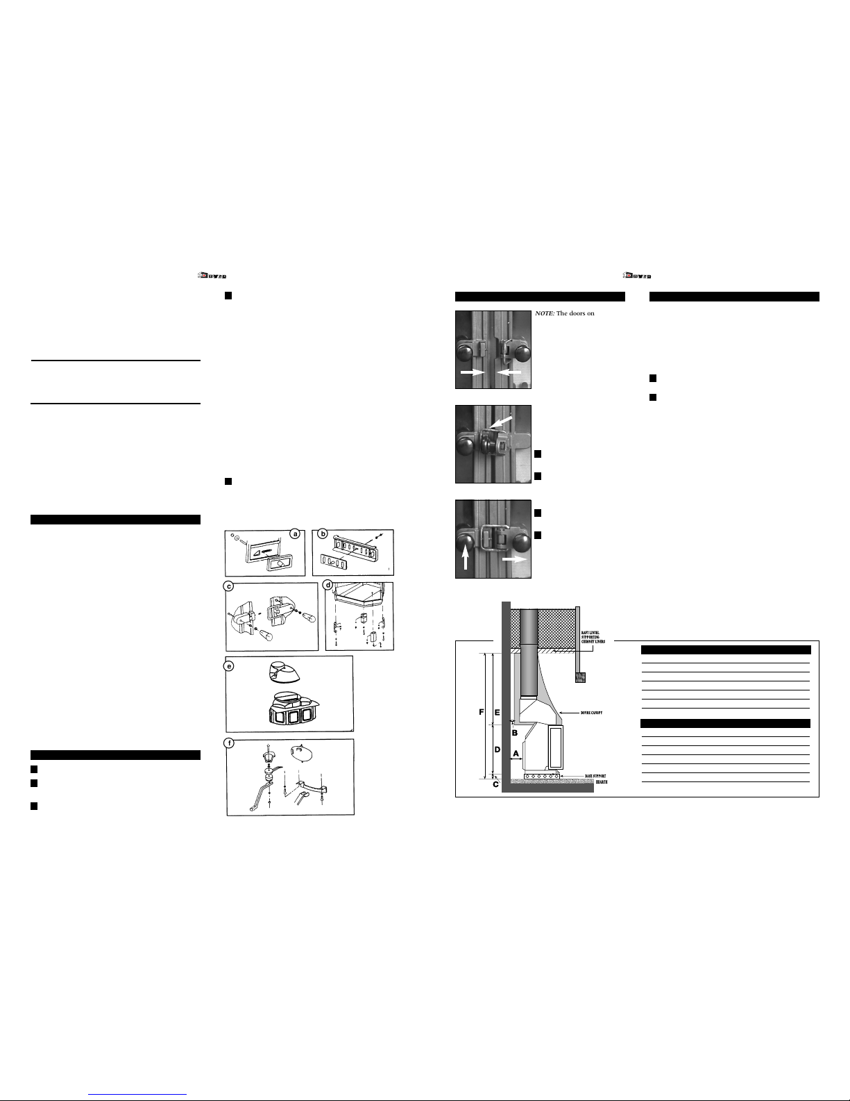
WHEN FITTED WITH CANOPY CM3 - CS3
MINI STANDARD SUPER
A* 100 100 100
B* 15 15 15
C 75 75 75
D 410 625 695
E 950 1070 1070
F 1435 1770 1840
WHEN FITTED WITH CANOPY CM2 - CS2
A* 100 100 100
B* 15 15 15
C 75 75 75
D 410 625 695
E 700 685 685
F 1185 1385 1455
* Minimum Dimensions. All Dimensions in Millimetres.
a
a
a
a
a
a
a
aa
a
aa
aaa
a
a
a
NOTE: The doors on your
Dovre 2000 have been
accurately fitted in our factory.
In case you do find a problem
in operating the doors, report
back to your dealer now. Do
not attempt to proceed with
the installation. Dovre can not
accept responsibility for
incorrect door alignment after
the appliance has been
installed. Refer to page 2 of
this manual.
IMPORTANT: The following
stages should be used when
closing the doors on your
Dovre 2000 stove
Pull both sets of doors
together (see fig1).
Locate right hand side
door catch over adjustable
grub screw on left hand
door (see fig2).
Holding door knob push
left hand door.
While maintaining
pressure on left hand door
use right hand door knob
to pull door towards you
at the same time bringing
both doors together
(see fig3).
1
2
3
4
Fig.1
Fig.2
Fig.3
Page 3

54
a
a
a
a
a
a
a
aa
a
aa
aaa
a
a
a
a
a
a
a
aa
a
a
aa
a
a
a
a
a
aa
aa
a
a
a
a
aa
a
a
a
a
a
a
a
a
a
a
a
a
a
a
a
aa
a
a
a
a
a
a
a
a
a
a
a
a
a
a
a
a
a
a
a
a
a
a
a
a
a
a
aa
a
a
a
a
a
a
a
a
a
a
a
a
a
a
a
a
a
a
a
a
a
a
a
a
a
a
a
a
aa
a
a
a
a
a
a
a
a
aaa
a
aa
a
a
a
a
aa
a
a
a
a
a
a
a
a
a
a
a
a
a
aa
aa
a
a
aa
a
a
a
a
a
a
a
a
a
aa
a
a
aa
a
a
aaa
a
a
a
a
a
a
a
a
a
a
a
a
a
a
a
a
a
a
a
a
a
a
a
a
a
a
a
a
a
a
a
a
a
a
a
a
a
a
a
a
a
a
a
a
a
a
a
a
a
a
a
a
a
a
a
a
a
a
a
a
a
a
a
a
a
a
a
a
a
a
a
a
aa
a
a
a
a
a
a
a
aa
a
a
a
a
a
a
a
a
a
aa
a
a
a
a
a
a
a
a
a
a
a
a
a
a
a
a
a
a
a
a
aaa
a
a
a
a
a
a
a
a
a
a
a
a
aa
a
a
a
a
a
a
a
aaa
a
a
a
a
a
a
a
a
aa
a
a
aa
a
aa
a
a
a
a
a
a
aa
a
a
a
a
a
a
a
aa
a
aa
aaa
a
a
a
aa
a
aaa
a
a
a
a
a
a
a
a
aa
a
aa
a
a
a
a
a
aa
a
aaa
a
a
aa
a
a
aa
a
a
a
a
a
aa
aa
a
a
a
a
aa
a
a
a
a
a
a
a
a
a
a
a
a
a
a
a
aa
a
a
a
a
a
a
a
a
a
a
a
a
a
a
a
a
a
a
a
a
a
a
a
a
a
a
aa
a
a
a
a
a
a
a
a
a
a
a
a
a
a
a
a
a
a
a
a
a
a
a
a
a
a
a
a
aa
a
aa
a
a
a
a
a
aaa
a
aa
a
a
a
a
aa
a
a
a
a
a
a
a
a
a
a
a
a
a
aa
a
a
a
a
aa
a
a
a
a
a
a
a
a
a
aa
a
a
aa
a
a
aaa
a
a
a
a
a
a
a
a
a
a
a
a
a
a
a
a
a
a
a
a
a
a
a
a
a
a
a
a
a
a
a
a
a
a
a
a
a
a
a
a
a
a
a
a
a
a
a
a
a
a
a
a
a
a
a
a
a
a
a
a
a
a
a
a
a
a
a
a
a
a
a
a
aa
a
a
a
a
a
a
a
aa
a
a
a
a
a
a
a
a
a
aa
a
a
a
a
a
a
a
a
a
a
a
a
a
a
a
a
a
a
a
a
aaa
a
a
a
a
a
a
a
a
a
a
a
a
aa
a
a
a
a
a
a
a
aaa
a
a
a
a
a
a
a
a
aa
a
a
aa
a
aa
a
a
a
a
a
a
aa
aaa
a
a
a
a
a
a
a
a
a
a
a
a
a
a
a
a
a
a
a
a
a
a
a
a
a
a
a
a
a
aaa
a
a
a
a
a
a
a
a
aaa
a
aaa
a
a
a
a
a
a
aaa
a
a
a
a
a
aa
a
a
a
a
a
a
a
a
a
a
a
aaa
a
a
a
a
a
a
a
a
aaa
a
a
a
a
a
a
a
aa
a
a
a
a
a
a
a
a
a
a
a
a
a
a
a
a
a
a
a
a
a
a
a
a
a
a
a
aaa
a
a
a
a
a
a
a
a
a
a
a
a
a
a
a
a
a
a
a
a
a
aaa
a
aa
a
a
a
a
a
a
a
a
a
a
a
a
a
a
a
a
a
a
a
a
a
a
a
a
a
a
a
a
aa
a
a
a
a
a
a
a
a
a
a
a
a
a
a
a
a
a
a
a
a
a
a
a
a
a
a
a
a
a
a
a
a
a
a
a
a
a
a
aa
a
a
aa
a
a
a
a
a
a
a
a
a
a
a
a
a
a
a
a
a
a
a
a
a
a
a
a
a
a
a
a
a
a
a
a
aa
a
a
aaa
a
a
a
aaaa
a
a
a
a
a
a
a
a
a
a
a
a
a
a
a
a
a
a
a
a
a
a
a
a
a
a
a
a
a
a
aa
a
a
a
a
a
a
a
a
a
a
a
a
a
aa
a
aa
aaa
a
a
a
a
a
a
a
aa
a
a
aa
a
a
a
a
a
aa
aa
a
a
a
a
aa
a
a
a
a
a
a
a
a
a
a
a
a
a
a
a
aa
a
a
a
a
a
a
a
a
a
a
a
a
a
a
a
a
a
a
a
a
a
a
a
a
a
a
aa
a
a
a
a
a
a
a
a
a
a
a
a
aa
a
aa
aaa
a
a
a
a
a
a
a
aa
a
a
aa
a
a
a
a
a
aa
aa
a
a
a
a
aa
a
a
a
a
aa
a
aaa
a
a
a
a
a
a
a
aa
a
a
aa
a
a
a
a
a
aa
aa
a
a
a
a
aa
a
a
a
a
a
a
a
a
a
a
a
a
a
a
a
aa
a
a
a
a
a
a
a
a
a
a
a
a
a
a
a
a
a
a
a
a
a
a
a
a
a
a
aa
a
a
a
a
a
a
aa
a
aa
aaa
a
a
a
a
a
a
a
aa
a
a
aa
a
a
a
a
a
aa
aa
a
a
a
a
aa
a
a
a
a
a
a
a
a
aa
a
aa
aaa
a
a
a
a
a
a
a
aa
a
a
a
a
a
a
a
a
a
aa
a
a
a
a
a
a
a
a
a
a
a
a
a
a
a
a
a
a
a
a
a
a
a
aa
a
a
a
a
a
a
a
a
a
a
a
a
aa
a
a
aa
a
a
a
a
a
a
a
a
a
a
a
a
a
aa
a
aa
aaa
a
a
a
a
a
a
a
aa
a
a
aa
a
a
a
a
a
aa
aa
a
a
a
a
aa
a
a
a
a
a
a
a
a
INSTALLATION
1
2
3
4
5
6
7
Figure 1
Figure 3
Figure 2
SIDE VIEW
MINI STANDARD SUPER
A* 100 100 100
B* 510 640 650
C* 1160 1420 1570
PLAN (TOP) VIEW
MINI STANDARD SUPER
A* 100 100 100
B* 510 640 650
C* 630 760 760
D* 350 420 430
E* 690 820 820
BUILT-IN INSTALLATIONS
The appliance is deigned to be built into a new or
existing chimneybreast installation to provide efficient
space heating with both radiant and convected heat.
There must be sufficient space in the fireplace recess to
allow air to circulate around to back, top sides and base
of the appliance.
The example fig 1 shows how your Dovre should be
installed in a chimneybreast recess for chimneybreasts
situated internally and externally.
The recess should be formed using an appropriately
designed raft lintel to support the existing structural
brickwork and chimney. The minimum clearances between
the appliance and walls are illustrated in figs 2 & 3.
PROCEDURE
Prepare the opening ensuring that adequate support
is provided for the chimney and existing
chimneybreast structure. A raft lintel, to form the top
of the convection chamber, should be constructed.
The lintel should be pre-formed with a clearance
hole of 200mm (for the 1800W series, the clearance
need only be 150mm or 180mm depending on the
diameter of the flue pipe) to allow the connecting
flue pipe to be installed. If the recess is too wide,
reduce the width using 75mm thick building blocks.
Line the top, sides and back of the recess (convection
chamber) using Dovre insulated panels. Fix the
panels to the brickwork (aluminium face outwards)
using masonry nails or other suitable fixings.
If the fireplace is located on an outside wall, install a
standard airbrick or Dovre air control damper (part
number ASI) at floor level. For fireplaces located on
inner walls, it will be necessary to bring an air
supply from under the floor.
AN AIR SUPPLY IS PARTICULARLY IMPORTANT IN
WELL-INSULATED ROOMS.
Stand the appliance in the recess and adjust the
levelling bolts on the bottom of the legs to ensure the
appliance is level and plumb.
Use a length of 316 grade 1mm thick stainless steel
flue pipe or other pipe which complies with Current
Building Regulations for the installation of solid fuel
burning appliances, connected from the flue spigot on
the appliance to the main chimney. See fig 2 page 4.
ENSURE THAT THE APPLIANCE DOES NOT DIRECTLY
SUPPORT THE WEIGHT OF THE MAIN CHIMNEY OR
CHIMNEY LINERS. THE FLUE LINERS MUST BE
SUPPORTED BY INDEPENDENT BRACKETS.
Construct the hearth making sure that the design and
structure complies with current Building
Regulations.
The finished hearth surface (e.g. hearth tiles) should
be approximately 6mm below the bottom of the
doors. See fig. 2 page 4.
Construct the facing wall of the fireplace, using a
lintel to support brickwork / masonry above the
appliance.
NEVER BUILD DIRECTLY ONTO THE APPLIANCE.
50mm thick lightweight building blocks backed
with Dovre insulation panels are ideal for
constructing the facing wall of the convection
chamber. See fig 2 & 3 page 4.
Install air grills, total minimum area 600sq.cm at the
highest point of the convection chamber. Install air
grills minimum area 400sq.cm as close to the floor
level as possible. There is no restriction on the
number of grills used.
Where the fireplace backs onto another room, or is
situated in the corner of the room, backing onto two
rooms, grills can be fitted in the adjacent rooms. In
this case, it will also be necessary to fit a return air
grill in the other room or rooms.
NEVER USE GRILLS MADE FROM PLASTIC OR
OTHER COMBUSTIBLE MATERIALS.
The model 2000MFR is available with an optional glass
lined boiler suitable for direct or indirect cylinders. The
system must incorporate gravity circuit open to
expansion. Pipework must be a minimum diameter of
28mm and must be installed to rise from the appliance.
IT IS RECOMMENDED THAT A QUALIFIED HEATING
ENGINEER IS USED TO INSTALL HOT WATER MODELS.
The chimney is the key to the successful installation of your
Dovre appliance. If the chimney is in poor condition or of
the wrong design or construction, the performance of the
appliance will be adversely effected and problems will be
experienced with combustion and possible smoke emission
to the room.
PLEASE SEEK THE ADVICE OF A CHIMNEY SPECIALIST IF IN
DOUBT.
The chimney should be one of the following types:
■ Brick built with suitable liner for use with
woodburning and solid fuel appliances.
■ Twin wall stainless steel approved for use with
woodburning and solid fuel appliances.
■ Prefabricated “concrete” type systems approved for
use with woodburning and solid fuel appliances.
DO NOT USE FLEXIBLE LINERS DESIGNED FOR USE
ONLY WITH GAS STOVES
CHIMNEY DIAMETER
MINIMUM 200MM (150MM FOR 1800)
INSIDE DIAMETER.
NEVER ALLOW THE APPLIANCE TO CARRY THE
WEIGHT OF THE CHIMNEY.
1800W SERIES / 2700W SERIES
Dry wood (minimum 2 years seasoned), Lignite briquettes
(brown coal), dry peat, Homefire.
2000MFR SERIES
Dry wood (minimum 2 years seasoned), Lignite briquettes
(brown coal), dry peat and most manufactured smokeless
fuels.
• Place tightly rolled newspaper or firelighters on the grate
of the appliance.
• Place a reasonable quantity of small pieces of dry kindling
wood on top of the newspapers and 3 or 4 pieces of wood
approx. 2.5 to 5cm in diameter on top of the kindling wood.
• Slide the lower and upper air controls to the fully open
position. (1800W is not equipped with upper air controls).
• Open the doors fully and light the front newspaper or
Firelighters with a long taper.
• Immediately after the kindling wood begins to burn,
partly close the doors leaving a distance of 2 - 3cm from the
fully closed position.
• Allow the fire to burn fiercely in order to warm the
chimney as quickly as possible. As soon as the fire is
burning well, add more wood or solid fuel.
• If burning solid fuels, the solid fuel may be placed directly
on the firelighters.
• Ideally your wood should be no more than 10cm diameter.
MODELS WITH BACK BOILERS
THE CHIMNEY
FUELS
LIGHTING AND OPERATION
Page 4

76
The lower air controls (located at the bottom of the doors)
and the upper air controls (located at the top of the doors)
should be fully open until the fire is established. Closing
the air controls while the fire is cold will cause fast
sooting up of the door glass and chimney.
When the fire is well established, operate as follows:
MODEL 1800W
Operate the heat output by adjustment to the air controls
located at the bottom of the doors.
MODEL 2700W
For woodburning, leave both the top and the bottom air
controls fully open. When a hot fire is established, close
the bottom air controls. The burning rate can then be
controlled by adjustment to the top air controls. When
burning solid fuels on the 2700W, the above is reversed
and the burning rate is controlled by adjustment to the
lower air controls.
MODEL 2000MFR
For woodburning, leave both the top and the bottom air
controls fully open. When a hot fire is established, close
the bottom air controls. The burning rate can then be
controlled by adjustment to the top air controls. When the
appliance is used with the doors in the open position (as
an open fireplace) the burning rate can be controlled by
adjusting the front air slide control in front of the ash
compartment.
For overnight burning, fully close the lower air control
and partly close or fully close the top air controls (if
fitted).
IMPORTANT
NEVER ALLOW THE GRATE TO BECOME
“SANDWICHED” IN ASH. THE UNDERSIDE OF THE
GRATE MUST NEVER BE IN CONTACT WITH ASH.
FAILURE TO OBSERVE THIS ADVICE WILL LEAD TO
PREMATURE WEAR OF THE GRATE.
CONTROLS CARE OF YOUR DOVRE APPLIANCE
The Dovre 2000 is constructed from high quality cast iron
and finished with a special high temperature resistant
paint. To ensure a good appearance is maintained, the
cast iron surfaces should be brushed using a soft clean
brush. Never attempt to clean the stove whilst it is under
fire. One a year, the doors can be treated with a new coat
of paint using Dovre high temperature resistant paint
available from your stockist.
GLASS
Clean the glass daily whilst the glass is warm (not hot).
Use a damp soft cloth with a little mild detergent. Never
use harsh abrasives. If the glass is coated with heavy tar
deposits, use Dovre Ceraclean glass cleaner. Never allow
excessive tar deposits to build up.
DOVRE 2000 GAS MODELS
If fitting a DOVRE gas burner to your Dovre 2700W,
please refer to the separate installation instructions
issued with the burner.
It is important that you also ensure that following steps
are taken if a gas burner is fitted.
Remove any flue damper that may be fitted to the
appliance.
Ensure that the appliance doors are locked in the “open
position”
ANNUAL MAINTENANCE
TROUBLESHOOTING
Remove the rope seals from the doors.
Clean out rope channels using a wire brush.
Fit new Dovre rope seal using the special adhesive
supplied in the Dovre Service Kits (these can be
obtained from your Dovre stockist).
Lightly grease all hinges on doors with graphite
grease.
1
2
3
4
SMOKE ENTERING ROOM FROM
APPLIANCE
TAR FORMATION
FUMES ENTERING ROOM
THROUGH AIR GRILLS
CAST IRON GRATES DISTORTING
■ If burning wood, make sure it is well seasoned with moisture content well below 20%. This
usually requires the wood to be seasoned for 2-3 years. Trying to burn “green wood” is like
trying to burn water!
■ Ensure you are not closing the air controls before the fire is established (see section on
operation).
■ Check for blockage in chimney (consult your chimney sweep if necessary).
■ If problems persist, arrange for your dealer or professional chimney specialist to report on the
suitability of your chimney.
■ Use of unseasoned wood.
■ Poor chimney draught.
■ Operating appliance while the fire is at very low temperature.
■ Seals on flue joints in convection chamber are not “smoke tight”.
■ Walls of convection chamber are not clean.
■ Ash compartment over full causing the grates to be sandwiched in hot ash.
PROBLEM CAUSE OF PROBLEM
✁
Please complete and return this section within seven days of purchase to:
Dovre Castings Ltd, Weston Works, Weston Lane, Tyseley, Birmingham B11 3RP.
NAME:
ADDRESS:
TELEPHONE NUMBER:
MODEL:
DATE OF PURCHASE:
DEALER:
DOVRE 10 YEAR WARRANTY
If the castings on this appliance should prove to be defective within ten years of the
purchase date, the faulty castings will be replaced free of charge, subject to the
following conditions.
1. The purchaser shall complete the registration section below and return it within
seven days of purchase. Failure to return the registration could result in delays in
processing any claims.
2. The appliance shall have been installed in compliance with the installation
instructions.
3. The appliance shall not have been used for the burning of unseasoned wood.
4. This warranty only applies to the appliance body castings and does not include
renewable components including grates, ashpans, glass, seals and baffle plates.
5. This warranty does not cover site visits and labour charges.
This warranty does not affect the Statutory Rights of Consumer Purchasers.
Page 5

Unit 1, Weston Works, Weston Lane, Tyseley, Birmingham B11 3RP.
Tel: 0121 706 7600. Fax: 0121 706 9182.
E-mail: enquiries@dovre.co.uk
Web site: www.dovre.co.uk
 Loading...