

Page 1
LIMITED WARRANTY
The manufacturer agrees that its products shall be free from
ping advice, buyer may return it directly to Dove Systems, San
age in case of any failure to meet the conditions of any warranty of
shipping schedule, nor will claims for labor, loss of profits, repairs,
pressed or implied, are made by the manufacturer in connections
defects in material or workmanship over a period of one year from
date of shipment from the factory. Said warranty will not apply if
equipment is used under conditions of service for which it is not
specifically intended. The manufacturer is not responsible for damage to its apparatus through improper installation, physical damage, or poor operating practice.
If any device is found unsatisfactory under the warranty,
the buyer should notify the manufacturer, and after receipt of ship-
Luis Obispo, CA, shipping prepaid. Such equipment will be replaced or put in proper operating condition, free of all charges except transportation. The correction of any defects by repair or
replacement by the manufacturer shall constitute fulfillment of all
obligations to the purchaser. Manufacturer does not assume
responsibility for unauthorized repairs to its apparatus, even
though defective.
Manufacturer shall not be liable for any consequential dam-
or other expenses incidental to replacement be allowed.
No other representation, guarantees or warranties, ex-
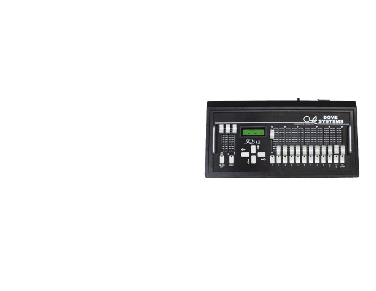
IQ512
12 Channel DMX controller
with the manufacture and sale of its equipment. This warranty is
non-transferable and applies to the original buyer only.
© 2001
Dove Lighting Systems, Inc.
010914
8
Dove Lighting Systems, Inc.
3563 Sueldo Street, Suite E
San Luis Obispo, CA 93401 USA
Phone +1 805 541 8292
Fax +1 805 541 8293
www.dovesystems.com
1
Page 2

Contents
Setting Default Patch.............................................................................................5
Patching Dimmers to Channels..............................................................................6
to selecting dimmers. Select the dimmer you wish to control (using
the up and down keys). Use the right arrow to move over to setting
ate control channel slider to full. For example, if you are building a
output of the IQ512 will follow the adjustments as you make them.
Introduction............................................................................................................3
Quick Start.............................................................................................................3
Making A Scene!...................................................................................................4
Lights Out!.............................................................................................................4
Using the Menu......................................................................................................5
Clearing the Patch Table........................................................................................5
Patching Channels To Dimmers............................................................................6
LIMITED WARRANTY.......................................................................................8
Patching dimmers to channels also allows you to “set a
look” on a control channel. To do this, select Edit Patch Table ->
patch channel @ dimmer @ level. To set the first “look” on channel 1, leave channel 1 selected. Use the right arrow to move over
levels. Use the up and down keys to adjust the level of this dimmer. Once this dimmer is set, use the left key to move back to selecting dimmers. Use the up and down keys to select the next
dimmer to set. Use the right arrow key to move over to setting levels. Again, use the up and down keys to set the level. Repeat this
until the “look” for this channel is set. You can then either use the
left key to get out of the menu, or use the right key to move to the
next control channel.
You can watch the look being built by setting the appropri-
look on channel 1, set the channel 1 slider to full. As you patch
dimmers to channel 1, you’ll see the effect on stage. The DMX
When you start building the look for channel 2, bring channel 1 to
zero and set channel 2 to full.
2
7
Page 3

Patching Channels To Dimmers
Press the right arrow key to select Patch dimmer @ channel
using the up and down arrows. Press the up arrow to select a higher
patch is finer than that of the display. It may, at times, take two or
♦
Once all patch assignments are set, press the left key to exit
Patching dimmers to channels is just like patching channels
the IQ512 lets you patch the way
you
want to patch. The procedure
controller. Each control channel may be proportionally patched out
to 512 DMX channels (dimmers). The IQ512 also includes a grand
The patching capability may also be thought of as a submaster
ideal for television applications where one look may light the news
all the way down. Connect the supplied power supply ("wall wart")
To patch channels to dimmers, follow these steps:
♦ Press the right arrow key to enter the menu. The display
will say "Edit Patch Table."
♦ Press the right arrow key to select Edit Patch Table. The
display will say "Patch dimmer @ channel @ level."
♦
@ level. The display will say “dimmr@chan@level” on the first
line, and “> 01 @ 01 @ 100%” on the second line. The ">" before
the "01" indicates we can change the dimmer we are patching to
dimmer number and the down arrow to select a lower dimmer
number.
♦ Once the dimmer you want to patch is selected, press the
right arrow. The ">" moves to being in front of the channel number. Use the up and down arrows to select the channel this dimmer
is to be patched to.
♦ Once the appropriate channel is selected, press the right
arrow key. The ">" moves to being in front of the level to be used
in this proportional patch. Use the up and down arrow keys to set
the level in percent. Note that the patch proportion is a full 8 number (where 0 correspond to zero and 255 corresponds to full). The
display, however, is in percent. The result is the resolution of the
three key clicks to increase or decrease the level by one percent.
Each key click is making a change of about 0.4%.
♦ Once the patch level is set, you can hit the left key to go
back and set up another channel, or hit the right key to move to the
next dimmer.
the menus.
Patching Dimmers to Channels
to dimmers, only backwards! It’s all a matter of perspective, and
Introduction
The IQ512 is a "single scene with hold" 12 channel DMX
master control, blackout switch, and channel bump buttons.
The "single scene with hold" turns this compact controller
into a two scene controller with split dipless crossfaders, making it
ideal for small theatre applications. Patching allows each control
channel to control any or all of the 512 dimmer channels. This allows the IQ512 to be used in "dimmer per fixture" installations.
One control on the IQ512 may control hundreds of dimmer channels.
capability. By patching dimmers at specified levels to a channel,
the user can establish a "look" on that control channel. In this
application, the IQ512 can hold 12 "looks." This makes the IQ512
anchor desk, another may light the weather set, another may light
sports, and another may light the newsroom for that "breaking
story" look.
The IQ512 - A small controller with big capabilities.
Quick Start
The IQ512 ships with a default one-to-one patch. Control
channel 1 drives DMX channel (dimmer 1). Control channel 2
drives dimmer 2, etc. Use a standard DMX cable to connect the
IQ512 to your dimmer system. Slide the left sliders (GM, X, and
Y) all the way up. Slide the right sliders (channels 1 through 12)
to the IQ512 and an electrical outlet.
The display on the IQ512 should say "IQ512,
dovesystems.com". Slide each of the channel sliders up and down
to verify they are controlling dimmers 1 through 12. Press each of
the "bump buttons" below the channel sliders. The appropriate
light on the dimming system should flash to full.
You're controlling lights!
is almost identical to above, but channels and dimmers are reversed on the display.
6
3
Page 4

Making A Scene!
press the hold button. The hold button lights and the display says
next scene, move the X and Y crossfaders all the way down, fading
"live." To set up a new scene, hit hold again, set the new look, then
menu. The up and down arrows scroll through menu selections. To
patch table). The display will say "Confirm Load Default Patches."
patch table. The display will then say "Load default patch table."
On power up, the X and Y crossfaders should be all the
way up to make the channel faders live. To set the next scene,
"HOLD MODE, Move Xfaders Down". Don't move the crossfaders yet! Adjust the channel faders to the settings for the next scene.
The lights on stage will not change. When it is time to move to the
into the new scene. The X scene is always the "old" held scene,
while the Y scene is the scene you are bringing up. With this in
mind, it's possible to delay the fade out of the old scene or to delay
the fade in of the new scene (perhaps even doing a fade to black
between scenes) by delaying the motion of the X or Y crossfader.
Experiment with it a bit to see how it works. In most applications,
you can just grab both X and Y crossfaders and move them together.
Once the crossfaders have been moved to the down position,
the hold button goes out and the display returns to the normal
IQ512 display. At this point, the channel sliders are once again
move the crossfaders up.
The general sequence is: hit hold, set up scene, move crossfaders down. Hit hold, set up scene, move crossfaders up. Repeat
as necessary.
Using the Menu
The setup menu in the IQ512 is modeled after the Lynx web
browser. The right arrow key "follows a link" or takes you further
into a menu selection. The left arrow backs you out of the current
enter the menu, hit the right arrow key.
Setting Default Patch
After messing with patching, you may want to restore the default one-to-one patch. To restore the default patch, follow these
steps:
♦ Press the right arrow key to enter the menu.
♦ Press the down arrow key until the display says "Load de-
fault patch table."
♦ Press the right arrow to select this option (load default
♦ Press the right arrow to confirm that you want to load de-
fault patches. The display will show the model number and software revision. It will then test the memory that holds the patch
table, clear the patch table, and load the default values into the
You can hit the left arrow key to exit the menu or an up or down
key to choose another menu option.
Lights Out!
You can instantly black out all lights by hitting the blackout
button. The display will say "Blackout Enabled," and the blackout
button will flash. Hit the blackout switch again to bring the lights
back to their previous levels.
You can "fade to black" using the GM (Grand Master) control. Sliding the GM control down dims all lights proportionally
until they are out. When the GM control has turned off all the
lights, the blackout switch will light and the display will say
"Grand Master = 0." Slide the control back up to fade the lamps
back up.
4
Clearing the Patch Table
Prior to putting in your own patch settings, it's nice to start
with an empty patch table. Follow these steps:
♦ Press the right arrow key to enter the menu.
♦ Press the down arrow key until the display says "Clear
Patch Table."
♦ Press the right arrow key to select this option (Clear Patch
Table).
♦ The display will say "Confirm Clear Patch Table."
♦ Press the right arrow key to confirm that you want to clear
the patch table. The display will say "Clearing Patch Table," then
say "Clear Patch Table."
♦ Press the left arrow key to exit the menu or the up or down
keys to select another menu option.
5
 Loading...