

Page 1

TABLE OF CONTENTS
OWNER'S MANUAL
DIMMERMASTER 1224
DIGITAL DIMMER
DM1224 Rev. 1.11 04/28/99
Dove Systems
3563 Sueldo Street Unit E
San Luis Obispo, CA 93401
(805)541-8292
fax (805)541-8293
dove@dovesystems.com
www.dovesystems.com
PAGE
1) SETUP AND CONNECTION 1
A) Mechanical Installation 1
B) Rack Mounting 1
C) Electrical Installation 1
D) Grounding 1
E) Load Connections 2
F) Control Connections and Overtemp Sensing 2
G) Channel Selection and Testing 3
H) Indicators 3
2) TROUBLESHOOTING CHART 3
3) WARRANTY INFORMATION 4
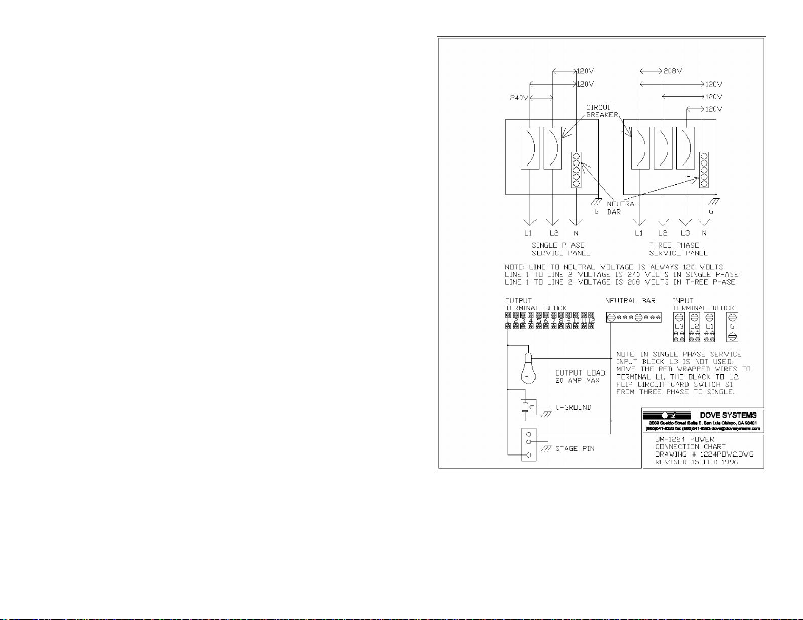
4) POWER CONNECTION CHART 5
Page 2

1. SETUP AND CONNECTION
A) MECHANICAL INSTALLATION
just to the right of the power block. The pack has circuit breakers to protect
each dimmer channel, but the primary circuit protection and disconnect is to
be provided by the user.
Remove all packing material from the unit. Make certain that all holes are
free of obstruction on all sides of the unit. Replace all packing material in the
carton and store it for reuse.
For portable use, set the Dimmermaster on a smooth, cool surface. Up to 2
packs may be stacked vertically. Do not remove the feet when stacking. Do
not block any vent holes. Make certain that the vent holes all have at least 6
inches of free air around them. It is essential that this unit have adequate
cooling for safe, reliable performance. Maximum air temperature must not
exceed 40E Centigrade (105E Fahrenheit).
B) RACK MOUNTING
The Dimmermaster may be rack mounted in a standard EIA 19-inch equipment
rack. The rubber feet may be removed. Do not remove the top and bottom panels.
The Dimmermaster occupies 5.25 inches of space in the rack, or three rack units.
For best cooling, an additional 1.75 inches, or one rack unit, between packs is
recommended. The rack should be ventilated from the top at a minimum of 120
CFM.
C) ELECTRICAL INSTALLATION
The dimmer must be supplied with an amount of current equal to the combined
total current of the lamps it controls. To calculate this current, use the formula
amps = watts ÷ volts. For example, if twelve 2400-watt, 120 volt lighting units are
connected to the dimmer, it would require 28,800 ÷ 120, or 240 amps total power.
This is available from a three phase 4 wire 80 amp or a single phase 3 wire 120
amp service. Usually this much power is not required and a 40 - 60 amp service
may be used with lower power loads plugged in.
When single phase service is used switch S2, located near the center of the
board, must be moved from the "3 phase" position to the 1 phase4" position.
The power input terminal marked "L3" is not used. The two blue wires wrapped
with red tape must be moved to the terminal marked "L1" and the two wrapped
with black tape to "L2". The tiny blue wire stays in terminal "L3". Please refer to
the diagrams at the rear of this manual.
D) GROUNDING
The term GROUNDING refers to a separate wire with green insulation which
is connected from the equipment case to earth ground (often through a properly
grounded conduit system). This is not the same as the neutral or common and
must not be confused with them. The neutral is a separate, load-carrying circuit
conductor. The ground conductor should not normally carry current.
When the Dimmermaster is connected to its power source by a flexible rubber
cable, the ground connection is made through a wire in the cable. For maximum
safety and to comply with electrical codes, this connection must be made. Cables
supplied by Dove Systems are pre-wired for this connection and include the
necessary green wire. Be sure this is firmly bonded to a ground connection box,
a cold water pipe, or a known earth ground.
When the Dimmermaster is connected to its power source by conduit, the
ground connection can be made via the conduit itself. If flexible conduit is
used, a separate bonding conductor will usually be required. Always check
your local codes for hook-up before operating this equipment. It is recommended
that power connections to the Dimmermaster be made by a qualified electrician.
E) LOAD CONNECTIONS
The Dimmermaster accepts either three phase or single phase power input
and is factory configured for three phase. Line to neutral voltage is always
120 volts. Line 1 to Line 2 voltage is 208 volts in three phase service and 240
volts in single phase service. It is very important that the input voltages be
checked with a meter to insure that they are correct. A mistake can place 208
to 240 volts across a 120 volt lamp. The breakers will protect the unit but
may not save the lamps. A double check of voltages before applying power
can guard against such disaster.
The power input connector is a terminal block. Each leg of the power feed
connects to one terminal on the dimmer pack. These are marked "L1", "L2",
and "L3". The neutral connection is made on the neutral bar, just to the left
of the power block. The ground connection is made on the ground terminal,
The dimmer pack consists of twelve dimming channels. The Dimmermaster
will dim any load from 1 watt through 2400 watts at 120 volts. The load may
be incandescent, inductive, or resistive. This includes conventional incandescent,
quartz incandescent, rain-lights, pin beams, and similar lamp loads. This does not
include fluorescent or neon lamps. Dove Systems offers a solid state transformer
to dim other types of loads, such as 12 volt MR16 lamps.
The output connectors can be U-ground receptacles, stage pin receptacles,
twist-lock receptacles (L5-20R), or a terminal block. If your unit has receptacles
installed, merely plug the load into the outlet which corresponds to the circuit you
desire to use. For terminal-block-only units, there is one lug for each output and
a neutral bar for all neutrals. Lugs are numbered according to their circuits. There
should be a separate neutral returning from each load circuit.
Page 3

F) CONTROL CONNECTIONS AND OVERTEMPERATURE SENSING
is 37, the pack reads control signals for channels 37 through 48.
The Dimmermaster 1224 can take either of two control protocols: USITT
DMX-512 or 0 to +10VDC analog. DMX control input connections are made
through the five pin male XLR on the front of the unit. Analog 0 to +10VDC
control input connections are made through the DB15 male on the front of
the unit.
XLR DB15
DMX ANALOG
PIN 1 Common PIN 1 Channel 1 PIN 9 Channel 9
PIN 2 Data PIN 2 Channel 2 PIN 10 Channel10
PIN 3 Data PIN 3 Channel 3 PIN 11 Channel 11
PIN 4 -DataReturn PIN 4 Channel 4 PIN 12 Channel 12
PIN 5 +DataReturn PIN 5 Channel 5 PIN 13 +15V unregulated
PIN 6 Channel 6 PIN 14 -15V unregulated
PIN 7 Channel 7 PIN 15 Common
PIN 8 Channel 8
DMX pins 4 and 5 return the status of the dimmer to the controller. An option
on the dimmer sends the heat sink temperature and each of the line currents
back to the controller for display.
When the temperature of the heatsink exceeds 75E Celsius, the control is cut
off. This prevents overheating. When the heatsink cools, the loads begin to
work again. If this happens, the air circulation around the dimmer should be
improved. Check that the internal fan has not failed. Note that the fan does
not opeate until the heatsink temperature exceeds 50E Celsius.
When the first digit of the thumbwheel switch reads "6", the pack is in load
testing mode. The second and third digits show the dimmer being tested,
from 1 to 12. The load test forces the output of the dimmer to full. This is
helpful for focusing and troubleshooting. (e.g. Which channel is that? Is the
lamp burnt out?) In addition, setting the thumbwheel switch to "600" powers all
loads at approximately 20%.
H) INDICATORS
The status indicator LED is used to check the Dimmermaster for proper
control and power connections. It shines amber or green when it is receiving
power and a valid DMX signal, and red when it is receiving power but a bad
signal. It also shines red when it is receiving an analog signal only. No light
at all means that it is not receiving power.
I) INTERNAL SWITCHES
A 9 position internal DIP switch sets various options. These include DMX
line termination and nondim operation. DIP switch functions are printed on
the circuit board.
To terminate the DMX line (this is the last dimmer in the DMX string), turn
on DIP switch number 1 (which terminates DMX pins 2 and 3) and 9 (which
terminates DMX pins 4 and 5).
G) CHANNEL SELECTION AND TESTING
The thumbwheel switch on the front of the unit is the channel selection switch.
The number shown is the starting dimmer. Valid starting dimmer numbers
range from 1 to 501. The starting dimmer number determines the setting for
the entire pack of twelve dimmers. If, for example, the starting dimmer number
All outputs at or above a specified number may be set to nondim. When
set to nondim, an output is full when fed with 50% (DMX level 128, analog
+5V). or higher. Below this threshold, the output is off. The first nondim output
is set using binary coding on the DIP switch. For example, if outputs 7 and
above are to be nondim, switches 2, 3, and 4 would be set to the on position,
since these correspond to nondim 1, nondim 2, and nondim 4. 1+2+4=7, so
outputs 7 and above will be nondim.
2. TROUBLESHOOTING CHART
SYMPTOM: No channels work; no lights at all.
Possible cause: Action to take:
*Improper pinout on controller or cable wires Check pinout. Check
Page 4

cable.
reversed
*Control console incorrectly set up Reread operating instructions;
check setup &
protocol on console.
*Defective 1224 control card Replace Control Card
Assembly.
*Thermostat has opened Improve air circulation or reduce
loads. Check internal
fan. Unit will start working
when cool.
SYMPTOM: One or more channels are out.
Possible cause: Action to take:
*No load connected or lamp Check instrument in
known
burned out good outlet.
*Channel breaker is tripped Check load, reset
breaker.
*Power wire not connected Check for proper phasing
on power wiring
*Test switch in load test mode Select proper starting
channel
SYMPTOM: Channels 9 & 10 and/or 11 & 12 are stuck on or off or work
backwards
Possible cause: Action to take:
*Incorrect power wiring or switch setting Check power wiring and
switch S2
SYMPTOM: Some channels flicker
Possible cause: Action to take:
*Intermittent connection in Recheck all connections.
control or load lines
*SCR or control circuit failure Replace SCR module or
card
*Slide controls are broken Have slide control
replaced. Treat temporarily
or dirty with WD-40 or
Tri-flo
TO CHANGE AN SCR MODULE OR SSR: 1. DISCONNECT POWER
FROM DIMMER. 2. REMOVE FIVE SCREWS BINDING TOP PANEL TO
SIDE PANELS AND BACK. 3. REMOVE CONNECTIONS FROM THE
SUSPECT SCR MODULE. THERE ARE SIX MODULES WITH TWO
CHANNELS IN EACH. THE MODULE CLOSEST TO THE FAN IS
CHANNELS 1 AND 2. 4. REMOVE SCREWS BINDING MODULE TO
HEAT SINK AND REPLACE MODULE. 5. REASSEMBLE IN REVERSE
ORDER OF DISASSEMBLY.
TO CHANGE THE CIRCUIT CARD: 1. DISCONNECT POWER FROM
DIMMER. 2. UNSCREW FOUR SCREWS HOLDING CIRCUIT BOARD
PANEL TO FRONT PANEL. 3. SLIDE CARD OUT. SET JUMPERS AND
SWITCHES ON REPLACEMENT CARD TO MATCH. 4. SLIDE
REPLACEMENT CARD IN UNTIL IT SEATS INTO EDGE CONNECTOR
AND SCREW DOWN.
SYMPTOM: Channel breaker keeps tripping.
Possible cause: Action to take:
*Shorted cord or fixture Clear fault and reset
breaker.
*Channel overload Reduce wattage
connected and reset breaker.
SYMPTOM: One or more channels are up full and won't dim.
Possible cause: Action to take:
*SCR failure Replace SCR module.
*Control console incorrectly set up Reread the operating instructions
(Unplug control line to verify) of console
*Test switch in load test mode Select proper starting
channel
Users with further technical questions may call the factory at (805) 541-8292.
NOTE: DOVE SYSTEMS DIMMER PACKS USE TRADE SECRET AND
PROPRIETARY CIRCUITY. FOR THIS REASON, SCHEMATICS CANNOT BE
RELEASED FOR THIS PRODUCT. To obtain service, pack the unit with the
original packing materials or crushed newspaper and return it, freight prepaid, to:
Dove Systems (Repair process is expedited when you
3563 Sueldo Street Unit E include a note describin the problem;
San Luis Obispo, CA 93401 your return UPS shipping address.)
USA
Page 5
3. WARRANTY INFORMATION
The manufacturer agrees that the Dimmermaster 1224 shall be free from defects
in material or workmanship from date of shipment over a period of one year. Said
warranty will not apply if equipment is used under conditions of service for which
it is not specifically intended. The manufacturer is not responsible for damage to
its apparatus through improper installation, physical damage, or poor operating
practice.
If any device is found unsatisfactory under the warranty, the buyer should notify the
manufacturer, and after receipt of shipping advice, buyer may return it directly to
Dove Systems, San Luis Obispo, CA, shipping prepaid. Such equipment will be
replaced or put in proper operating condition, free of all charges except
transportation. The correction of any defects by repair or replacement by the
manufacturer shall constitute fulfillment of all obligations to the purchaser.
Manufacturer does not assume responsibility for unauthorized repairs to its
apparatus, even though defective.
Manufacturer shall not be liable for any consequential damage in case of any
failure to meet the conditions of any warranty of shipping schedule, nor will claims
for labor, loss of profits, repairs, or other expenses incidental to replacement be
allowed.
No other representations, guarantees or warranties, expressed or implied, are
made by the manufacturer in connection with the manufacture and sale of its
equipment. This warranty is non-transferable and applies to the original buyer
only. Copyright Dove Systems
1994
 Loading...