

Page 1
The Hornet™ pump was specifically designed for industrial
and general commercial use. This pump can be applied to
chemical transfer and dispensing, automotive recycling and
cleaning, and car wash systems. The bolted configuration
ensures total product containment while the liquid path
design maximizes the output and efficiency. Offered with
a polypropylene wetted material, Wilden’s Hornet™ pump
provides the reliability, flexibility and efficiencies needed
in today’s demanding applications.
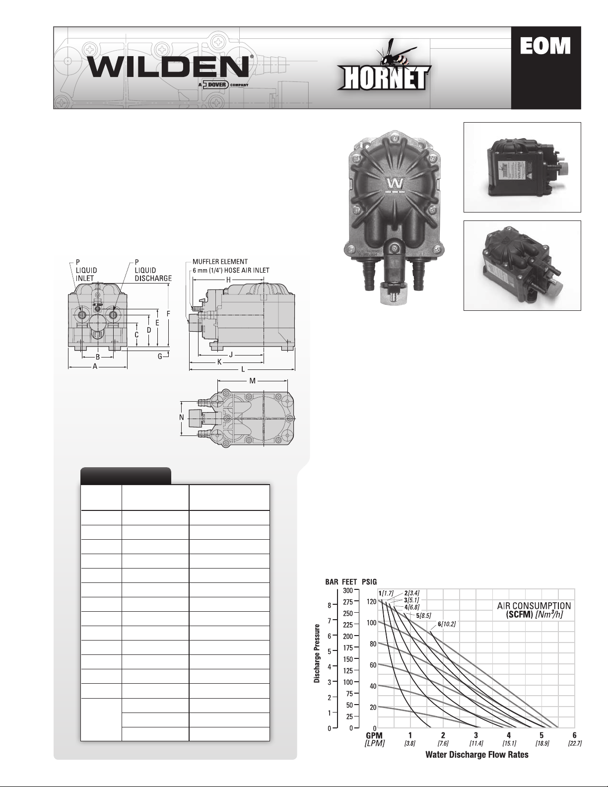
DIMENSIONS
ITEM
A 97 3.8
B 51 2.0
C 38 1. 5
D 51 2.0
E 61 2.4
F 104 4.1
G 8 0.3
H 117 4.6
J 107 4.2
K 122 4.8
L 173 6.8
M 114 4.5
N 56 2.2
P
METRIC (mm) STANDARD (inch)
10
10
13
3/8”
3/8”
1/2”
MNPT
HOSE
HOSE
HU38
HU100
Engineering
Operation &
Maintenance
TECHNICAL DATA
Height . . . . . . . . . . . . . . . . . . . . . . . . . . . . . . . . . . . . . 112 mm (4.4”)
Width. . . . . . . . . . . . . . . . . . . . . . . . . . . . . . . . . . . . . . . 97 mm (3.8”)
Depth. . . . . . . . . . . . . . . . . . . . . . . . . . . . . . . . . . . . . . 173 mm (6.8”)
Est. Ship Weight . . . . . . . . . . . . . . Polypropylene 0.9 kg (2.0 lbs)
Air Inlet - Hose. . . . . . . . . . . . . . . . . . . . . . . . . . . . . . . . 6 mm (1/4”)
Liquid Inlet . . . . . . . . . . . . . . . . . . . . . . . . . . . Hose – 10 mm (3/8”)
Hose – 13 mm (1/2”)
MNPT – 10 mm (3/8”)
Liquid Discharge . . . . . . . . . . . . . . . . . . . . . . Hose – 10 mm (3/8”)
Hose – 13 mm (1/2”)
MNPT – 10 mm (3/8”)
Suction Lift . . . . . . . . . . . . . . . . . . . . . . . . . . . . . . . 3.3 m Dry (10.9’)
9.3 m Wet (30.6’)
Max. Flow Rate . . . . . . . . . . . . . . . . . . . . . . . . . 20.8 lpm (5.5 gpm)
NOTE: Do not exceed 8.6 bar (125 psig) gas or air supply
DIMENSIONS
pressure. Flow rates indicated were determined by pumping
water with HU100 model.
PERFORMANCE
Page 2
CAUTIONS – READ FIRST!
CAUTION: Do not apply compressed air or gas to the
exhaust port – pump will not function.
CAUTION: Do not lubricate air supply. Excess
lubrication will reduce pump performance. Pump is
pre-lubed and does not require in-line lubrication.
TEMPERATURE LIMITS:
Polypropylene
0.0°C to 79.4°C (32°F to 175°F)
Wil-FlexTM (Santoprene®)
–40.0°C to 107.2°C (–40.0°F to 225°F)
CAUTION: When choosing pump materials, check
the temperature limits for all wetted components.
Example: Wil-Flex™ has a maximum limit of 107.2°C
(225°F) but polypropylene has a maximum limit of
only 79.4°C (175°F).
CAUTION: Maximum temperature limits are based
upon mechanical stress only. Certain chemicals
will significantly reduce maximum safe operating
temperatures. Consult Wilden’s Chemical Resistance
Guide for chemical compatibility and temperature
limits.
CAUTION: Do not exceed 8.6 bar (125 psig) air or gas
supply pressure.
CAUTION: If used with CO2 or N2 be sure the area is
well ventilated.
WARNING: Do not pump gasoline or flammable
liquids or use where flammable vapors are present.
CAUTION: Process fluid and cleaning fluids must
be chemically compatible with all wetted pump
components. Consult Wilden’s Chemical Resistance
Guide for chemical compatibility.
CAUTION: Always wear safety glasses when operating
pump. If diaphragm rupture occurs, material being
pumped can be forced out air exhaust.
CAUTION: Before removing pump from application,
the compressed air line to the pump should be
disconnected and all air pressure allowed to bleed
from pump. Disconnect all intake, discharge and air
lines. Drain the pump by turning it upside down and
allowing any fluid to flow into a suitable container.
NOTE: Tighten all hardware prior to installation.
NOTE: Wilden’s Hornet™ pump cannot be used in
submersible applications. If your application requires
a submersible pump, contact your authorized Wilden
Distributor for an alternative pump model.
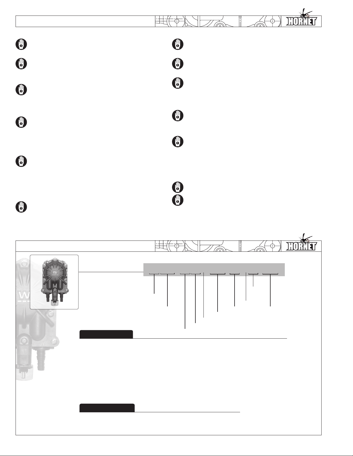
PUMP DESIGNATION SYSTEM
LEGEND
HORNET
PUMP
MATERIAL CODES
PUMP SIZE
38 = 10 mm (3/8”)
100 = 13 mm (1/2”)
WETTED PARTS & OUTER PISTON
PZ = POLYPROPYLENE/NO PISTON
CENTER SECTION
PP = POLYPROPYLENE
SPECIALTY CODES
HU XXX / XX X XX / XXX / XX/ XXX/ xxxx
FITTING
O-RINGS
CHECK
TM
PUMP SIZE
AIR VALVE
CENTER SECTION
WETTED PARTS & OUTER PISTON
AIR VALVE
E = POLYETHYLENE
DIAPHRAGMS/O-RINGS
WBL = WIL-FLEX™ (Santoprene®)
w/BUNA BACK-UP O-RING,
IPD (cream)
CHECK VALVE
WF = WIL-FLEX™ (Santoprene®)
CHECK VALVE
DIAPHRAGMS
VALVE
SPRING
CHECK VALVE SPRING
H = ALLOY C
MANIFOLD/FITTING O-RING
WF = WIL-FLEX™ (Santoprene®)
SPE CIALT Y
CODE
(if applicable)
No specialty code - MNPT Connection (note: only available for 10mm (3/8”) at this time)
0645 - Fitting, Hose Barb Connection
Page 3
SUGGESTED INSTALLATION
Wilden’s Hornet™ pump is designed to meet the
performance requirements of even the most demanding
pumping applications. Designed and manufactured to
the highest standards, this pump is well suited for general
commercial and industrial applications. Refer to the
performance information in this manual for an in-depth
analysis of the performance of your pump.
HOSE CONNECTIONS: Use flexible suction and discharge
hose ONLY. This is done to avoid excess stress on the pump
port fittings. The suction hose size should be at least the
equivalent or larger than the diameter size of the suction inlet
on your pump. The suction hose must be non-collapsible,
reinforced type as these pumps are capable of a high
vacuum. Discharge hose should also be the equivalent or
larger than the diameter of the pump discharge which will
help to reduce friction losses. It is critical that all fittings
and connections are airtight or a reduction or loss of pump
suction capability will result.
Final determination of the pump site should not be made
until the piping challenges of each possible location
have been evaluated. The impact of current and future
installations should be considered ahead of time to
ensure that inadvertent restrictions are not created for any
remaining sites.
INSTALLATION: Months of careful planning, study,
and selection efforts can result in unsatisfactory pump
performance if installation details are left to chance.
Premature failure and long term dissatisfaction can be
avoided if care is exercised throughout the installation
process.
For best results, the pump should use a 5μ (micron) air
filter, needle valve and regulator. The use of an air filter will
ensure that the majority of any pipeline contaminants will
be eliminated.
Pumps in service with a positive suction head are most
efficient when inlet pressure is limited to 0.5-0.7 bar (7-10
psig). Premature diaphragm failure may occur if positive
suction is 0.7 bar (10 psig) or higher.
Every pump location should have a gas supply line large
enough to supply the volume of gas necessary to achieve
the desired pumping rate. Use gas pressure up to a
maximum of 8.6 bar (125 psig).
LOCATION: Noise, safety, and other logistical factors
usually dictate where equipment will be situated.
ELEVATION: Selecting a site that will be within the pump’s
dynamic lift capability will assure that loss-of-prime issues
will be eliminated. In addition, pump efficiency can be
adversely affected if proper attention is not given to site
location.
ACCESS: The location should be accessible. If it’s easy to
reach the pump, maintenance personnel will have an easier
time doing routine inspections and adjustments. Should
major repairs become necessary, ease of access can play a
key role in speeding the repair process and reducing total
downtime.
OPERATION: Pump discharge rates can be controlled by
limiting the volume and/or pressure of the gas supply to
the pump (preferred method). An air regulator is used
to regulate pressure. A needle valve is used to regulate
volume. Pump discharge rates can also be controlled by
throttling the pump discharge by partially closing a valve in
the discharge line of the pump. This action increases friction
loss which reduces flow rate. This is useful when the need
exists to control the pump from a remote location.
When the pump discharge pressure equals or exceeds
the gas supply pressure, the pump will stop; no bypass or
pressure relieve valve is needed, and pump damage will
not occur. The pump can be restarted by reducing the fluid
discharge pressure or increasing the inlet gas pressure.
The Wilden Hornet™ pump runs solely on clean-dry gas
and generates little heat. Therefore, your process fluid
temperature will not be affected.
SUBMERSIBLE APPLICATIONS: The Wilden Hornet™ pump
design is not suited for submersible applications.
WARNING: The Hornet™ pump is intended for use with
fluids having little or no particulates in the process media.
Excessive or large particulates in the process media will
adversely affect pump performance and service life.
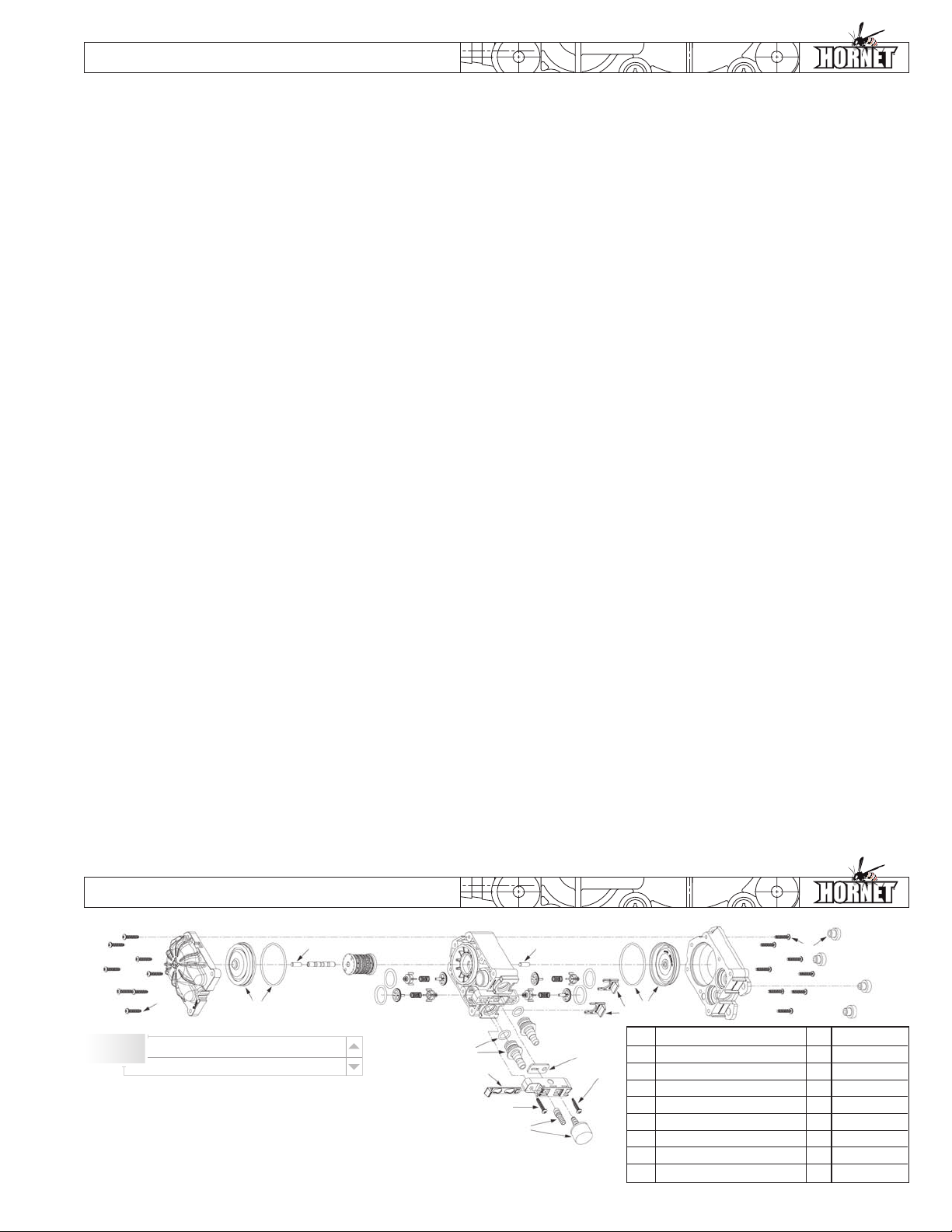
REPLACEMENT KITS
Interactive
Features
Click on the circled numbers to view close-up of part
Mouse-over Kits (below) to view line items
Item
Description
1
***Kit, Hardware, Hornet 1 85-6350-99
2
***Kit, Check Valve, Wilflex 1 85-9190-58
3
***Kit, Diaphragm, Wilflex 1 85-9545-58
4
***Kit, Fitting, 3/8” NPT 1 85-7779-99
4
***Kit, Fitting, 3/8” Barbed 1 85-7780-99
4
***Kit, Fitting, 1/2” Barbed 1 85-7782-99
5
***Kit, Retaining Clips 1 85-7783-99
6
***Kit, Air Fitting, Assembly 1 85-2175-99
*** Item number and price are for individual kits, minimum order quantity is 12.
Qty.
Item Number
Page 4
TROUBLESHOOTING
Pump will not run or runs slowly.
E ns ur e ai r p re s su re is a t l eas t 0 .3 ba r ( 5 p si g) ab ov e s t ar t 1.
up pressure and differential pressure (the difference
between air inlet and liquid discharge pressures) is not
less than 0.7 bar (10 psig).
Check air inlet filter for debris. A 5μ (micron) air filter 2.
must be installed at the air inlet of the pump to prevent
air compressor particulate from entering and damaging
the air distribution system.
Check for air leakage (blow by) at the exhaust of the 3.
pump. This could indicate worn seals/bore in the air
valve.
Disassemble pump and check for obstructions in the 4.
air passage-ways or objects which would obstruct the
movement of internal parts.
Check for sticking check valves. If material being 5.
pumped is not compatible with pump elastomers,
swelling may occur. Also, as the check valves wear,
they become smaller and can become stuck in the
seats.
Diaphragms may have a pinhole allowing air to escape 6.
to the liquid side of the pump reducing performance.
Check for sticking check valves. If material being 3.
pumped is not compatible with pump elastomers,
swelling may occur. Also, as the check valve wear, they
become smaller and can become stuck in the seats.
Pump may be operating (cycling) too fast. In this 4.
situation, to prime the pump you must lower the air
inlet pressure to achieve maximum suction lift. Once
pump is primed the inlet air pressure can be raised to
meet system requirements.
Pump air valve freezes.
Check for excessive moisture in compressed air 1.
line. Either install a dryer or hot air generator at the
compressor. A coalescing filter may also be used to
remove the water from the compressed air line some
applications.
Air bubbles in pump discharge.
Check for ruptured diaphragm.1.
Check tightness of fasteners and integrity of o-ring 2.
and seals.
Ensure hosing connections are airtight.3.
Pump runs but little or no product flows.
Check for pump cavitation; slow pump speed down to 1.
Product comes out air exhaust.
Check for diaphragm rupture.1.
allow thick material to flow into liquid chambers.
Verify that vacuum required to lift liquid is not greater 2.
than the vapor pressure of the material being pumped
(cavitation).
WARRANTY
Each and every product manufactured by Wilden Pump & Engineering, LLC is built to meet the highest standards of quality.
Every pump is functionally tested to insure integrity of operation. Wilden Pump & Engineering, LLC warrants that pumps,
accessories and parts manufactured or supplied by it to be free from defects in material and workmanship for a period
of five (5) years from date of installation or six (6) years from date of manufacture, whichever comes first. Failure due to
normal wear, misapplication, or abuse is, of course, excluded from this warranty. Since the use of Wilden pumps and parts is
beyond our control, we cannot guarantee the suitability of any pump or part for a particular application and Wilden Pump &
Engineering, LLC shall not be liable for any consequential damage or expense arising from the use or misuse of its products
on any application. Responsibility is limited solely to replacement or repair of defective Wilden Pump & Engineering, LLC. All
decisions as to the cause of failure are the sole determination of Wilden Pump & Engineering, LLC. Prior approval must be
obtained from Wilden for return of any items for warranty consideration and must be accompanied by the appropriate MSDS
for the product(s) involved. A Return Goods Tag, obtained from an authorized Wilden distributor, must be included with the
items which must be shipped freight prepaid. The foregoing warranty is exclusive and in lieu of all other warranties expressed
or implied (whether written or oral) including all implied warranties of merchantability and fitness for any particular purpose.
No distributor or other person is authorized to assume any liability or obligation for Wilden Pump & Engineering, LLC other
than expressly provided herein.
WIL-11260-E-03
 Loading...