

Dover PSG Wilden GP Series, PSG Wilden GPS430, PSG Wilden GPS820, PSG Wilden GPS1520, PSG Wilden GPS420 Engineering, Operation & Maintenance
...Page 1
EOM
Engineering
Operation &
Maintenance
Natural Gas-Operated
CSA-Certied
38 mm (1-1/2”), 51 mm (2”)
and 76 mm (3”) Metal Pumps
Where Innovation Flows
wildenpump.com
Page 2
TABLE OF CONTENTS
SECTION 1 CAUTIONS—READ FIRST! ..............................................1
SECTION 2 WILDEN PUMP DESIGNATION SYSTEM .................................2
SECTION 3 HOW IT WORKS—PUMP & AIR DISTRIBUTION SYSTEM ................3
SECTION 4 DIMENSIONAL DRAWINGS .............................................4
SECTION 5 PERFORMANCE
CSA Performance Curves
GPS420/GPS430 Metal EZ-Install TPE-Fitted ..................................9
GPS420/GPS430 Metal Full-Stroke PTFE-Fitted ...............................9
GPS820/GPS830 Metal EZ-Install TPE-Fitted .................................10
GPS820/GPS830 Metal Full-Stroke PTFE-Fitted ..............................10
GPS1520/GPS1530 Metal EZ-Install TPE-Fitted ...............................11
GPS1520/GPS1530 Metal Full-Stroke PTFE-Fitted ............................11
Suction-Lift Curves .......................................................12
SECTION 6 SUGGESTED INSTALLATION, OPERATION & TROUBLESHOOTING .......15
SECTION 7 DISASSEMBLY / REASSEMBLY ........................................18
Air Valve/Center Section Disassembly .......................................21
Reassembly Hints & Tips ..................................................25
SECTION 8 EXPLODED VIEW & PARTS LISTING
GPS420/GPS430 Metal ....................................................26
GPS820/830 Aluminum ...................................................28
GPS820/830 Stainless Steel ................................................30
GPS1520 Aluminum ......................................................32
GPS1520/GPS1530 Stainless Steel ..........................................34
SECTION 9 REPAIR KITS ..........................................................36
Page 3
Section 1
CAUTIONS—READ FIRST!
CAUTION: Do not apply pressurized gas to the
exhaust port — pump will not function.
TEMPERATURE LIMITS:
Buna-N –12°C to 82°C 10°F to 180°F
Wil-Flex™ –40°C to 107°C –40°F to 225°F
PTFE
1
4°C to 104°C 40°F to 220°F
1
4°C to 149°C (40°F to 300°F) - 13 mm (1/2") and 25 mm (1") models only.
CAUTION: Canadian Standards Association
(CSA) configured pumps should not be used in
temperatures lower than 0°C (32°F) or higher than
52°C (125°F).
CAUTION: Maximum temperature limits are
based upon mechanical stress only. Certain
chemicals will significantly reduce maximum
safe operating temperatures. Consult Chemical
Resistance Guide for chemical compatibility and
temperature limits.
WARNING : Prevent static sparking — If static
sparking occurs, fire or explosion could result.
Pump, valves and containers must be grounded
to a proper grounding point when handling
flammable fluids and whenever discharge of
static electricity is a hazard. Pumps must be
electrically grounded using the grounding
conductor provided. Improper grounding can
cause improper and dangerous operation.
CAUTION: Do not exceed 6.9 bar (100 psig) air
supply pressure.
CAUTION: The process fluid and cleaning fluids
must be chemically compatible with all wetted
pump components. Consult Chemical Resistance
Guide.
CAUTION: Do not exceed 82°C (180°F) air inlet
temperature for Pro-Flo® SHIFT models.
CAUTION: Pumps should be thoroughly flushed
before installing into process lines.
CAUTION: Always wear safety glasses when
operating pump. If diaphragm rupture occurs,
material being pumped may be forced out air
exhaust.
CAUTION: Before any maintenance or repair is
attempted, the compressed air line to the pump
should be disconnected and all air pressure
allowed to bleed from pump. Disconnect all
intake, discharge and air lines. Drain the pump
by turning it upside down and allowing any fluid
to flow into a suitable container.
CAUTION: Ensure that the gas supply line is clear
of debris. Use an in-line air filter. A 5μ (micron)
filter is recommended.
NOTE: When installing PTFE diaphragms,
it is important to tighten the outer pistons
simultaneously (turning in opposite directions)
to ensure a tight fit. (See torque specifications in
Section 7.)
NOTE: Some PTFE-fitted pumps come standard
from the factory with expanded PTFE gaskets
installed in the diaphragm bead of the liquid
chamber. PTFE gaskets cannot be re-used.
NOTE: Before starting disassembly, mark a line
from each liquid chamber to its corresponding air
chamber. This line will assist in proper alignment
during reassembly.
CAUTION: All CSA-certified pump are fitted with
a single-point exhaust to route all exhaust gas
through the muffler exhaust port. The gas outlet
must be vented to a safe location in accordance
with local codes or, in the absence of local codes,
an industry or nationally recognized code having
jurisdiction over the specified installation.
CAUTION : Tighten all hardware prior to installation.
WI L-1710 0- E-02 1 WILDEN PUMP & ENGINEERING, LLC
Page 4
Section 2
WILDEN PUMP DESIGNATION SYSTEM
CSA-CERTIFIED
NATURAL GAS
ADVANCED™
FIT PUMPS
51 mm (2") Pump
Maximum Flow
Maximum Flow
Rates:
Rate:
38 mm (1-1/2”)
675 LPM (178 GPM)
460 lpm (122 gpm)
51 mm (2”)
645 lpm (171 gpm)
76 mm (3”)
933 lpm (246 gpm)
LEGEND
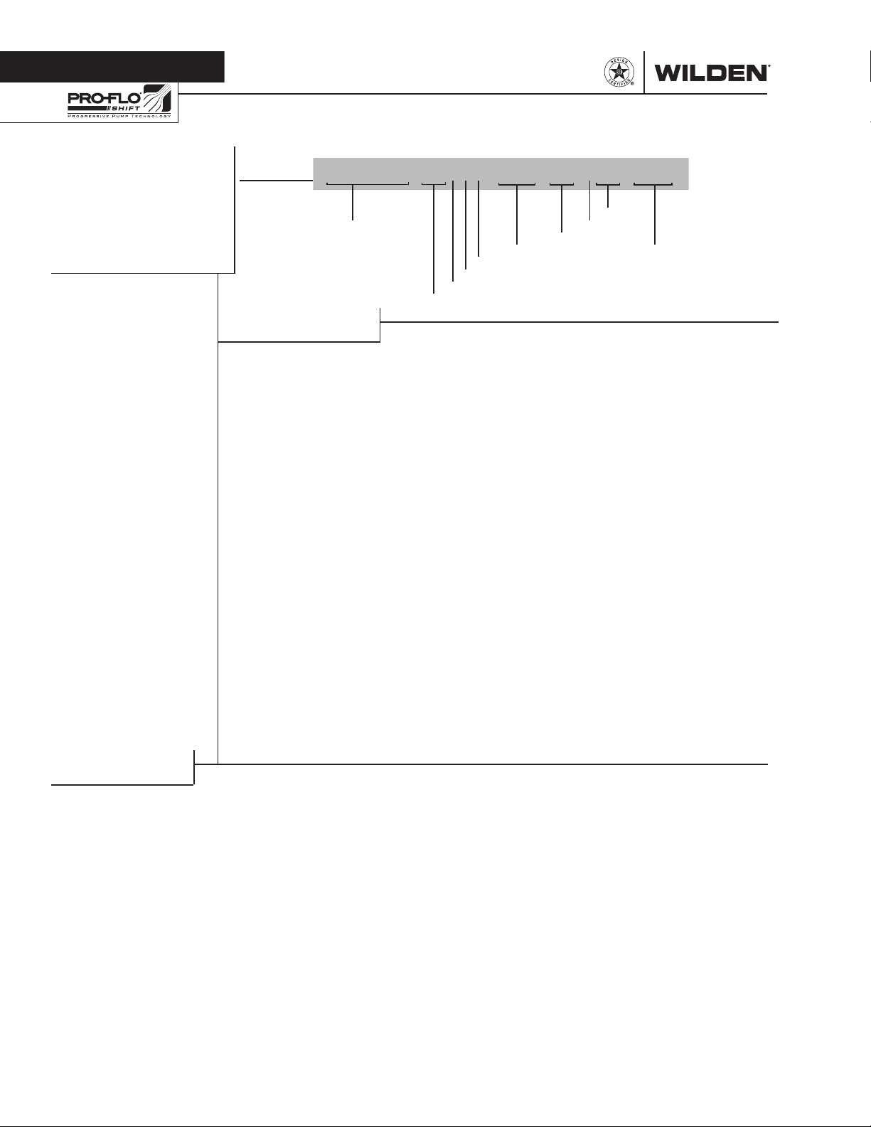
GPSXXXX/ XX XXX / XXX / XX/XXX / XXXX
MODEL VALVE SE AT
MATERIAL CODES
MODEL
GPS420 = ATE X, CSA, PRO-FLO
GPS430 = ATE X, CSA, PRO-FLO
GPS82 0 = ATE X, CSA, PRO-FLO
GPS83 0 = ATE X, CSA, PRO-FLO
GPS15 20 = ATE X, CSA, PRO-FLO
GPS15 30 = ATE X, CSA, PRO-FLO
SHIF T, THRE ADED
PORTS
SHIF T, FLANGED
PORTS
SHIF T, THRE ADED
PORTS
SHIF T, FLANGED
PORTS
SHIF T, THRE ADED
PORTS
SHIF T, FLANGED
PORTS
DIAPHRAGMS
AIR VALVE
CENTER BLOCK
AIR CHAMBERS
WETTED PARTS & OUTER PISTON
WETTED PARTS / OUTER PISTON /
AIR CHAMBER
AAA = ALUMINUM / ALUMINUM
/ ALUMINUM
SSS = STAINLESS STEEL /
STAINLESS STEEL /
STAINLESS STEEL
CENTER BLOCK
A = ALUMINUM
S = STAINLESS STEEL
AIR VALVE
A = ALUMINUM
S = STAINLESS STEEL
DIAPHRAGMS
TWS = FULL-STROKE PTFE
w/WIL-FLEX™ BACK-UP
ZWS = WIL-FLEX™, EZ-INSTALL
(Orange Dot)
O-RINGS
VALVE BALLS
VALVE BALL
TF = PTFE ( White)
WF = WIL-F LEX™ [Santoprene®
VALVE SE AT
A = ALUMINUM
S = STAINLESS STEEL
WF = WIL-F LEX™ [Santoprene®
VALVE SEAT O-RING
TF = PTFE
SPECIALT Y
CODE
(if applicable)
(Orange Dot)]
(Orange Dot)]
SPECIALTY CODES
0014 BSPT
0504
DIN Flange
NOTE: Most elastomer materials use colored dots for identification.
NOTE: Not all models are available wi th all material options.
WILDEN PUMP & ENGINEERING, LLC 2 WI L-17 10 0 - E-02
Page 5
Section 1
HOW IT WORKS—PUMP
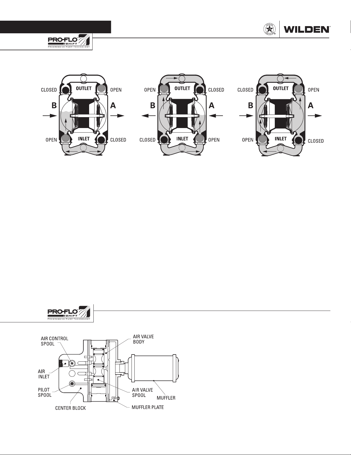
The Wilden diaphragm pump is an air-operated, positive displacement, self-priming pump. These drawings show flow pattern
through the pump upon its initial stroke. It is assumed the pump has no fluid in it prior to its initial stroke.
FIGUR E 1 The air valve dire cts pres surized
air to the back side of diaphragm A. The
compressed air is applied directly to the
liquid column separated by elastomeric
diaphragms. The diaphragm acts as
a separation membrane between the
compressed air and liquid; a balanced
load removes mechanical stress from the
diaphragm. The compressed air moves
the diaphragm away from the center of
the pump. The opposite diaphragm is
pulled in by the shaft connec ted to the
pressurized diaphragm. Diaphragm B
is on its suction stroke; air behind the
diaphragm has been forced out to the
atmosphere through the exhaust port of
the pump. The movement of diaphragm
B toward the center of the pump creates
a vacuum within chamber B. Atm ospheric
pressure forces fluid into the inlet
manifold forcing the inlet valve ball off its
seat. Liquid is free to move past the inlet
valve ball and fill the liquid chamber (see
shaded area).
HOW IT WORKS—AIR DISTRIBUTION SYSTEM
FIGURE 2 When the pressurized
diaphragm, diaphragm A, reaches the limit
of its discharge stroke, the air valve redirects
pressurized air to the back side of diaphragm
B. The pressurized air forces diaphragm
B away from the center while pulling
diaphragm A to the center. Diaphragm B is
now on its discharge stroke. Diaphragm B
forc es the inlet valve b all onto its se at due to
the hydraulic forces developed in the liquid
chamber and manifold of the pump. These
same hydraulic forces lift the discharge
valve ball off its seat, while the opposite
discharge valve ball is forced onto its seat,
forcing fluid to flow through the pump
discharge. The movement of diaphragm A
toward the center of the pump creates a
vacuum within liquid chamber A. Atmospheric pressure forces fluid into the inlet
manifold of the pump. The inlet valve ball
is forced off its seat allowing the fluid
being pumped to fill the liquid chamber.
FIGURE 3 At completion of the stroke,
the air valve again redirec ts air to the
back side of diaphragm A, which star ts
diaphragm B on its exhaust stroke. As
the pump reaches its original star ting
point, each diaphragm has gone through
one exhaust and one discharge stroke.
This constitutes one complete pumping
cycle. The pump may take several cycles
to completely prime depending on the
conditions of the application.
The heart of the patented Pro-Flo® SHIFT Air Distribution
System (ADS) is the air valve assembly. The air valve design
incorporates an unbalanced spool with the small end of the
spool being pressurized continuously while the large end of
the spool is alternately pressurized, then exhausted to move
the spool. The air valve spool directs pressurized air to one
chamber while exhausting the other. The air forces the main
shaft/diaphragm assembly to move to one side – discharging
liquid on that side and pulling liquid in on the other side. When
the shaft reaches the end of the stroke, the inner piston actuates
the pilot spool, which controls the air to the large end of the air
valve spool. The repositioning of the air valve spool routes the
air to the other air chamber. The air control spool allows air to
flow freely into the air chamber for the majority of each pump
stroke, but it significantly restricts the flow of air into the air
chamber when activated by the inner piston near the end of the
each stroke.
WI L-17 10 0 - E-02 3 WILDEN PUMP & ENGINEERING, LLC
Page 6
Section 4
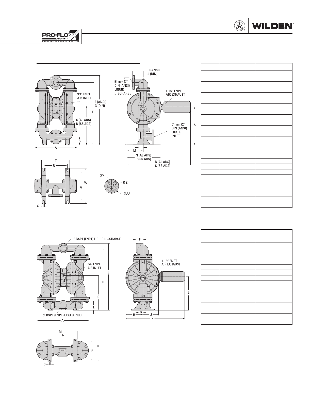
DIMENSIONAL DRAWINGS
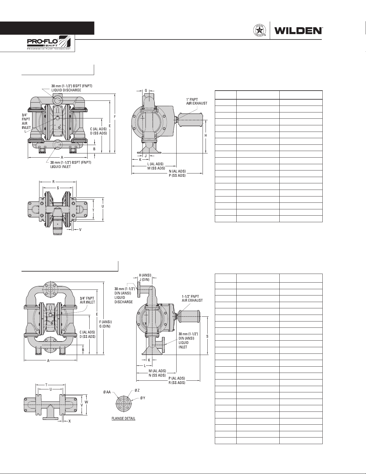
GPS420 Metal
DIMENSIONS
ITEM METRIC (mm) STANDARD (inch)
A 442 17.4
B 64 2.5
C 261 10.3
D 266 10.5
E 391 15.4
F 445 17.5
G 51 2.0
H 249 9.8
J 49 1.9
K 132 5.2
L 333 13.1
M 321 12.6
N 531 20.9
P 518 20.4
R 274 10.8
S 224 8.8
T 152 6.0
U 178 7.0
V 11 0.4
LW0231 REV. C
GPS430 Aluminum
DIMENSIONS
ITEM METRIC (mm) STANDARD (inch)
A 442 17.4
B 80 3.1
C 324 12.7
D 330 13.0
E 531 20.9
F 594 23.4
G 606 23.9
H 122 4.8
J 122 4.8
K 50 2.0
L 132 5.2
M 334 13.1
N 321 12.7
P 531 20.9
R 519 20.4
S 312 12.3
T 247 9.7
U 206 8.1
V 152 6.0
W 170 6.7
X 11 0.4
DIN (mm) ANSI (inch)
X 150 DIA. 5.0 DIA.
Y 109 DIA. 4.3 DIA.
Z 16 DIA. 0.6 DIA.
LW0296 REV. A
WILDEN PUMP & ENGINEERING, LLC 4 WI L-17 10 0 - E-02
Page 7
DIMENSIONAL DRAWINGS
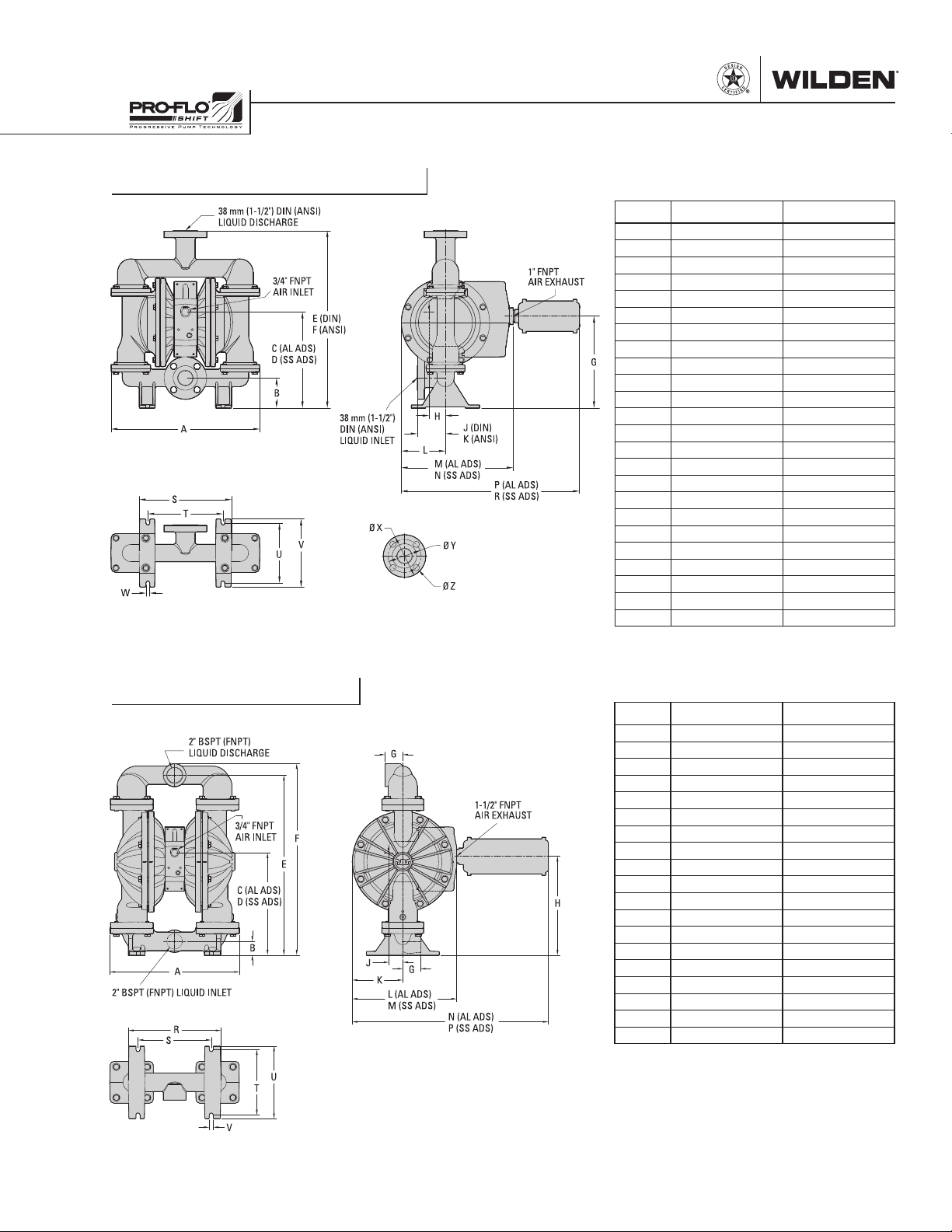
GPS430 Stainless Steel
DIMENSIONS
ITEM METRIC (mm) STANDARD (inch)
A 443 17.5
B 89 3.5
C 285 11.2
D 291 11.5
E 529 20.8
F 528 20.8
G 273 10.8
H 49 1.9
J 86 3.4
K 84 3.3
L 132 5.2
M 333 13.1
N 321 12.6
P 531 20.9
R 518 20.4
S 274 10.8
T 224 8.8
U 178 7.0
V 203 8.0
W 11 0.4
DIN (mm) ANSI (inch)
X 150 DIA. 5.0 DIA.
Y 109 DIA. 4.3 DIA.
Z 16 DIA. 0.6 DIA.
LW0233 REV. B
GPS820 Aluminum
DIMENSIONS
ITEM METRIC (mm) STANDARD (inch)
A 453 17.9
B 48 1.9
C 358 14.1
D 364 14.3
E 630 24.8
F 670 26.4
G 62 2.4
H 346 13.6
J 48 1.9
K 177 7.0
L 366 14.4
M 354 13.9
N 687 27.1
P 675 26.6
R 324 12.8
S 257 10.1
T 229 9.0
U 254 10.0
V 14 0.6
LW0238 REV. A
WI L-17 10 0 - E-02 5 WILDEN PUMP & ENGINEERING, LLC
Page 8
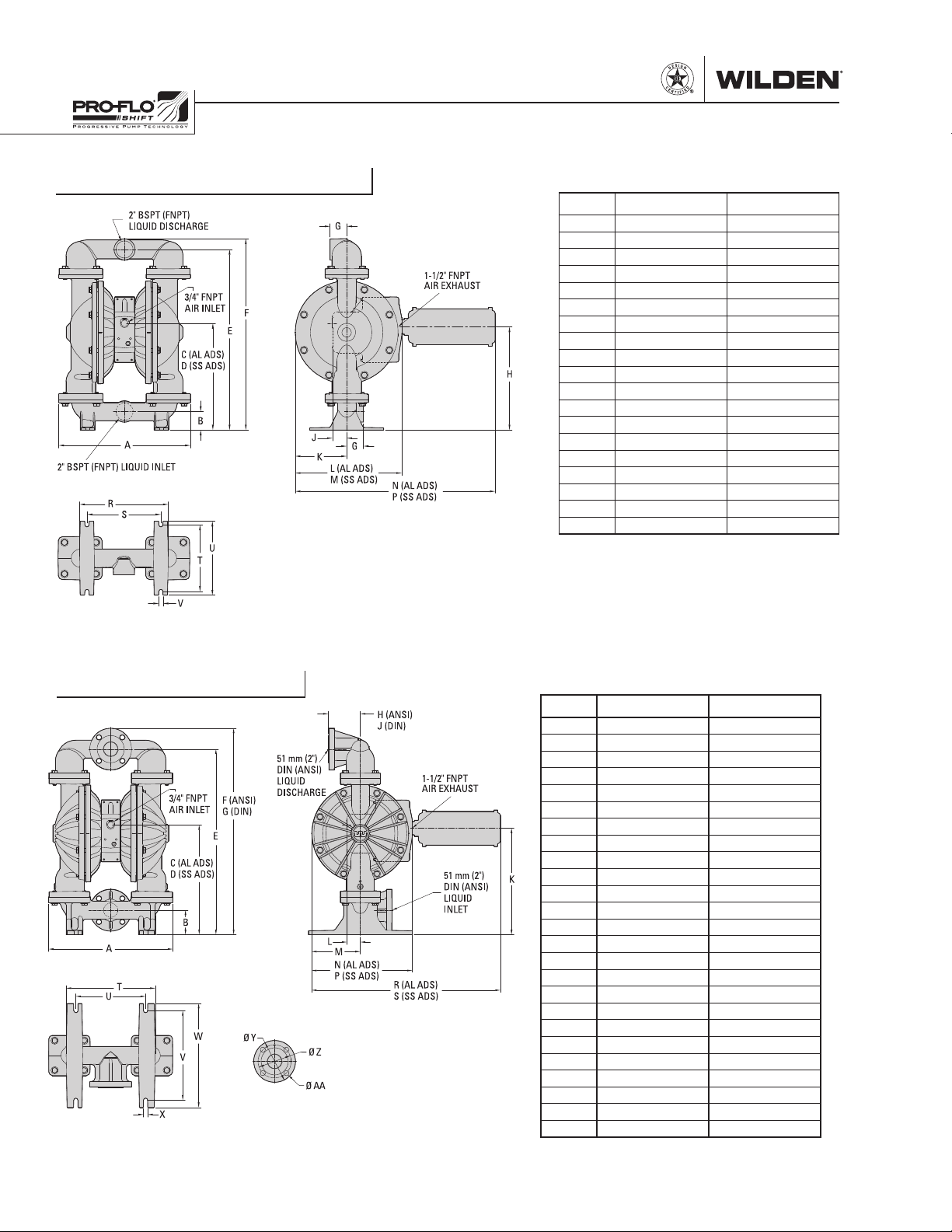
GPS820 Stainless Steel
DIMENSIONS
ITEM METRIC (mm) STANDARD (inch)
A 452 17.8
B 64 2.5
C 367 14.3
D 372 14.7
E 620 24.4
F 658 25.9
G 58 2.3
H 354 14.0
J 48 1.9
K 178 7.0
L 366 14.4
M 353 13.9
N 687 27.0
P 674 26.5
R 305 12.0
S 254 10.0
T 229 9.0
U 254 10.0
V 15 0.6
LW0240 REV. A
GPS830 Aluminum
DIMENSIONS
ITEM METRIC (mm) STANDARD (inch)
A 452 17.8
B 89 3.5
C 400 15.7
D 405 16.0
E 675 26.6
F 752 29.6
G 758 29.8
H 116 4.6
J 117 4.6
K 387 15.3
L 48 1.9
M 177 7.0
N 366 14.4
P 354 13.9
R 687 27.1
S 675 26.6
T 324 12.8
U 254 10.0
V 326 12.8
W 378 14.9
X 16 0.6
DIN (mm) ANSI (inch)
Y 165 DIA. 6.0 DIA.
Z 125 DIA. 4.8 DIA.
AA 18 DIA. 0.8 DIA.
LW0239 REV. A
WILDEN PUMP & ENGINEERING, LLC 6 WI L-17 10 0 - E-02
Page 9
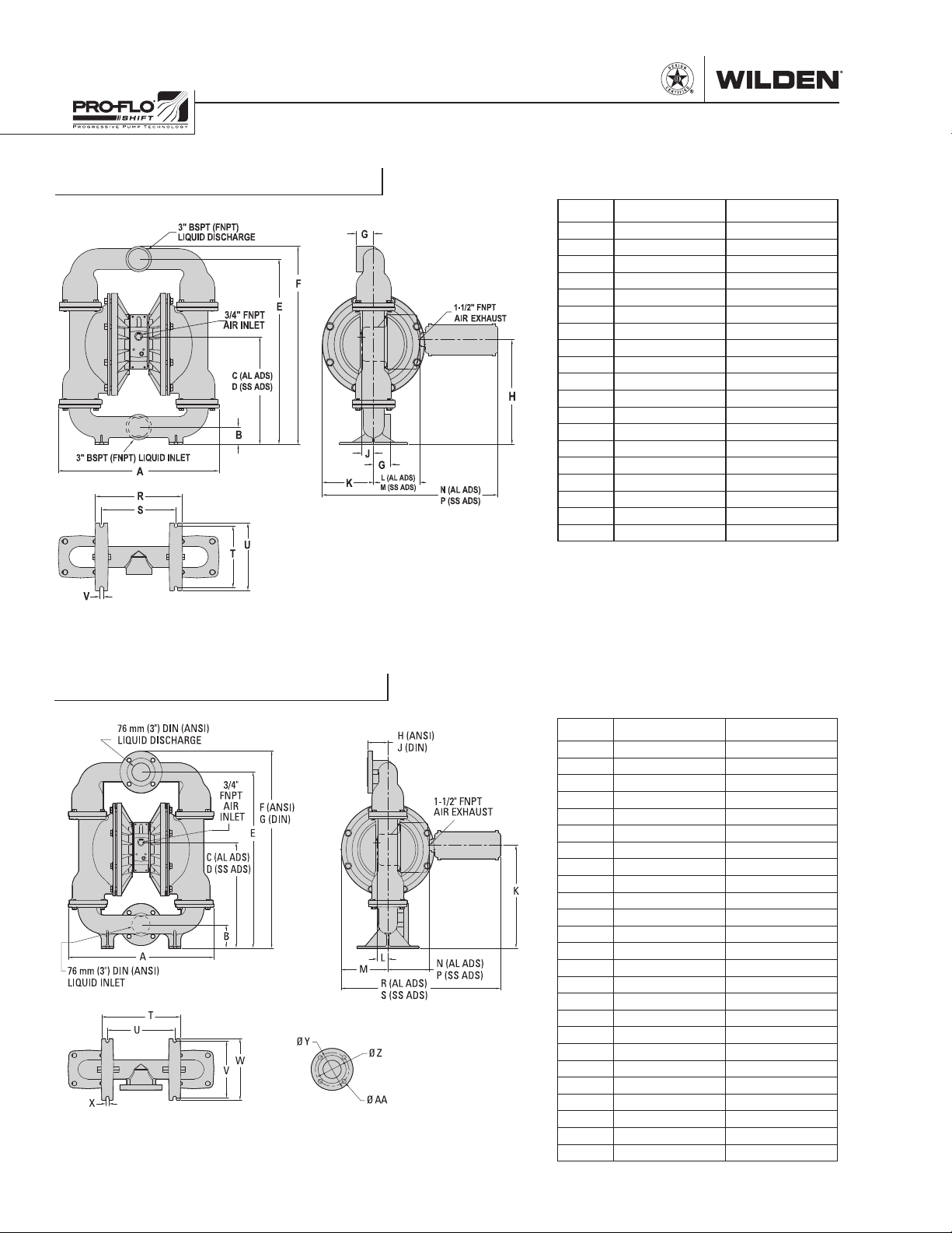
DIMENSIONAL DRAWINGS
GPS830 Stainless Steel
DIMENSIONS
ITEM METRIC (mm) STANDARD (inch)
A 452 17.8
B 89 3.5
C 424 16.7
D 429 16.9
E 678 26.7
F 754 29.7
G 760 29.9
H 116 4.6
J 115 4.5
K 412 16.2
L 48 1.9
M 177 7.0
N 366 14.2
P 354 13.9
R 677 27.1
S 675 26.6
T 304 12.0
U 254 10.0
V 325 12.8
W 379 14.9
X 14 0.6
DIN (mm) ANSI (inch)
Y 165 DIA. 6.0 DIA.
Z 125 DIA. 4.8 DIA.
AA 18 DIA. 0.8 DIA.
LW0241 REV. A
GPS1520 Aluminum
DIMENSIONS
ITEM METRIC (mm) STANDARD (inch)
A 635 25.0
B 61 2.4
C 426 16.8
D 759 29.9
E 818 32.2
F 84 3.3
G 50 2.0
H 210 8.3
J 189 7.4
K 722 28.4
L 414 16.3
M 358 14.1
N 307 12.1
P 257 10.1
R 282 11.1
S 15 0.6
LW0319 REV. A
WI L-17 10 0 - E-02 7 WILDEN PUMP & ENGINEERING, LLC
Page 10
DIMENSIONAL DRAWINGS
GPS1520 Stainless Steel
DIMENSIONS
ITEM METRIC (mm) STANDARD (inch)
A 650 25.6
B 71 2.8
C 443 17.5
D 449 17.7
E 765 30.1
F 815 32.1
G 71 2.8
H 431 17.0
J 48 1.9
K 211 8.3
L 189 7.4
M 177 7.0
N 721 28.4
P 709 27.9
R 356 14.0
S 305 12.0
T 257 10.1
U 279 11.0
V 15 0.6
LW0259 REV. B
GPS1530 Stainless Steel
DIMENSIONS
ITEM METRIC (mm) STANDARD (inch)
A 659 26.0
B 105 4.1
C 477 18.8
D 483 19.0
E 796 31.3
F 890 35.1
G 891 35.3
H 90 3.6
J 88 3.5
K 465 18.3
L 48 1.9
M 211 8.3
N 189 7.4
P 177 7.0
R 721 28.4
S 709 27.9
T 356 14.0
U 305 12.0
V 256 10.1
W 279 11.0
X 14 0.6
DIN (mm) ANSI (inch)
Y 200 DIA. 7.5 DIA.
Z 160 DIA. 6.0 DIA.
AA 18 DIA. 0.8 DIA.
WILDEN PUMP & ENGINEERING, LLC 8 WI L-17 10 0 - E-02
LW0260 REV. A
Page 11
Section 5
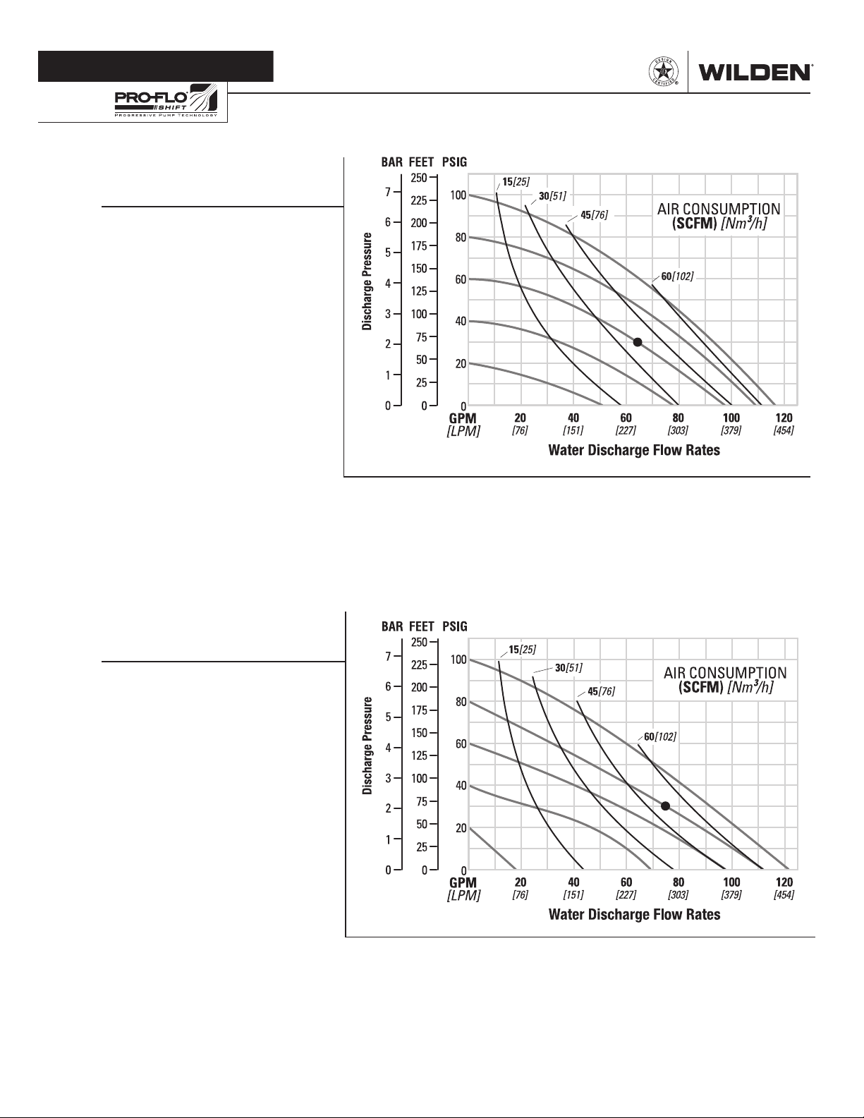
PERFORMANCE
GPS420/GPS430 METAL
EZ-INSTALL TPE-FITTED
Ship Weight ........
430 Flanged AL 28 kg (62 lb)
420 Threaded SS 50 kg (111 lb)
430 Flanged SS 53 kg (116 lb)
Air Inlet ........................................19 mm (3/4”)
Inlet ...........................................38 mm (1-1/2”)
Outlet ........................................38 mm (1-1/2”)
Suction Lift ............................ 4.7 m Dry (15.3’)
9.0 m Wet (29.5’)
Disp. per Stroke1 ...................... 0.8 L (0.22 gal)
Max. Flow Rate ..................441 lpm (117 gpm)
Max. Size Solids .........................6.4 mm (1/4”)
1
Displacement per stroke was calculated at
4.8 bar (70 psig) air inlet pressure against a
2.1 bar (30 psig) head pressure.
Example: To pump 242 lpm (64 gpm)
against a discharge head of 2.1 bar
(30 psig) requires 4.1 bar (60 psig) and
63 Nm3/h (37 scfm) air consumption.
Caution: Do not exceed 6.9 bar (100 psig) air
supply pressure.
420 Threaded AL 26 kg (57 lb)
Flow rates indicated on chart were determined by pumping water.
For optimum life and performance, pumps should be specified so that daily operation
parameters will fall in the center of the pump's performance curve.
GPS420/GPS430 METAL
FULL-STROKE PTFE-FITTED
Ship Weight ........
430 Flanged AL 28 kg (62 lb)
420 Threaded SS 50 kg (111 lb)
430 Flanged SS 53 kg (116 lb)
Air Inlet ........................................19 mm (3/4”)
Inlet ...........................................38 mm (1-1/2”)
Outlet ........................................38 mm (1-1/2”)
Suction Lift ............................ 4.5 m Dry (14.8’)
8.6 m Wet (28.4’)
Disp. per Stroke1 ...................... 0.9 L (0.24 gal)
Max. Flow Rate ................. 460 lpm (122 gpm)
Max. Size Solids .........................6.4 mm (1/4”)
1
Displacement per stroke was calculated at
4.8 bar (70 psig) air inlet pressure against a
2.1 bar (30 psig) head pressure.
Example: To pump 280 lpm (74 gpm)
against a discharge head of 2.1 bar
(30 psig) requires 5.5 bar (80 psig) and
88 Nm3/h (52 scfm) air consumption
Caution: Do not exceed 6.9 bar (100 psig) air
supply pressure.
WI L-17 10 0 - E-02 9 WILDEN PUMP & ENGINEERING, LLC
420 Threaded AL 26 kg (57 lb)
Flow rates indicated on chart were determined by pumping water.
For optimum life and performance, pumps should be specified so that daily operation
parameters will fall in the center of the pump's performance curve.
Page 12
PERFORMANCE
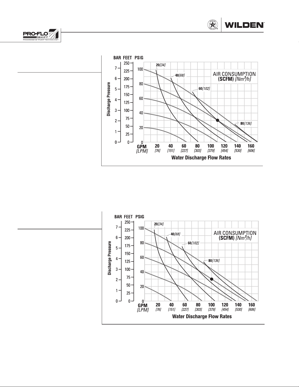
GPS820/GPS830 METAL
EZ-INSTALL TPE-FITTED
Ship Weight ...
Air Inlet ................................... 19 mm (3/4”)
Inlet ............................................ 51 mm (2”)
Outlet .........................................51 mm (2”)
Suction Lift ....................... 5.5 m Dry (18.2’)
9.0 m Wet (29.5’)
Disp. per Stroke
Max. Flow Rate ............ 645 lpm (171 gpm)
Max. Size Solids ....................6.4 mm (1/4”)
1
Displacement per stroke was calculated at
4.8 bar (70 psig) air inlet pressure against a
2.1 bar (30 psig) head pressure.
Example: To pump 416 lpm (110 gpm)
against a discharge head of 2.1 bar
(30 psig) requires 5.5 bar (80 psig) and
102 Nm
Caution: Do not exceed 6.9 bar (100 psig)
air supply pressure.
820 Threaded AL 47 kg (104 lb)
830 Flanged AL 54 kg (118 lb)
820 Threaded SS 73 kg (161 lb)
830 Flanged SS 81 kg (178 lb)
1
..................2.1 L (0.55 gal)
3
/h (60 scfm) air consumption.
Flow rates indicated on chart were determined by pumping water.
For optimum life and performance, pumps should be specified so that daily operation
parameters will fall in the center of the pump's performance curve.
GPS820/GPS830 METAL
FULL-STROKE PTFE-FITTED
Ship Weight ...
Air Inlet ................................... 19 mm (3/4”)
Inlet ............................................ 51 mm (2”)
Outlet .........................................51 mm (2”)
Suction Lift ....................... 6.1 m Dry (20.0’)
9.0 m Wet (29.5’)
Disp. per Stroke
Max. Flow Rate ............ 636 lpm (168 gpm)
Max. Size Solids ....................6.4 mm (1/4”)
1
Displacement per stroke was calculated at
4.8 bar (70 psig) air inlet pressure against a
2.1 bar (30 psig) head pressure.
Example: To pump 379 lpm (100 gpm)
against a discharge head of 2.1 bar
(30 psig) requires 5.5 bar (80 psig) and
112 Nm
Caution: Do not exceed 6.9 bar (100 psig)
air supply pressure.
820 Threaded AL 47 kg (104 lb)
830 Flanged AL 54 kg (118 lb)
820 Threaded SS 73 kg (161 lb)
830 Flanged SS 81 kg (178 lb)
1
..................2.4 L (0.63 gal)
3
/h (66 scfm) air consumption.
Flow rates indicated on chart were determined by pumping water.
For optimum life and performance, pumps should be specified so that daily operation
parameters will fall in the center of the pump's performance curve.
WILDEN PUMP & ENGINEERING, LLC 10 WI L-17 10 0 - E-02
Page 13
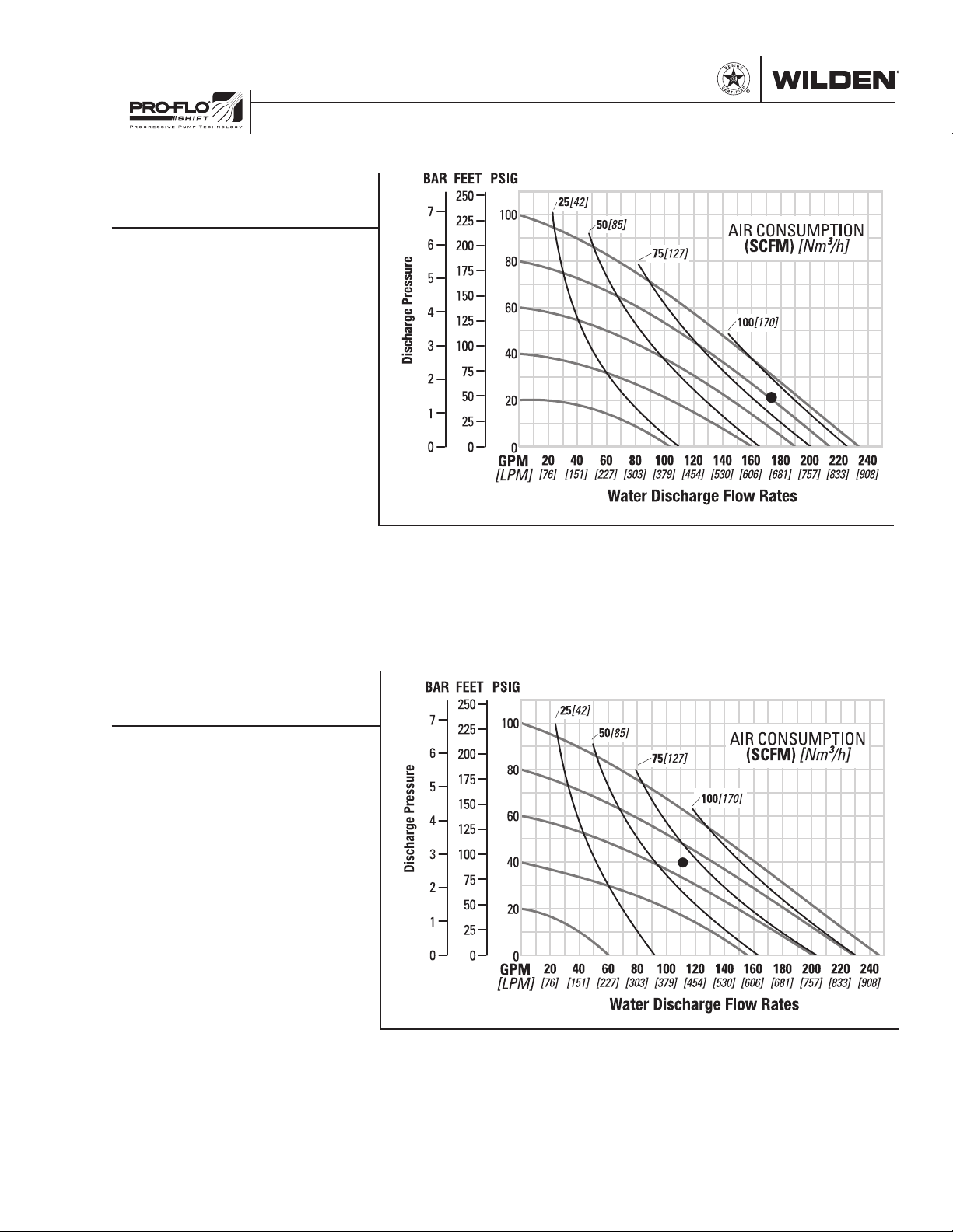
PERFORMANCE
GPS1520/GPS1530 METAL
EZ-INSTALL TPE-FITTED
Ship Weight .....
1520 Threaded SS 126 kg (278 lb)
1530 Flanged SS 136 kg (300 lb)
Air Inlet ................................... 19 mm (3/4”)
Inlet ............................................ 76 mm (3”)
Outlet ......................................... 76 mm (3”)
Suction Lift ....................... 4.7 m Dry (15.3’)
9.0 m Wet (29.5’)
Disp. per Stroke
Max. Flow Rate ............ 884 lpm (234 gpm)
Max. Size Solids ..................12.7 mm (1/2”)
1
Displacement per stroke was calculated at
4.8 bar (70 psig) air inlet pressure against a
2.1 bar (30 psig) head pressure.
Example: To pump 659 lpm (174 gpm)
against a discharge head of 1.4 bar (20
psig) requires 5.5 bar (80 psig) and
143 Nm
Caution: Do not exceed 6.9 bar (100 psig)
air supply pressure.
1520 Threaded AL 69 kg (152 lb)
1
.................. 4.2 L (1.11 gal)
3
/h (84 scfm) air consumption.
Flow rates indicated on chart were determined by pumping water.
For optimum life and performance, pumps should be specified so that daily operation
parameters will fall in the center of the pump's performance curve.
GPS1520/GPS1530 METAL
FULL-STROKE PTFE-FITTED
Ship Weight .....
1520 Threaded SS 126 kg (278 lb)
1530 Flanged SS 136 kg (300 lb)
Air Inlet ................................... 19 mm (3/4”)
Inlet ............................................ 76 mm (3”)
Outlet ......................................... 76 mm (3”)
Suction Lift ....................... 5.9 m Dry (19.3’)
8.6 m Wet (28.4’)
Disp. per Stroke
Max. Flow Rate ............ 993 lpm (246 gpm)
Max. Size Solids ..................12.7 mm (1/2”)
1
Displacement per stroke was calculated at
4.8 bar (70 psig) air inlet pressure against a
2.1 bar (30 psig) head pressure.
Example: To pump 420 lpm (111 gpm)
against a discharge head of 2.8 bar
(40 psig) requires 4.8 bar (70 psig) and
110 Nm
Caution: Do not exceed 6.9 bar (100 psig)
air supply pressure.
WI L-17 10 0 - E-02 11 WILDEN PUMP & ENGINEERING, LLC
1520 Threaded AL 69 kg (152 lb)
1
.................. 5.0 L (1.32 gal)
3
/h (65 scfm) air consumption.
Flow rates indicated on chart were determined by pumping water.
For optimum life and performance, pumps should be specified so that daily operation
parameters will fall in the center of the pump's performance curve.
Page 14
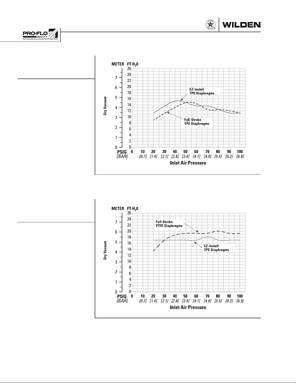
SUCTION-LIFT CURVES
GPS420/GPS430
METAL SUCTION-LIFT
CAPABILITY
GPS820/GPS830
METAL SUCTION-LIFT
CAPABILITY
Suction lift curves are calibrated for pumps operating
at 305 m (1,000') above sea level. This chart is meant
to be a guide only. There are many variables which
can affect your pump’s operating characteristics. The
number of intake and discharge elbows, viscosity of
pumping fluid, elevation (atmospheric pressure) and
pipe friction loss all affect the amount of suction lift
your pump will attain.
WILDEN PUMP & ENGINEERING, LLC 12 WI L-17 10 0 - E-02
Page 15
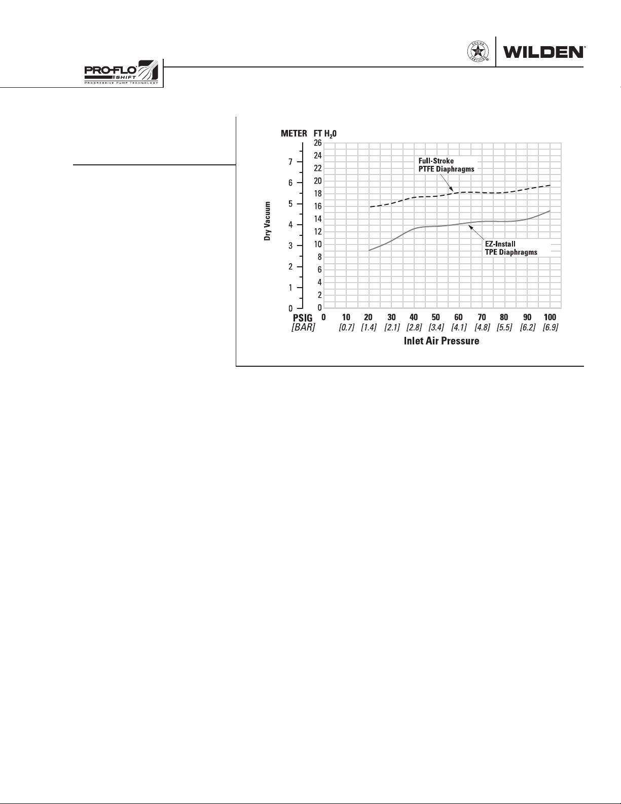
SUCTION-LIFT CURVES
GPS1520/GPS1530
METAL SUCTION-LIFT
CAPABILITY
Suction lift curves are calibrated
for pumps operating at 305 m
(1,000') above sea level. This
chart is meant to be a guide
only. There are many variables
which can affect your pump’s
operating characteristics. The
number of intake and discharge
elbows, viscosity of pumping
fluid, elevation (atmospheric
pressure) and pipe friction loss
all affect the amount of suction
lift your pump will attain.
Full-Stroke
PTFE Diaphragms
EZ-Install
TPE Diaphragms
WI L-17 10 0 - E-02 13 WILDEN PUMP & ENGINEERING, LLC
Page 16
NOTES
WILDEN PUMP & ENGINEERING, LLC 14 WI L-17 10 0 - E-02
Page 17
Section 6
CSA-CERTIFIED PUMP SUGGESTED INSTALLATION
Prior to pump installation, ensure that the flow and
suction lift requirements are within the pump model’s
capabilities. Refer to the Section 5, Performance of the
Engineering, Operation and Maintenance (EOM) Manual
for specific flow and suction-lift capabilities.
Before installation confirm that the pump materials of
construction are compatible with pumping application.
Refer to the Wilden Chemical Resistance Guide for
assistance with wetted path and elastomer options.
PIPING: The pump should be located so that the length
and complexity of the suction and discharge piping is
minimized. Unnecessary elbows, bends and fittings can
increase friction losses and should be avoided.
Pipe sizes should be selected to keep friction losses
within practical limits. The suction pipe diameter should
be equivalent or larger than the diameter of the suction
inlet on your Wilden pump. The suction hose must be noncollapsible, reinforced type as these pumps are capable of
pulling a high vacuum. Discharge piping should also be
the equivalent or larger than the diameter of the pump
discharge to help reduce friction losses.
All piping should be supported independently of the
pump. In addition, the piping should be correctly aligned
with the inlet and discharge connection of the pump to
avoid placing stress on the pump fittings. Flexible hose
can be installed to aid in absorbing the forces created by
the natural reciprocating action of the pump and will also
assist in minimizing pump vibration.
GAS SUPPLY: The pump should have a supply line large
enough (a 3/4” supply line is recommended for 1-1/2” and
larger pumps) to supply the volume of air necessary to
achieve the desired pumping rate. Gas pressure to the
pump should be controlled by a pressure-regulating valve
and should not exceed a maximum of 6.9 bar (100 psig).
It is suggested that a needle valve be placed in the supply
line to control the flow of gas to the pump. For best results,
a 5μ (micron) filter should be installed before the gas inlet
of the pump to eliminate the majority of compressed gas
line contaminants.
TYPE OF GAS: Sweet gas is highly recommended for
natural gas-powered pumps. Please consult the factory if
considering using sour gas as levels of hydrogen sulfide
(H2S) may cause unacceptable corrosion and chemical
attack.
PUMP MOUNTING AND INSTALLATION: For simple
installation and removal of the pump shut-off valves
should be installed in the inlet and discharge plumbing.
If the pump is to be mounted in a fixed location, a mounting
pad placed between the pump and the foundation will
assist in minimizing pump vibration. If quick-closing
valves are installed at any point in the discharge system,
or if pulsation within a system becomes a problem, a
surge suppressor (SD Equalizer®) should be installed to
protect the pump, piping and gauges from surges and
water hammer.
SOLIDS PASSAGE: All Wilden pumps are capable of
passing solids. A strainer should be used at the inlet of the
pump to ensure that the pump’s rated solids capabilities
are not exceeded. Refer to the Section 5 of this EOM
manual for specific solids-passage capabilities.
FLOODED SUCTION: Pumps in service with a positive
suction head are most efficient when the inlet pressure is
limited to 0.5–0.7 bar (7–10 psig). Premature diaphragm
failure may occur if positive suction is 0.7 bar (10 psig)
or higher.
SUCTION LIFT: When used in self-priming applications, it
is critical that all fittings and connections are airtight or a
reduction or loss of pump suction capability will result.
GAS OUTLET: All CSA-certified pumps are fitted with the
single point exhaust option so that all exhaust gases are
routed through the muffler plate exhaust port. The gas
outlet must be recaptured or vented to a safe location
in accordance with locally, nationally and/or industry
recognized codes. The standard Wilden muffler supplied
with CSA-certified pumps will reduce sound levels below
OSHA specifications but may not comply with regulatory
codes for recapturing or venting exhaust gases.
GROUNDING: Pumps and accessories must be electrically
grounded to a proper grounding point to prevent an
accumulation of electro-static charge when used in
potentially explosive areas. CSA-certified pumps come
with a grounding strap and are fitted with a grounding
screw for the purpose of electrically grounding the
pump. Periodic inspection of the ground connection
should be performed to ensure the equipment is properly
grounded. Refer to the Wilden CE Safety Supplement
and Safety Manual for additional ATEX-certified pump
considerations.
FUNCTIONAL TESTING:
1. Tighten all hardware prior to initial start-up. Refer to
Section 7, Reassembly Hints & Tips in the EOM manual
for torque specifications.
2. Prior to pump installation connect compressed gas line
[do not exceed rated pressure of 6.9 bar (100 psig)] to
inlet of pump to ensure that pump cycles consistently.
3. Cycle pump for 2-3 minutes.
4. After pump installation, check piping connections for
leaks.
PUMP OPERATION:
1. To avoid damage to the pump new installations should
be checked for any debris in tank or piping system.
2. Once installation is complete, pump operation can be
started. Confirm the shut-off valves in the inlet and
discharge plumbing are open. Opening the gas shutoff valve [do not exceed the pump’s maximum rated
pressure of 6.9 bar (100 psig)]. The pressure regulating
valve and needle valve can be used to adjust the speed
of the pump.
3. Retighten all exposed fasteners after two (2) hours of
operation. Refer to Section 7, Reassembly Hints & Tips
in the EOM manual for torque specifications.
WI L-17 10 0 - E-02 15 WILDEN PUMP & ENGINEERING, LLC
Page 18
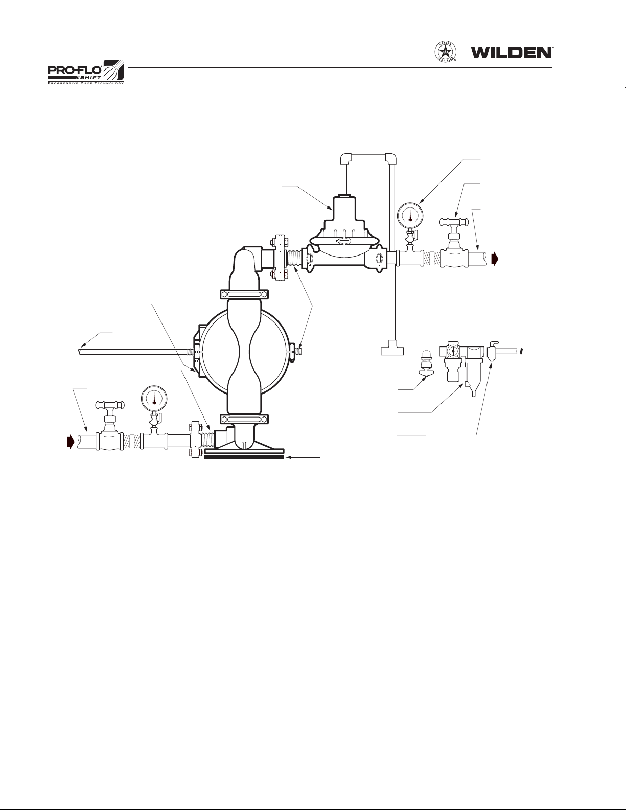
CSA-CERTIFIED PUMP SUGGESTED INSTALLATION
FOOTPAD
DISCHARGE
This illustration is a generic
representation of an air-operated
double-diaphragm pump.
EQUALIZER
SURGE DAMPENER
(OPTIONAL)
GAUGE
®
(OPTIONAL)
SHUT-OFF
VALVE
GROUNDING
LOCATION
OUTLET GAS
FLEXIBLE
CONNECTION
SUCTION
EMERGENCY SHUT DOWN PROCEDURE: In the case of
an emergency situation, the pump should be stopped
immediately. To stop the pump’s operation close the gas
shut–off valve (user-supplied). A properly functioning
valve will cut-off the gas supply, stopping the pump. The
shut-off valve should be located far enough away from
the pumping equipment such that it can be reached safely
in an emergency situation.
In the event of pump or diaphragm failure, close shut-off
valves at the inlet and discharge of pump to eliminate the
possibility of medium leakage
In the event of a power failure, the gas shut-off valve
should be closed, if restarting of the pump is not desirable
once power is regained.
FLEXIBLE
CONNECTION
NEEDLE VALVE
COMBINATION
FILTER & REGULATOR
AIR SHUT-OFF VALVE
Refer to the Wilden CE Safety Supplement, Safety Manual
and EOM Manual for additional information.
PRIOR TO MAINTENANCE: Before any maintenance is
performed, confirm pump is completely de-energized by
shutting off the pump and disconnecting the gas supply
line to the pump.
Refer to Section 7, Reassembly Hints & Tips and Section
8, Exploded View & Parts Listings in the EOM manual for
maintenance and spare parts information.
WILDEN PUMP & ENGINEERING, LLC 16 WI L-17 10 0 - E-02
Page 19
CSA-CERTIFIED PUMP SUGGESTED OPERATION & MAINTENANCE
OPERATION: CSA-certified pumps are pre-lubricated,
and do not require in-line lubrication. Additional
lubrication will not damage the pump, however if the
pump is heavily lubricated by an external source, the
pump’s internal lubrication may be washed away. If
the pump is then moved to a non-lubricated location,
it may need to be disassembled and re-lubricated as
described in the DISASSEMBLY/REASSEMBLY.
Pump discharge rate can be controlled by limiting
the volume and/or pressure of the air supply to the
pump. An air regulator is used to regulate air pressure.
A needle valve is used to regulate volume. Pump
discharge rate can also be controlled by throttling
the pump discharge by partially closing a valve in
the discharge line of the pump. This action increases
friction loss which reduces flow rate. (See Section 5.)
This is useful when the need exists to control the pump
from a remote location. When the pump discharge
pressure equals or exceeds the air supply pressure,
the pump will stop; no bypass or pressure relief valve
is needed, and pump damage will not occur. The
pump has reached a “deadhead” situation and can be
TROUBLESHOOTING
restarted by reducing the fluid discharge pressure or
increasing the air inlet pressure. CSA-certified pumps
run solely on pressurized gas and do not generate
heat, therefore your process fluid temperature will not
be affected.
MAINTENANCE AND INSPECTIONS: Since each
application is unique, maintenance schedules may
be different for every pump. Frequency of use, line
pressure, viscosity and abrasiveness of process fluid
all affect the parts life of a Wilden pump. Periodic
inspections have been found to offer the best
means for preventing unscheduled pump downtime.
Personnel familiar with the pump’s construction and
service should be informed of any abnormalities that
are detected during operation.
RECORDS: When service is required, a record should
be made of all necessary repairs and replacements.
Over a period of time, such records can become a
valuable tool for predicting and preventing future
maintenance problems and unscheduled downtime. In
addition, accurate records make it possible to identif y
pumps that are poorly suited to their applications.
Pump will not run or runs slowly.
1. Ensure that the air inlet pressure is at least 0.4 bar
(5 psig) above startup pressure and that the differential
pressure (the difference between air inlet and liquid
discharge pressures) is not less than 0.7 bar (10 psig).
2. Check air inlet filter for debris (see SUGGESTED
INSTALLATION).
3. Check for extreme air leakage (blow by) which
would indicate worn seals/bores in the air valve,
pilot spool and main shaft.
4. Disassemble pump and check for obstructions
in the air passageways or objects which would
obstruct the movement of internal parts.
5. Check for sticking ball check valves. If material being
pumped is not compatible with pump elastomers,
swelling may occur. Replace ball check valves and
seals with proper elastomers. Also, as the check
valve balls wear out, they become smaller and can
become stuck in the seats. In this case, replace balls
and seats.
6. Check for broken inner pistons which will cause the
air valve spool to be unable to shift.
7. Remove plug from pilot spool exhaust.
Pump runs, but little or no product flows.
1. Check for pump cavitation; slow pump speed down
to allow thick material to flow into liquid chambers.
2. Verify that vacuum required to lift liquid is not
WI L-17 10 0 - E-02 17 WILDEN PUMP & ENGINEERING, LLC
greater than the vapor pressure of the material
being pumped (cavitation).
3. Check for sticking ball check valves. If material being
pumped is not compatible with pump elastomers,
swelling may occur. Replace ball check valves and
seats with proper elastomers. Also, as the check
valve balls wear out, they become smaller and can
become stuck in the seats. In this case, replace balls
and seats.
Pump air valve freezes.
1. Check for excessive moisture in compressed
air. Either install a dryer or hot air generator for
compressed air. Alternatively, a coalescing filter
may be used to remove the water from the
compressed air in some applications.
Air bubbles in pump discharge.
1. Check for ruptured diaphragm.
2. Check tightness of outer pistons (refer to Section 7).
3. Check tightness of fasteners and integrity of O-rings
and seals, especially at intake manifold.
4. Ensure pipe connections are airtight.
Product comes out air exhaust.
1. Check for diaphragm rupture.
2. Check tightness of outer pistons to shaft.
Page 20
Section 7
PUMP DISASSEMBLY PUMP DISASSEMBLY
Tools Required:
• Appropriate-sized
Wrench
• Adjustable Wrench
• Vise equipped w/
soft jaws (such as
plywood, plastic
or other suitable
material)
CAUTION: Before any maintenance or repair is attempted, the compressed air line
to the pump should be disconnected and all air pressure allowed to bleed from the
pump. Disconnect all intake, discharge and air lines. Drain the pump by turning it
upside down and allowing any fluid to flow into a suitable container. Be aware of
any hazardous effects of contact with your process fluid.
NOTE: The model photographed is an aluminum 51 mm (2”) Advanced FIT pump.
Your specific pump model may vary from configuration shown; however, pump
disassembly procedure will be the same.
Step 1
Before starting disassembly, mark
a line from each liquid chamber to
its corresponding air chamber. This
line will assist in proper alignment
during reassembly.
WILDEN PUMP & ENGINEERING, LLC 18 WI L-17 10 0 - E-02
Step 2
Using the appropriate-sized wrench
for your pump size, loosen the
discharge manifold from the liquid
chambers.
Step 3
Lift the discharge manifold to
expose discharge valve balls and
valve seats. Inspect ball cage area
of manifold for excessive wear or
damage.
Page 21

PUMP DISASSEMBLY
Step 4
Remove the discharge valve balls
and valve seats from the liquid
chambers and inspect for nicks,
gouges, chemical attack or abrasive
wear. Replace worn parts with
genuine Wilden parts for reliable
performance.
Step 5
Using the appropriate-sized wrench,
loosen the inlet manifold from the
liquid chambers. NOTE: Inverting
the pump will facilitate removal of
inlet manifold.
Step 6
Remove the inlet manifold to expose
the valve balls and valve seats.
Step 7
Remove the inlet valve balls and
valve seats from the inlet manifold
and liquid chambers and inspect for
nicks, gouges, chemical attack or
abrasive wear.
NOTE: Replace worn parts with
genuine Wilden parts for reliable
performance.
WI L-17 10 0 - E-02 19 WILDEN PUMP & ENGINEERING, LLC
Step 8
Using the appropriate-sized wrench,
remove the liquid chamber from the
center section.
Step 9
The liquid chamber should be
removed to expose the diaphragm
and outer piston using an adjustable
wrench. Remove the diaphragm
assembly from the center section.
Repeat for opposite side.
Page 22

PUMP DISASSEMBLY AIR VALVE / CENTER SECTION DISASSEMBLY
Step 10
Inspect the diaphragm assembly for
wear, damage or chemical attack.
Replace any damaged components
with genuine Wilden parts for
reliable performance.
Step 11
To remove diaphragm assembly
from shaft, secure shaft with
soft jaws (aluminum, plastic or
plywood) to ensure the shaft is
not damaged. Using an adjustable
wrench, remove the diaphragm
assembly from the shaft
Step 12
Remove outer piston and stud if
equipped. Inspect for wear and
replace if necessary.
GROUNDING STRAP FOR CSA PUMPS
Figure 1 Figure 2
Canadian Standards Association (CSA) configured pumps must be
Step 13
To remove diaphragm assembly
from shaf t, secure shaft with sof t
jaws (aluminum, plastic, or plywood)
to ensure the shaft is not damaged.
Using an adjustable wrench, remove
the diaphragm assembly from the
shaft.
WILDEN PUMP & ENGINEERING, LLC 20 WI L-17 10 0 - E-02
electrically grounded using the grounding strap provided (Figure 1).
Improper grounding can cause improper and dangerous operation. To
properly attach the grounding strap to a CSA pump, identify the designated
grounding location on the muffler plate; using the provided self-tapping
screw and grounding wire, thread the grounding screw through the
grounding wire lug, into the muffler plate and tighten securely (Figure 2).
Completion of the pump grounding procedure must be done in accordance
with local codes, or in the absence of local codes, an industrial or nationally
recognized code having jurisdiction over the specified installation.
Page 23

AIR VALVE / CENTER SECTION DISASSEMBLY
Tools Required:
• Appropriate-sized
Wrenches
• Snap-Ring Pliers
• O-Ring Pick
CAUTION: Before any maintenance or repair is attempted, the compressed air line
to the pump should be disconnected and all air pressure allowed to bleed from the
pump. Disconnect all intake, discharge and air lines. Drain the pump by turning it
upside down and allowing any fluid to flow into a suitable container. Be aware of
hazardous effects of contact with your process fluid.
®
The Wilden Pro-Flo
SHIFT metal pumps utilize a revolutionary Pro-Flo® SHIFT air
distribution system. Proprietary composite seals reduce the co efficient of friction
and allow the Pro-Flo® SHIFT to run lube-free. The Pro-Flo® SHIFT air distribution
system is designed to perform in on/off, non-freezing, non-stalling, tough duty
applications.
Step 1
Using a pair of snap-ring pliers,
remove the snap ring from pilot
sleeve.
Step 2
Using an O-ring pick, remove O-ring
from modulator spool.
Step 3
Using the appropriate-sized wrench,
loosen and remove the fasteners
that attach the air chamber to center
section.
WI L-17 10 0 - E-02 21 WILDEN PUMP & ENGINEERING, LLC
Page 24

AIR VALVE / CENTER SECTION DISASSEMBLY
Step 4
Lift away air chamber from center
section and remove center block
gasket. Replace gasket if necessary.
Step 5
Turn assembly over and remove the
pilot spool sleeve from the center
section.
Step 6
Using an O-ring pick, gently remove
the O-ring from the opposite side of
the dimpled end of the pilot spool.
Step 7
Gently remove the pilot spool from
the sleeve and inspect for nicks,
wear or damage. Replace the pilot
spool assembly or sleeve O-rings
if necessary. During reassembly,
never insert the dimpled end of the
pilot spool first, this will damage the
single urethane O-ring by passing it
over the ports in the pilot sleeve.
NOTE: Seals should not be removed
from the assembly. Seals are not
sold separately.
WILDEN PUMP & ENGINEERING, LLC 22 WI L-17 10 0 - E-02
Step 8
Remove modulator spool from
center section. Check for wear to
spool or O-rings and replace if
necessary.
Step 9
Using the appropriate-sized wrench,
loosen the fasteners and lift away
remaining air chamber and center
block gasket from center section.
Replace gasket if necessary.
Page 25

AIR VALVE / CENTER SECTION DISASSEMBLY
Step 10
Using an O-ring pick, remove
the two (2) shaft bushings from
center block. Inspect and replace
if necessary. Using an O-ring pick,
gently remove the two (2) Glyd™
rings from the center block. Inspect
and replace if necessary.
Step 11
Using an O-ring pick, remove the
two (2) Glyd™ rings from modulator
spool bore. Inspect and replace if
necessary.
Step 12
Using an appropriate-sized wrench,
remove the pilot exhaust muffler.
Inspect for damage or contamination
and replace if necessary.
Step 13
Using an appropriate-sized hex
wrench, loosen and remove the
four (4) air valve bolts from center
section assembly.
WI L-17 10 0 - E-02 23 WILDEN PUMP & ENGINEERING, LLC
Step 14
Lift away muffler plate and muffler plate gasket from center block. Inspect
for wear and replace if necessary. Lift away the air valve assembly and
remove air valve gasket. Inspect the gasket and replace if necessary.
Page 26

AIR VALVE / CENTER SECTION DISASSEMBLY
Step 15
Remove air valve end cap to expose
air valve spool by lifting up on end
cap. Inspect O-ring on end cap using
an O-ring pick. Replace O-ring(s)
if necessary. NOTE: The Pro-Flo
SHIFT air valve incorporates an end
cap at both ends of the air valve.
®
Step 16
Remove the air valve spool from the air valve body by threading one air
valve bolt into the end of the air valve spool and gently sliding the spool out
of the air valve body. Inspect seals for signs of wear and replace the entire
air valve assembly if necessary. Re-insert the spool immediately into air
valve body after inspection as the seals expand and cannot be reinserted
after a length of time.
NOTE: Seals should not be removed from the assembly. Seals are not sold
separately.
WILDEN PUMP & ENGINEERING, LLC 24 WI L-17 10 0 - E-02
Page 27
REASSEMBLY HINTS & TIPS
AS SE M B LY:
Upon performing applicable maintenance to the air
distrib ution system, t he pump can now be re assembled.
Please refer to the disassembly instructions for photos
and parts placement. To reassemble the pump, follow
the disassembly instructions in reverse order. The air
distribution system needs to be assembled first, then
the diaphragms and finally the wetted path. Please
find the applicable torque specifications on this page.
The following tips will assist in the assembly process.
• Lubricate air valve bore, center section shaft
and pilot spool bore with NLGI grade 2 white EP
bearing grease or equivalent.
• Clean the inside of the center section shaft bore to ensure
no damage is done to new shaft seals.
• A small amount of NLGI grade 2 white EP bearing grease
can be applied to the muffler and air valve gaskets to
lubricate gaskets during assembly.
• Make sure that the exhaust port on the muffler plate is
centered between the two exhaust ports on the center
section.
• Stainless bolts should be lubed to reduce the possibility
of seizing during tightening.
• Use a mallet to tamp lightly on the large clamp bands to
seat the diaphragm before tightening.
GPS420/430 MAXIMUM TORQUE SPECIFCATIONS
Description of Part Torque
Air Valve (Aluminum, Stainless Steel) 13.6 N•m (120 in-lb)
Air Chamber/Center Block 27.1 N•m (20 ft-lb)
Outer Pistons 54.2 N•m (40 ft-lb)
Liquid Chamber to Air Chamber 47.5 N•m (35 ft-lb)
Manifolds to Liquid Chamber 47.5 N•m (35 ft-lb)
GPS820/830 MAXIMUM TORQUE SPECIFCATIONS
Description of Part Torque
Air Valve (Aluminum, Stainless Steel) 13.6 N•m (120 in-lb)
Air Chamber/Center Block 27.1 N•m (20 ft-lb)
Manifold to Liquid Chamber 75.6 N•m (55 ft-lb)
Liquid Chamber to Air Chamber 75.6 N•m (55 ft-lb)
Outer Pistons with Aluminum Inner Pistons 109 N•m (80 ft-lb)
Outer Pistons with Stainless Steel Inner Pistons 119 N•m (88 ft-lb)
GPS1520/1530 MAXIMUM TORQUE SPECIFCATIONS
Description of Part Torque
Air Valve (Aluminum, Stainless Steel) 13.6 N•m (120 in-lb)
Air Chamber/Center Block 27.1 N•m (20 ft-lb)
Inner Piston Ring 19.0 N•m (14 ft-lb)
Outer Piston 136 N•m (100 ft-lb)
Liquid Chamber to Air Chamber 149 N•m (110 ft-lb)
Manifolds to Air Chamber 149 N•m (110 ft-lb)
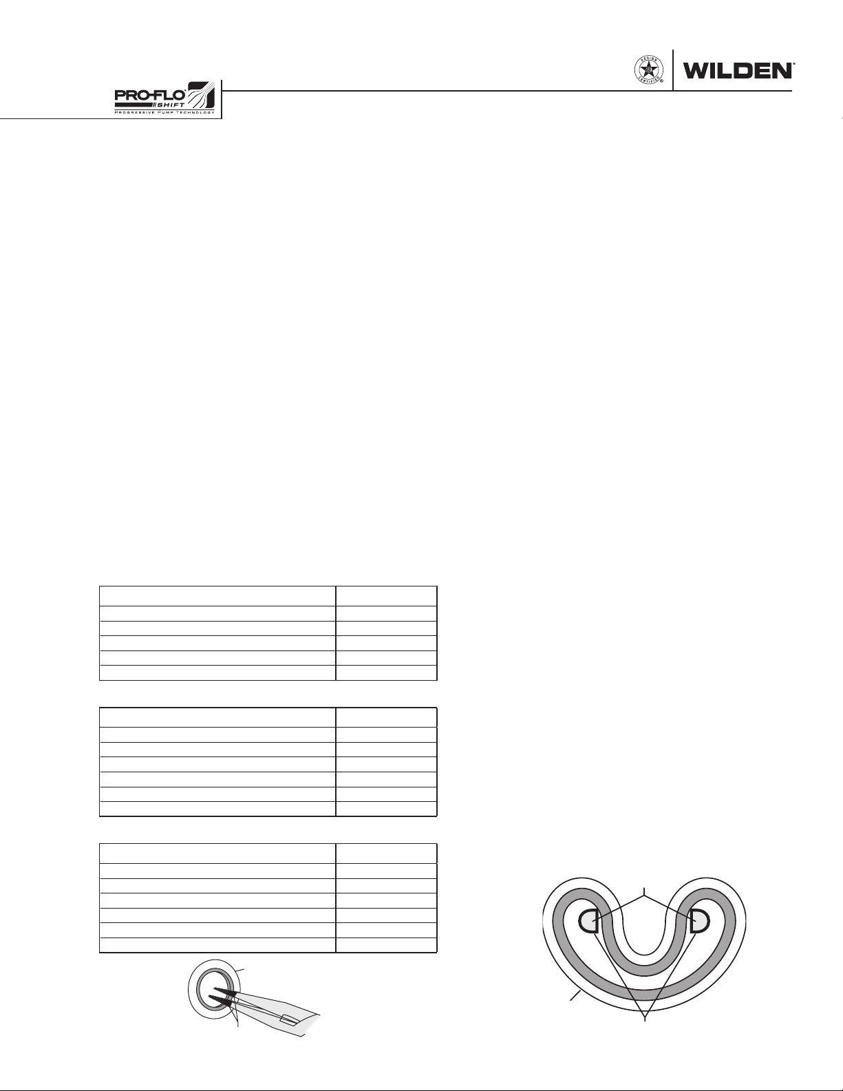
Figure A
SHA FT SE AL
SHAFT SEAL INSTALLATION:
PRE-INSTALLATION
• Once all of the old seals have been removed, the
inside of the bushing should be cleaned to ensure
no debris is left that may cause premature damage
to the new seals.
INSTALLATION
The following tools can be used to aid in the installation
of the new seals:
Needle-Nose Pliers
Phillips Screwdriver
Electrical Tape
• Wrap electrical tape around each leg of the needle-nose
pliers (heat shrink tubing may also be used). This is done
to prevent damaging the inside surface of the new seal.
• With a new seal in hand, place the two legs of the
needle-nose pliers inside the seal ring. (See Figure A.)
• Open the pliers as wide as the seal diameter will allow,
then with two fingers pull down on the top portion of
the seal to form a kidney shape. (See Figure B.)
• Lightly clamp the pliers together to hold the seal into
the kidney shape. Be sure to pull the seal into as tight
of a kidney shape as possible, this will allow the seal to
travel down the bushing bore easier.
• With the seal clamped in the pliers, insert the seal into
the bushing bore and position the bottom of the seal
into the correct groove. Once the bottom of the seal is
seated in the groove, release the clamp pressure on the
pliers. This will allow the seal to partially snap back to its
original shape.
• After the pliers are removed, you will notice a slight
bump in the seal shape. Before the seal can be properly
resized, the bump in the seal should be removed as
much as possible. This can be done with either the
Phillips screwdriver or your finger. With either the side
of the screwdriver or your finger, apply light pressure
to the peak of the bump. This pressure will cause the
bump to be almost completely eliminated.
• Lubricate the edge of the shaft with
white EP bearing grease.
• Slowly insert the center shaft with a rotating motion.
This will complete the resizing of the seal.
• Perform these steps for the remaining seals.
Figure B
NEEDLE-NOSE
PLIERS
NLGI grade 2
SHA FT SE AL
WI L-17 10 0 - E-02 25 WILDEN PUMP & ENGINEERING, LLC
TAPE
TAPE
Page 28
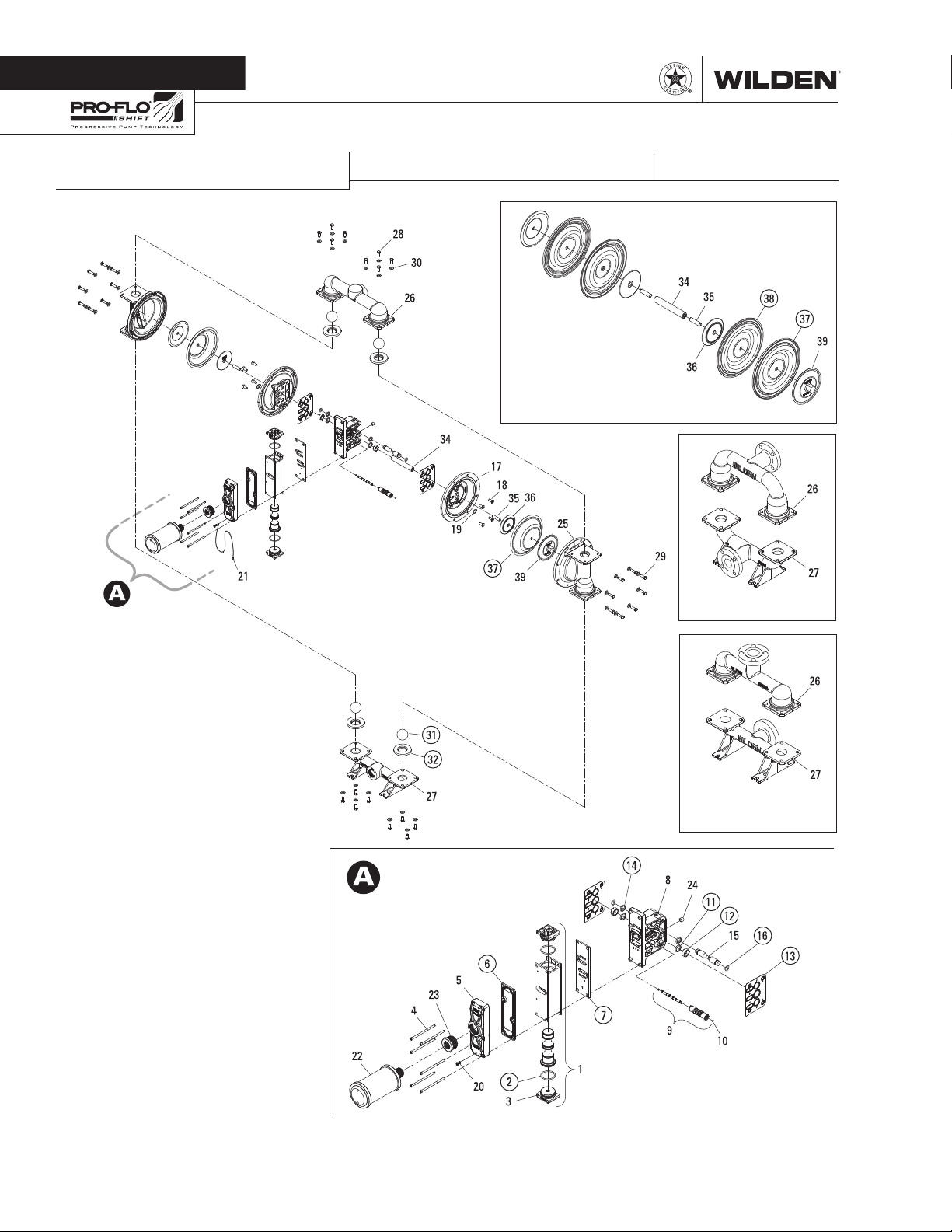
Section 8
EXPLODED VIEW & PARTS LISTING
GPS420/GPS430 METAL
EXPLODED VIEW
FULL-STROKE PTFE
ALUMINUM FLANGED
STAINLESS STEEL
FLANGED
METAL ADS
LWO299 Rev. E
ALL CIRCLED PART IDENTIFIERS ARE INCLUDED IN REPAIR KITS
WILDEN PUMP & ENGINEERING, LLC 26 WIL-1710 0 - E - 02
Page 29
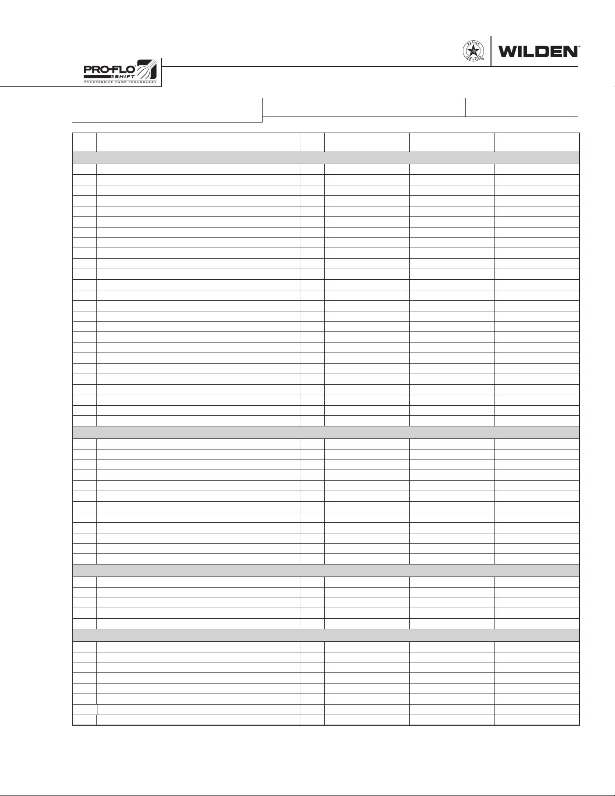
EXPLODED VIEW & PARTS LISTING
GPS420/GPS430 METAL
Item
Description Qty.
PARTS LISTING
GPS420/430/SSSAA/…/
P/N
GPS420/430/SSSSS/…/
P/N
GPS420/430/AAAAA/…/
P/N
AIR DISTRIBUTION COMPONENTS
1 Air Valve Assembly, Pro-Flo® SHIFT
2 O-Ring, End Cap (-225, Ø1.859" x Ø.139") 2 04-2390-52-700 04-2390-52-700 04-2390-52-700
3 End Cap 2 04-2340-01 04-2340-03 04-2340-01
4 Screw, SHC, Air Valve (1/4"-20 x 4 1/2") 4 N/A 01-6000-03 N/A
Screw, SHC, Air Valve (1/4"-20 x 4 1/2") 6 01-6000-03 N/A 01-6000-03
5 Muffler Plate, Pro-Flo
6 Gasket, Muffler Plate, Pro-Flo
7 Gasket, Air Valve, Pro-Flo
®
SHIFT 1 04-3189-01 04-3189-03 04-3189-01
®
8 Center Block Assembly, Pro-Flo
9 Pilot Sleeve Assembly 1 04-3880-99 04-3880-99 04-3880-99
10 Pilot Spool Retaining O-Ring (-009, Ø.208" x Ø.070") 2 04-2650-49-700 04-2650-49-700 04-2650-49-700
11 Seal, Shaft 2 08-3210-55-225 08-3210-55-225 08-3210-55-225
12 Bushing, Shaft 2 08-3306-13 08-3306-13 08-3306-13
13 Gasket, Center Block Pro-Flo
14 O-Ring, (-210, Ø.734" x Ø.139") 2 04-3209-49 04-3209-49 04-3209-49
15 Air Control Spool 1 04-3859-03 04-3859-03 04-3859-03
16 Air Control Spool Retaining O-Ring (-114, Ø.612" x Ø.103") 2 04-3879-50 04-3879-50 04-3879-50
17 Air Chamber, Pro-Flo V™ 2 04-3698-03 04-3698-03 04-3694-01
18 Screw, HSFHS (3/8"-16 x 1") 8 71-6250-08 71-6250-03 71-6250-08
19 Retaining Ring 2 04-3890-03 04-3890-03 04-3890-03
20 Grounding Screw, (10-32 x 1/2") Self Tapping 1 04-6345-08 04-6345-08 04-6345-08
21 Grounding Strap, CSA 1 01-8303-99 01-8303-99 01-8303-99
22 Muffler 1" MNPT 1 15-3510-99R 15-3513-99 15-3510-99R
23 Bushing Reducer 1-1/2" MNPT to 1" FNPT 1 04-6959-08 04-6959-03 04-6959-08
24 Plug, Pipe, 1/4" MNPT 1 00-7010-08 00-7010-03 00-7010-08
1
®
SHIFT 1 04-3509-52 04-3509-52 04-3509-52
SHIFT 1 04-2638-52 04-2638-52 04-2638-52
®
2
SHIFT
®
SHIFT 2 04-3529-56 04-3529-56 04-3529-56
1 04-2039-01 04-2039-03 04-2039-01
1 04-3129-01 04-3129-03 04-3129-01
WETTED PATH COMPONENTS
25 Liquid Chamber 2 04-5015-03 04-5015-03 04-5015-01
26 Manifold, Discharge, 1-1/2" (NPT) 1 04-5035-03 04-5035-03 04-5035-01
Manifold, Discharge, 1-1/2" (BSPT) 1 04-5036-03 04-5036-03 04-5036-01
Manifold, Discharge, 1-1/2" (ANSI) 1 04-5045-03 04-5045-03 04-5045-01
Manifold, Discharge, 1-1/2" (DIN) 1 04-5046-03 04-5046-03 04-5046-01
27 Manifold, Inlet, 1-1/2" (NPT) 1 04-5095-03 04-5095-03 04-5095-01
Manifold, Inlet, 1-1/2" (BSPT) 1 04-5096-03 04-5096-03 04-5096-01
Manifold, Inlet, 1-1/2" (ANSI) 1 04-5125-03 04-5125-03 04-5125-01
Manifold, Inlet, 1-1/2" (DIN) 1 04-5126-03 04-5126-03 04-5126-01
28 Screw, HHC (3/8"-16 x 1") 16 08-6130-03 08-6130-03 08-6130-08
29 Screw, HHC (3/8"-16 x 1-1/4") 16 04-6190-03 04-6190-03 04-6140-08
30 Washer, Flat, (Ø.406" x Ø.812" x .065") 32 04-6740-03 04-6740-03 15-6740-08-50
VALVE BALLS/VALVE SEATS/VALVE O-RINGS
31 Ball, Valve 4 08-1080-58-50 08-1080-58-50 08-1080-58-50
Ball, Valve, PTFE-Fitted 4 04-1085-55 04-1085-55 04-1085-55
32 Seat, Valve 4 04-1128-58 04-1128-58 04-1128-58
Seat, Valve, PTFE-Fitted 4 04-1129-03 04-1129-03 04-1129-01
33
Valve Seat O-Ring, PTFE-Fitted (-338, Ø3.100" x Ø.210") (not shown)
4 71-1281-55 71-1281-55 71-1281-55
TPE/PTFE COMPONENTS
34 Shaft, Stallion 1 04-3848-03 04-3848-03 04-3848-03
Shaft, PTFE-Fitted 1 04-3800-03-700 04-3800-03-700 04-3800-03-700
35 Shaft Stud
36 Piston, Inner 2 04-3700-01-700 04-3700-01-700 04-3700-01-700
37 Diaphragm, Primary 2 04-1022-58 04-1022-58 04-1022-58
Diaphragm, Primary, PTFE-Fitted 2 04-1040-55-42 04-1040-55-42 04-1040-55-42
38 Diaphragm, Back-Up, PTFE-Fitted 2 04-1065-57 04-1065-57 04-1065-57
39 Piston, Outer 2 04-4550-03 04-4550-03 04-4552-01
1
Air Valve Assembly includes items 2 and 3.
2
Metal Center Block Assembly includes items 11, 12 and 14.
All boldface items are primary wear parts.
WI L-17 10 0 - E-02 27 WILDEN PUMP & ENGINEERING, LLC
2 08-6150-08 08-6150-08 08-6150-08
LW0300 Rev. E
Page 30
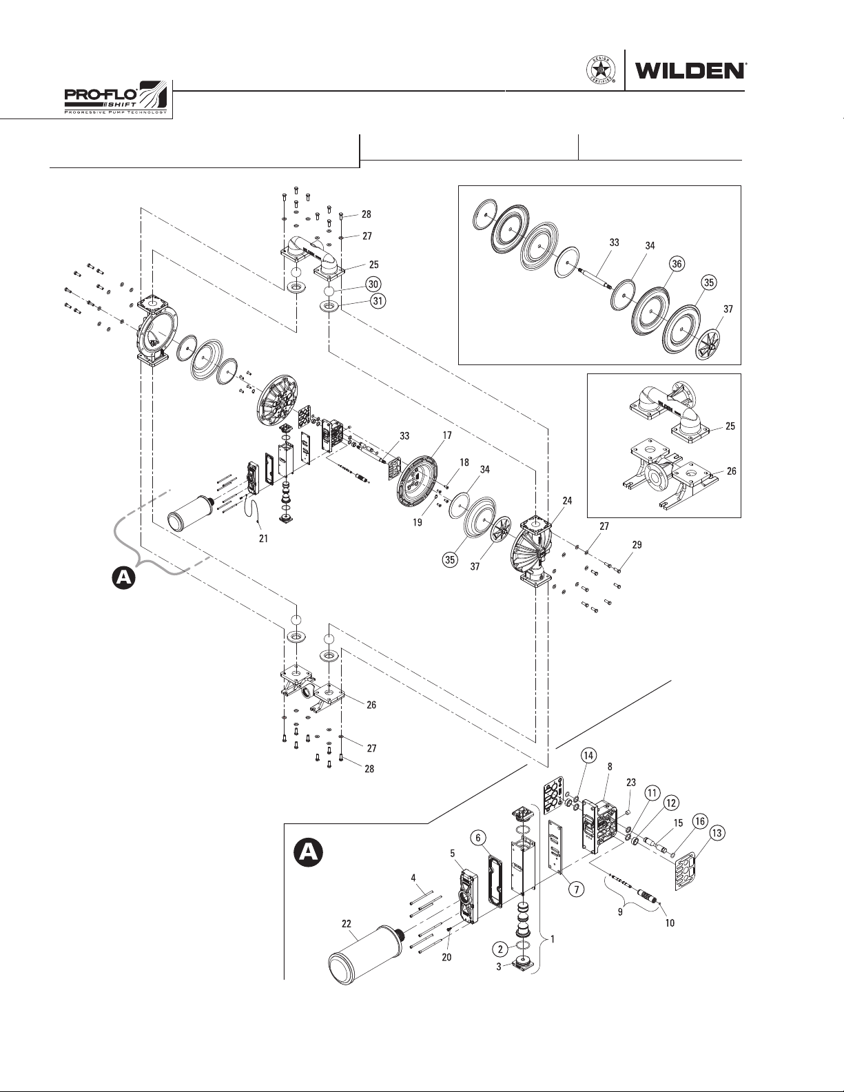
EXPLODED VIEW & PARTS LISTING
GPS820/GPS830 ALUMINUM
EXPLODED VIEW
FULL-STROKE PTFE
FLANGED
METAL ADS
LWO301 Rev. D
ALL CIRCLED PART IDENTIFIERS ARE INCLUDED IN REPAIR KITS
WILDEN PUMP & ENGINEERING, LLC 28 WIL-17 10 0 - E-02
Page 31
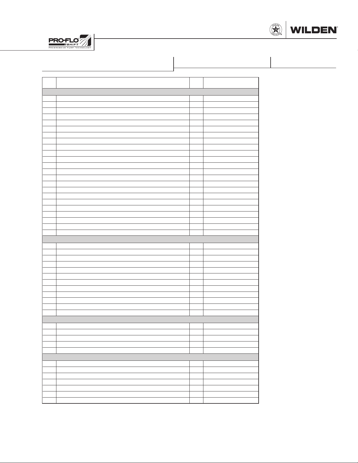
EXPLODED VIEW & PARTS LISTING
GPS820/GPS830 ALUMINUM
Item
Description Qty.
AIR DISTRIBUTION COMPONENTS
1 Air Valve Assembly, Pro-Flo® SHIFT
2 O-Ring, End Cap (-225, Ø1.859" x Ø.139") 2 04-2390-52-700
3 End Cap 2 04-2340-01
4 Screw, SHC, Air Valve (1/4"-20 x 4-1/2") 6 01-6000-03
5 Muffler Plate,Pro-Flo
6 Gasket, Muffler Plate, Pro-Flo
7 Gasket, Air Valve, Pro-Flo
®
SHIFT 1 04-3189-01
®
8 Center Block Assembly, Pro-Flo
9 Pilot Sleeve Assembly 1 04-3880-99
10 O-Ring, Pilot Spool Retaining (-009, Ø.208" x Ø.070") 2 04-2650-49-700
11 Seal, Shaft 2 08-3210-55-225
12 Bushing, Shaft 2 08-3306-13
13 Gasket, Center Block Pro-Flo V™ 2 04-3529-56
14 O-Ring, (-210, Ø.734" x Ø.139") 2 04-3209-49
15 Air Control Spool 1 04-3859-03
16 O-Ring, Air Control Spool Retaining (-114, Ø.612" x Ø.103") 2 04-3879-50
17 Air Chamber, Pro-Flo X™ Drop-In 2 08-3694-01
18 Screw, HSFHS (3/8"-16 x 1") 8 71-6250-08
19 Retaining Ring 2 04-3890-03
20 Grounding Screw, (10-32 x 1/2") Self Tapping 1 04-6345-08
21 Grounding Strap, CSA 1 01-8303-99
22 Muffler 1-1/2" MNPT 1 04-3518-99R
23 Plug, Pipe, 1/4" MNPT 1 00-7010-08
1
®
SHIFT 1 04-3509-52
SHIFT 1 04-2638-52
®
2
SHIFT
WETTED PATH COMPONENTS
24 Liquid Chamber, Bolted 2 08-5015-01
25 Manifold, Discharge (NPT) 1 08-5035-01
Manifold, Discharge (BSPT) 1 08-5036-01
Manifold, Discharge (ANSI) 1 08-5045-01
Manifold, Discharge (DIN) 1 08-5046-01
26 Manifold, Inlet (NPT) 1 08-5095-01
Manifold, Inlet (BSPT) 1 08-5096-01
Manifold, Inlet (ANSI) 1 08-5125-01
Manifold, Inlet (DIN) 1 08-5126-01
27 Washer, Flat (Ø.531" x Ø1.062" x .095") 32 04-6730-08
28 Screw, HHC (1/2"-13 x 1-3/4") 16 08-6190-08
29 Screw, HHC (1/2"-13 x 2") 16 04-6210-08
VALVE BALLS/VALVE SEATS/VALVE O-RINGS
30 Ball, Valve 4 08-1080-58
Ball, Valve, PTFE-Fitted 4 08-1080-55
31 Seat, Valve 4 08-1128-58
Seat, Valve, PTFE-Fitted 4 08-1129-01
32 O-Ring, Valve Seat PTFE-Fitted, (-347, Ø4.225 x Ø.210) (not shown) 4 08-1209-55
TPE/PTFE COMPONENTS
33 Shaft, Stallion 1 08-3848-03
Shaft, PTFE-Fitted 1 08-3812-03
34 Piston, Inner 2 08-3700-01
35 Diaphragm, Primary 2 08-1022-58
Diaphragm, Primary, PTFE-Fitted 2 08-1040-55-42
36 Diaphragm, Back-Up, PTFE-Fitted 2 08-1065-57
37 Piston, Outer 2 08-4550-01
1
Air Valve Assembly includes items 2 and 3.
2
Metal Center Block Assembly includes items 11, 12, 14, 15 and 16.
All boldface items are primary wear parts.
GPS820/830/AAAAA/…/
P/N
1 04-2039-01
1 04-3129-01
PARTS LISTING
LW0302 Rev. E
WI L-17 10 0 - E-02 29 WILDEN PUMP & ENGINEERING, LLC
Page 32
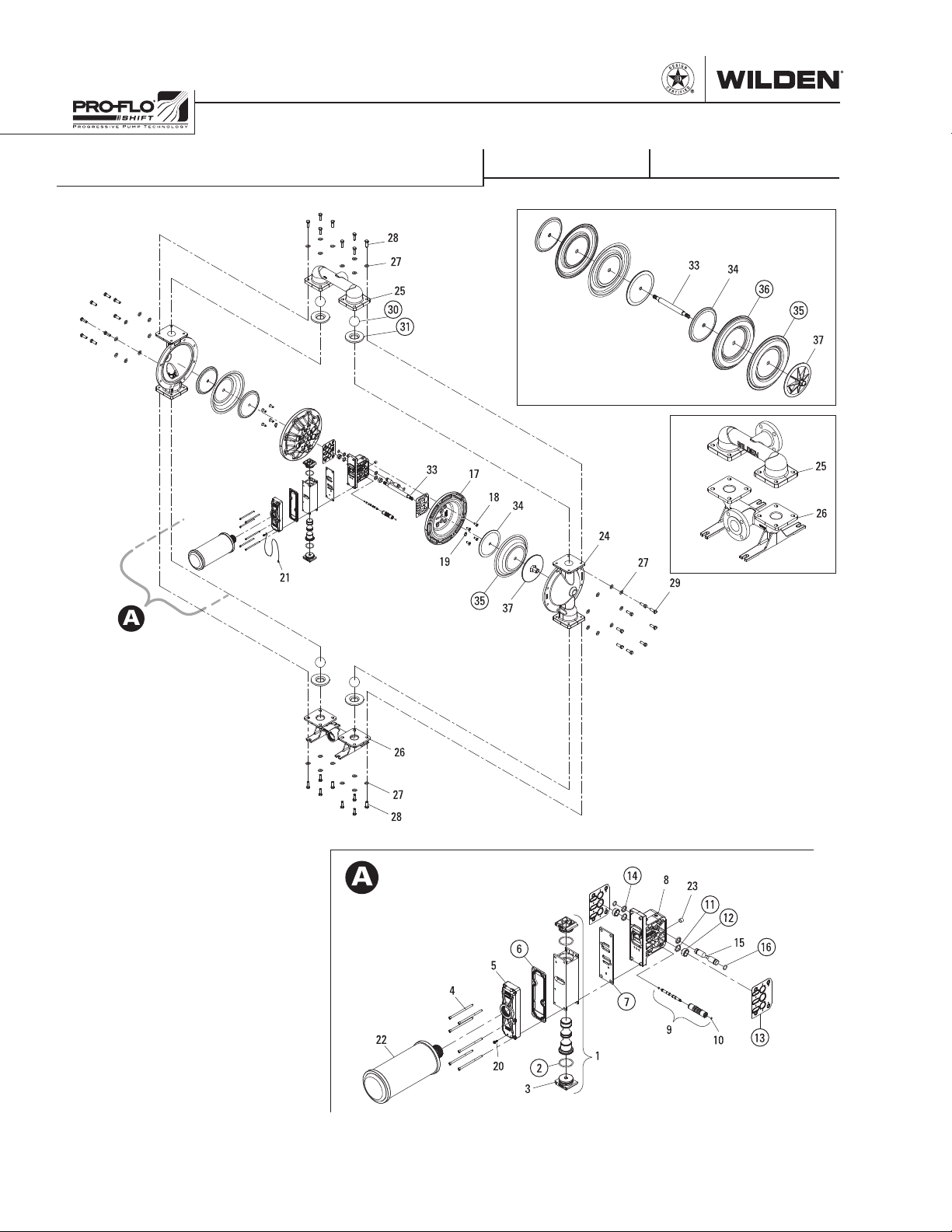
EXPLODED VIEW & PARTS LISTING
GPS820/GPS830 STAINLESS STEEL
EXPLODED VIEW
FULL-STROKE PTFE
FLANGED
METAL ADS
LWO303 Rev. C
ALL CIRCLED PART IDENTIFIERS ARE INCLUDED IN REPAIR KITS
WILDEN PUMP & ENGINEERING, LLC 30 WI L-17 10 0 - E-02
Page 33
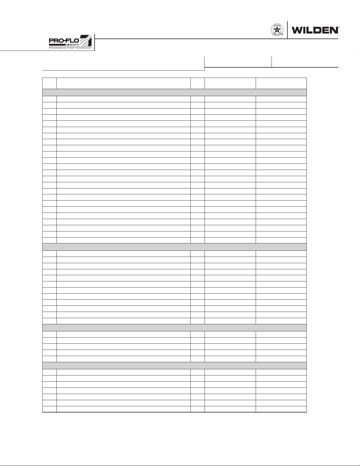
EXPLODED VIEW & PARTS LISTING
GPS820/GPS830 STAINLESS STEEL
Item
Description Qty.
GPS820/830/SSSAA/…/
P/N
PARTS LISTING
GPS820/830/SSSSS/…/
P/N
AIR DISTRIBUTION COMPONENTS
1 Air Valve Assembly, Pro-Flo® SHIFT
2 O-Ring, End Cap (-225, Ø1.859" x Ø.139") 2 04-2390-52-700 04-2390-52-700
3 End Cap 2 04-2340-01 04-2340-03
4 Screw, SHC, Air Valve (1/4"-20 x 4-1/2") 4 N/A 01-6000-03
Screw, SHC, Air Valve (1/4"-20 x 4-1/2") 6 01-6000-03 N/A
5 Muffler Plate, Pro-Flo
6 Gasket, Muffler Plate, Pro-Flo
7 Gasket, Air Valve, Pro-Flo
®
SHIFT 1 04-3189-01 04-3189-03
®
8 Center Block Assembly, Pro-Flo
9 Pilot Sleeve Assembly 1 04-3880-99 04-3880-99
10 O-Ring, Pilot Spool Retaining (-009, Ø.208" x Ø.070") 2 04-2650-49-700 04-2650-49-700
11 Seal, Shaft 2 08-3210-55-225 08-3210-55-225
12 Bushing, Shaft 2 08-3306-13 08-3306-13
13 Gasket, Center Block Pro-Flo V™ 2 04-3529-56 04-3529-56
14 O-Ring, (-210, Ø.734" x Ø.139") 2 04-3209-49 04-3209-49
15 Air Control Spool 1 04-3859-03 04-3859-03
16 O-ring, Air Control Spool Retaining (-114, Ø.612" x Ø.103") 2 04-3879-50 04-3879-50
17 Air Chamber, Pro-Flo X™ Drop-In 2 08-3698-03 08-3698-03
18 Screw, HSFHS (3/8"-16 x 1") 8 71-6250-08 71-6250-03
19 Retaining Ring 2 04-3890-03 04-3890-03
20 Grounding Screw, (10-32 x 1/2") Self Tapping 1 04-6345-08 04-6345-08
21 Grounding Strap, CSA 1 01-8303-99 01-8303-99
22 Muffler 1-1/2" MNPT 1 04-3518-99R 04-3513-99
23 Plug, Pipe, 1/4" MNPT 1 00-7010-08 00-7010-03
1
®
SHIFT 1 04-3509-52 04-3509-52
SHIFT 1 04-2638-52 04-2638-52
®
2
SHIFT
1 04-2039-01 04-2039-03
1 04-3129-01 04-3129-03
WETTED PATH COMPONENTS
24 Liquid Chamber, Bolted 2 08-5015-03 08-5015-03
25 Manifold, Discharge (NPT) 1 08-5035-03 08-5035-03
Manifold, Discharge (BSPT) 1 08-5036-03 08-5036-03
Manifold, Discharge (ANSI) 1 08-5045-03 08-5045-03
Manifold, Discharge (DIN) 1 08-5046-03 08-5046-03
26 Manifold, Inlet (NPT) 1 08-5095-03 08-5095-03
Manifold, Inlet (BSPT) 1 08-5096-03 08-5096-03
Manifold, Inlet (ANSI) 1 08-5125-03 08-5125-03
Manifold, Inlet (DIN) 1 08-5126-03 08-5126-03
27 Washer, Flat (Ø.531" x Ø1.062" x .095") 32 04-6730-03 04-6730-03
28 Screw, HHC (1/2"-13 x 1-1/2") 16 04-6180-03 04-6180-03
29 Screw, HHC (1/2"-13 x 2") 16 04-6210-03 04-6210-03
VALVE BALLS/VALVE SEATS/VALVE O-RINGS
30 Ball, Valve 4 08-1080-58 08-1080-58
Ball, Valve, PTFE-Fitted 4 08-1080-55 08-1080-55
31 Seat, Valve 4 08-1128-58 08-1128-58
Seat, Valve, PTFE-Fitted 4 08-1129-03 08-1129-03
32
O-Ring, Valve Seat PTFE-Fitted, (-347, Ø4.225 x Ø.210) (not shown)
4 08-1209-55 08-1209-55
TPE/PTFE COMPONENTS
33 Shaft, Stallion 1 08-3848-03 08-3848-03
Shaft, PTFE-Fitted 1 08-3812-03 08-3812-03
34 Piston, Inner 2 08-3700-01 08-3700-03
35 Diaphragm, Primary 2 08-1022-58 08-1022-58
Diaphragm, Primary, PTFE-Fitted 2 08-1040-55-42 08-1040-55-42
36 Diaphragm, Back-Up, PTFE-Fitted 2 08-1065-57 08-1065-57
37 Piston, Outer 2 08-4550-03 08-4550-03
1
Air Valve Assembly includes items 2 and 3.
2
Metal Center Block Assembly includes items 11, 12 and 14.
All boldface items are primary wear parts.
LW0304 Rev. F
WI L-17 10 0 - E-02 31 WILDEN PUMP & ENGINEERING, LLC
Page 34
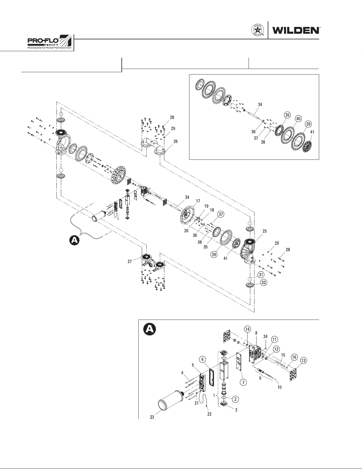
EXPLODED VIEW & PARTS LISTING
GPS1520 ALUMINUM
EXPLODED VIEW
34
28
29
26
FULL-STROKE PTFE-FITTED
34
17
19
18
39
20
36
38
27
37
35
39
41
36
37
38
25
35
40
39
41
29
28
14
8
6
5
4
7
1
21
23
22
2
3
ALL CIRCLED PART IDENTIFIERS ARE INCLUDED IN REPAIR KITS
31
32
24
11
12
15
16
13
9
10
METAL ADS
LWO305 Rev. D
WILDEN PUMP & ENGINEERING, LLC 32 WIL-1710 0 -E- 0 2
Page 35
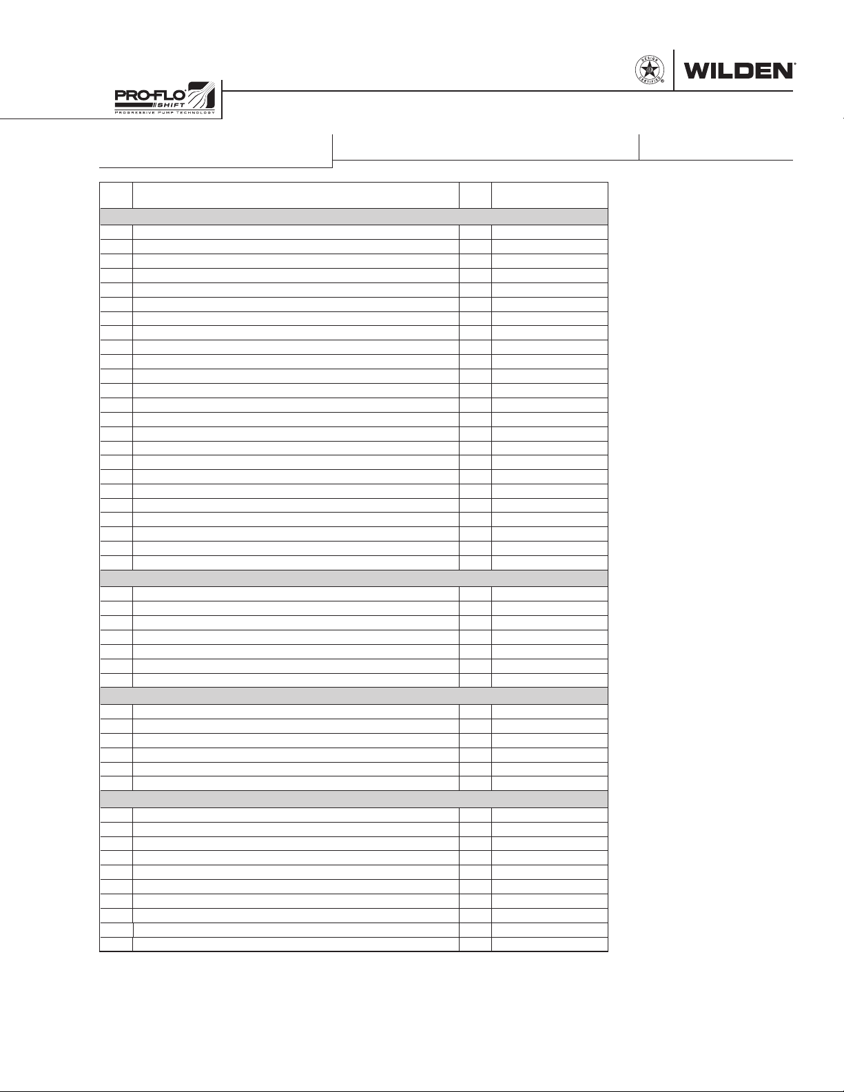
EXPLODED VIEW & PARTS LISTING
GPS1520 ALUMINUM
Item
Description Qty.
PARTS LISTING
GPS1520/AAAAA/…/
P/N
AIR DISTRIBUTION COMPONENTS
1 Air Valve Assembly, Pro-Flo® SHIFT
2 O-Ring, End Cap (-225, Ø1.859" x Ø.139") 2 04-2390-52-700
3 End Cap 2 04-2340-01
4 Screw, SHC, Air Valve (1/4"-20 x 4-1/2") 6 01-6000-03
5 Muffler Plate, Pro-Flo
6 Gasket, Muffler Plate, Pro-Flo
7 Gasket, Air Valve, Pro-Flo
®
SHIFT 1 04-3189-01
®
8 Center Block Assembly, Pro-Flo
9 Pilot Sleeve Assembly 1 15-3884-99
10 O-Ring, Pilot Spool Retaining (-009, Ø.208" x Ø.070") 2 04-2650-49-700
11 Seal, Shaft 2 15-3210-55-225
12 Bushing, Shaft 2 15-3306-13
13 Gasket, Center Block Pro-Flo
14 O-Ring, (-210, Ø.734" x Ø.139") 2 04-3209-49
15 Air Control Spool 1 15-3859-03
16 O-Ring, Air Control Spool Retaining (-114, Ø.612" x Ø.103") 2 04-3879-50
17 Air Chamber, Pro-Flo Shift™ 2 15-3694-01
18 Screw, HHC (3/8"-16 x 1-1/8") 8 15-6130-08
19 Washer, Flat (Ø.406" x Ø.812" x .065") 8 15-6740-08-50
20 Retaining Ring 2 04-3890-03
21 Grounding Screw, (10-32 x 1/2") Self Tapping 1 04-6345-08
22 Grounding Strap, CSA 1 01-8303-99
23 Muffler 1-1/2" MNPT 1 04-3518-99R
24 Plug, Pipe, 1/4" MNPT 1 00-7010-08
1
®
SHIFT 1 04-3509-52
SHIFT 1 04-2638-52
®
2
SHIFT
®
SHIFT 2 04-3529-56
1 04-2039-01
1 15-3129-01
WETTED PATH COMPONENTS
25 Liquid Chamber, Bolted 2 15-4980-01
26 Manifold, Discharge (NPT) 1 15-5035-01
Manifold, Discharge (BSPT) 1 15-5036-01
27 Manifold, Inlet (NPT) 1 15-5095-01
Manifold, Inlet (BSPT) 1 15-5096-01
28 Screw, HHC (5/8"-11 x 2") 40 15-6180-08
29 Washer, Flat (Ø.656" x Ø1.312" x .095") 40 15-6732-08
VALVE BALLS/VALVE SEATS/VALVE O-RINGS
30 Manifold Gasket, PTFE-Fitted (not shown) 4 15-1405-55
Ball, Valve 4 15-1080-58
31
Ball, Valve, PTFE-Fitted 4 15-1080-55
32 Seat, Valve 4 15-1126-58
Seat, Valve, PTFE-Fitted 4 15-1125-03
33 O-Ring, Valve Seat PTFE-Fitted (-250, Ø4.984" x Ø.139") (Not Shown) 4 15-1205-55
TPE/PTFE COMPONENTS
34 Shaft, Stallion 1 15-3848-03
Shaft, PTFE-Fitted 1 15-3805-09
35 Piston, Inner
2
36 Washer, Inner Piston Back-up 2 15-6850-08
37 Inner Piston Screw, HHC (3/8"-16 x 1-1/8") 12 15-6130-08
38 Inner Piston Washer (Ø.406" x Ø.812" x .065") 12 15-6740-08-50
39 Diaphragm, Primary 2 15-1022-58
Diaphragm, Primary, PTFE-Fitted 2 15-1040-55-42
40 Diaphragm, Back-Up, PTFE-Fitted 2 15-1065-57
41 Piston, Outer 2 15-4550-01
1
Air Valve Assembly includes items 2 and 3.
2
Metal Center Block Assembly includes items 11, 12, 14, 15 and 16.
All boldface items are primary wear parts.
15-3700-01
LW0306 Rev. E
WI L-17 10 0 - E-02 33 WILDEN PUMP & ENGINEERING, LLC
Page 36
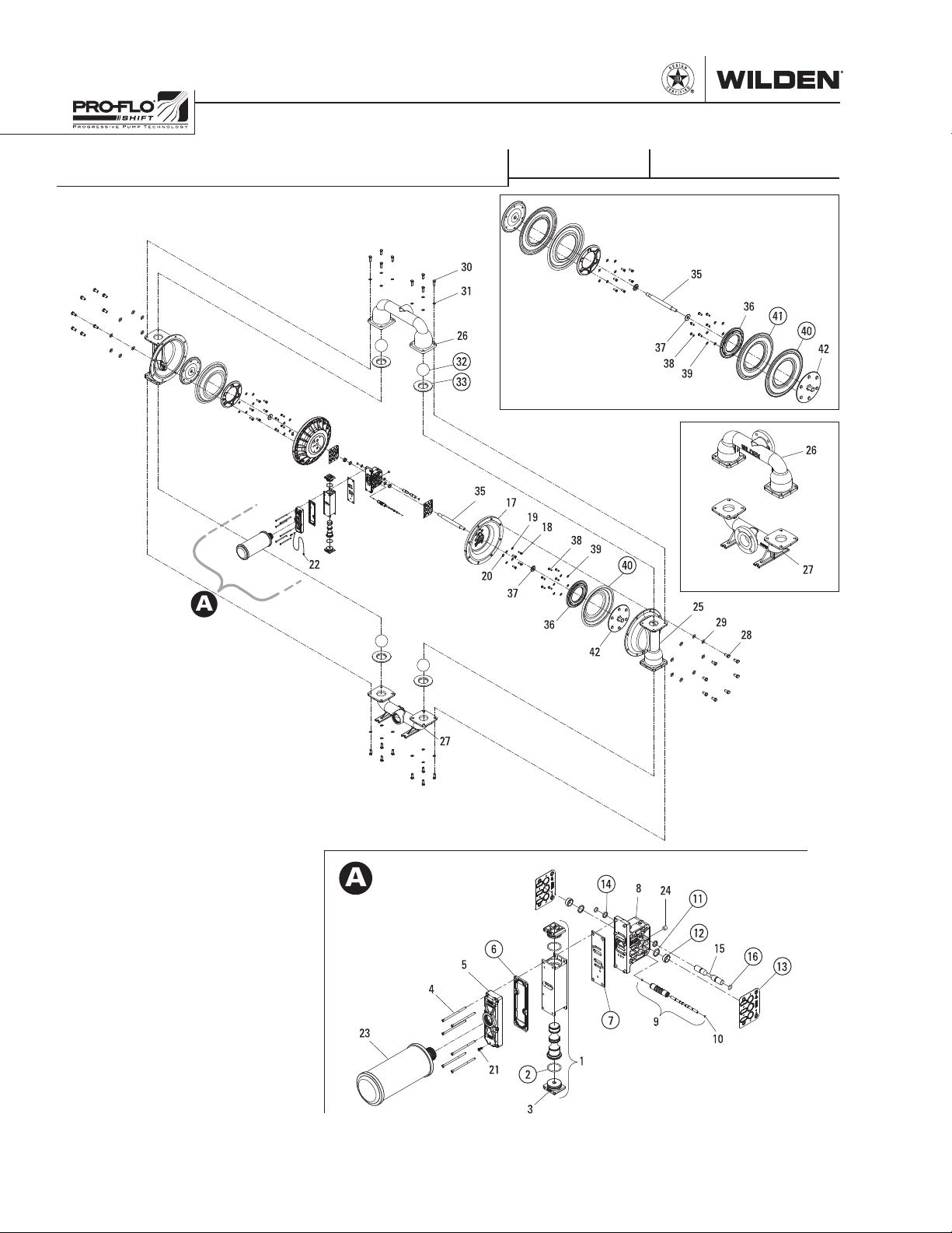
EXPLODED VIEW & PARTS LISTING
GPS1520/GPS1530 STAINLESS STEEL
EXPLODED VIEW
FULL-STROKE PTFE
FLANGED
METAL ADS
LWO307 Rev. C
ALL CIRCLED PART IDENTIFIERS ARE INCLUDED IN REPAIR KITS
WILDEN PUMP & ENGINEERING, LLC 34 WI L-1710 0 - E- 02
Page 37
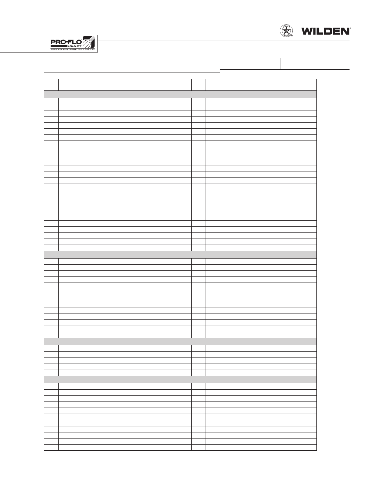
EXPLODED VIEW & PARTS LISTING
GPS1520/GPS1530 STAINLESS STEEL
Item
1 Air Valve Assembly, Pro-Flo® SHIFT
2 O-Ring, End Cap (-225, Ø1.859" x Ø.139") 2 04-2390-52-700 04-2390-52-700
3 End Cap 2 04-2340-01 04-2340-03
4 Screw, SHC, Air Valve (1/4"-20 x 4-1/2") 4 N/A 01-6000-03
Screw, SHC, Air Valve (1/4"-20 x 4-1/2") 6 01-6000-03 N/A
5 Muffler Plate, Pro-Flo
6 Gasket, Muffler Plate, Pro-Flo
7 Gasket, Air Valve, Pro-Flo® SHIFT 1 04-2638-52 04-2638-52
8 Center Block Assembly, Pro-Flo
9 Pilot Sleeve Assembly 1 15-3884-99 15-3884-99
10 O-Ring, Pilot Spool Retaining (-009, Ø.208" x Ø.070") 2 04-2650-49-700 04-2650-49-700
11 Seal, Shaft 2 15-3210-55-225 15-3210-55-225
12 Bushing, Shaft 2 15-3306-13 15-3306-13
13 Gasket, Center Block Pro-Flo V™ 2 04-3529-56 04-3529-56
14 O-Ring, (-210, Ø.734" x Ø.139") 2 04-3209-49 04-3209-49
15 Air Control Spool 1 15-3859-03 15-3859-03
16 O-Ring, Air Control Spool Retaining (-114, Ø.612" x Ø.103") 2 04-3879-50 04-3879-50
17 Air Chamber, Pro-Flo V™ 2 15-3690-03 15-3690-03
18 Screw, HHC (3/8"-16 x 1") 8 08-6130-03 08-6130-03
19 Washer, Flat (Ø.406" x Ø.812" x .065") 8 15-6740-08-50 04-6740-03
20 Retaining Ring 2 04-3890-03 04-3890-03
21 Grounding Screw, (10-32 x 1/2") Self Tapping 1 04-6345-08 04-6345-08
22 Grounding Strap, CSA 1 01-8303-99 01-8303-99
23 Muffler 1-1/2" MNPT 1 04-3518-99R 04-3513-99
24 Plug, Pipe, 1/4" MNPT 1 00-7010-08 00-7010-03
Description Qty.
AIR DISTRIBUTION COMPONENTS
1
®
SHIFT 1 04-3189-01 04-3189-03
®
SHIFT 1 04-3509-52 04-3509-52
®
2
SHIFT
GPS1520/1530/SSSAA/…/
P/N
1 04-2039-01 04-2039-03
1 15-3129-01 15-3129-03
GPS1520/1530/SSSSS/…/
PARTS LISTING
P/N
WETTED PATH COMPONENTS
25 Liquid Chamber, Bolted 2 15-5006-03 15-5006-03
26 Manifold, Discharge (NPT) 1 15-5035-03 15-5035-03
Manifold, Discharge (BSPT) 1 15-5036-03 15-5036-03
Manifold, Discharge (ANSI) 1 15-5045-03 15-5045-03
Manifold, Discharge (DIN) 1 15-5046-03 15-5046-03
27 Manifold, Inlet (NPT) 1 15-5095-03 15-5095-03
Manifold, Inlet (BSPT) 1 15-5096-03 15-5096-03
Manifold, Inlet (ANSI) 1 15-5125-03 15-5125-03
Manifold, Inlet (DIN) 1 15-5126-03 15-5126-03
28 Screw, HHC (5/8"-11 x 2") 16 15-6180-03 15-6180-03
29 Spring, Disk (5/8") 16 15-6820-03 15-6820-03
30 Screw, HHC (1/2"-13 x 1-1/2") 16 04-6180-03 04-6180-03
31 Spring, Disk (1/2") 16 15-6810-03 15-6810-03
VALVE BALLS/VALVE SEATS/VALVE O-RINGS
32 Ball, Valve 4 15-1085-58 15-1085-58
Ball, Valve, PTFE-Fitted 4 15-1085-55 15-1085-55
33 Seat, Valve 4 15-1128-58 15-1128-58
Seat, Valve, PTFE-Fitted 4 15-1129-03 15-1129-03
34
O-Ring, Valve Seat PTFE-Fitted (-358, Ø5.600" x Ø.210") (not shown)
4 15-1209-55 15-1209-55
TPE/PTFE COMPONENTS
35 Shaft, Stallion 1 15-3848-03 15-3848-03
Shaft, PTFE-Fitted 1 15-3805-09 15-3805-09
36 Piston, Inner 2 15-3700-01 15-3700-03
37 Washer, Inner Piston Back-up 2 15-6850-08 15-6850-08
38 Screw, HHC (3/8"-16 x 1-1/8") 12 15-6130-08 N/A
Screw, HHC (3/8"-16 x 1") 12 N/A 08-6130-03
39 Washer (Ø.406" x Ø.812" x .065") 12 15-6740-08-50 04-6740-03
40 Diaphragm, Primary 2 15-1022-58 15-1022-58
Diaphragm, Primary, PTFE-Fitted 2 15-1040-55-42 15-1040-55-42
41 Diaphragm, Back-Up, PTFE-Fitted 2 15-1065-57 15-1065-57
42 Piston, Outer 2 15-4550-03 15-4550-03
WI L-17 10 0 - E-02 35 WILDEN PUMP & ENGINEERING, LLC
LW0308 Rev. E
1
Air Valve
Assembly
includes
items 2 and 3.
2
Metal
Center Block
Assembly
includes
items 11, 12
and 14.
All boldface
items are
primary wear
parts.
Page 38
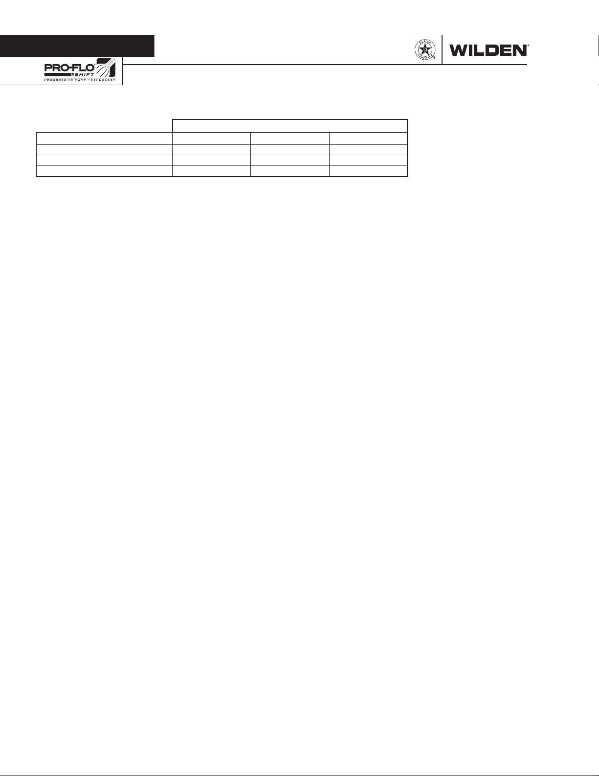
Section 9
REPAIR KITS
SIZE
Repair Kits 1.5" 2" 3"
Full-Stroke PTFE Wet Kit (TWS)* 04-9824-55-201 08-9824-55-201 15-9824-55-201
EZ-Install TPE Wet Kit (Z WS ) * 04-9824-58-209 08-9824-58-209 15-9824-58-209
Air Kit ** 04-9993-99-320 04-9993-99-320 15-9993-99-320
* Wet Kit includes primary diaphragms, back-up diaphragms (PTFE-fitted pumps only), valve balls and valve seat/O-rings.
** Air Kit includes air-valve spool assembly, end-cap O-rings, air-valve gasket, muffler-plate gasket, center-block gaskets, air
control spool seals and retaining O-rings, pilot sleeve assembly, snap rings, shaft Glyd-rings and bushings, grease kit.
NOTE: Metal seats are not included with wet kits.
WILDEN PUMP & ENGINEERING, LLC 36 WI L-17 10 0 - E-02
Page 39
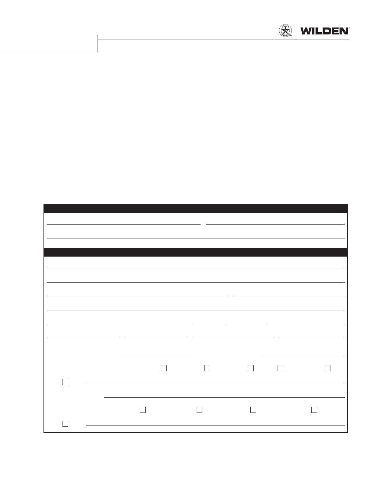
WARRANTY
Each and every product manufactured by Wilden Pump and Engineering, LLC is built to meet the highest
standards of quality. Every pump is functionally tested to insure integrity of operation.
Wilden Pump and Engineering, LLC warrants that pumps, accessories and parts manufactured or supplied by
it to be free from defects in material and workmanship for a period of five (5) years from date of installation or
six (6) years from date of manufacture, whichever comes first. Failure due to normal wear, misapplication, or
abuse is, of course, excluded from this warranty.
Since the use of Wilden pumps and parts is beyond our control, we cannot guarantee the suitability of any pump
or part for a particular application and Wilden Pump and Engineering, LLC shall not be liable for any consequential
damage or expense arising from the use or misuse of its products on any application. Responsibility is limited
solely to replacement or repair of defective Wilden pumps and parts.
All decisions as to the cause of failure are the sole determination of Wilden Pump and Engineering, LLC.
Prior approval must be obtained from Wilden for return of any items for warranty consideration and must be
accompanied by the appropriate MSDS for the product(s) involved. A Return Goods Tag, obtained from an
authorized Wilden distributor, must be included with the items which must be shipped freight prepaid.
The foregoing warranty is exclusive and in lieu of all other warranties expressed or implied (whether written or oral)
including all implied warranties of merchantability and fitness for any particular purpose. No distributor or other
person is authorized to assume any liability or obligation for Wilden Pump and Engineering, LLC other than expressly
provided herein.
PLEASE PRINT OR TYPE AND FAX TO WILDEN
PUMP INFORMATION
Item # Serial #
Company Where Purchased
YOUR INFORMATION
Company Name
Industry
Name Title
Street Address
City State Postal Code Countr y
Telephone Fax E-mail Web Addres s
Number of pumps in facility? Number of Wilden pumps?
Types of pumps in facility (check all that apply): Diaphragm
Media being pumped?
Other
Centrifugal
Gear
Submersible
Lobe
How did you hear of Wilden Pump?
Other
Trade Journal
Trade Show
Internet/ E-mail
Distributor
ONCE COMPLETE, FAX TO (909) 783-3440
OR GO TO PSGDOVER.COM > WILDEN > SUPPORT TO COMPLETE THE WARRANTY REGISTRATION ONLINE
NOTE: WARRANTY VOID IF PAGE IS NOT FAXED TO WILDEN OR SUBMIT TED ONLINE VIA THE PSGDOVER.COM WEBSITE
WILDEN PUMP & ENGINEERING, LLC
Page 40

Where Innovation Flows
22069 Van Buren Street,
Grand Terrace, CA 92313-5607
Telephone: (909) 422-1731
Fax: (909) 783-3440
22069 Van Buren St., Grand Terrace, CA 92313-5607
P: +1 (909) 422-1730
• F: +1 (909) 783-3440
PSG
wildenpump.com
PSG® reserves the right to modify the information and illustrations contained in this document without prior notice. This is a non-contractual document. 03-2016
Authorized PSG Representative:
Copyrigh t ©2016, PS G®, A Dover Compa ny
WI L-1710 0- E-0 2
RE PLA CES WIL-17 100 -E -01
 Loading...