

Page 1

user manual
EvoBoost
Page 2

contents
contents
introduction 3
Overview 3
1. safety 4
2. description 5
3. contents of packaging 6
4. dimensions and specifications 6
5. installation 7
5.1 Site surveys and installation requirements 7
5.2 Installation for up to 3x EvoClean dispensers 8
6. set up 11
7. operation 12
8. maintenance 12
9. troubleshooting 14
10. spares and repair 15
11. warranty 16
12. decommissioning and disposing 16
13 electrical approvals 16
14 water approvals 17
15 WEEE - waste electrical & electronic equipment 17
Page 2 Hydro Systems Co. 2019HYD10099044 Rev 1.4
Page 3

introduction
Please look at and read these instructions carefully before starting installation and operation. Keep the Installation and User
Manual for future reference.
Remove all packaging and check the EvoBoost for damage or missing parts, against the Contents of Packaging, before
starting installation.
Any alterations made to the EvoBoost and fittings will invalidate the Warranty.
Overview
The EvoBoost is a sleek booster tank that compliments OPL installs. The system is designed to mitigate poor water
pressure and flow that can impact the performance of Laundry Chemical dispensers. With the EvoBoost installed, chemical
delivery will be consistent and extremely accurate, leading to predictable laundry results.
HYD10099044 Rev 1.4
Page 3 Hydro Systems Co. 2019
Page 4

1. safety
Safety Precautions
THANK YOU FOR YOUR INTEREST IN OUR PRODUCTS.
TO AVOID SERIOUS PERSONAL INJURY AND PROPERTY DAMAGE:
WARNING
WEAR
• please use this equipment carefully and observe all warnings and cautions as detailed within
this manual before installation or operation of this equipment.
• all electrical work should be carried out by a qualified Electrician, in accordance with local
and national regulations.
• isolate power & water supply to this equipment before connection / disconnection of
water connections and / or maintenance on this unit and / or dispensers supplied by this
unit.
• ensure all plumbing is installed correctly before turning on power & water to the unit.
• to avoid damage to the unit, ensure dispensers connected to the EvoBoost are not used
whilst the water supply is isolated.
• the EvoBoost should be operated within the correct voltage range as listed in the Manual.
• the installer and user are responsible for ensuring the installation and operation of this unit
are in accordance with this Installation and User Manual and local and national regulations.
• the unit should only be used within the following temperature range: 5-40°C / 41-104°F.
• the unit is only to be installed and used indoors.
• means for connection of the appliance from the supply mains must be incorporated within
the fixed wiring in accordance with the wiring rules.
• if the supply cord is damaged, it must be replaced by the manufacturer, its service agent or
similarly qualified persons to avoid a hazard.
• this unit is not to be used in an ATEX environment.
• ensure unit overflow is connected to a drain point
• the appropriate protective clothing and eye wear when installing and operating this
equipment or when handling or dispensing chemicals or other materials or when working in
the vicinity of all chemicals, filling or emptying equipment or changing metering tips.
ALWAYS
NEVER
This unit is designed to be used with temperatures of 5-40°C / 41-104°F
Water pressures must be between 1 bar (14.5 psi) and 6 bar (87 psi)
• read and follow all safety instructions in safety data sheets (SDS) for all chemicals.
• observe safety and handling instructions of the chemical manufacturer.
• dilute and dispense chemicals in accordance with manufacturer’s instructions.
• direct discharge away from you or other persons and into approved containers.
• regularly inspect equipment and keep equipment clean and properly maintained.
• mix incompatible chemicals that pose hazards.
Page 4 Hydro Systems Co. 2019HYD10099044 Rev 1.4
Page 5
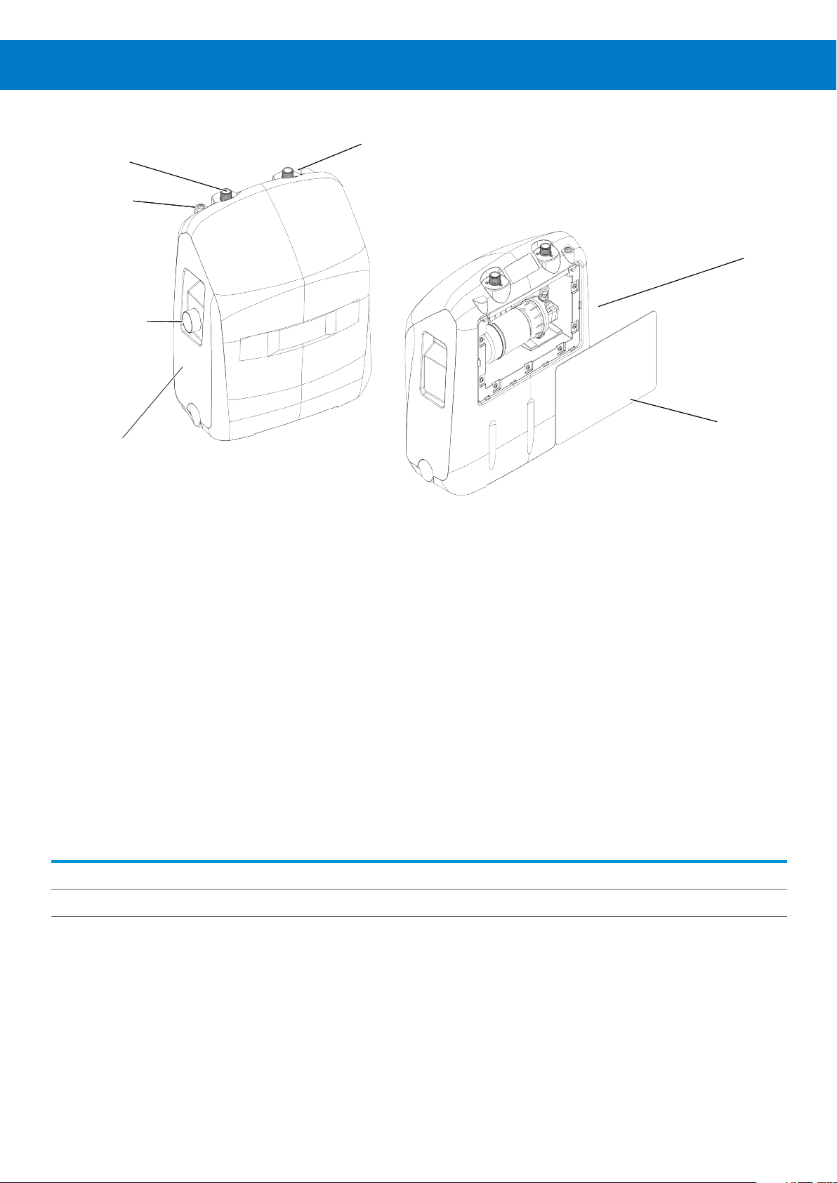
2. description
Water outlet
Power cable
3M (10ft) long
Overflow fitting
Water tank
Water inlet
Pump
Rear cover
The EvoBoost is designed to supply laundry dispensers (max. 3 low flow EvoClean’s) with 2.5 bar (35 psi) consistently.
With the EvoBoost installed, chemical delivery will be consistent and extremely accurate, leading to predictable laundry
results. The key features of the unit are as follows:
• The EvoBoost is equipped with a powerful and reliable electric diaphragm pump in either 230VAC or 115 VAC versions
with a flow rate of 6.1 LPM (1.6 GPM).
• The EvoBoost is small and compact and specifically designed for OPL applications. It is designed to sit neatly on the
floor near the chemical containers and has a clean aesthetic.
• The air gap on the water inlet of the EvoBoost provides a physical air break between the incoming potable water
supply and the main water reservoir.
• Although it has been designed for a laundry use case, the EvoBoost is versatile and flexible to be used with any venturi
dispenser
• The EvoBoost pump will run when a valve on the dispenser opens until the pressure reaches 5.5 bar (80 psi), at which
point, the integrated pressure switch turns it off.
Part Number Description Inlet Fitting Outlet Fitting Voltage
EVB1561115VG EvoBoost 115v 3/4 GH, Female 3/4 GH, Male 115 VAC
EVB1561230VB EvoBoost 230v 3/4 BSP, Male 3/4 BSP, Male 230 VAC
HYD10099044 Rev 1.4
Page 5 Hydro Systems Co. 2019
Page 6
3. contents of packaging
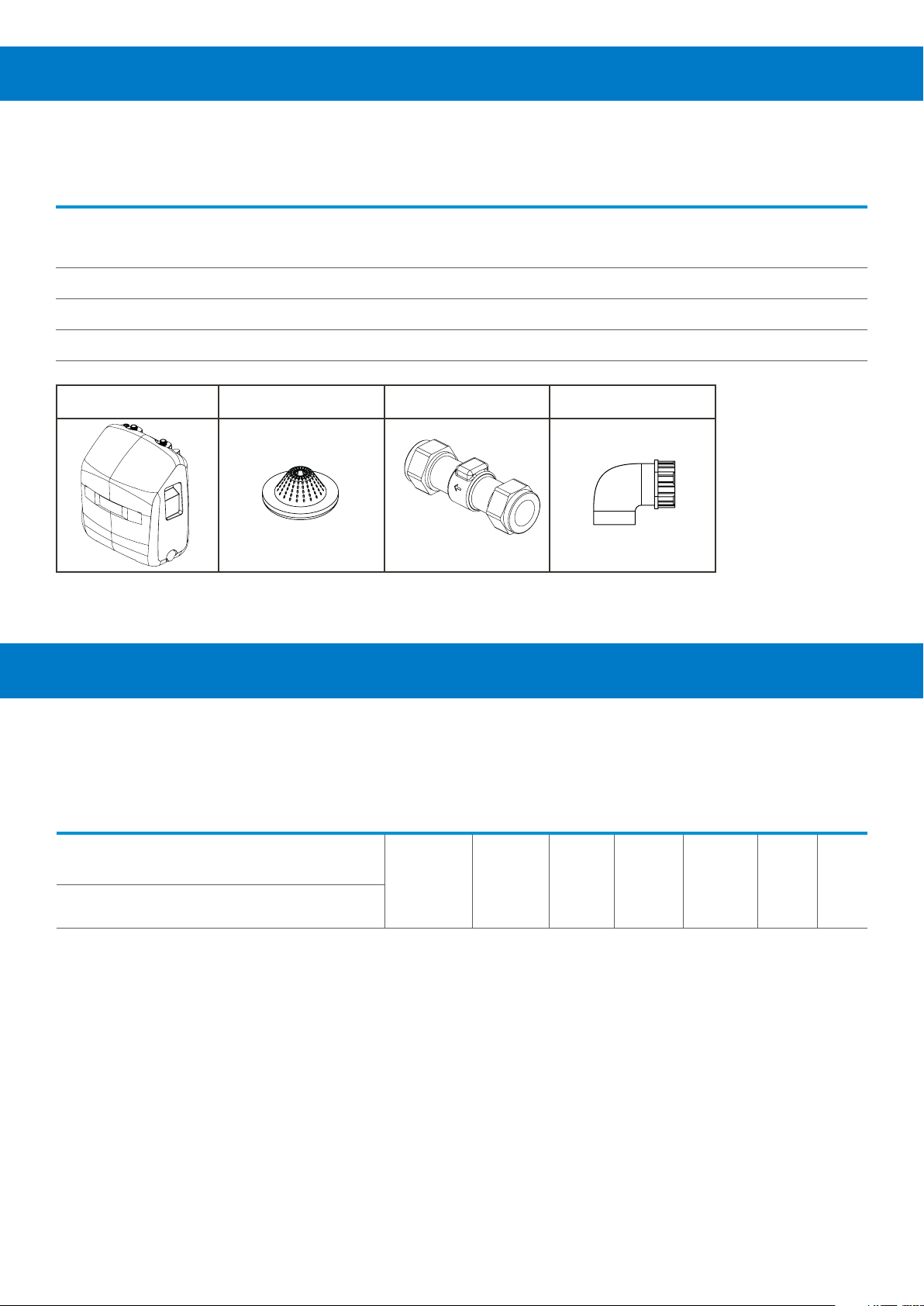
Packaging contains:
Item Description
EVB1561230VB EVB1561115VG
1a EvoBoost
2a Strainer Washer
3a 15mm Double Check Valve
4a Waste Pipe Elbow
1a 2a 3a 4a
1x 1x
1x 1x
1x
1x 1x
• For installation kits and spare parts please see page 17
4. dimensions & specifications
Model Power Current Appliance
Class
(Amps) (°C/°F) Gross Net
EVB1561115VG 115 V/AC 0.6 Class I
EVB1561230VB 230 V/AC 0.4 Class I
NOTE: Back pressure on the outlet of the pump is not to exceed 4.8 bar (70 psi) dynamic.
CAUTION: The duty cycle of the pump must not exceed 50% max with a 2-minute maximum run time per
cycle. Running the pump at or near its max duty cycle will shorten the life of the pump.
Operating
temperature
5-40°C
41-104°F
Inlet
Pressure
Min. 1 Bar
(14.5 psi)
Max. 6 Bar
(87 psi)
Outlet
Pressure
5.5 Bar
(80 psi)
Inlet
Flow
6 LPM
1.6 GPM
Outlet
Flow
7.1 LPM
1.9 GPM
Package weight
(kg/lbs)
8kg
17.6lbs
6.2kg
13.7lbs
Page 6 Hydro Systems Co. 2019HYD10099044 Rev 1.4
Page 7

490
[19.3]
[19.5]
496
[10.4]
264.6
5. installation
5.1 Site services and installation requirements
Safety
• Please read section 1 – Safety, carefully, prior to installation, to ensure all precautions have been adhered to.
• The unit must be installed by a trained Engineer.
• Any electrical work must be carried out by a trained electrician according to applicable electrical codes & regulations.
• Ensure all plumbing is installed in accordance with applicable codes & regulations.
• Ensure overflow on unit is connected to a drain point
Prior to installation, complete a site survey to ensure that the proposed site meets the following requirements:
• Ensure the flooring to mount the EvoBoost is of solid construction, stable, level and can accommodate the weight of
the product when filled with water (~26kg/57lbs).
• There is a 115 / 230V mains supply available within 3 meters (10ft) of the installation location.
• There is a mains water supply available within 2 meters (6.5ft) of the installation location and can provide a minimum
Inlet flow of 6Lpm (1.6 GPM) at 1 Bar (14.5 psi) pressure. Water pressure shall not exceed 6 bar (87 psi).
• There is sufficient room for installation of the EvoBoost.
• EvoClean units are / can be installed as per the dimensional requirements listed in the installation section in this manual
• There is a drain point near the EvoBoost to allow for the overflow to be connected.
The tools that are required to complete the installation are:
HYD10099044 Rev 1.4
Flat Head
Page 7 Hydro Systems Co. 2019
Page 8

5.2 Installation for up to 3x EvoClean dispensers
The following installation suggestions outline the method of connecting the EvoBoost to the mains water supply & up to 3
x EvoClean units.
A range of installation kits can be purchased to assist with a quick, neat & professional installation, that
achieve the 3 options listed below. Details of kits are listed within the manual; please contact your local sales
representative for further information.
• Please ensure the distances between the EvoClean dispensers and EvoBoost unit are adhered to, in order to maintain
correct operation.
• Minimum pipe internal diameter should be 8mm. Anything smaller may affect function & wash results.
• Ensure all plumbing connections are tightened sufficiently / sealed correctly, to ensure there are no leaks.
• Ensure there are no kinks in the water delivery hoses. This will affect function & wash results and reduce the life of the
pump in the EvoBoost.
• Ensure all plumbing is connected before switching on the EvoBoost unit
• Ensure both the EvoBoost & EvoClean units are isolated (power & water) and de-pressurised before servicing or
maintaining either unit.
Setting up the EvoBoost:
• Position the EvoBoost in the desired location for install.
• Ensure the strainer washer is fitted to the INLET side of the EvoBoost (as illustrated)
NOTE: STRAINER WASHER MUST BE FITTED IN ORDER FOR THE PRODUCT TO WORK EFFECTIVELY.
1. EVB1561230VB 2. EVB1561115VG
water inlet
• Ensure the waste pipe elbow is fitted to the OVERFLOW OUTLET on the side of the EvoBoost (as illustrated in the
recommended setup diagrams)
Setup of the EvoClean dispensers:
The EvoClean setup should be followed in the ‘EvoClean Installation and Operation manual’, this gives a more comprehensive
setup of the system. Install the EvoClean units in accordance with the dimensional information given below in relation to
distances from the EvoBoost.
Installation of EvoBoost plumbing:
• Connect the EvoBoost in accordance with the diagram below, adhering to the dimensions indicated.
• A serviceable water filter (approx. 105 micron) (not provided) should be used on the incoming mains supply.
• Each numbered item in next image is referenced from table “contents of packaging”.
Page 8 Hydro Systems Co. 2019HYD10099044 Rev 1.4
Page 9

1x EvoClean
3
B
EVB1561230VB 230V BSP
Max horizontal distance from
Point “A” to Point “B” is 3m (10ft)
1
CONNECT
OVERFLOW
TO DRAIN
2x EvoClean
2
MAX. 1.6M / 5.5FT
4a
3
A
4/2a
1a
5 3a
WATER FILTER (105 MICRON) CUSTOMER SUPPLIED
3
BB
EVB1561230VB 230V BSP
WATER MAIN
2
MAX. 1.6M / 5.5FT
4a
CONNECT
OVERFLOW
TO DRAIN
Max horizontal distance from
Point “A” to Point “B” is 3m (10ft)
1
2
A
6
4/2a
1a
5
WATER FILTER (105 MICRON) CUSTOMER SUPPLIED
3a
WATER MAIN
HYD10099044 Rev 1.4
Page 9 Hydro Systems Co. 2019
Page 10
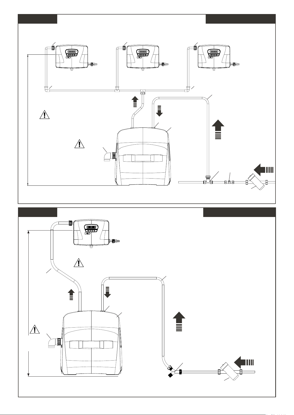
3x EvoClean EVB1561230VB 230V BSP
3
7
Max horizontal distance from
Point “A” to Point “B” is 3m (10ft)
MAX. 1.6M / 5.5FT
CONNECT
OVERFLOW
TO DRAIN
4a
3
BB
A
4/2a
1a
3
B
7
1
WATER MAIN
5
3a
WATER FILTER (105 MICRON) CUSTOMER SUPPLIED
1 x EvoClean EVB1561115VG 115V GHV
B
Max distance from Point "A"
Max horizontal distance from
to Point "B" is 12 Ft (3.5 M)
Point “A” to Point “B” is 3m (10ft)
9
MAX. 1.6M / 5.5FT
4a
CONNECT
OVERFLOW
TO DRAIN
A
4/2a
1a
9
WATER MAIN
10
WATER FILTER (105 MICRON) CUSTOMER SUPPLIED
Page 10 Hydro Systems Co. 2019HYD10099044 Rev 1.4
Page 11
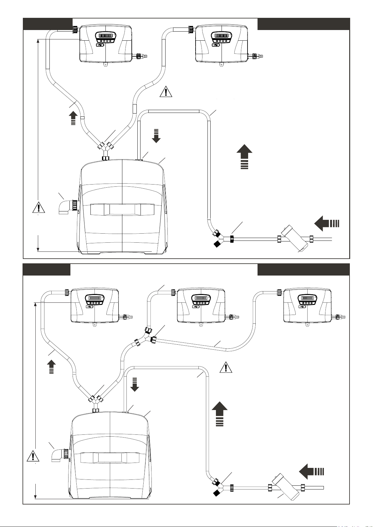
2x EvoClean
B B
Max horizontal distance from
Max distance from Point "A"
Point “A” to Point “B” is 3m (10ft)
to Point "B" is 12 Ft (3.5 M)
EVB1561115VG 115V GHV
MAX. 1.6M / 5.5FT
4a
CONNECT
OVERFLOW
TO DRAIN
3x EvoClean
9
10
A A
4/2a
1a
WATER FILTER (105 MICRON) CUSTOMER SUPPLIED
9
WATER MAIN
10
EVB1561115VG 115V GHV
9
B B B
9
MAX. 1.6M / 5.5FT
4a
CONNECT
OVERFLOW
TO DRAIN
10
A A
4/2a
1a
10
9
Max horizontal distance from
Max distance from Point "A"
Point “A” to Point “B” is 3m (10ft)
to Point "B" is 12 Ft (3.5 M)
9
WATER MAIN
10
HYD10099044 Rev 1.4
WATER FILTER (105 MICRON) CUSTOMER SUPPLIED
Page 11 Hydro Systems Co. 2019
Page 12
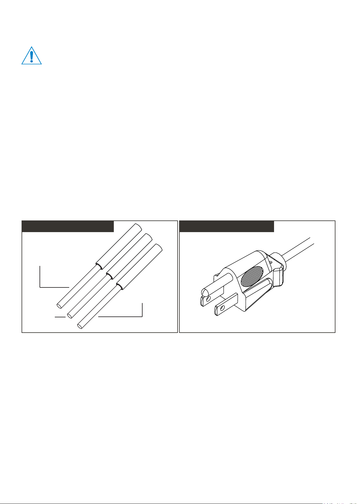
5.3 Electrical connection
• All electrical work should be carried out by a qualified Electrician, in accordance with local and national
regulations.
• Isolate power & water supply to this equipment before connection / disconnection of water connections
and / or maintenance on this unit and / or dispensers supplied by this unit.
• To avoid damage to the unit, ensure dispensers connected to the EvoBoost are not used whilst the water
supply is isolated.
• The EvoBoost should be operated within the correct voltage range as listed in the Manual.
• Means for connection of the appliance from the supply mains must be incorporated within the fixed wiring
in accordance with the wiring rules.
• The installer and user are responsible for ensuring the installation and operation of the EvoBoost & EvoClean
units are in accordance with this Installation and User Manual (and EvoClean manual) and local and national
regulations.
• If the supply cord is damaged, it must be replaced by the manufacturer, its service agent or similarly qualified
persons to avoid a hazard.
Note: It is a legal requirement to allow disconnection of the appliance from the supply after installation. The disconnection
may be achieved by having the plug accessible or by incorporating a switch in the fixed wiring in accordance with the wiring
rules.
Connecting the mains power supply
1. EVB1561230VB (230 VAC) 2. EVB1561115VG (115 VAC)
BROWN (LIVE)
GREEN (EARTH)
BLUE
(NEUTRAL)
PLUG 115v US
Page 12 Hydro Systems Co. 2019HYD10099044 Rev 1.4
Page 13

6. set up
EvoBoost
Plumbing and power has been correctly connected according to the installation section. Once this is complete:
• Open the isolation valve connecting the EvoBoost to the water main.
• Allow the EvoBoost water reservoir to fill (this can take up to 15 minutes depending on water inlet flow).
• Check for leaks in the system plumbing on the inlet side of the unit.
• Turn on the power to the EvoBoost. The pump will activate, and you will hear it running.
• With a pressure gauge, check the delivery pressure on the EvoBoost when the valve on the destination device is open.
The water pressure during delivery must be below 4.8 bar (70 psi) or there is too much backpressure for the pump to
operate properly.
• The plumbing between the EvoBoost and EvoClean will pressurise until the pressure switch on the pump cuts out.
• Check for leaks in the system plumbing between the EvoBoost and EvoClean.
• Using the ‘prime chemicals’ feature on the EvoClean, operate the flush valve for approximately 30 seconds to flush
through any trapped air in the system.
• Repeat this process with all EvoClean units in the system (up to 3).
EvoClean
The EvoClean setup should be followed in the ‘EvoClean Installation and Operation manual’, this gives a more comprehensive
setup of the system. Once the EvoClean unit has been programmed correctly, the following quick start steps can be taken:
• Prime each chemical to the top of each chemical pickup tube.
• Calibrate each chemical to ensure that the dosage is accurate.
HYD10099044 Rev 1.4
Page 13 Hydro Systems Co. 2019
Page 14
7. operation
Operating the EvoClean dispensers
Once the EvoBoost has been setup (as per setup section), the EvoClean units will be ready to operate in a wash cycle. The
EvoBoost will automatically run every time the EvoClean operates, through use of a built-in pressure switch. The EvoBoost
will shut off automatically once the EvoClean unit stops dosing.
8. maintenance
ENSURE BOTH THE EVOBOOST & THE EVOCLEAN UNITS ARE ISOLATED (POWER & WATER)
AND DE-PRESSURISED BEFORE SERVICING OR MAINTAINING EITHER UNIT.
Every 3 Months
• Verify that the pump is running smoothly without constant interruption.
• Check inlet & outlet plumbing to ensure not leaks have formed.
• Clean the unit with a damp cloth and remove dust, lint and dirt.
Every 6 Months
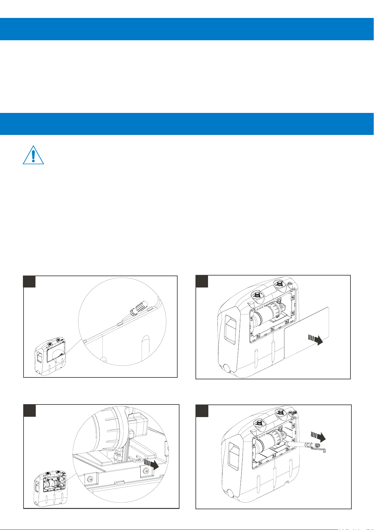
Clean the pump pickup tube & use a cleaning tablet to clean the inside of the tank:
Remove Rear cover using flathead screwdriver to
CAREFULLY pry the lower clips open.
1
Remove securing clip for pickup tube Remove hose using handle WARNING TAKE CARE NOT
3
Remove rear cover
2
TO DROP THE PICKUP HOSE INTO THE WATER TANK
4
Page 14 Hydro Systems Co. 2019HYD10099044 Rev 1.4
Page 15
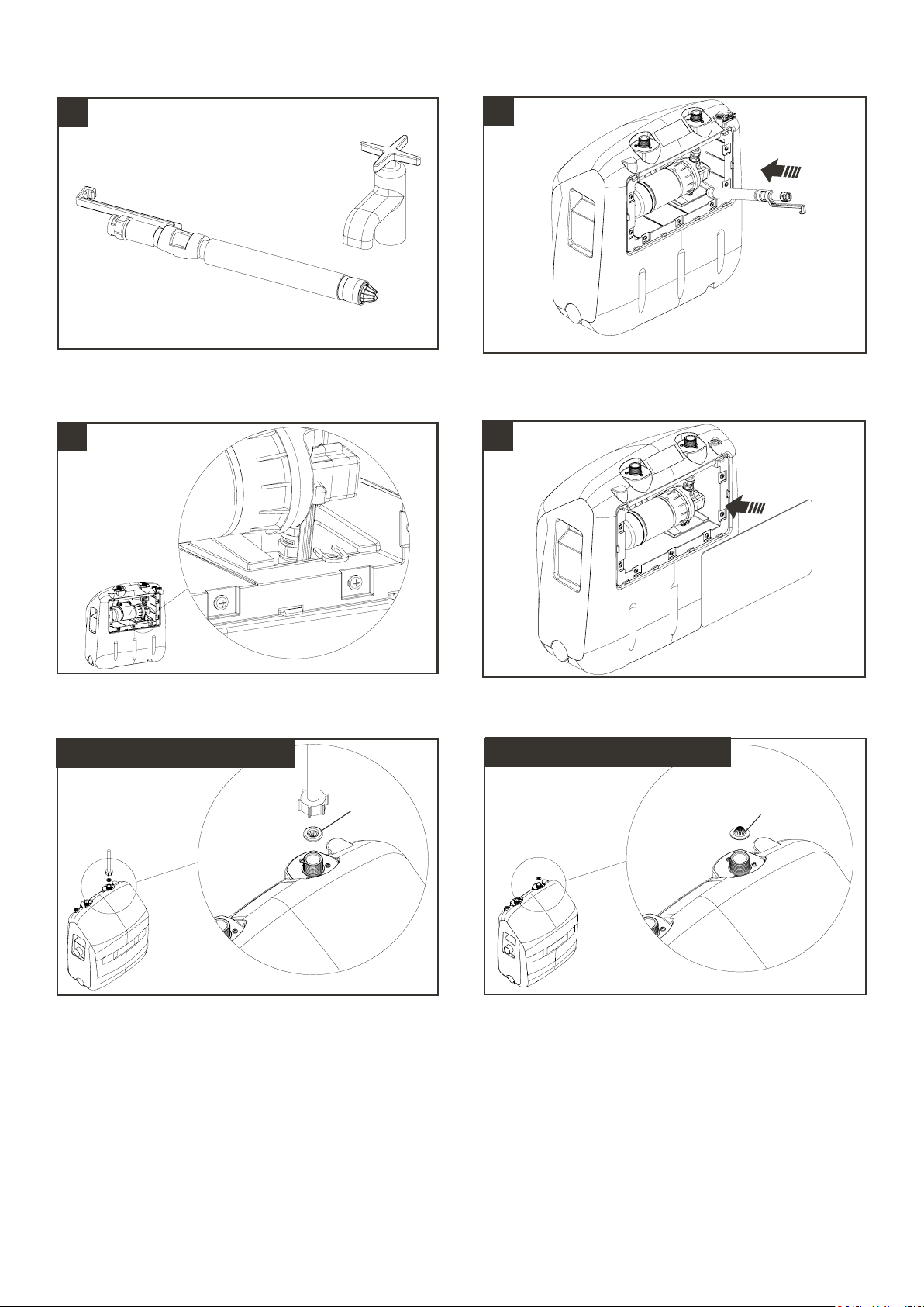
Clean pickup tube, removing any film, particles, dirt that
may have built up.
Clean inside of tank and lower the pickup tube back into
the tank WARNING TAKE CARE NOT TO DROP THE
PICKUP HOSE INTO THE WATER TANK
5
Replace securing clip back onto pickup tube WARNING
TAKE CARE NOT TO DROP THE SECURING CLIP INTO
THE WATER TANK
7
6
Replace rear cover
8
Clean the inlet strainer washer on the EvoBoost:
1. EVB1561230VB (230 VAC)
clean
2. EVB1561115VG (115 VAC)
clean
HYD10099044 Rev 1.4
Page 15 Hydro Systems Co. 2019
Page 16

9. troubleshooting
Error Possible Cause Possible Resolution
• Pump running is much louder than
usual
• Pump running intermittently • Excess backpressure in the
• Excess vibration • Hose vibration touching another
• EvoClean not delivering chemical
or inadequate flushing
• Pump pickup tube possibly
blocked
system (>4.8bar/70 psi) is causing
the pump to cut out.
surface and amplifying sound
• EvoBoost not connected to power
source or not turned on
• Tank has run out of water • Ensure water supply to EvoBoost
• Follow maintenance procedure for
cleaning pickup tube & cleaning
tank
• Check installation meets the
requirements outlined in the
‘installation’ section of the manual
• Check hoses are not kinked or
there aren’t restrictions in the
installation pipework
• Clean the strainer washer on the
water inlet to the EvoClean. This
may have become blocked
• Ensure outlet pipework & hoses
are secured correctly to a solid
surface and are not touching other
equipment
• Check EvoBoost unit is connected
correctly to the mains power
supply
is on and there is sufficient flow
and pressure (see specification)
• Inlet strainer washer to EvoBoost
may have blocked. Clean
inlet strainer washer as per
‘Maintenance’ section of the
manual
• Pump not switching off • Water tank has run dry • Ensure water supply to EvoBoost
is on and there is sufficient flow
and pressure (see specification)
• Tank overflowing • Float valve has become blocked
due to incorrect filtering of water
• Pump not priming on start up • Air lock in system • Disconnect hose from the
• Isolate incoming water and
electricity supply and contact your
local sales representative
Evoclean unit and route the hose
to container on floor (the container
must be the same level as the
EvoBoost unit). Turn the pump on
until the water runs through into
the container. The hose can then
be reconnected to the Evoclean
unit.
Page 16 Hydro Systems Co. 2019HYD10099044 Rev 1.4
Page 17
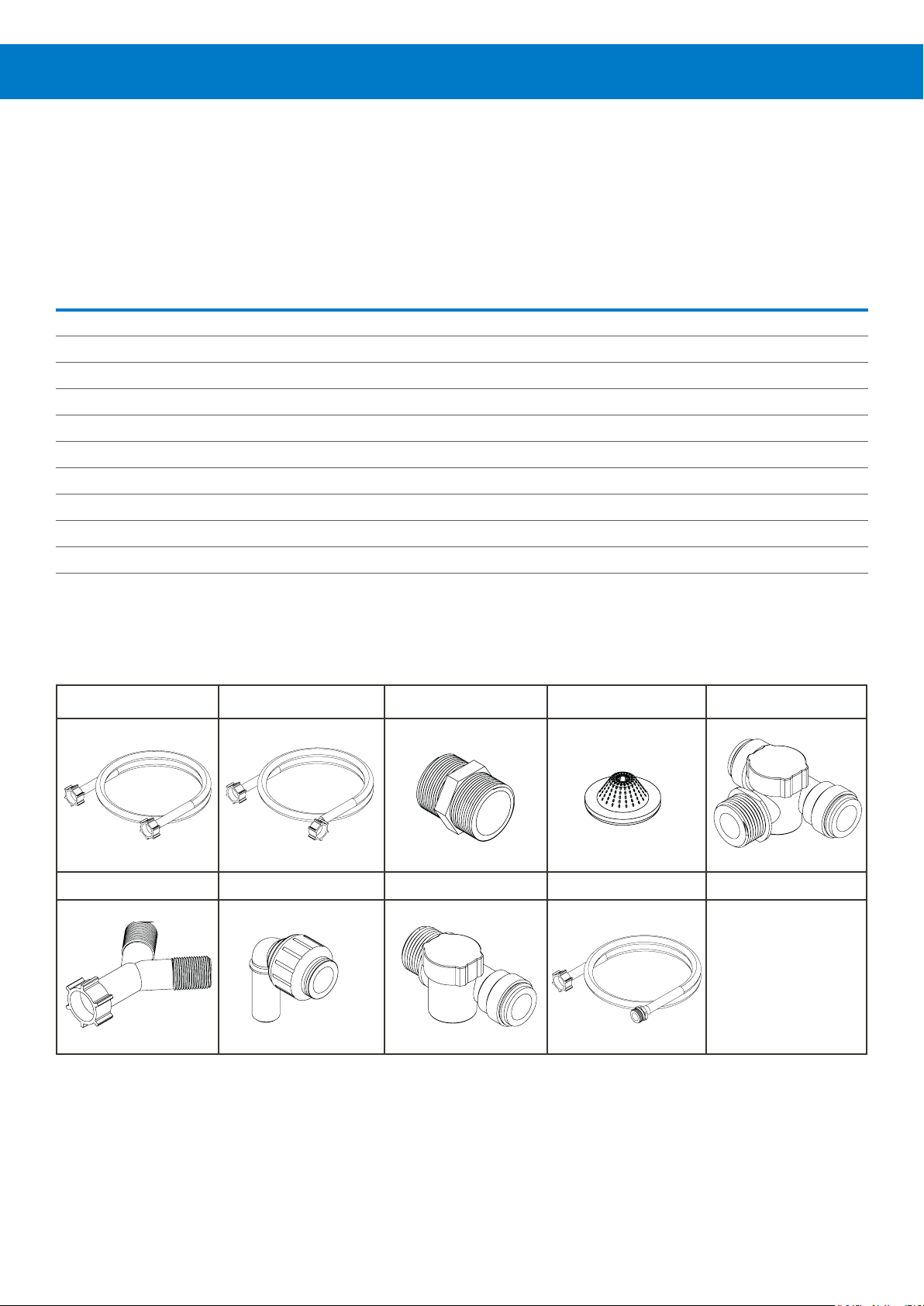
10. spares & accessories
Install kits
Install kits are available for both 115V and 230V versions, reference the table below against the part images:
Install kit for X number of EvoClean Dispensers
230v BSP Version 115v GH Version
Description
1 ¾ BSP Water Hose, Straight 1x 1x 2x - - -
2 ¾ BSP Water Hose, 90° Elbow 1x 2x 3x - - -
3 ¾ BSP Nipple 1x 2x 3x - - -
4 Strainer Washer 1x 1x 1x 1x 1x 1x
5 ¾ BSP x 15mm, Tee, Valve 1x 1x 3x - - -
6 ¾ BSP, Y-Piece Adaptor - 1x - - - -
7 15mm, Adaptor Elbow - - 2x - - -
8 ¾ BSP x 15mm, Straight, Valve - - 2x - - -
9 Hose, 3-8 ID - - - 2x 3x 5x
10 Brass Y-Piece Adaptor
1 2 3 4 5
1x EvoClean 2x EvoClean 3x EvoClean 1x EvoClean 2x EvoClean 3x EvoClean
HYD10099195 HYD10099196 HYD10099197 HYD10099188 HYD10099189 HYD10099190
- - - 1x 2x 3x
6 & 10 7 8 9
HYD10099044 Rev 1.4
Page 17 Hydro Systems Co. 2019
Page 18
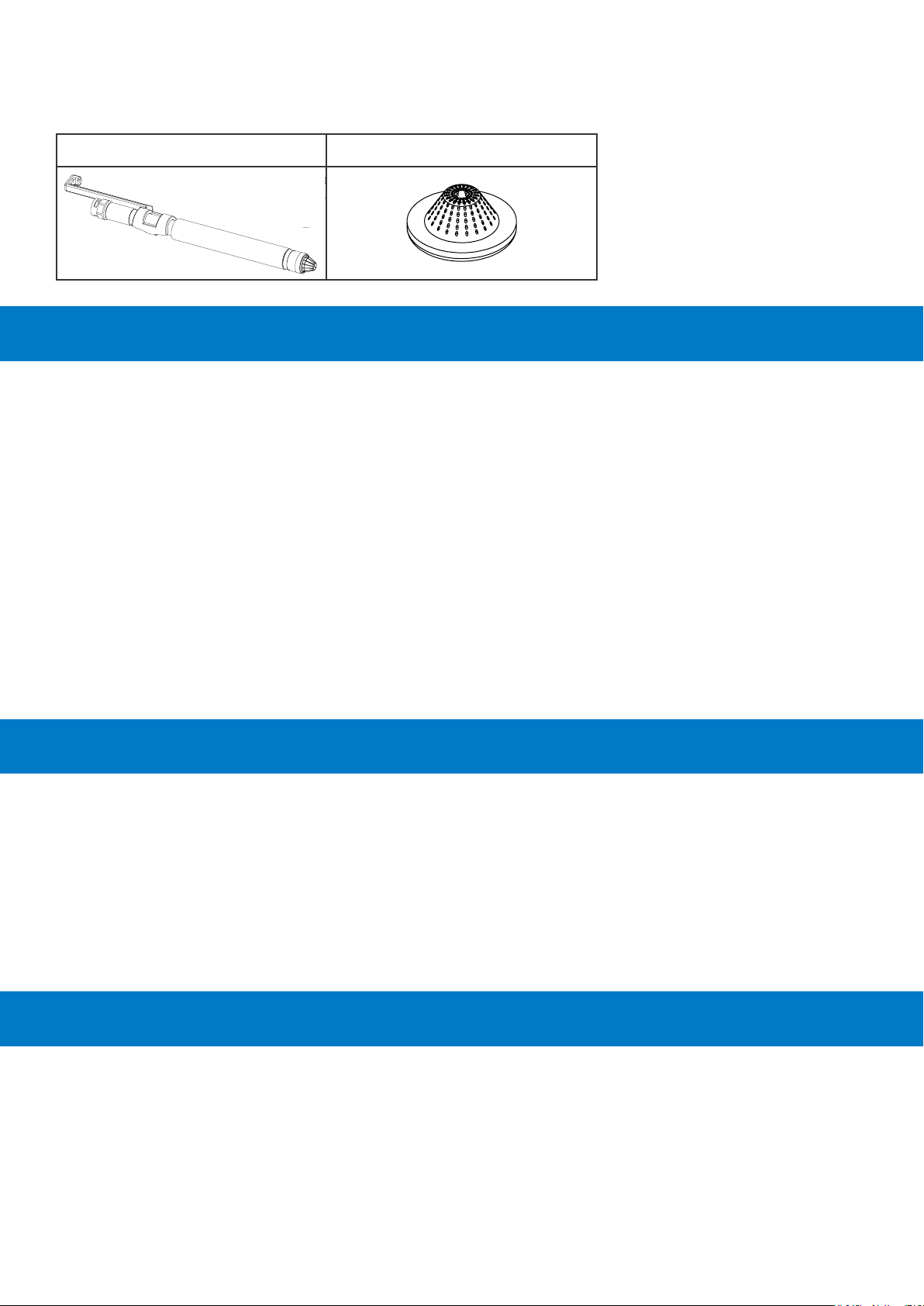
Maintenance kit
The following maintenance kit is available, which allows the correct maintenance regime to be followed as detailed in this
manual:
1x pickup tube assembly 1x washer strainer
11. warranty
Seller warrants solely to Buyer the Products will be free from defects in material and workmanship under normal use and
service for a period of one year from the date of completion of manufacture. This limited warranty does not apply to (a)
hoses; (b) and products that have a normal life shorter than one year; or (c) failure in performance or damage caused by
chemicals, abrasive materials, corrosion, lightning, improper voltage supply, physical abuse, mishandling or misapplication.
In the event the Products are altered or repaired by Buyer without Seller’s prior written approval, all warranties will be void.
No other warranty, oral, express or implied, including any warranty of merchantability or fitness for any particular
purpose, is made for these products, and all other warranties are hereby expressly excluded.
Seller’s sole obligation under this warranty will be, at Seller’s option, to repair or replace F.O.B. Seller’s facility in Cincinnati,
Ohio or Bracknell, England any Products found to be other than as warranted.
Limitation of Liability
Seller’s warranty obligations and Buyer’s remedies are solely and exclusively as stated herein. Seller shall have no other
liability, direct or indirect, of any kind, including liability for special, incidental, or consequential damages or for any other
claims for damage or loss resulting from any cause whatsoever, whether based on negligence, strict liability, breach of
contract or breach of warranty.
12. decommissioning and disposal
Hydro products are manufactured from materials which can be recycled. Dispose of Hydro products in accordance with the
current local regulations.
• All electrical connections have been removed and
disposed of according to local regulations
• Any hazard Warning signs have been removed or
totally defaced
• Safe for disposal sign attached appropriately to each
of the listed items.
• The items have been left in a condition such that it is
safe for lay personnel or contractor to remove it without
need for precautions against exposure to any electrical
supply or other agents.
13. electrical approvals
Compliance to standards and test data / EC declaration of conformity
This EvoBoost complies with the following EU directives;
2014/35/EU Conforms with the safety objectives of the low voltage directive and its amending
directives.
2014/30/EU Conforms with the essential requirements of the electromagnetic compatibility directive
and its amending directives.
Page 18 Hydro Systems Co. 2019HYD10099044 Rev 1.4
Page 19

14. Water Approvals
Hydro Systems EvoBoost has certified UK WRAS Approval. Certificate Number: 1908742
This product has been tested and found to comply with the requirements of the Water Supply (Water Fittings) Regulations
1999 for England and Wales, theWater Byelaws 2014, Scotland and the Water Regulations Nothern Ireland.
This product is certified as suitable for backflow prevention against fluid category 4, with a maximum working pressure 6.0
bar and has been certified for cold water use only.
15. WEEE - Waste Electrical and Electronic Equipment
WEEE Regulations apply to companies who Manufacture & Distribute electrical or electronic equipment. (EEE)
The WEEE Regulations apply to importers, producers, retailers and users of EEE, and to businesses that treat or recover
WEEE. The Low Level Alarm unit is a product placed onto market POST 13.08.05 , therefore called ‘future WEEE’. As a
producer Hydro Systems Europe have the option to take responsibility for the EEE placed on the market. If Hydro Systems
Europe chooses to receive WEEE they must make sure that it is disposed of in an environmentally sound way, including the
treatment, reuse, recovery and recycling of the components where appropriate.
Responsibility as a producer of EEE
Hydro Systems Europe, as a producer of EEE, are registered with a producer compliance scheme who register them with
the relevant environmental regulator.
Through the regulator they become part of an approved producer compliance scheme (PCS).The PCS supply a unique and
permanent producer registration number.
If disposal is outsourced it (the product) must be taken to an appropriately licensed site (approved authorised treatment
facility - AATF) where it can be treated safely.
HYD10099044 Rev 1.4
Page 19 Hydro Systems Co. 2019
Page 20

Hydro Systems Company
Americas +1 513-271-88OO [email protected] www.hydrosystemsco.com
Europe +44 O1344 48888O [email protected] www.hydrosystemseurope.com
Asia Pacific +86 21-6187-1O3O [email protected] www.hydrosystemschina.com
 Loading...