


November 15, 2019
Lit. No. 74033, Rev. 01
29049, 29051, 29053, 29400-7
HARNESS KIT
3-PORT ISOLATION MODULE
LIGHT SYSTEM
w/2-PLUG SYSTEM HARNESSES
Parts List and Installation Instructions
CAUTION
Read this document before installing the
snowplow.
CAUTION
See your sales outlet/website for specifi c
vehicle application recommendations before
installation. The online selection system has
specifi c vehicle and snowplow requirements.
A DIVISION OF DOUGL AS DYNAMICS, LLC

29049, 29051, 29053, 29400-7
PARTS LIST
Plug-In Harness Kit and Plug-In Harness Extension
Qty
Part Description
28986 Plug-In Harness, H13 1
28464 Plug-In Harness, 2B or 2D or HB-2 1
29058 Plug-In Harness, 5-Pin Connector 1
29499 -1 Plug-In Harness, HB-3 & H11 1
26357 Vehicle Lighting Harness – 11-Pin 1 1
40284 Isolated Stud Block 1
21563 Battery Cable – 90" 1
29861-4
29071 8" Cable Assembly 1
95837 Fuse Holder 1
90729 200A Fuse 1
Vehicle Lighting Harness – 11-Pin w/Relay
Assembly
– Reclosable Fasteners 4 4 4 4
– Splices 1111
– Heatshrink Tubing 1111
29049
29051
29053
11
LED Plow Light Kit
Part Description Qty
72565 Headlamp Control Module (HCM) 1
72554 Harness Assembly – HCM to Isolation Module 1
72546 Vehicle Harness Assembly – HCM to Grille 1
72548 Harness Assembly – Plow Lighting 1
72550 Cable Assembly – HCM 1
72552 Wire Assembly – EdgeView™ Lights 1
– Reclosable Fasteners 4
29400-7
90730
Lit. No. 74033, Rev. 01 2 November 15, 2019

29049, 29051, 29053, 29400-7
SAFETY DEFINITIONS
WARNING
Indicates a potentially hazardous situation
that, if not avoided, could result in death or
serious personal injury.
CAUTION
Indicates a potentially hazardous situation
that, if not avoided, may result in minor or
moderate injury. It may also be used to alert
against unsafe practices.
NOTE: Indicates a situation or action that can lead
to damage to your snowplow and vehicle or other
property. Other useful information can also be
described.
FUSES
The snowplow electrical and hydraulic systems
contain several automotive-style fuses. If a problem
should occur and fuse replacement is necessary,
the replacement fuse must be of the same type and
amperage rating as the original. Installing a fuse with
a higher rating can damage the system and could start
a fi re. Fuse Replacement, including fuse ratings and
locations, is located in the Maintenance section of the
Owner's Manual.
BATTERY SAFETY
CAUTION
Batteries normally produce explosive gases,
which can cause personal injury. Therefore,
do not allow fl ames, sparks, or lit tobacco
to come near the battery. When charging or
working near a battery, always cover your
face and protect your eyes, and also provide
ventilation.
• Batteries contain sulfuric acid, which burns
skin, eyes, and clothing.
• Disconnect the battery before removing or
replacing any electrical components.
TORQUE CHART
CAUTION
Read instructions before assembling.
Fasteners should be fi nger tight until
instructed to tighten according to the torque
chart. Use standard methods and practices
when attaching snowplow, including proper
personal protective safety equipment.
Recommended Fastener Torque Chart
Inch Fasteners Grade 5 and Grade 8
Size Size
1/4-20 148 209
1/4-28 164 232
5/16-18 203 287
5/16-24 230 325
3/8-16 365 510
3/8-24
7/16 -14
7/16 -20
1/2-13
1/2-20
Tor qu e ( N·m)
Grade
5
11. 4
13.1
23.6
26.0
41.8
47.5
67.0
74. 8
102.1
115 .2
Grade
16.2
18.5
33.3
36.9
59.1
67.0
94.6
105.6
144.3
162.7
8
9/16-12
9/16-18
5/8-11
5/8-18
3/4-10
3/4-16
7/8 -9
7/8 -14 643 907
1-12 954 1349
Metric Fasteners Class 8.8 and 10.9
Size Size
M6 x 1.00
M8 x 1.25
M10 x 1.50
M12 x 1.75
M14 x 2.00
M16 x 2.00
M18 x 2.50 431301
Tor qu e ( N·m)
Class
8.8
10.4
26.4
52.2
91
145
226
These torque values apply to fasteners
except those noted in the instructions.
36.5
72.2
126
200
313
Class
10.9
M20 x 2.5015.0
M22 x 2.50
M24 x 3.00
M27 x 3.00
M30 x 3.50
M33 x 3.50
M36 x 4.00
Tor qu e ( N·m)
Grade
5
403 569
582 822
873 12321-8
Tor qu e ( N·m)
Class
8.8
441
580
762
1079
1515
1990
2647
Grade
8
Class
10.9
610
831
1055
154 4
2095
2849
3662
Lit. No. 74033, Rev. 01 3 November 15, 2019

29049, 29051, 29053, 29400-7
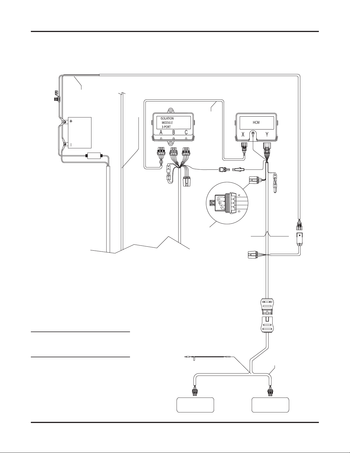
TYPICAL 2-PLUG, 3-PORT MODULE SYSTEM DIAGRAM
NOTE: On 2-plug electrical systems, plug covers
shall be used whenever snowplow is disconnected.
To Switched
Accessory
To Snowplow Control
RED
200A Fuse
and Holder**
Fire Wall
8" Cable**
RED
Battery*
* See the Battery Connections section
for more information.
** Included in 200A Fuse Kit (PN 90730).
BLK
Vehicle Control Harness
3-Port Module
10A Fuses
snowplow control)
(snowplow park/turn &
Turn Signal
Configuration Plug
BAT
(11-pin)
Vehicle Lighting
Harness
Typical Plug-In Harness
Factory Vehicle Harness
Vehicle Battery Cable
Factory Vehicle Harness
Park/Turn
Park/Turn
Lamps
Vehicle
Vehicle
Headlamps
Lit. No. 74033, Rev. 01 4 November 15, 2019
Headlamps
Lamps

29049, 29051, 29053, 29400-7
INSTALLATION INSTRUCTIONS
Isolation Module Mounting
CAUTION
Before installing self-drilling screws or
drilling mounting holes, check the selected
mounting area for any wires, hoses, or other
obstructions.
Isolation modules are sold separately. Check the
online selection system for the correct module for your
vehicle.
Locate a fl at surface within the engine compartment of
the vehicle for mounting the isolation module (on the
driver's side, if possible). The fi re wall, fender well,
or radiator shroud are possible mounting locations. If
a suitable fl at surface is not accessible, cable tie the
isolation module to existing brackets or harnessing.
Reclosable fastener strips and/or cable ties are
supplied for mounting the isolation module, but
self-drilling screws can also be used. When using
reclosable fastener strips, the mounting surface must
be free of dirt and grease.
Isolation Module
(bottom view)
Reclosable
Fastener
Strips
Screws (2)
Cable
Ties (4)
(if supplied)
Vehicle Battery Cable Installation
CAUTION
Batteries normally produce explosive gases,
which can cause personal injury. Therefore,
do not allow fl ames, sparks, or lit tobacco
to come near the battery. When charging or
working near a battery, always cover your
face and protect your eyes, and also provide
ventilation.
• Batteries contain sulfuric acid, which burns
skin, eyes, and clothing.
• Disconnect the battery before removing or
replacing any electrical components.
NOTE: Fuse holder and fuse are to be installed
between the POSITIVE (+) vehicle battery terminal
and the end of the supplied snowplow vehicle
battery cable assembly.
NOTE: When instructed, make all snowplow
battery cable connections to the auxiliary battery,
if vehicle is so equipped.
NOTE: Use dielectric grease on all electrical
connections to prevent corrosion. Fill receptacles
and lightly coat ring terminals before assembly.
NOTE: For vehicles equipped with a tilt cab
or tilt hood, a service loop will be necessary
when making harness or cable transitions from
the cab/hood to the frame. Check the cable
installation for interference by raising and
lowering the cab/hood a number of times. Add
anti-chafi ng material (installer-supplied) as
needed.
1. Turn OFF the vehicle ignition.
2. Disconnect both the NEGATIVE (–) and the
POSITIVE (+) battery cables from the vehicle
battery.
Lit. No. 74033, Rev. 01 5 November 15, 2019

29049, 29051, 29053, 29400-7
3. Route the supplied vehicle battery cable from
the grille or bumper to the battery, avoiding any
sharp edges and hot or moving parts. Cable tie
only the end section closest to the grille. The
vehicle battery cable may need to be lengthened
on vehicles with batteries located under or behind
the cab.
If lengthening cables is necessary, use the
supplied isolated stud junction block. Mount the
block to a fl at surface within reach of the vehicle
battery cable, and connect both the vehicle
battery cable and the supplied 90" battery cable to
the junction block.
Vehicle
Battery Cable
90" Battery Cable
Isolated Stud
Junction Block
4. Remove the fuse holder cover, loosen and remove
the fuse holder nuts and lock washers. Install a
200A fuse into the fuse holder.
5. Attach one end of the supplied 8" cable to the
fuse holder so that the ring terminal is on top of
the fuse. Replace the lock washer and nut on this
terminal and hand tighten the nut.
6. Attach the red lead from the vehicle battery cable
(or 90" battery cable) to the second fuse holder
terminal, placing the cable ring terminal on top of
the fuse lead. Replace the lock washer and nut on
this terminal and hand tighten the nut.
7. Torque the fuse holder nuts to 106–159 in-lb and
snap the fuse holder cover into place.
8. Route the 8" cable from the fuse holder to the
POSITIVE (+) battery terminal. Do not connect at
this time.
9. Route the black wire from the vehicle battery cable
to the NEGATIVE (–) battery connection point.
Do not connect at this time. On vehicles with the
batteries located under or behind the cab, connect
the black wire from the vehicle battery cable to
the frame using an existing hole or ground bolt.
Prior to attaching, clean away any paint or dirt to
ensure a good ground connection. The 4-position
connector from the vehicle battery cable will
connect to the mating connector (labeled "BAT")
on the end of the vehicle control harness.
* For installations requiring an adapter, follow the instructions included with the adapter.
Lit. No. 74033, Rev. 01 6 November 15, 2019

29049, 29051, 29053, 29400-7
Vehicle Lighting and Vehicle Control
Harness Installation
For Halogen plow light installation, proceed with
the following instructions.
For LED plow light installation, install the vehicle
control harness as instructed, but DO NOT install
the supplied vehicle lighting harness. Instead,
refer to the LED Installation Instructions on
page 10.
NOTE: For vehicles equipped with a tilt cab
or tilt hood, a service loop will be necessary
when making harness or cable transitions from
the cab/hood to the frame. Check the cable
installation for interference by raising and
lowering the cab/hood a number of times. Add
anti-chafi ng material (installer-supplied) as
needed.
1. Route both harnesses around or through the
radiator bulkhead to the isolation module.
2. Connect the vehicle lighting harness to
position "A" on the 3-port isolation module.
3. Route the end of the vehicle control harness with
the white 4-pin connector to the fi re wall.
4. Connect the black 4-position connector (labeled
"BAT") from the end of the vehicle control harness
to the 4-position connector from the vehicle
battery cable. Do not cable tie the harness at
this time.
CAUTION
Before installing self-drilling screws or
drilling mounting holes, check the selected
mounting area for any wires, hoses, or other
obstructions.
5. On the driver's side, locate an existing hole
through the fi re wall for the vehicle control
harness. If access through the fi re wall does not
exist, drill a 5/8" hole through the fi re wall of the
vehicle in a convenient location away from sharp
edges and hot or moving parts.
6. Push the braided harness breakout with the cab
control connector through the fi re wall hole into the
cab. Use a grommet, existing plug cover, or proper
chafi ng material to protect the harness where it
passes through the fi re wall. Route the harness to
the selected control mounting location.
To mount the control, follow the instructions
supplied with the control.
7. Locate an accessory wire controlled by the ignition
switch. Acceptable accessory wires show +12V
when the ignition switch is ON, and 0V when it
is OFF.
8. Route the red "ACC" wire from the vehicle control
harness to this location and trim away excess
length.
9. Following the instructions in the Recommended
Splicing Procedure section, splice the red
"ACC" wire into the switched accessory wire using
the supplied parallel splices and heatshrink tubing.
NOTE: Cable tie the control harness and
accessory tap away from the brake, clutch, gas,
or parking brake pedals, and any hot, sharp, or
moving parts.
Lit. No. 74033, Rev. 01 7 November 15, 2019

29049, 29051, 29053, 29400-7
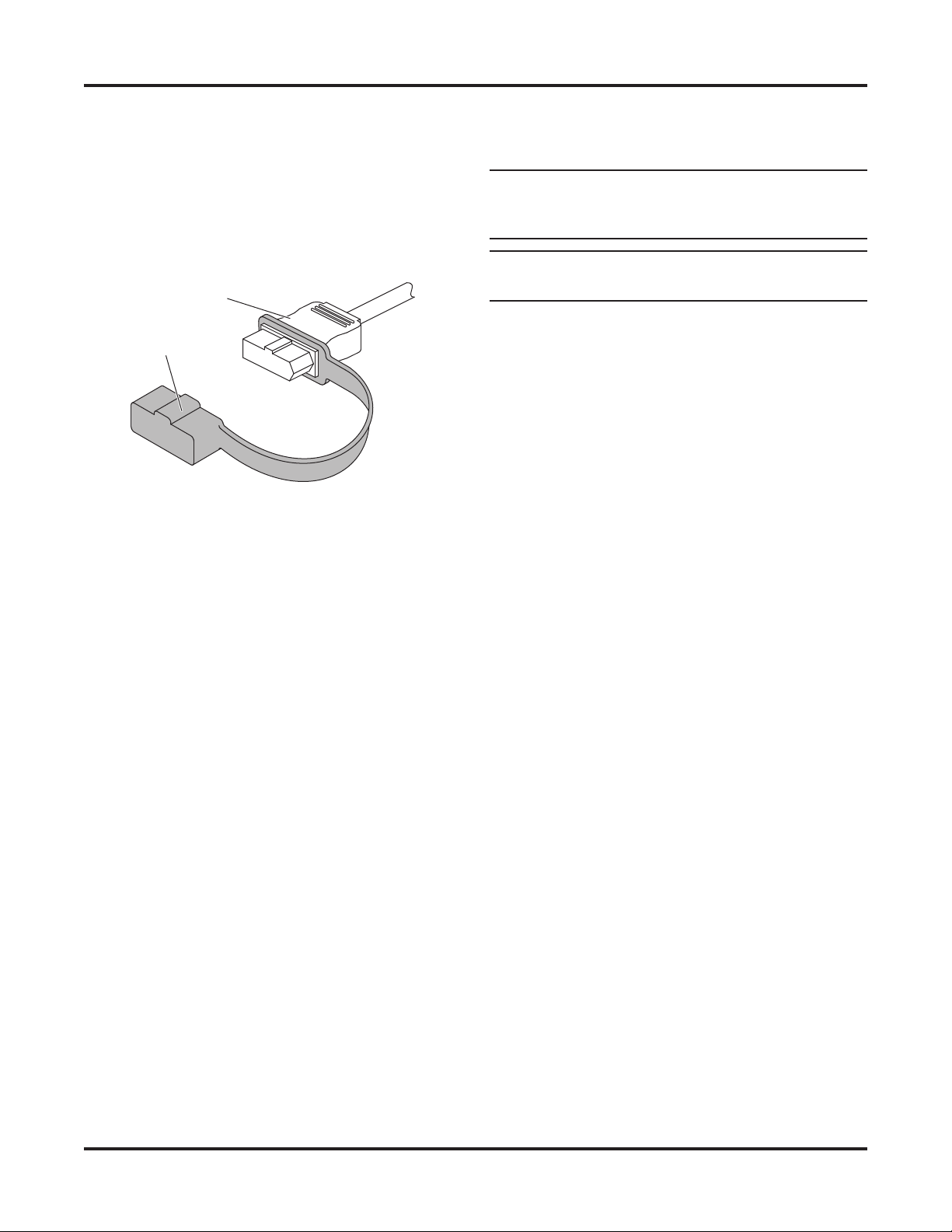
PLUG COVER INSTALLATION
Stretch the rectangular opening of the plug cover
strap over the end of the vehicle battery cable. Place
the plug cover over the molded plug whenever the
snowplow is not in use.
Molded Plug
Plug Cover
PLUG-IN HARNESS INSTALLATION:
VEHICLES USING THE 29053 HARNESS
KIT
1. Locate the passenger-side OEM vehicle headlamp
connector located near the tilt-hood hinge below
the headlamp housing.
2. Remove the small, light gray connector lock by
carefully sliding it back away from the connector.
Save the connector lock. Separate the connectors
by pushing down on the locking tab and pulling
them apart.
3. Connect the plug-in harness female connector
to the male OEM vehicle headlamp connector.
Reinstall the small, light gray connector lock.
4. Connect the plug-in harness male connector to
the female OEM vehicle headlamp connector.
5. Route the remaining half of the plug-in harness to
the driver-side OEM vehicle headlamp connector,
and repeat Steps 2–4.
6. Route the plug-in harness to the 3-port isolation
module by running the harness along the existing
cables underneath the engine and radiator area.
Connect the plug-in harness to the module by
matching harness connector B with module port B
and harness connector C with module port C.
7. Connect the black 4-position connector from
the middle of the vehicle control harness to the
4-position connector from the plug-in harness.
8. Cable tie the vehicle control harness, vehicle
lighting harness, and plug-in harness away from
any sharp, hot, or moving parts.
9. Skip ahead to the Turn Signal Confi guration Plug
section.
Lit. No. 74033, Rev. 01 8 November 15, 2019

29049, 29051, 29053, 29400-7
PLUG-IN HARNESS INSTALLATION:
ALL OTHER APPLICATIONS
NOTE: For vehicles equipped with a tilt cab or
tilt hood, a service loop will be necessary when
making harness or cable transitions from the
cab/hood to the frame. Check the cable installation
for interference by raising and lowering the
cab/hood a number of times. Add anti-chafi ng
material (installer-supplied) as needed.
1. For vehicles using the 29400-7 harness kit:
The plug-in harness contains four reversible
2-position connectors. One set of connectors
connects to the HB-3 bulbs and one set connects
with the H11 bulbs.
NOTE: To properly install reversible 2-position
connectors, it is necessary to know which pin of
the OEM headlamp connectors is common.* When
mating the OEM headlamp connectors with the
plug-in harness, be sure to orient the connectors
as shown below.
A (Common)
B
OEM Headlamp Connector**
A
B (Common)
OEM Headlamp Connector** Plug-In Harness Connector**
** Connector appearance will vary.
NOTE: DO NOT PROBE OR DAMAGE THE WIRE
INSULATION. When the common wire is located
the test lamp will illuminate.
Plug-In Harness Connector**
2. Remove the headlamp or headlamp housing
connectors. Connect the plug-in harness to the
mating connectors removed from the headlamps
or headlamp housings.* Connect the plug-in
harness to the mating connections at the
headlamps or headlamp housings. Route the
plug-in harness to the 3-port isolation module.
Connect the plug-in harness to the module by
matching harness connector B with module port B
and harness connector C with module port C.
For vehicles with dedicated Daytime Running
Light (DRL) bulbs: Connect the DRL wire from
the plug-in harness to the vehicle DRL bulb
POSITIVE (+) wire.
For vehicles with headlamp bulb or turn signal
DRLs: The DRL wire from the plug-in harness will
not be used. Coil and cable tie the DRL wire.
For vehicles requiring the 69826, 69826-1, or
69826-2 relay adapter kit, refer to the Installation
Instructions packed with the kit.
3. Connect the black 4-position connector from
the middle of the vehicle control harness to the
4-position connector from the plug-in harness.
4. If not already done during adapter installation,
locate the turn signal wire on each side of
the vehicle. Splice the "TURN" wire from the
plug-in harness into the signal wire on the
corresponding side following the instructions in the
Recommended Splicing Procedure section.
5. If not already done during adapter installation,
splice the "PARK" wire from the plug-in harness
into the parking light wire following the instructions
in the Recommended Splicing Procedure section.
6. Cable tie the vehicle control harness, vehicle
lighting harness, and plug-in harness away from
any sharp, hot, or moving parts.
7. For vehicles using the 29400-7 harness kit:
To complete the installation, secure the relay
assemblies to an existing assembly using cable
ties. Mount the relay connectors wire side down.
* See A & B markings on the OEM headlamp connector for pin identifi cation when testing for common.
Lit. No. 74033, Rev. 01 9 November 15, 2019

29049, 29051, 29053, 29400-7
TURN SIGNAL CONFIGURATION PLUG
WARNING
If the turn signal confi guration plug is mated
incorrectly, the turn signals will be reversed
between the vehicle and the snowplow.
1. Mate the turn signal confi guration plug located
on the plug-in harness. If the isolation module is
installed on the driver's side, mate the plug so that
the wire colors match (green to green and blue to
blue). If the module is installed on the passenger's
side, mate the plug so that the wire colors are
opposite (green to blue).
Turn Signal Configuration Plug
LED INSTALLATION INSTRUCTIONS
Headlamp Control Module (HCM)
Mounting
Locate a fl at surface within the engine compartment
of the vehicle near the isolation module. If a suitable
fl at surface is not accessible, cable tie the HCM to
existing brackets or harnessing.
Mount the HCM so that the harness connections are
wire side down.
NOTE: If possible, mount the HCM in an area that
is protected from road splash.
Reclosable fastener strips and/or cable ties are
supplied for mounting the HCM. When using
reclosable fastener strips, the mounting surface must
be free of dirt and grease.
Headlamp Control Module
(bottom view)
B – Green & Red Wires C – Blue & Red Wires
Driver-Side Module Passenger-Side Module
GRN GRN
BLU BLU
2. Connect the single-wire connector from the
vehicle lighting harness to the single-wire
connector from the plug-in harness.
BLU GRN
GRN BLU
Reclosable
Fastener
Strips
Cable
Ties (4)
Lit. No. 74033, Rev. 01 10 November 15, 2019

29049, 29051, 29053, 29400-7
HCM Vehicle Battery Cable Installation
CAUTION
Batteries normally produce explosive gases,
which can cause personal injury. Therefore,
do not allow fl ames, sparks, or lit tobacco
to come near the battery. When charging or
working near a battery, always cover your
face and protect your eyes, and also provide
ventilation.
• Batteries contain sulfuric acid, which burns
skin, eyes, and clothing.
• Disconnect the battery before removing or
replacing any electrical components.
NOTE: When instructed, make all snowplow
battery cable connections to the auxiliary battery,
if vehicle is so equipped.
NOTE: Use dielectric grease on all electrical
connections to prevent corrosion. Fill receptacles
and lightly coat ring terminals before assembly.
1. Turn OFF the vehicle ignition.
HCM Vehicle Lighting Harness Installation
1. Route harnesses around or through the radiator
bulkhead to the HCM.
2. Make the following connections:
• 2-position connector from the vehicle lighting
harness to the matching 2-position connector from
the vehicle cable assembly
• Vehicle lighting harness to position "Y" on the
HCM
• Single-pin connector from the plug-in harness
assembly to the single-pin connector on the
vehicle lighting harness.
3. Route the red wire from the vehicle lighting
harness to the stud on the HCM.
4. Remove the protective plastic domed nut and the
top brass nut from the HCM stud. Install the red
wire ring terminal on stud and remaining brass
nut. Reinstall the top brass nut and tighten to
25.9 in-lb. Reinstall the protective plastic domed
nut. (See illustration below.)
2. Disconnect both the NEGATIVE (–) and the
POSITIVE (+) battery cables from the vehicle
battery.
3. Route the supplied HCM vehicle battery cable
from the battery to the 2-position mating connector
on the HCM vehicle lighting harness, avoiding any
sharp edges and hot or moving parts.
Brass Nuts
Domed Nut
Headlamp Control Module (HCM)
Red Wire Ring Terminal
(from vehicle lighting harness)
Lit. No. 74033, Rev. 01 11 November 15, 2019
29049, 29051, 29053, 29400-7
TYPICAL LED PLOW LIGHT, HEADLAMP CONTROL MODULE (HCM),
AND HARNESS DIAGRAM
To Snowplow Control
25A Fuse
Vehicle
Cable
Assembly
Battery
200A Fuse
and Holder*
Vehicle Control Harness
Vehicle Battery Cable
* Included in 200A Fuse Kit (PN 90730).
Accessory
To Switched
HCM to
Isolation Module
Harness Assembly
Plug
Turn Signal
Configuration
10A Fuses
EdgeView
Enable Jumper
Install with
wires down.
RED
EdgeView
Wire
15A Fuses
Ford SD Quad Light
Relay Enable Plug & Cover
RAM Enable
Wire (7-wire
system only)
ORN YEL
Vehicle
Lighting
Harness
NOTE: On 2-plug electrical systems,
plug covers shall be used whenever
EdgeView™
snowplow is disconnected.
Lit. No. 74033, Rev. 01 12 November 15, 2019
Wire Assembly
Plow
YEL
Plow Lights
Lighting Harness
29049, 29051, 29053, 29400-7
PLUG COVER INSTALLATION
Stretch the rectangular opening of the plug cover strap
over the end of the HCM vehicle lighting harness.
Place the plug cover over the molded plug whenever
the snowplow is not in use.
Molded Plug
Plug Cover
HCM TO ISOLATION MODULE HARNESS
INSTALLATION
1. Make the following connections:
• 10-pin connector to port A of the isolation module
• 8-position connector to port X of the HCM.
BATTERY CONNECTIONS
NOTE: Use cable ties to secure cable assemblies
and control and lighting harnesses away from any
sharp edges and hot or moving parts.
NOTE: Follow OEM battery cable connection
recommendations when attaching to the battery.
1. Make the following attachments to the
POSITIVE (+) battery terminal:
• POSITIVE (+) OEM cable assembly
• Red 8" cable from fuse holder
• Red cable from headlamp control module power
cable.
2. Make the following attachments to the
NEGATIVE (–) battery terminal:
• NEGATIVE (–) OEM cable assembly
• Black vehicle battery cable
• Black cable from headlamp control module power
cable.
2. Cable tie harnesses as needed, away from any
sharp, hot, or moving parts.
Lit. No. 74033, Rev. 01 13 November 15, 2019

29049, 29051, 29053, 29400-7
BATTERY CABLE CONNECTIONS
Top Post Batteries w/Lead Cable Ends
1. Attach the POSITIVE (+) OEM cable to the battery
post. Attach the red battery cable to the bolt in the
OEM terminal with original fastener.
2. Attach the NEGATIVE (–) OEM cable to the battery
post. Attach the black wire from the vehicle battery
cable to the OEM terminal bolt with original fastener.
Top Post Batteries w/Stamped Steel
Battery Terminals
Top Post Batteries, Style One
These terminals are secured with a 6 mm washer-head
cap screw and nut. If the cap screw is already long
enough for the added thickness of the cable terminal,
washer, and nut, it will not need to be replaced, and
Step 1 may be skipped.
1. Carefully lift retainer tabs (if present) and remove the
short cap screw. Insert the supplied longer cap screw
through a 3/16" washer and into the hole in the clamp.
Carefully bend the retainer tabs back into place.
Red Battery Cable
Top Post Batteries, Style Two
These terminals are secured with a 6 mm tapered nut
and cam.
1. Make the connections to the POSITIVE (+)
terminal as follows:
a. Remove the cable assembly from the battery
post by loosening the nut. Trim the plastic
terminal cover as shown.
Trim ma rked are as.
Nut
Cam
Tab
Washer
(See Step 3.)
Battery
Clamp
2. Attach the POSITIVE (+) OEM battery clamp to
the battery post, and secure the clamp.
3. Place the red battery cable over the end of the
battery terminal screw. If the added terminal has
large contact area with the battery clamp, retain
with washer and nut. If the terminal contact area
is small (terminal hole almost passes over a 6 mm
nut), add a washer on both sides of the cable and
secure with a nut.
4. Connect the black wire from the vehicle battery
cable and the OEM NEGATIVE (–) cable to the
NEGATIVE (–) battery terminal following the same
procedure used in Steps 1–3.
Vehicle Cable
Cap Screws
(See Step 1.)
b. Carefully bend the tab securing the cam
upward so that the cam can be lifted off the
stamped terminal after the nut has been
removed.
c. Place the red battery cable over the battery
terminal screw.
d. Slide the cam over the terminal screw and tab.
Reinstall the nut.
e. Place the cable assembly on the battery post,
align the red battery cable with the opening
in the cover, and tighten the nut. Close the
plastic terminal cover.
Lit. No. 74033, Rev. 01 14 November 15, 2019

29049, 29051, 29053, 29400-7
2. Make the connections to the NEGATIVE (–)
terminal as follows:
a. Remove the cable assembly from the battery
post by loosening the nut.
b. Carefully bend the tab securing the cam
upward so that the cam can be lifted off the
stamped terminal after the nut has been
removed.
c. Place the black wire from the vehicle battery
cable over the battery terminal screw.
d. Slide the cam over the terminal screw and tab.
Reinstall the nut.
e. Place the cable assembly on the battery post,
and tighten the nut.
Top Post Batteries, Style Three
These terminals are similar to Style Two, but do not
have a visible cam or tab.
2. Make the connections to the NEGATIVE (–)
terminal as follows:
a. Remove the cable assembly from the battery
post by removing the nut.
b. Place the black wire from the vehicle battery
cable over the battery terminal screw and
reinstall the nut.
c. Place the cable assembly on the battery post,
and tighten the nut.
Side Terminal Batteries
1. Use the furnished battery cable adapter to attach
the red battery cable to the POSITIVE (+) terminal
of the battery. Position the cable, and tighten the
adapter to 124–178 in-lb.
2. Connect the OEM POSITIVE (+) cable to the
adapter on the battery. Position the cable and,
while holding the adapter, tighten the battery cable
bolt to 124–178 in-lb.
1. Make the connections to the POSITIVE (+)
terminal as follows:
a. Remove the cable assembly from the battery
post by removing the nut. Trim the plastic
terminal cover as necessary to accommodate
the red snowplow battery cable.
b. Place the red battery cable over the battery
terminal screw and reinstall the nut.
c. Place the cable assembly on the battery post,
align the red battery cable with the opening
in the cover, and tighten the nut. Close the
plastic terminal cover.
3. Connect the black wire from the vehicle battery
cable and the OEM NEGATIVE (–) cable to the
NEGATIVE (–) battery terminal following the same
procedure used in Steps 1 and 2.
Lit. No. 74033, Rev. 01 15 November 15, 2019

29049, 29051, 29053, 29400-7
CHANGING BLADE-EDGE
ILLUMINATION MODE
On snowplows equipped with LED headlamps, the
EdgeView™ technology feature off ers three modes for
blade-edge illumination. The factory default setting is
ON.
To change the blade-edge illumination mode, remove
the cover from the fuse holder located near the
"Y" port of the headlamp control module installed in
the vehicle engine compartment.
HEADLAMP
CONTROL MODULE
Fuse Holder
and Cover
Headlamp
Control Module
Remove the jumper fuse from the fuse holder and
re-insert it in the desired mode position as shown
below. Replace the fuse holder cover.
Jumper
Fuse
Default – ON:
Blade edge lights
illuminate when
plow has power.
FLT: Blade edge
lights illuminate
when blade is in
FLOAT mode.
PLOW-SIDE EdgeView LIGHTING
CONNECTIONS
The EdgeView Float (FLT) mode activation function
will require a second plow-side electrical connection.
1. On the plow-side LED lighting harness, locate the
yellow wire cable tied to the body of the harness
near the "Y" section.
2. Strip the end of the yellow wire and insert
stripped wire end into the pre-installed insulated
butt connector on the supplied EdgeView wire
assembly.
3. Crimp the connection and heat seal the insulated
splice.
4. Remove the snowplow hydraulic unit cover. Route
the EdgeView wire assembly along the snowplow
structure to the snowplow hydraulic unit, and cable
tie wires as needed.
5. Locate the solenoid on the snowplow hydraulic
unit that is activated during the snowplow
Lower/Float function. Refer to the Mechanic's
Guide or snowplow manufacturer's website for
further information.
6. Plug the bullet terminal on the end of the supplied
EdgeView wire assembly into the receptacle on
the corresponding solenoid wire. If a receptacle is
not found on the correct solenoid wire, remove the
bullet terminal from the EdgeView wire assembly
and splice the end of the EdgeView wire into the
correct solenoid wire.
7. Cable tie extra wire length to the snowplow
assembly and reinstall the hydraulic unit covers.
NOTE: EdgeView light will turn ON or OFF
approximately 5 seconds after EdgeView Mode is
activated or canceled.
OFF: Blade edge
lights disabled.
Lit. No. 74033, Rev. 01 16 November 15, 2019
29049, 29051, 29053, 29400-7
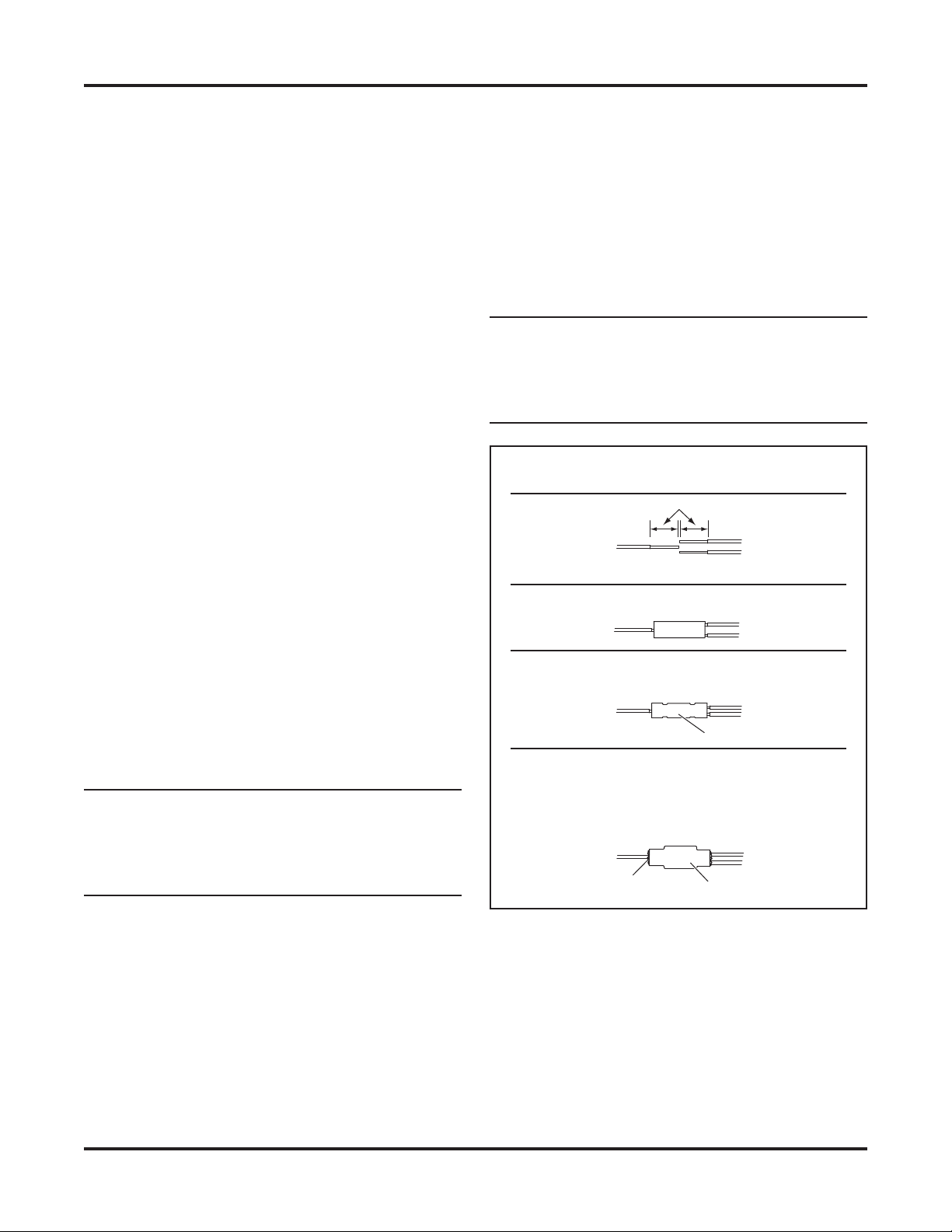
RECOMMENDED SPLICING
PROCEDURE
1. Locate the wire to be spliced into.
2. Cut the wire at least 1-1/2" from any other splice,
connector, or terminal. If wires are covered by
tubing or braid, remove enough of it to achieve the
minimum clearance required.
3. Strip away 5/16" of the insulation from the ends of
the wires to be spliced.
4. Slide two wires into one end of the supplied
parallel splice.
5. Place a piece of heatshrink tubing
(3/16" x 1-1/4" long) over the remaining wire to be
spliced. Cut tubing into 1-1/4" lengths if required.
6. Insert the wire into the open end of the splice and
crimp using an appropriate crimp tool. One or
two crimps may be necessary to ensure a good
connection. No wire strands should be visible
outside of the splice.
9. Check circuits for continuity.
10. Cover the splice with heatshrink tubing. The tubing
should extend beyond the splice on both sides.
11. Using a hot air source, starting in the center and
working to either side, apply heat until the tubing
recovers and glue can be seen around the edges.
Allow the tubing to cool before handling.
NOTE: The splices supplied will accommodate
18-gauge wires as shown. For larger-gauge wires,
cut the wire, strip the ends 3/8" to 1/2", and twist
together. Apply solder to the splice and cover with
heatshrink tubing.
Splicing Procedure
5/16"
From OEM
From park, turn,
or DRL lamp
Insert wires into splice.
vehicle harness
From plug-in
harness
7. Preheat a soldering tool for at least one minute to
help promote even solder fl ow.
8. Apply heat to the splice. Avoid heating too close to
the insulation. Apply solder to the wires, using just
enough solder to produce an even fl ow through
the splice. Use rosin core solder ONLY. Do not
use acid core solder.
NOTE: Avoid using an excessive amount of solder
as it can result in wicking. Wicking occurs when
solder travels up the wire core. This may cause
the wire to become stiff or brittle, which could
lead to a broken or open circuit.
Crimp and solder each splice.
Butt Splice
Cover the splice with heatshrink tubing.
Using a hot air source, apply heat until tubing
recovers and glue can be seen around the
edges. Allow tubing to cool before handling.
Glue
Heatshrink Tubing
Lit. No. 74033, Rev. 01 17 November 15, 2019

29049, 29051, 29053, 29400-7
Copyright © 2019 Douglas Dynamics, LLC. All rights reserved. This material may not be reproduced or copied, in whole or in part, in any
printed, mechanical, electronic, fi lm, or other distribution and storage media, without the written consent of the company. Authorization to
photocopy items for internal or personal use by the company's outlets or snowplow owner is granted.
The company reserves the right under its product improvement policy to change construction or design details and furnish equipment when
so altered without reference to illustrations or specifi cations used. This equipment manufacturer or the vehicle manufacturer may require or
recommend optional equipment for snow removal. Do not exceed vehicle ratings with a snowplow. The company off ers a limited warranty for
all snowplows and accessories. See separately printed page for this impor tant information. The following is an unregistered (™) trademark
of Douglas Dynamics, LLC: EdgeView™.
Printed in U.S.A.
Lit. No. 74033, Rev. 01 18 November 15, 2019
 Loading...