

Page 1
Page 1 of 5
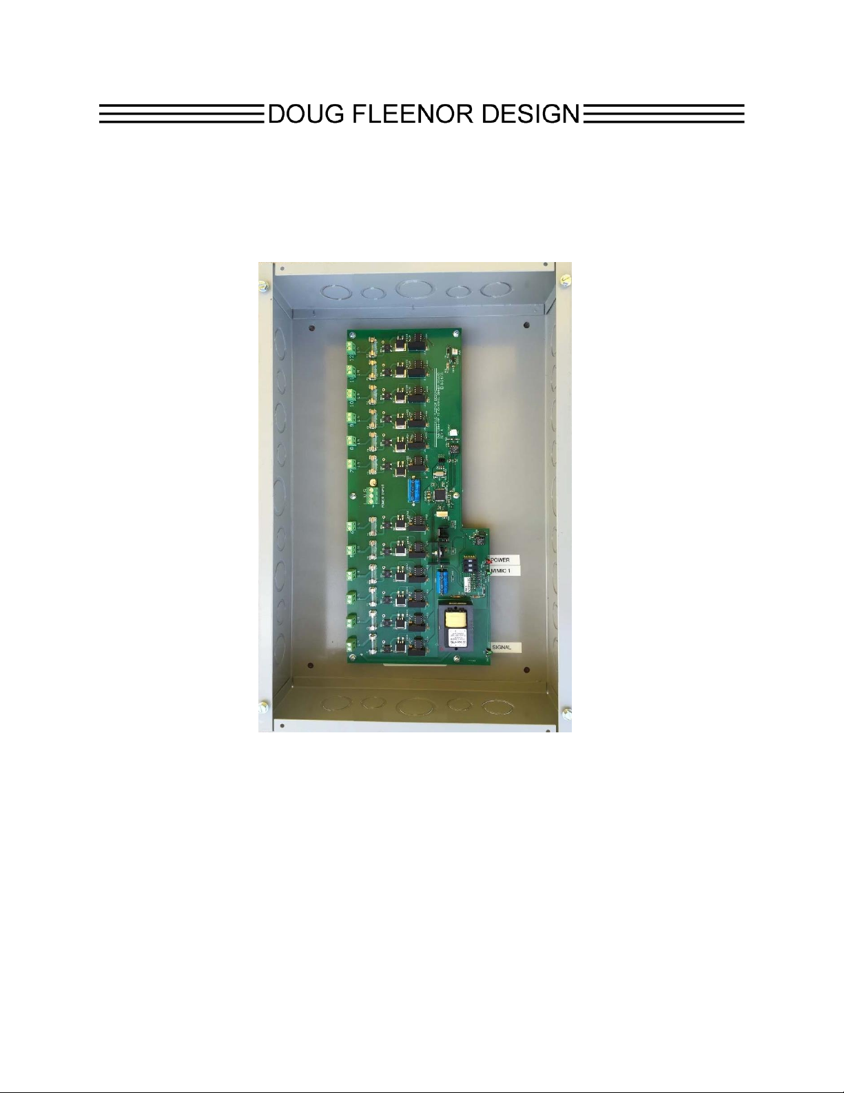
Model DMX12DIM ELV-JBOX
Installation and Operations Manual
Manual revision
May, 2018
Doug Fleenor Design, Inc.
396 Corbett Canyon Road
Arroyo Grande, CA 93420
(805) 481-9599 Voice and FAX
Page 2

Page 2 of 5
Product description
The DMX12DIM ELV-JBOX is a 12 channel, 100 Watt per channel dimmer. It is fed by a
single 120VAC 15A branch circuit. Each of the dimmers can be separately controlled using a
typical DMX512-based lighting controller. The dimmers use MOSFET power devices. The
dimmed outputs are Electronic Low Voltage (ELV) compatible using reverse phase (aka:
trailing edge) control techniques The DMX12DIM ELV-JBOX is housed in a standard NEMA1
electrical enclosure. Knockouts are provided for easy installation.
Safety warnings
The DMX12DIM ELV-JBOX should only be installed by qualified personnel in
accordance with local electrical codes.
There are no user serviceable parts in the DMX12DIM ELV-JBOX. Servicing should be
referred to qualified service personnel.
Do not operate the DMX12DIM ELV-JBOX without the cover installed.
Turn off all power to the DMX12DIM ELV-JBOX before installing. Do not attempt to wire
or install any part of the DMX12DIM ELV-JBOX with the power on.
Environmental
Operating temperature: 0-40º C
Operating humidity: 10-90% non-condensing
Indoor use only
Electrical ratings
Input: 120VAC, 60Hz, 15A
Output: 12 outputs, 120VAC, 100W each, 1,200W total maximum
Certification
The DMX12DIM ELV-JBOX is ETL Listed under safety Standard UL 508
Mounting
The DMX12DIM ELV-JBOX can be mounted on any stable surface in compliance with local
electrical codes. To mount the DMX12DIM ELV-JBOX:
Remove the cover by loosening the front panel screws
Select the desired mounting location
Locate the mounting holes using the DMX12DIM ELV-JBOX as a guide
Secure the DMX12DIM ELV-JBOX to the surface using appropriate fasteners
After all wiring is complete and switches have been configured (see below), install the
cover and secure it in place.
Page 3

Page 3 of 5
General installation notes
If enclosure knock-outs are used or if holes are punched in the enclosure for wire
entries, the holes must have appropriate bushings or conduit fittings installed to protect
the wires from cuts and abrasion.
Safety grounding must be maintained through this product. Metallic conduit may be
used for grounding if it is appropriately bonded to the enclosure.
Power input (line) wiring
Supply the DMX12DIM ELV-JBOX with a protected branch circuit of no more than 20A. The
power input terminals on the DMX12DIM ELV-JBOX are rated for #12AWG copper wire
(maximum). The torque rating for the terminals is 4.51 IN/LB.
Input power wiring must enter the enclosure and route directly to the input power
terminals without crossing over the circuit board or any control wiring.
Power output (load) wiring
Each output can supply a 100W (maximum) 120VAC load. The output terminals are rated for
#12AWG copper wire (maximum). The torque rating for the terminals is 3.5 IN/LB.
Load wiring must enter the enclosure and route directly to the input power terminals
without crossing over the circuit board or any control wiring.
Load terminals (1 and 2 of 12 shown)
Page 4

Page 4 of 5
Control cable wiring
Control cabling must enter the enclosure and route directly to the control input terminals. The
installer must secure low voltage control cabling such that it cannot come in contact with high
voltage line or load wiring.
The DMX512 control signal is connected to the DMX IN terminal block. A cable appropriate for
use with DMX512 must be used. Examples include Belden 9829, Belden 9729, or their equal
by other manufacturers.
The shield of the cable is connected to the DMX IN “C” terminal. The first twisted pair of wire
is to be connected to the DMX IN “ -“ and “+” terminals. If a second twisted pair is present in
the control cable, it should NOT be connected. The spare pair should either be trimmed back
or secured such that it cannot come in contact with any other parts of the DMX12DIM ELVJBOX.
Selecting dimmer modes of operation
All dimmers in the DMX12DIM ELV-JBOX are configured for reverse phase firing (ELV)
operation. Individual dimmers may be set for forward phase firing or non-dim operation.
Contact Doug Fleenor Design for guidance on how to change these configurations in the field.
Setting the address switches
The ADDRESS switches are used to select the DMX512 starting address for the
DMX12DIM ELV-JBOX.
The starting address can be set to any value from 1 to 512. The starting address represents
the address to be used for output 1 of the DMX12DIM ELV-JBOX. The second output will
respond to the next DMX512 slot, etc. Setting the address switches to 000 is the same as
setting to address 001.
Page 5

Page 5 of 5
Local control
Local control mode is used to turn on selected outputs without the use of a DMX512 signal
source. Setting the address switches to the range of 601-612 will turn on each output
individually. 601 will turn on output 1, 602 will turn on output 2, etc.
Setting the address switches to 699 will cause all outputs to go to full with no DMX512 signal
present.
Setting the address switches to 698 will cause all outputs to go to full if a valid DMX512 signal
is being received. All outputs will turn off while no DMX512 signal is present.
Setting the address switches to 697 will cause all outputs to go to full if any DMX512 level is
above 1%. All outputs will turn off while no DMX512 signal is present.
LED indicators
The LED indicators on the DMX12DIM ELV-JBOX have the following functions:
LED label Function
SIGNAL On when DMX is present, flashes when local control is active
MIMIC 1 Tracks the current level of dimmer 1 for troubleshooting purposes
PWR On when power is on
Warranty
Products manufactured by Doug Fleenor Design carry a five year parts and labor warranty
against manufacturing defects. It is the customer's responsibility to return the product to Doug
Fleenor Design (at the customer's expense). Doug Fleenor Design will repair the unit and
return it to the customer (at Doug Fleenor Design's expense). If a trip is necessary to the
customer's site to solve a problem, the expenses of the trip must be paid by the customer.
1. Note that this warranty is against Manufacturing Defects. It does not include damage due to
misuse or abuse. Most non-warranty repairs are made for a fixed $30.00 fee.
 Loading...