

Page 1
DOUG FLEENOR DESIGN
(805) 481-9599
Model: NODE4
802.3 Ethernet to DMX512 Gateway
OWNER'S MANUAL
Revision 2.0
January 2013
Software V1.3 and V1.4
Doug Fleenor Design
396 Corbett Canyon Road
Arroyo Grande, CA 93420
(805) 481-9599
Page 2

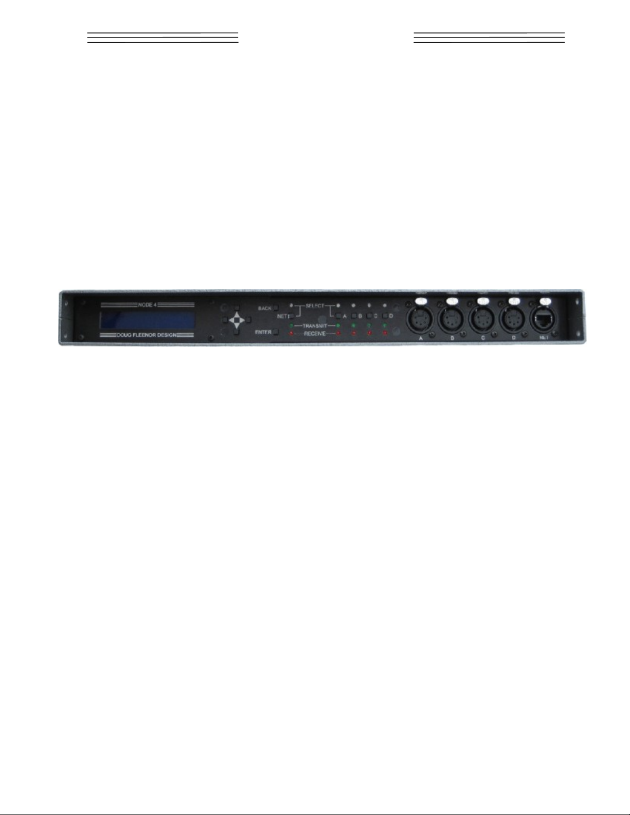
Overview
The NODE4 is an Ethernet to DMX bridging device. It accepts Artistic License's ArtNet
(version 3 or prior), PLASA’s Streaming ACN (ANSI E1.31), or Draft Streaming ACN
protocols. There are four fully isolated DMX512 ports. Each port can be configured as
either an input or as an output. Each of the connectors can be mounted on either the front
or rear panel. Their location can be changed in the field to accommodate fixed or touring
installations.
The factory default configuration covers most applications. An easy to use control panel
gives access to all network settings if a change is needed. The backlit 2 line by 20
character LCD and LED indicators give quick status feedback.
To configure the NODE4 ports, choose what you want to set up by pressing the port or
network adapter SELECT key. Use the arrow keys to find the option you want to change
and press ENTER. Use the arrows to change the value and press ENTER again to save.
You can use the BACK key at any time to disregard changes and return to the previous
menu.
The NODE4 features a universal input power supply and a rugged enclosure. An optional
rack mounting kit is available (model RK16-1). Holes are provided for truss mounting using
a C-clamp or half-coupler.
2 of 15
Page 3

DMX PORT SPECIFICATIONS
Port circuit: EIA-485 transceiver with 120 ohm termination between Data+ and Data-
NOTE: This product uses slew-rate-limited output drivers. Slew-rate-limited
drivers minimize EMI and reduce reflections.
Input signal: 0.2 Volts minimum, 12 Volts maximum
Output signal: 1.5 Volts (minimum) into 120 Ohm Termination
Connectors: Female Neutrik DL-series gold plated 5 pin XLR
(standard female connectors, male on request)
Port protection: +60V continuous, +15KV transient
Isolation: 600 Volts
ETHERNET SPECIFICATIONS
Ethernet circuit: 100BASE-TX Fast Ethernet, MDIX, and Auto Negotiation
Connector: Neutrik Ethercon
Isolation: 1500 Volts
MAIN SPECIFICATIONS
Power input: 6W, 100 to 240 VAC 50/60 Hz
Color: Front/Back: Black
Top/Bottom/Sides: Silver hammertone
Size and weight: 10.375" deep, 1.7" high, 16.5" wide 6 pounds
3 of 15
Page 4
Setup and Operation
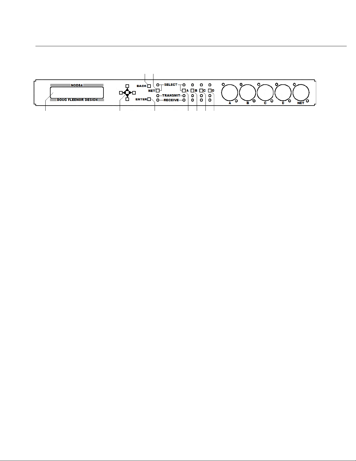
Front Panel User Interface
3 5
1 2 4 6 7 8 9
1) 20x2 Character LCD screen: Used to show data to the user based on the current
selection. After power up, the display shows the unit's current name and IP address.
2) Direction Pad: Consists of UP, DOWN, LEFT, and RIGHT keys. Use these keys to edit
configuration items and navigate the menu system.
3) BACK key: The BACK key is used to return to the HOME screen from one of the
information screens or to exit an editing screen without saving the changes.
4) ENTER key: Used to edit the item you are currently viewing. When editing of a
parameter is complete, press ENTER again to save the changes.
5) NET key: The NET key is used to enter the network settings menu. From there the
DHCP mode, IP address, Subnet Mask, and network protocols can be changed, The MAC
address can also be viewed.
6,7,8,9) Keys A, B, C, and D: These keys are used to select the corresponding DMX512
port. In each port's menu, the universe and the port's input/output status can be edited. In
addition, the levels of each DMX512 channel on the selected port can be viewed.
10) Front panel LEDs (not referenced on the diagram): The LEDs show the status of each
of the NODE4 ports. When a port’s SELECT button is pressed, the blue LED above that
button illuminates to indicate that it is selected for viewing or editing. The green NET
TRANSMIT LED flickers while the NODE4 is sending data out on the Ethernet port. The
red NET RECEIVE LED flickers while the NODE4 is receiving data from the Ethernet port.
Each of the DMX512 ports has a green TRANSMIT LED and a red RECEIVE LED. The
TRANSMIT LED flickers while DMX512 data is being sent from the associated DMX512
port (output mode). The RECEIVE LED flickers while DMX512 data is being received on
the associated port (input mode).
The rate at which each of the TRANSMIT and RECEIVE LEDs flickers provides additional
diagnostic information. Each LED will change its state (on or off) when a new packet of
data is transmitted or received. For example, if one of the DMX512 ports is configured as
an input, the flickering RECEIVE LED will show the relative update rate of the incoming
signal.
4 of 15
Page 5
The Menu System
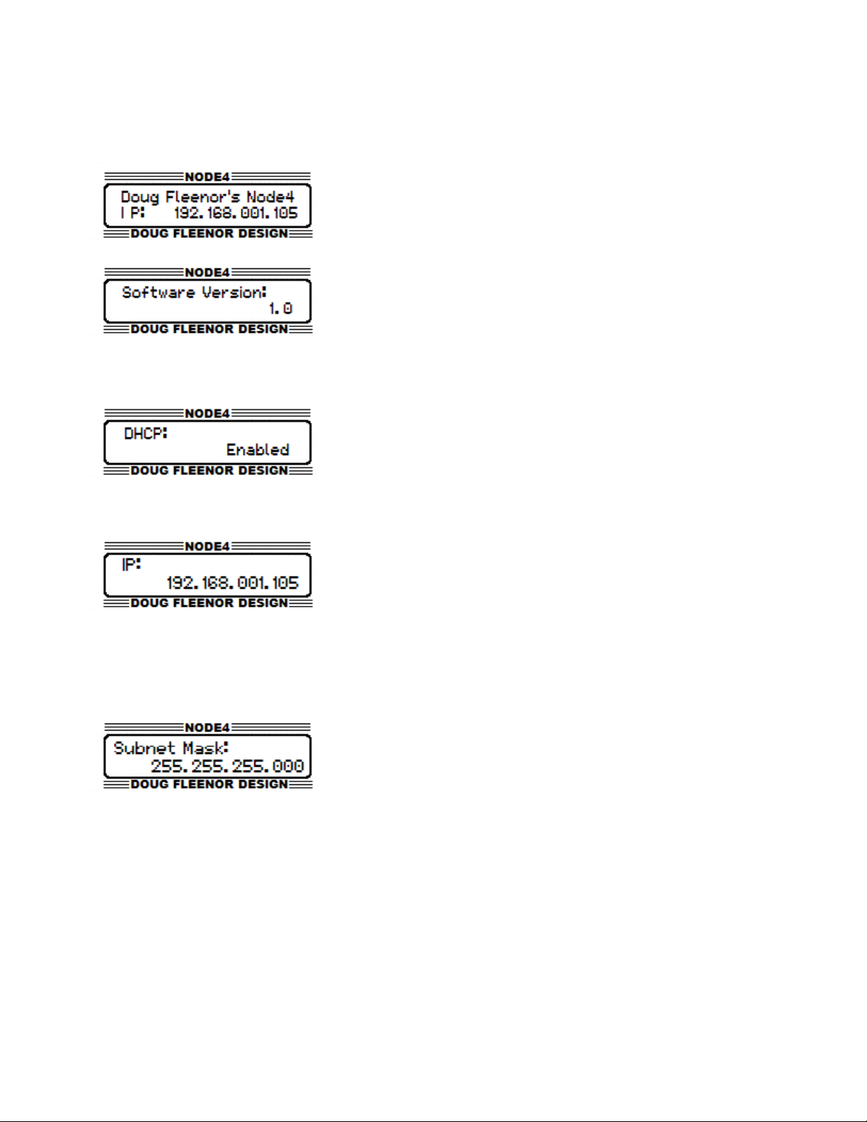
HOME Menu
The HOME page shows the unit's name and current IP
address. This is the default screen at startup, and you can
return to it at any time by pressing the BACK key until you
reach the HOME screen. Pressing the DOWN key from this
page will display the Software Version page.
The Software Version page shows the unit's current
software version. This page is located one page down from
the HOME page.
NET Select Menu
To Enable/Disable DHCP press the NET select key which
will take you to the network select menu. The first page
displayed is the DHCP Enable/Disable page. Press
ENTER to enable editing. Use the UP or DOWN keys to
select from Enable or Disable. When a final selection has
been made, press ENTER to save the changes. Press BACK to exit without saving.
To set the IP Address press the NET select key. This will
display the network select menu. Press DOWN once. The
e IP Address page will be displayed. Press ENTER to begin
editing the IP address. The IP address can not be edited if
DHCP is enabled. If DHCP is disabled, the LEFT and
RIGHT arrow keys can be used to select the digit to edit. Use the UP and DOWN arrow
keys to change the selected digit. After editing all digits, press ENTER to save changes.
Press BACK to exit without saving.
To set the Subnet Mask, press the NET select key. This
will display the network settings menu. Press the DOWN
arrow key twice to display the Subnet Mask page. Press
ENTER to edit the Subnet Mask. The Subnet Mask can
not be edited if DHCP is enabled. The UP and RIGHT
keys increase the number of ones in the Subnet Mask. The LEFT and DOWN keys
decrease the number of ones in the Subnet Mask. Configuring the Subnet Mask in this
fashion is consistent with the CIDR notation (More information can be found by searching
for CIDR online), and allows all valid Subnet Masks in the range from X.X.X.X/8 to X.X.X.X/
24 or 255.0.0.0 to 255.255.255.0.
5 of 15
Page 6

To view the Medium Access Control Address (MAC
Address), press the NET select key. This will display the
network settings menu. Press the DOWN arrow key three
times to display the MAC Address page. This value is not
configurable.
To set the Network Protocol, press the NET select key.
This will display the network settings menu. Press the
DOWN arrow key four times to display the Network
Protocol Page. Press ENTER to edit the mode. Use the
UP and DOWN arrow keys to cycle through the network
protocols supported by the NODE4. Press ENTER to select the desired protocol when it is
displayed. The NODE4 will save this setting and reboot. Press BACK to exit without
saving.
PORT Select Menu
To set the Universe for each DMX512 port, press the
corresponding port key (A, B, C, or D) for the port to be
configured. This displays the port settings menu. The first
page in the port setting menu is the universe page. The
current universe select for the selected port is displayed.
Press ENTER to edit the universe number. Use the LEFT
and RIGHT arrow keys to select the digit to edit. Use the
UP and DOWN arrow keys to change the value of the digit.
Press ENTER to save the value. Press BACK to exit
without saving. When the NODE4 is in Artnet mode, there
are two more pages below the Universe page to configure
the Artnet Subnet and Artnet Net. Use the same process to
access and configure these entries.
6 of 15
Page 7

To change the Direction of a port press the corresponding
port select key (A, B, C, or D) for the port to configured.
Press DOWN one time (or three times when in Artnet
Mode) to display the Port Direction page. Press ENTER to
edit the direction. Use the UP and DOWN arrow keys to
select between Input and Output modes. When the appropriate direction is displayed,
press ENTER to save the settings. Press BACK to exit without saving.
To view the DMX Levels of a port press the corresponding
select key for that port (A, B, C, or D). Press the DOWN
arrow key three times (or four times in Artnet mode) to
display the View Levels page. Press ENTER to view the
current levels on the port. The values are shown as 0 –
255 (0 to Full). Pressing the LEFT or RIGHT arrow keys
will scroll to view other channels. Pressing and holding the
LEFT or RIGHT arrow keys scrolls through channels at a
high rate. Press BACK to return to the View Channels
page.
Locking and Unlocking the front panel is accomplished
by navigating to the home (press BACK) screen and
holding the LEFT and RIGHT arrow keys for 2 seconds.
The NODE4 will display a locked message. Users may
navigate the menu system but, editing is disabled. To
unlock the unit, navigate back to the home screen (press BACK). Press and hold the
LEFT and RIGHT arrow keys for 2 seconds. The NODE4 will display an unlocked message
and users will be allowed to edit the configuration. Note that locking the front panel does
not disable web access.
7 of 15
Page 8

Using a web broswer to configure the NODE4
The NODE4 has a built-in web server that allows remote configuration of a unit across the
network. It allows for configuration of all aspects of the NODE4 including the front panel
name, unit description, network settings, and port options available for the current network
protocol.
To access the web server, the computer to be used must be physically connected to the
same network as the NODE4. It must be in the same Subnet, have the same Subnet
Mask, have a unique IP address, and have a web browser installed.
To start the web server, open a web browser (Internet Explorer, Mozilla Firefox, Google
Chrome, Safari, etc....).
In the address bar of the browser, type in the IP address of the NODE4. The IP address of
each NODE4 can be located on the HOME page of the device as shown in figure below. In
this example the IP address of this NODE4 is 192.168.1.105. After this address has
entered, press Enter on the computer keyboard. The Status Page from the NODE4 will be
displayed.
8 of 15
Page 9

On the Status Page the current status of the NODE4 can be seen. The uptime, number of
power cycles, software version, DHCP status, IP address, Subnet Mask, MAC Address,
DMX512 port Universe selections, and DMX512 port input/output status. A menu bar at
the top of the page has links to access the network settings and the DMX512 port settings.
In addition, there is a check box to identify the NODE4. While checked, the LCD backlight
on the currently selected NODE4 will blink.
9 of 15
Page 10

The Network Configuration page lets you set the Device Name, Description, IP Address,
Subnet Mask, DHCP settings, and Network Protocol. Be sure to click the Save Settings
button on the bottom right of the page before navigating away from this page. If another
page is selected before saving, all changes will be lost. If the IP, Subnet, or DHCP settings
have been changed, care must be taken to ensure it will still be possible to connect to the
NODE4 after saving the settings. The NODE4 may reboot after saving your new settings.
10 of 15
Page 11

The Port A, Port B, Port C, and Port D pages allow setting of the attributes of the
DMX512 ports. Be sure to click the Save Settings button before selecting another page.
11 of 15
Page 12

Operation of the NODE4
Upon Loss of DMX512 from the network, the NODE4 will continue to transmit its last
received DMX512 data for three seconds. It then stops transmitting DMX512 and disables
the the DMX512 line driver allowing moving lights and dimmers to reset or to let a Preset10
take control of the line.
Merging on the NODE4 is done automatically. Six network sources per port are allowed on
the NODE4. This means that a single port on the NODE4 set for universe one can
automatically merge six different sources which are generating universe one. In Streaming
ACN mode, priorities of the stream are also taken into account. For example, the NODE4
will automatically merge six sources with the same priority. If a new source with a higher
priority is received, the other sources will be rejected until the higher priority source has
timed out. If a port is set up to input DMX512 in Streaming ACN mode, that port will be
transmitted on the network with a priority of 100. This is the default priority for Streaming
ACN.
12 of 15
Page 13

Typical Layout
A typical network system will contain at least one console, one or more NODE4s, and an
Ethernet switch. In the system shown above, the console is connected by an Ethernet
cable to an Ethernet switch. An Ethernet cable is connected from the switch to each
NODE4. Category 5e or higher cabling is required for 100Mbs operation in an Ethernet
network.
Network Setup
There are a number of considerations when connecting and configuring a lighting control
network. The first option to consider is whether the system IP addresses will be
dynamically assigned by a DHCP server or if static assigned IP addresses will be used.
Doug Fleenor Design's NODE4 is capable of either DHCP or static IP addressing schemes.
Doug Fleenor Design recommends using static IP addresses in an entertainment lighting
control network. In a static IP environment, the user will manually set the IP address of
each unit in the network. Care must be taken to make sure that each NODE4 has the
same subnet mask and that each unit has a unique IP address in that subnet. The NODE4
comes from the factory with a static IP in the range of 10.X.X.X, which is based on its MAC
address. Note that when DHCP is enabled and no DHCP server is available (such as
when physically connected to the console), the NODE4 will use its currently programmed
static IP address. On loss of the Ethernet link (such as when the network cable is
unplugged from the unit), the NODE4 will revert back to its programmed static IP. In a
DHCP environment, IP address and Subnet Masks for the NODE4 are configured
automatically from the DHCP server. Most routers have a built-in DHCP server.
13 of 15
Page 14

The other major consideration is what network protocol to use. There are three network
protocols supported by the NODE4. They are ANSI E1.31(Streaming ACN), Draft
Streaming ACN, and Artistic License's Artnet Version 3 or prior. Doug Fleenor Design
highly recommends the use of ANSI E1.31 Streaming ACN in networks for its scalability
and higher performance characteristics. Streaming ACN has no restrictions on IP whereas
an Artnet IP must be in the range 2.X.X.X or 10.X.X.X with a subnet of 255.0.0.0.
Other things to consider when designing and configuring a network.
1) Try not to mix network protocols (Do not use Artnet and Streaming ACN in the same
network if it can be avoided.)
2) When selecting of an Ethernet switch, a managed switch must be used. Most Ethernet
switches now have broadcast storm control which must be disabled to allow entertainment
lighting protocols to pass through.
3) Use the same subnet mask on all network devices, but be sure it is big enough to fit the
number of devices on the network.
4) Doug Fleenor Design strongly recommends that lighting control networks should not be
connected to the Internet. It is recommend that the lighting network is a completely
separate network with no Internet access.
5) Be aware of the rules for Artnet IP addresses. Artnet requires the IP to be in the range
of either 2.X.X.X or 10.X.X.X and the subnet must be 255.0.0.0. These must be followed
for the NODE4 to inter-operate completely with other Artnet Gear.
6) If there will be more than 100 network universes in a connected network, a managed
Layer 3 network should be considered.
14 of 15
Page 15

Warranty
Products manufactured by Doug Fleenor Design carry a five year parts and labor warranty
against manufacturing defects. It is the customer's responsibility to return the product to
Doug Fleenor Design (at the customer's expense). If covered by warranty, Doug Fleenor
Design will repair the unit and return it to the customer (at Doug Fleenor Design's
expense). If a trip is necessary to the customer's site to solve a problem, the expenses of
the trip must be paid by the customer.
Note that this warranty is against Manufacturing Defects. It does not include damage due to
misuse, abuse, or "acts of God". Most non-warranty repairs are made for a fixed $30.00
fee, plus shipping.
15 of 15
 Loading...