

Page 1
For the latest updates and more information, visit our website at
www.doublesight.com
Pa rt No . 90- X- DS 263 N- EUE X0 3
Ma de i n K or ea
DoubleSight DS-263N
LCD MONITOR
USER'S MANUAL
Page 2

Contents
Contents
Contents.............................................................................................................. 1
Preface................................................................................................................ 2
Installation........................................................................................................... 4
Unpacking...................................................................................................................... ........................4
Adjust angle of Tilt stand ................................................................................................................. .5
Connecting the Display......................................................................................................... ............5
Connecting the AC Power................................................................................................................ 5
Setting Up the LCD Monitor ............................................................................................................5
Power Management System ........................................................................................................ ...5
Display Controls.................................................................................................. 6
User Controls ........................................................................................................................................6
Adjusting the Monitor's Display................................................................................................ .....7
Function Description .........................................................................................................................8
OSD Lock Out Function.................................................................................................................. 13
Technical Information ....................................................................................... 14
Specications................................................................................................................. ....................14
Troubleshooting ................................................................................................ 18
Page 3
Preface Important Safety Instructions
Important Safety Instructions
Preface
FCC Statement Warning
• Reposition or relocate the receiving antenna.
• Increase the separation between the equipment and the receiver.
• Connect the equipment into an outlet on a circuit dierent from that to which the receiver is connected.
• Consult the dealer or an experienced monitor technician for help.
Warning
This manual is designed to assist users in setting up and using the LCD Monitor. Information in this document has been carefully
checked for accuracy; however, no guarantee is given to the correctness of the contents. The information in this document is
subject to change without notice. This document contains proprietary information protected by copyright. All rights are reserved.
No part of this manual may be reproduced by any mechanical, electronic or other means, in any form, without prior written
permission of the manufacturer. Windows is a registered trademark of Microsoft Inc. Other brand or product names are
trademarks of their respective holders.
This equipment has been tested and found to comply with the limits for a Class B digital device, pursuant to Part 15 of the FCC
Rules. These limits are designed to provide reasonable protection against harmful interference in a residential installation.
This equipment generates, uses, and can radiate radio frequency energy, and if not installed and used in accordance with the
instruction, may cause harmful interference to radio communications. However, there is no guarantee that interference will
not occur in a particular installation. If this equipment does cause harmful interference to radio or television reception, which
can be determined by turning the equipment o and on, the user is encouraged to try to correct the interference by one or
more of the following measures:
Use only shielded signal cables to connect I/O devices to this equipment. You are cautioned that changes or modications not
expressly approved by the party responsible for compliance could void your authority to operate the equipment.
This device complies with part 15FCC Rules. Operation is subject to the following two conditions(1) This device may not cause
harmful interference. (2) This device must accept any interference received, including interference that may cause undesired
operation.
Please read the following instructions carefully. This manual should be retained for future use.
1. To clean the LCD Monitor screen:
-- Power o the LCD Monitor and unplug the AC Cord.
-- Spray a non-solvent cleaning solution onto a rag.
-- Gently clean the screen with dampened rag.
2. Do not place the LCD Monitor near a window. Exposing the monitor to rain water, moisture or sunlight can
severely damage it.
3. Do not apply pressure to the LCD screen. Excess pressure may cause permanent damage to the display.
4. Do not remove the cover or attempt to service this unit by yourself. Servicing of any nature should be performed
by an authorized technician.
5. Store the LCD Monitor in a room with a room temperature of -20° ~ 60°C (or -4° ~ 140°F). Storing the LCD Monitor
outside this range could result in permanent damage.
6. If any of the following occurs, immediately unplug your monitor and call an authorized technician.
* Monitor to PC signal cable is frayed or damaged.
* Liquid spilled into LCD Monitor or the monitor has been exposed to rain.
* LCD Monitor or the case is damaged.
7. Only use the supplied main lead to connect the monitor. For a nominal current up to 6A and a device weight
above 3 kg, a line not lighter than H05VV-F, 3G, 0.75 mm
2
must be used.
Important Recycle Instruction:
Contains Mercury, Dispose of Properly.
Lamp(s) inside this product contain mercury. This product may contain other electronic waste that
can be hazardous if not disposed of properly. Recycle or dispose in accordance with local, state, or
federal Laws. For more information, contact the Electronic Industries Alliance at WWW.EIAE.ORG.
For lamp specic disposal information check WWW.LAMPRECYCLE.ORG.
Page 4
Installation Installation
Adjust angle of Tilt stand
esaB * ediuG s'resU * rotinoM DCL *
* Monitor-to-PC VGA Cable * Monitor-to-PC DVI-D Cable (optional by model type)
droC rewoP *
* Monitor-to-PC "Up to Down" USB cable(optional by model type)
Before unpacking the LCD Monitor, prepare a suitable workspace for your Monitor and computer. You need a
stable and clean surface near a wall power outlet. Make sure that LCD Monitor has enough space around it for
sucient airow. Though the LCD Monitor uses very little power, some ventilation is needed to ensure that the
Monitor does not become too hot.
After you unpack the LCD Monitor, make sure that the following items were included in the box:
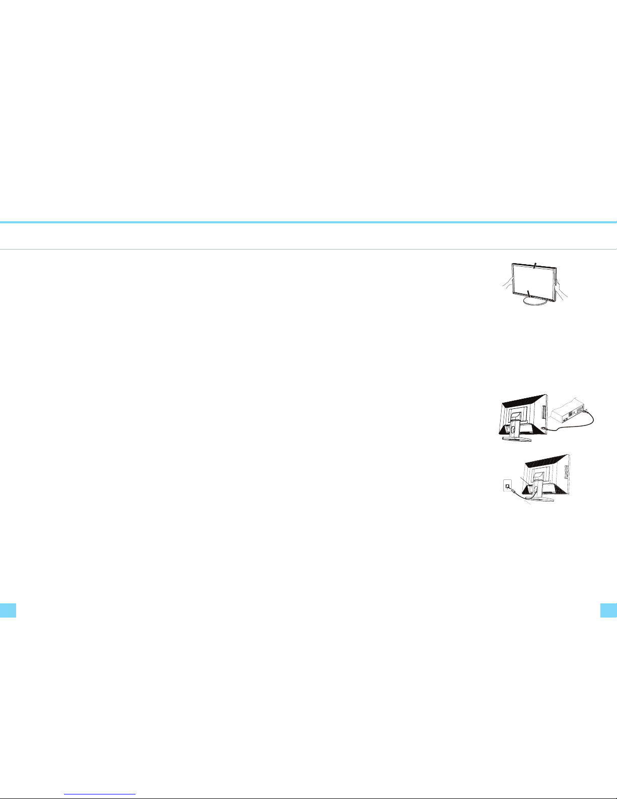
The monitor screen may be tilted (-5 to 40 degree).The place hands on each
side of the monitor screen and lift or lower to the desired height as
shown in the right gure.
20
o
5
o
Figure 1-1
CAUTION:
* To lower the monitor screen place hands on each side of the monitor
screen to avoid catching your hand and ngers between the monitor
screen and the tilt stand base.
*Do not push surface of the monitor screen strongly and not scratch it
with your nails when you adjust the position of the monitor screen.
Otherwise you might be injured or the display could be damaged.
Note:
When you tilt the monitor pass 40 degrees, you will hear clicking noise. Tilting pass 40 degrees becomes harder than
tilting within 40 degrees.
.
Connecting the Display
1. Power o your computer.
2. Connect one end of the signal cable to the LCD Monitor’s VGA
port or DVI-I or DVI-D port. (See Fig 1-2)
3. Connect the other end of the signal cable to the VGA port or
DVI-I or DVI-D port on your PC.
4. Make sure connections are secure.
Figure 1-2
Connecting the AC Power
1. Connect the power cord to the LCD Monitor.(See Fig. 1-3)
2. Connect the power cord to an AC power source.
AC Power Jack
Power Cord
Figure 1-3
Setting Up the LCD Monitor
1. Make sure the AC power cord is connected to the LCD Monitor.
2. Press the power button located on the bezel of the monitor.
3. Once a signal is received, the monitor should automatically adjust. If not, push the “AUTO” button located
on the bezel of the monitor.
Power Management System
This LCD Monitor complies with the VESA DPM Power Management guidelines. If you have VESA's DPM™
compliance display card or software installed in your PC, the monitor can automatically reduce its power
consumption when not in use. If input from keyboard, mouse or other input devices is detected by the
computer, the monitor will automatically "wake up". When the LCD Monitor is in power saving mode, the
monitor screen will be blank and the power LED indicator will light yellow.
Page 5
Display Controls Display Controls
Adjusting the Monitor's Display
User Controls
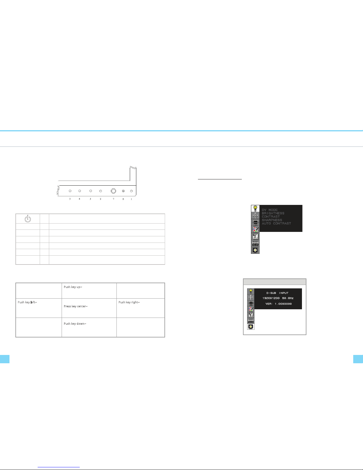
A brief description and the location of all LCD Monitor functions controls and indicators
Figure 2-1
1
Push to turn ON or turn O.
MENU 2
Activates OSD main menu.
EXIT 3
Exit OSD display / DV mode hot key.
SOURCE 4
Select DVI-D / DVI-I (digital) / DVI-I (analog) / D-SUB signal source. (Toggle Switch)
AUTO 5
Hot key for manually auto adjusting the display.
LED 6
Green when the monitor is on, Amber when in power saving mode, and Dark when o.
4D+1 7
A four direction key plus enter/exit button. Allows you to move up, down, left, right or
pressed. See function chart below.
4D+1 Key Function Denition
Push key up~
Hot Key: Contrast +
Menu : Cursor Up
Push key left ~
Hot Key: Brightness Menu: Cursor Left
/ Volume -
Press key cen ter~
Item Enter / Exit
Push key righ t~
Hot Key: Brightness +
Menu: Cursor right
/ Volume +
Push key down ~
Hot Key: Contrast -
Menu: Cursor Down
The monitor has four function control buttons to select among functions shown on OSD menu, designed for
easy user-viewing environments.
OSD Function Menu
To activate the OSD Main menu, simply press ”Menu” button , the menu diagram will pop up on the screen as
shown on Fig. 2-2
Use the 4D+1 key to navigate through the function you want to adjust. Push the 4D+1 key to enter a sub-menu
and adjust the value. Push the 4D+1 key again to exit the sub-menu. Pressing the "Exit" buttons allows you to
exit the OSD menu at any time. Pressing the "Menu" key gets you back to the main menu.
Figure 2-2
Menu under input
Attention
Firmware revision may have been updated into a latest version while the version number shown on informati
on item in OSD menu will stay as Ver 1
Information OSD
Figure 2-3
Page 6
Display Controls Display Controls
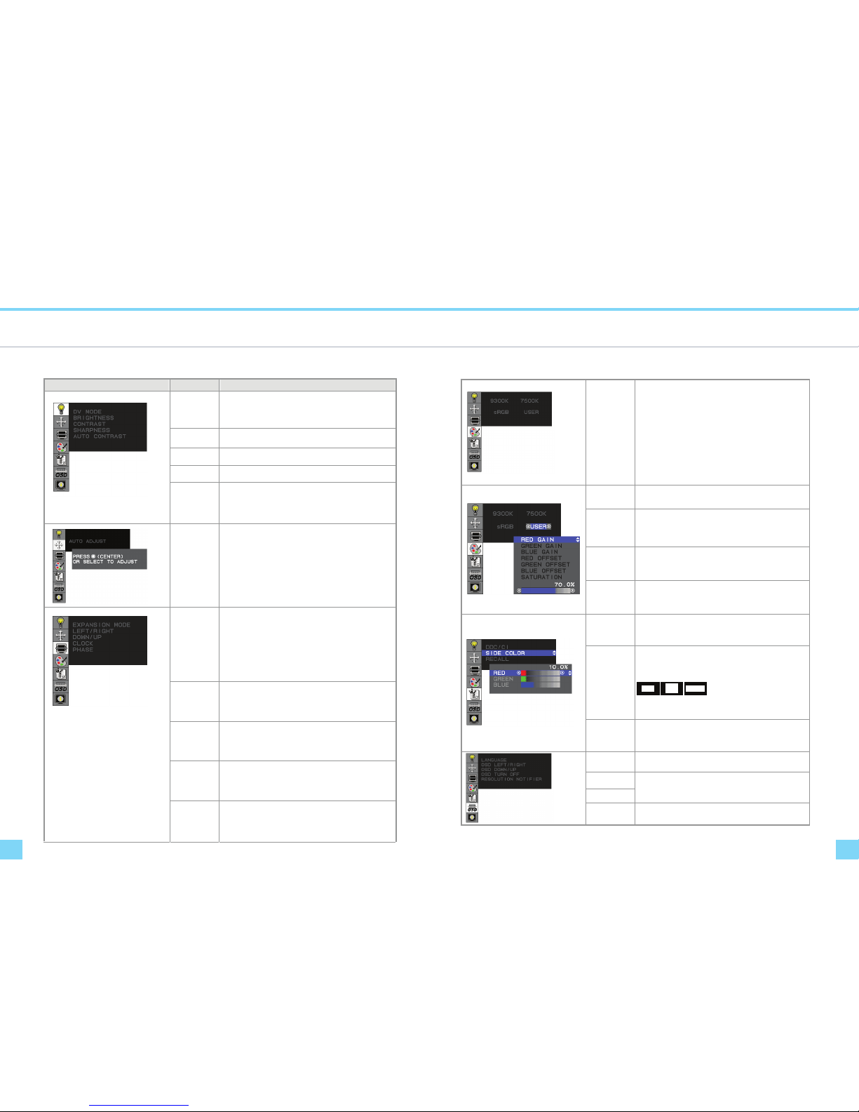
Function Description
Function Description
Figure Function Function Description
DV MODE
The following DV mode display setting can be selected by
OSD (STANDARD/TEXT/sRGB/MOVIE/GAMING/PHOTO)
Default setting: TEXT
BRIGHTNESS
Adjust the brightness.
Factory setting: 100.0%
CONTRAST
Adjust the image contrast.
Factory setting:50.0%
SHARPNESS
Adjust the sharpness.
Factory setting: 50%
AUTO
CONTRAST
(D-SUB or DVI-I
Analog signal
Only)
Adjust the CONTRAST to the optimal value for the
video-input level automatically.
AUTO ADJUST
(D-SUB or DVI-I
Analog Input
Only)
Adjust the H.POSITION, V.POSITION, H-SIZE and FINE to
the optimal value automatically.
EXPANSION
MODE
This function allows you to choose from dierent display
modes:
Full: expands all resolution to full screen.
Aspect: enlarges native resolution to either horizontal or
vertical limit.
Real: displays native resolution.
Default setting: FULL
LEFT/RIGHT
(D-SUB or DVI-I
Analog Input
Only)
Adjust the horizontal image position.
DOWN/UP
(D-SUB or DVI-I
Analog Input
Only)
Adjust the vertical image position.
CLOCK
(D-SUB or DVI-I
Analog Input
Only)
Adjust the sync frequency of internal pixel clock.
PHASE
(D-SUB or DVI-I
Analog Input
Only)
Adjust the value for improve display focus.
Color
Temperature
Choose dierent color temperature
(9300K, 7500K, sRGB, USER).
Default is USER.
USER mode adjustable.
Adjust the contrast and brightness of each color of the
white balance.
RED
GREEN
BLUE
GAIN
Allows you to adjust the Red/Green/Blue color gain.
RED
GREEN
BLUE
OFFSET
Allows you to adjust the Red/Green/Blue color oset.
SATURATION
Adjust color depth, increasing this value makes pictures
more colorful, decreasing makes pictures less colorful.
Adjustable value from -100 to 100.
Factory setting: 0
DDC/CI
DDC/CI allows you to control certain settings of the
monitor via computer.
Default is ON.
SIDE COLOR
When "Full" is not selected in the "Expansion Mode" and
the resolution is under the LCD panel's native resolution,
the picture does not display at full screen. The
borders/sides around the picture can be customized.
Adjust "Side Color" to customize the color of the
border/sides around the picture.
RECALL
Reset all user settings to factory preset value except
language selection.
LANGUAGE Select a language for OSD menu.
OSD
LEFT/RIGHT
OSD UP/DOWN
Control the location of the OSD menu on the screen.
Factory setting: Center of the screen.
OSD TURN OFF
Select OSD Menu turn o time.
Factory setting: 45 seconds.
Page 7
Display Controls Display Controls
Function Description
Function Description
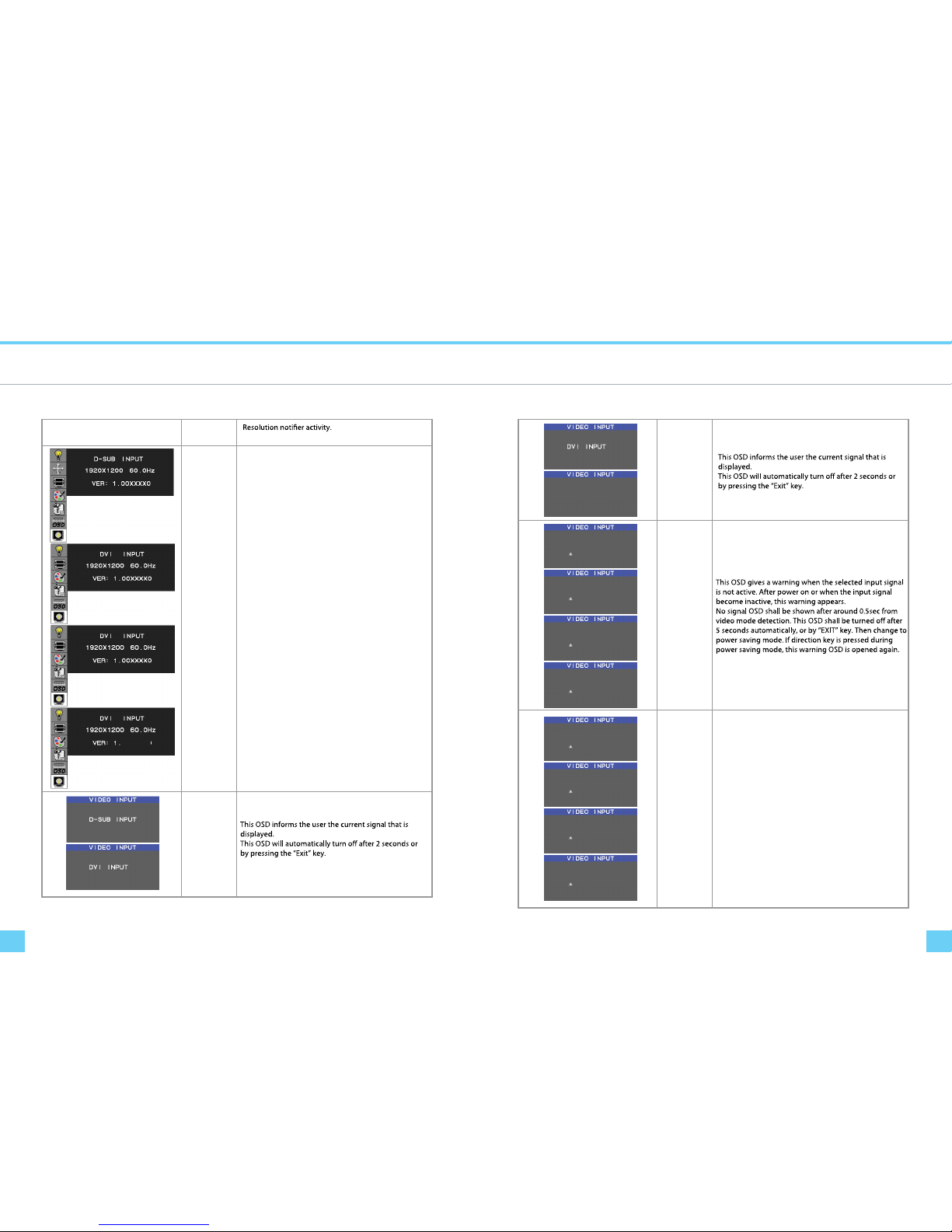
Information
Input Select
OSD Warnings
NO SIGNAL
OSD Warnings
OUT OF RANGE
Provide information about resolution, H/V frequencies,
and polarity of the input signal.
This function gives warning about input resolution or
refresh rate that the monitor cannot display.
If video signal is not at the proper timing when the
monitor powers on or input signal is changed, this
message opens and it disappears after 45 seconds,
or by "EXIT" key.
-D
ANALOG INPU
T
-D
Input Select
DVI ANALOG
D-SUB INPUT
NO SIGNAL
DVI-D
NO SIGNAL
DVI INPUT
NO SIGNAL
DVI ANALOG
NO SIGNAL
D-SUB INPUT
OUT OF RANGE
DVI-D
OUT OF RANGE
DVI INPUT
OUT OF RANGE
DVI ANALOG
OUT OF RANGE
RESOLUTION
NOTIFIER Factory setting: OFF
Page 8
Display Controls Display Controls
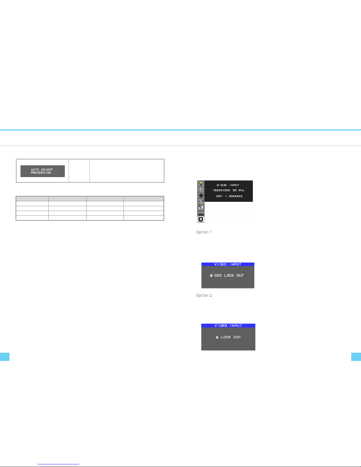
OSD Lock Out Function
Function Description
Auto Adjust
(Analog Input
Only)
When the monitor is displayed for the rst time and the
resolution is 800x600 and above, the monitor will auto
adjust itself.
To manually execute the Auto Adjust function, press the
Auto button.
Target color coordinates
Color Temp. 9300K 7500K sRGB
u’ 0.189 0.194 0.198
v’ 0.446 0.459 0.468
x 0.283 0.299 0.313
y 0.297 0.315 0.329
OSD Lock Function allows you to lock out the OSD menu and the button keys.
To activates the OSD lock function, the monitor must be in a normal display mode and the information menu as
shown in g-2-4 must be activated. Then follow the instructions below.
g-2-4
Option 1: OSD lock – all buttons be locked except the “POWER” button.
Press “Exit Key + Menu Key + Soft power key” at same time
The monitor will show a n “OSD Lock Out” message, sho wing time as “OSD TURN OFF ” setting, and the message be
show again by any button, also any button exit this message, but “Power” button be turn o / on monitor.
Only repeat this step to unlock.
Option 2: OSD & Power button lock – all buttons including “POWER” button be locked.
Press “Exit Key + Menu Key + Up key” at same time
The monitor will show a n “OSD Lock Out” message, sho wing time as “OSD TURN OFF ” setting, and the message be
show again by any button, also any button exit this message, but “Power” button no action.
Only repeat this step to unlock.
Page 9
Technical Information Technical Information
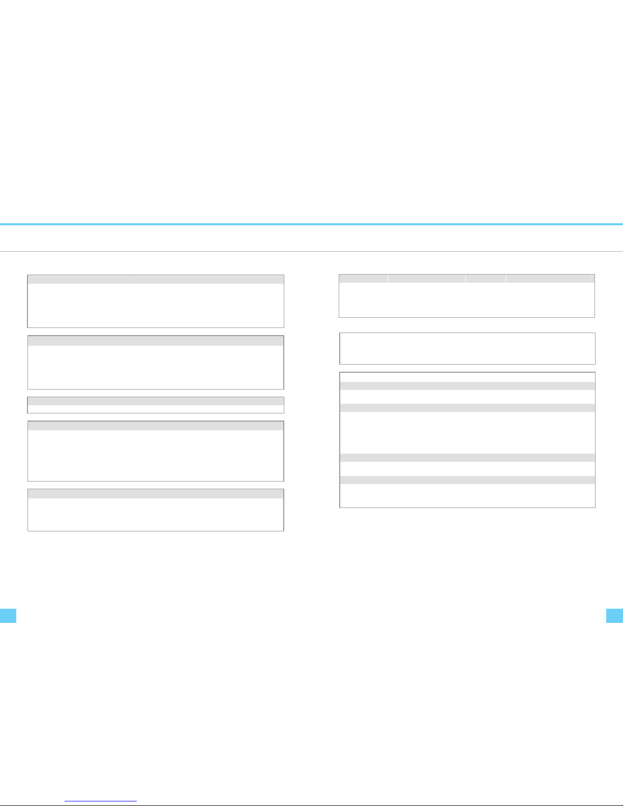
Power Management
Specications
LCD Panel
"62 eziS
DCL TFT roloc xirtam evitcA epyT yalpsiD
0021 x 0291 noituloseR
0021 x )BGR( x 0291 toD yalpsiD
)V x H( 8.343 x 80.055 )mm( aerA yalpsiD
)tib 8 BGR( M7.61 roloC yalpsiD
Video
Input Signal
Input Impedance
Polarity
Amplitude
Multi-mode Supported
Analogue RGB ; Digital TMDS
75 Ohm ± 2% (VGA)
Positive, Negative (VGA)
0 - 0.7 ± 0.05 Vp (VGA)
Horizontal Frequency: 31 ~ 93.75kHz
Vertical Frequency: 50 ~ 76 Hz
Control
rotacidni DEL htiw hctiws ffO/nO hctiws rewoP
OSD
Brightness
Contrast
Horizontal Position
Vertical Position
Phase
Clock
Display Mode Setup
Digital
Digital
Digital
Digital
Digital
Digital
Use EEPROM to save settings in memory
Others
USB Hub ( optional )
Upstream
Downstream
USB 2.0 Self Powered
1 ( Link to PC )
4 ( Link to Device)
Mode Power Consumption* AC Input LED Color
DPM ON 135W maximum 240 VAC Green
DPM OFF 2W maximum 240 VAC Amber
DC switch o 1W maximum 240 VAC Dark
Disconnected 2W maximum 240 VAC Dark
Meeting VESA DPM requirements measured from AC Input end of AC power cord.
eugolanA tupnI cnyS
bitapmoc LTT etarapeS langiS le horizontal and vertical
synchronization
evitagen dna evitisoP ytiraloP
Plug & Play
Supports VESA DDC2B functions
External Connection
Power Input (AC input) AC socket
rotcennoc bus-D nip-51 elbaC oediV
Environment
Operating Condition:
Storage Condition:
Temperature
Relative
Humidity
Temperature
Relative
Humidity
5°C to 40°C/41°F to 104°F
20% to 80%
-20°C to 60° C/-4°F to140° F
5% to 85%
Power Supply (AC Input)
zH 06 / 05 ,CAV042 ~ 001 ,esahp elgniS egatloV tupnI
mumixam A 5.1 tnerruC tupnI
Size and Weight
mm )D( 562 x )H( 9.754 x )W( 495 snoisnemiD
Net Weight
10.4 ± 0.3 kg
Gross Weight
13.1± 0.3 kg
Page 10
Technical Information Technical Information
Standard Timing Table
Standard Timing Table
TIMING NAME
FH (KHz)
FV (Hz)
SYNC
POLARITY
TOTAL
(DOT / LINE)
ACTIVE
(DOT / LINE)
SYNC
WIDTH
(DOT / LINE)
FRONT
PORCH
(DOT / LINE)
BACK
PORCH
(DOT / LINE)
PIXEL
FOREQ.(MHz)
640x350 31.469 + 800 640 96 16 48
VGA-350 70.087 – 449 350 2 37 60
25.175
640x400 31.469 – 800 640 96 16 48
VGA-GRAPH 70.087 + 449 400 2 12 35
25.175
640x480 31.469 – 800 640 96 16 48
VGA-480 59.94 – 525 480 2 10 33
25.175
640x480 35 – 864 640 64 64 96
APPLE MAC-480 66.67 – 525 480 3 3 39
30.24
640x480 37.861 – 832 640 40 16 120
VESA-480-72Hz 72.809 – 520 480 3 1 20
31.5
640x480 37.5 – 840 640 64 16 120
VESA-480-75Hz 75 – 500 480 3 1 16
31.5
720x350 31.47 + 900 720 108 18 54
70Hz 70.087 – 449 400 2 37 60
28.322
720x400 31.469 – 900 720 108 18 54
VGA-400-TEXT 70.087 + 449 400 2 12 35
28.322
832x624 49.725 – 1152 832 64 32 224
APPLE MAC-800 74.55 – 667 624 3 1 39
57.2832
800x600 35.156 + 1024 800 72 24 128
SVGA 56.25 + 625 600 2 1 22
36
800x600 37.879 + 1056 800 128 40 88
VESA-600-60Hz 60.317 + 628 600 4 1 23
40
800x600 48.077 + 1040 800 120 56 64
VESA-600-72Hz 72.188 + 666 600 6 37 23
50
800x600 46.875 + 1056 800 80 16 160
VESA-600-75Hz 75 + 625 600 3 1 21
49.5
848x480 31.02 + 1088 848 64 32 152
VESA 60 + 517 480 3 1 27
56.25
1024x768 48.363 – 1344 1024 136 24 160
XGA 60.004 – 806 768 6 3 29
65
1024x768 53.964 + 1328 1024 176 16 112
COMPAQ-XGA 66.132 + 816 768 4 8 36
71.664
1024x768 56.476 – 1328 1024 136 24 144
VESA-768-70Hz 70.069 – 806 768 6 3 29
75
1024x768 60.023 + 1312 1024 96 16 176
VESA-768-75Hz 75.029 + 800 768 3 1 28
78.75
1024x768 60.24 – 1328 1024 96 32 176
APPLE MAC-768 75.02 – 803 768 3 3 29
80
1152x864 54.054 + 1480 1152 96 40 192
(60Hz) 59.27 + 912 864 3 13 32
80
1152x864 63.851 + 1480 1152 96 32 200
(70Hz) 70.012 + 912 864 3 1 44
94.499
1152x864 67.5 + 1600 1152 128 64 256
(75Hz) 75 + 900 864 2 2 32
108
1152x870 68.68 – 1456 1152 128 32 144 100
If the selected timing is NOT included in table below, this LCD monitor will use the most suitable available timing.
(75Hz) 75.06 – 915 870 3 3 39
1280x720 44.772 – 1664 1280 128 64 192
(60Hz) 59.855 + 748 720 5 3 20
74.5
1280x960 60 + 1800 1280 112 96 312
(60Hz) 60 + 1000 960 3 1 36
108
1280x960 70 + 1800 1280 112 96 312
(70Hz) 70 + 1000 960 3 1 36
126
1280x960 75 + 1800 1280 112 96 312
(75Hz) 75 + 1000 960 3 1 36
135
1280x1024 64 + 1688 1280 112 48 248
VESA-1024-60Hz 60 + 1066 1024 3 1 38
108
1280x1024 80 + 1688 1280 144 16 248
VESA-1024-75Hz 75 + 1066 1024 3 1 38
135
1360x768 75 + 1792 1360 112 64 256
60Hz 75 + 795 768 6 3 18
85.5
1440x900 55.469 + 1600 1440 32 48 80
Red. BLKing 60Hz 59.901 – 926 900 6 3 17
88.75
1440x900 55.935 – 1904 1440 152 80 232
60Hz 59.887 + 934 900 6 3 25
106.5
1440x900 70.635 – 1936 1440 152 96 248
75Hz 74.984 + 942 900 6 3 33
136.75
1680x1050 64.674 + 1840 1680 32 48 80
Red. BLKing 60Hz 59.883 – 1080 1050 6 3 21
119
1680x1050 65.29 – 2240 1680 176 104 280
60Hz 59.954 + 1089 1050 6 3 30
146.25
1680x1050 82.306 – 2272 1680 176 120 296
75Hz 74.892 + 1099 1050 6 3 40
187
1600x1200 75 + 2160 1600 192 64 304
VESA-1200-60Hz 60 + 1250 1200 3 1 46
162
1600x1200 87.5 + 2160 1600 192 64 304
VESA-1200-70Hz 70 + 1250 1200 3 1 46
189
1600x1200 93.75 + 2160 1600 192 64 304
VESA-1200-75Hz 75 + 1250 1200 3 1 46
202.5
1920x1200 74.038 + 2080 1920 32 48 80
Red. BLKing 60Hz 59.95 – 1235 1200 6 3 26
154
1920x1200 74.566 – 2592 1920 200 136 336
60Hz 59.885 + 1245 1200 6 3 36
193.25
*** DVI signal can not support 1680X1050@75, 1600X1200@70, 1600X1200@75, 1920X1200@60 non reduce mode
Note: Mode 640x350, 640x400 and 720x400 will be locate on middle in the position and cannot be expanded to full
screen on vertical direction.
Page 11
Troubleshooting MEMO
Troubleshooting
PROBLEM Picture is unclear and unstable
PROBLEM There is no picture on LCD Monitor
PROBLEM There is no picture on LCD Monitor
This LCD Monitor has pre-adjusted using factory standard VGA timings. Due to the output timing dierences
among various VGA cards in the market, users may initially experience an unstable or unclear display whenever
a new display mode or new VGA card is selected.
Attention
This LCD Monitor Supports Multiple VGA Modes.
Refer to the Standard Timing Table for a listing of modes supported by this LCD Monitor.
The picture is unclear and unstable, please perform the following steps:
1. Enter PC to “Shut Down Windows” status while you’re in MS-Windows environment.
2. Check the screen to see if there’s any black vertical stripes appear. If there are, take advantage of the “Clock”
function in OSD menu and adjust (by increment or decrement numbers) until those bars disappear.
3. Move to “Phase” function in OSD menu again and adjust the monitor screen to its most clear display.
4. Click “No” on “Shut Down Windows” and back to the normal PC operating environment.
If there’s no picture on the LCD Monitor, please perform the following steps:
1. Make sure the power indicator on the LCD Monitor is ON, all connections are secured, and the system is
running on the correct timing. Refer to Chapter 3 for information on timing.
2. Turn o the LCD Monitor and then turn it back on again. If there is still no picture, press the Adjustment
Control button several times.
3. If step 2 doesn’t work, connect your PC system to another external CRT. If your PC system Functions properly
with a CRT Monitor but it does not function with the LCD Monitor, the output timing of the VGA card may be
out of the LCD’s synchronous range. Please change to an alternative mode listed in the Standard Timing
Table or replace the VGA card, and then repeat steps 1 and 2.
If you have chosen an output timing that is outside of the LCD Monitor’s synchronous range (Horizontal:
31 ~ 93.75 kHz and Vertical: 50 ~ 76 Hz), the OSD will display a “Out of Range” message. Choose a mode that is
supported by your LCD Monitor.
Also, if the signal cable is not connected to LCD monitor at all or properly, the monitor screen will display a
message “No Input Signal”.
 Loading...