

Page 1
PRODUCT USER MANUAL
INSTALLATION GUIDE
D2 COOLDOME™ ENCLOSURE
Product Models: D2-CD-12V D2-CD-24V
Page 2

Table of Contents
Limited Warranty Info ..………………………………………………………………………………………………………………………………………………………………………………... 0
Product Installation Precautions, Warnings, and Installation Guidelines ......................................................................................................... 1
Electrical Conduit Guidelines .......................................................................................................................................................................... 2
Vent Plugs Installation Guide ......................................................................................................................................................................... 3
Cable Management…………………………………………………………………………………………………………………………………………………………………………………………4
Wiring, Humidity Control, and Mounting Housing…………………………………………………………………………………………………………………………………………..5
D2 Component Checklist & Camera Mount Brackets………………………………………………………………………………………………………………………………..…….6
Recommended Installation Tools…………………………………………………………………………………………………………………………………………………………………..7
COOLDOME Input Configuration ..................................................................................................................................................................... 8
Wire Gage Selector Charts for Low Voltage Cable Run………………………………………………………………………………………………………………………………..….9
Input Power Configuration for CD…………………………………………………………………………………………………………………………………………………………………10
Camera Power Setup (Standard 12VDC Connector and NON-STANDARD 12VDC CONNECTOR)………………………………………………………………...…....11
Camera Installation (Generic) ....................................................................................................................................................................... 12
Camera Height Adjustment .......................................................................................................................................................................... 13
Camera Bracket Installation ..................................................................................................................................................................... 14-22
Axis 213 PTZ / Canon V6-C50iR ..................................................................................................................................................... 14
Axis 214 PTZ ................................................................................................................................................................................ 15
Axis 231D & 232D ......................................................................................................................................................................... 16
Axis 233D PTZ ........................................................................................................................................................................ 17, 18
Canon VB-C300 ............................................................................................................................................................................ 19
Panasonic NS-202 ........................................................................................................................................................................ 20
Panasonic BB-HCM 381 / 580 / 581 & KX-HM C280 ........................................................................................................................ 21
Sony RZ25N ................................................................................................................................................................................. 22
Sony RZ50N ................................................................................................................................................................................. 23
Sony RX550N ............................................................................................................................................................................... 24
Toshiba WB21A ..................................................................................................................................................................... 25, 26
For info on All Non-Listed Camera, Please Call: Dotworkz Support (866) 575-4689 or online @ www.dotworkz.com support
Steady Step Accessory Mounting Instructions ............................................................................................................................................... 27
D2 Exploded View ........................................................................................................................................................................................ 28
D2 Mounting Template ................................................................................................................................................................................. 29
Page 3

LIMITED WARRANTY
DOTWORKZ, INC. PRODUCTS
DOTWORKZ SYSTEMS INC. Warrants this Product to be free from defects in material or workmanship, as follows:
PRODUCT CATEGORY PARTS LABOR
All Enclosures and Electronics One (1) Year One (1) Year
Power Supplies One (1) Year One (1) Year
Accessory Brackets One (1) Year One (1) Year
During the warranty period, to repair the Product the Purchaser will deliver it to Dotworkz Systems Inc. San Diego, CA, or return the defective product, freight prepaid. The Product to be repaired is to
be returned in either its original carton or a similar package presenting an equal degree of protection with a Return Materials Authorization number displayed on the outer box or packing slip. To obtain
RMA # you must contact our Technical Support Team at 866-575-4689. Dotworkz Systems will return the repaired Product, freight paid. Dotworkz Systems is not obligated to provide Purchaser with
a substitute unit during the warranty period or at any time. After the applicable warranty period, Purchaser must pay all labor and/or parts and shipping charges.
The limited warranty stated in these product instructions is subject to all of the following terms and conditions:
1. NOTIFICATION OF CLAIMS: WARRANTY SERVICE: If Purchaser believes that the Product is defective in material or workmanship, then a written notice
with an explanation of the claim shall be given promptly by Purchaser to Dotworkz Systems but all claims for warranty service must be made within the warranty period. If after investigation
Dotworkz Systems determines that the reported problem was not covered by the warranty, Purchaser shall pay Dotworkz Systems for the cost of investigating the problem at its then prevailing per
incident billable rate. No repair or replacement of any Product or part thereof shall extend the warranty period as to the entire Product. The specific warranty on the repaired part only shall be in
effect for a period of ninety (90) days following the repair or replacement of that part or the remaining period of the Product parts warranty, whichever is greater
2. EXCLUSIVE REMEDY: ACCEPTANCE: Purchaser's exclusive remedy and Dotworkz System’s sole obligation is to supply (or pay for) all labor necessary to repair any Product found to be defective
within the warranty period and to supply, at no extra charge, new or rebuilt replacements for defective parts
3. EXCEPTIONS TO LIMITED WARRANTY: Dotworkz Systems shall have no liability or obligation to Purchaser with respect to any Product requiring service during the warranty period which is
subjected to any of the following: abuse, improper use, negligence, accidents, lightning damage or other acts of God (i.e., hurricanes, earthquakes), modification, failure of the end-user to follow the
directions outlined in the product instructions, failure of the end-user to follow the maintenance procedures written and recommended in the product instructions and service manual, or
recommended by the International Security Industry Organization. Furthermore, Dotworkz Systems shall have no liability where a schedule is specified for regular replacement, maintenance or
cleaning of certain parts (based on usage) that the end-user has failed to abide to such schedule; attempted repair by non-qualified personnel; operation of the Product outside of the published
environmental and electrical parameters; if such Product's original identification (trademark, serial number) markings have been defaced, altered, or removed. Dotworkz Systems excludes from
warranty coverage Products sold AS IS and/or WITH ALL FAULTS and excludes used Products which have not been sold by Dotworkz Systems to the Purchaser. All software and accompanying
documentation furnished with, or as part of the Product is furnished "AS IS" (i.e., without any warranty of any kind), except where expressly provided otherwise in any documentation or license
agreement furnished with the Product.
4. PROOF OF PURCHASE: The purchaser’s dated bill of sale must be retained as evidence of the date of purchase and to establish warranty eligibility.
DISCLAIMER OF WARRANTY
ALL IMPLIED WARRANTIES OF MERCHANTABILITY, FITNESS FOR A PARTICULAR PURPOSE AND/OR ANY WARRANTY WITH REGARD TO ANY CLAIM OF 1NFRINGEMENT THAT MAY BE PROVIDED IN SECTION 2-312(3) OF THE UNIFORM COMMERCIAL
CODE AND/OR IN ANY OTHER COMPARABLE STATE STATUTE. DOTWORKZ SYSTEMS HEREBY DISCLAIMS ANY REPRESENTATIONS OR WARRANTY THAT THE PRODUCT IS COMPATIBLE WITH ANY COMBINATION OF NON-V1DEOLARM PRODUCTS OR
NON-DOTWORKZ SYSTEMS RECOMMENDED PRODUCTS THAT THE PURCHASER CHOOSES TO CONNECT TO THE PRODUCT.
LIMITATION OF LIABILITY
WHETH ER ARISING IN T ORT DP C ONTRAC T SHALL NOT BE GREATER THAN THE ACTUAL P URCHA SE PRICE OF THE P RODUC T WITH RESPECT TO WHI CH
PURCHASER FOR ANY SPECIAL, INDIRECT, INCIDENTAL, OR CONSEQUENTIAL DAMAGES OF ANY KIND INCLUDING BUT NOT LIMITED TO COMPENSATION, REIMBURSEMENT OR DAMAGES ON ACCOUNT OF THE LOSS OF PRESENT OR PROSPECTIVE
PROFITS, OR FOR ANY OTHER REASON WHATSOEVER.
EXCEPT FOR THE FOREG OING WARRANTI ES, DOTWORKZ SYSTEMS HEREBY DISCLAIMS AND EXCLUDES ALL OTHER WARRANTIES, EXPRESS ED OR I MPLIED, INCLUDING, BUT NOT LIMITED TO ANY AND/OR
THE LIABILITY OF DOTWORKZ SYSTEMS, IF ANY, A ND PURCHASER'S SOLE AND EXCLUSIVE REMEDY FOR DA MAGES F OR ANY CLAIM OF ANY KIND WH ATSOEVER, REGARDLESS OF THE LEGAL THE ORY AND
SUCH CLAIM IS MADE. IN NO EVENT SHALL DOTWORKZ SYSTEMS BE LIABLE TO
0
Page 4
IMPORTANT SAFEGUARDS
1 Read Instructions - All the safety and operating instructions should be read
before the unit is operated.
2 Retain Instructions -The safety and operating instructions should be retained for
future reference.
3. Heed Warnings - All warnings on the unit and in the operating instructions
should be adhered to.
4. Follow Instructions -All operating & user instructions should be followed.
5. Electrical Connections - Only a qualified electrician should make electrical
connections.
6. Attachments - Do not use attachments not recommended by the product
manufacturer as they may cause hazards
7. Cable Runs - All cable runs must be within permissible distance
8. Mounting -This unit must be properly and securely mounted to a supporting
structure capable of sustaining the weight of the unit. Accordingly:
a. Installation should be made by a qualified installer.
b. Installation should be in compliance with local codes
c. Care should be exercised to select suitable hardware to install the unit,
taking into account both the composition of the mounting surface and
the weight of the unit. Be sure to periodically examine the unit and the
supporting structure to make sure that the integrity of the
installation
is intact. Failure to comply with the foregoing could result in the unit
separating from the support structure and falling, with resultant damages
or injury to anyone or anything struck by the failing unit,
SERVICE
If the unit ever needs repair service, customer should contact Dotworkz Systems +1
(619) 224-LIVE (5483) for return authorization & shipping instructions
CAUTION: TO REDUCE THE RISK OF ELECTRICAL SHOCK, DO NOT EXPOSE
COMPONENTS TO WATER OR MOISTURE
The lightning flash with an arrowhead
symbol, within an equilateral triangle,
is intended to alert the user to the
presence of non-insulated "dangerous
voltage" within the product's enclosure
that may be of sufficient magnitude to
constitute a risk of electric shock to
persons
The exclamation point within an
equilateral triangle is intended to
alert the user to the presence of
important operating and
maintenance (servicing) instructions
in the literature accompanying the
appliance
UNPACKING
Unpack carefully. Electronic components can be damaged if improperly handled
or dropped. If an item appears to have been damaged in shipment, replace it
properly in its carton and notify the shipper. Be sure to save
1.The shipping carton and packaging material. They are the safest material in
which to make future shipments of the equipment.
2. These Installation and Operating Instructions.
PRODUCT INSTALLATION
PRECAUTIONS – WARNINGS – ADDITIONAL INFORMATION
(RETAIN THIS DOCUMENT)
For technical questions or product returns – call Dotworkz Customer Service (866-575-4689) 7:30 AM to 4:30 PM (PST). The proper
technician will contact you as soon as possible.
The External Nut on All electrical wire feed Glands must be tightened to create a weather tight seal prior to putting D2 in service. Failure
to create this seal may result in water incursion into enclosure. This may lead to electrical shock, product failure and damage to electrical
systems installed within enclosure, including but not limited to damage to camera, heater and blower circuitry, cooling circuitry and other
systems installed in unit.
All screws on hinged lower must be tightened to create seal on enclosure. Failure to create this seal may result in water incursion into
enclosure. This may lead to electrical shock, failure and damage to electrical systems installed within enclosure, including but not limited
to damage to camera, heater and blower circuitry, cooling circuitry and other systems installed in unit.
Do not over tighten any Screws, Stand Offs, or other fasteners on this unit. Failure to heed this warning will cause damage or failure of
the D2 enclosure.
Be sure to take extra care to Protect Lens of unit prior to and during installation, and during service. Suspension packaging box is a handy
platform to protect lens and enclosure, while installing camera and accessory electronics before installation. Failure to protect lens will
adversely affect product perform
1
Page 5
Conduit Guidelines:
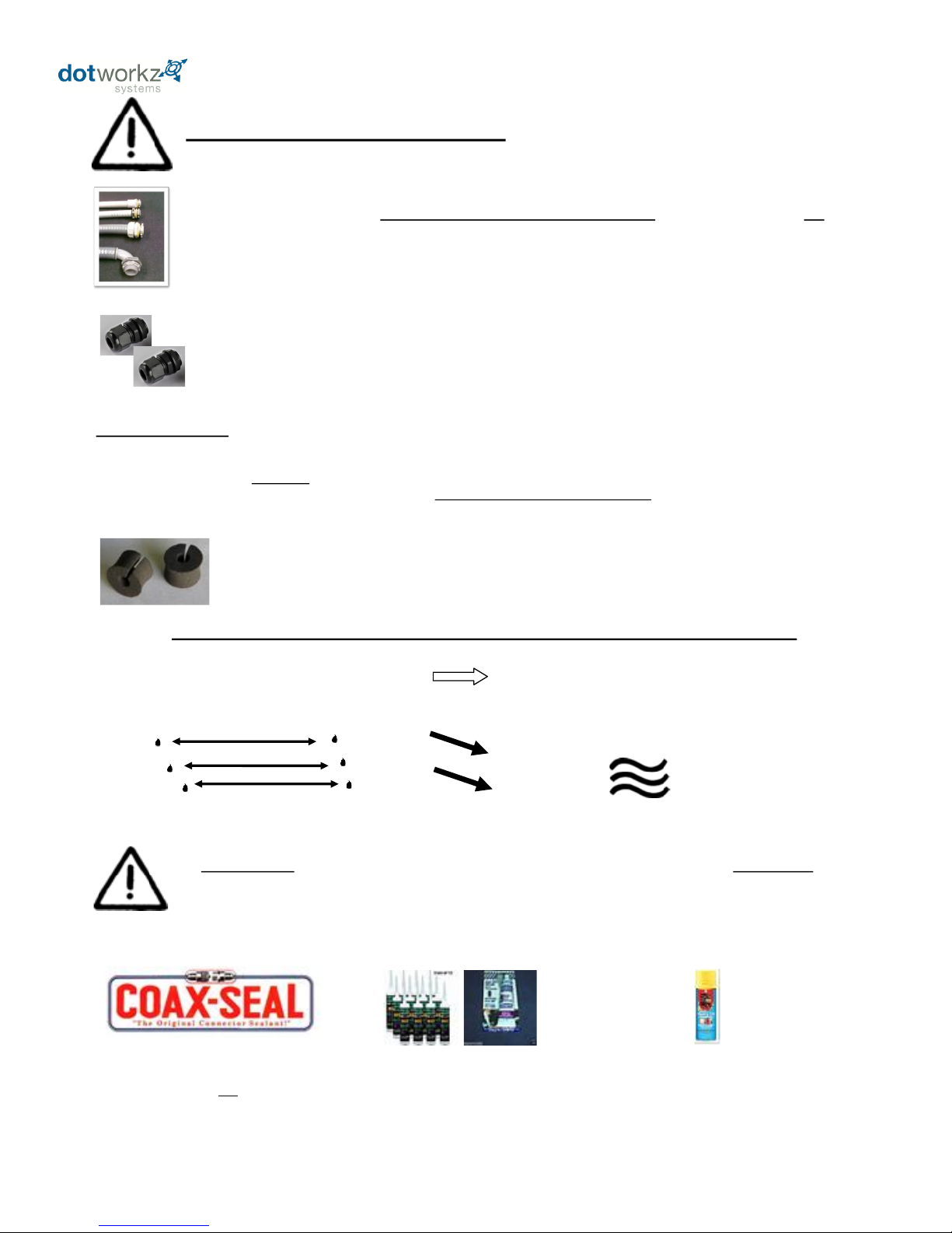
1) If wires, cabling, or conduit are coming at enclosure wire entry level, or above, always create a drip loop.
2) Please use only approved watertight electrical conduit and connectors, IP66 or better, with proper seals and fittings installed & fully seal.
3) Then, after all wire and cables are installed into enclosure, Seal wire entry ports inside of enclosure with any number of commercially
available sealing putty’s, Silicone Sealant, or similar products that are approved by applicable local and relevant electrical codes.
SHOCK HAZARD! Failure to fully seal enclosure wire and cabling entry ports may lead to shock hazard,
unsatisfactory product performance, a possibility of damage to electronics in the Dotworkz enclosure product,
including camera damage, and damage to integrated electronics due to air driven moisture traveling thru the
conduit, condensing and collecting in the enclosure creating a short circuit hazard.
Dotworkz does not endorse, nor has it evaluated any of these products. Test products first, and follow all manufacturers’ instructions.
Follow all applicable electrical and building codes and installation guidelines. End user assumes liability for applicability of these products and
their effectiveness and incurred liability in using these products.
Electrical Conduit Guidelines
For optimal performance, your Dotworkz Enclosure is designed to be Air & Water Tight to eliminate any
moisture, dust, and insect damage, safety, performance, reliability, and maintenance related issues.
Use of Electrical Conduit, without sealing the entry ports/ inside wire feeds within Camera Enclosure, will
subject the inside of your enclosure to possibility of condensation driven moisture, dust, and insect contamination
hazards.
Dotworkz has provided each enclosure with two Cable Gland Strain Relief seal ports that fully seal
enclosure to an IP68 rating, Waterproof and Airtight Seal. To properly seal, only one round cable is used in each
cable gland port. (Holes on enclosure are 7/8” diameter, ready for standard ½” I.D. NPT connector, or PG13 fittings.)
However, we realize our customers are retrofitting these connectors with electrical conduit fittings. We
acknowledge this industry customization and installation practice, and would like to guide customers to properly
install these products.
Humid Air
Condensing to Water
FORCES AT WORK IN ANY UNSEALED, CONDUIT WIRE FEED ENCLOSURE SYSTEM
WARM/MOIST IN UNSEALED CONDUIT MOVES THRU CONDUIT
FEEDS EXPAND & CONTRACT WHEN CONDUIT HEATS & COOLS
WITH OUTSIDE TEMPERATURES
EXPANDING HEATED AIR IS PUSHED INTO ENCLOSURE THEN COOLS &
CONDENSES, HUMID AIR CONDENSES ON SURFACES INSIDE
ENCLOSURE
Electrical Putty & Putty Tapes
Silicone Sealants
Foam Sealants (use very sparingly)
Dotworkz supplies two ½” diameter foam conduit plugs, that when installed, will assist in
sealing off airflow in conduit feed thru, at cable entry inside of enclosure. Putty or Sealant can be
used in conjunction with these plugs, to assure a full seal inside enclosure cable feed entry.
2
Page 6
Foam Conduit Feed Plugs for ½” I.D. (PG-13) Conduit
Prevents Humid Air exchange from venting thru electrical conduit into Dotworkz sealed enclosures,
Thus eliminating condensation issues within Dotworkz sealed enclosures.
QUICK INSTALLATION GUIDE
VENT STOPPER PLUGS for Conduit
1) Pull wires to final installed length.
2) Open Vent Stop Plug and install over wire.
3) Pinch Plug to compress over wire, and insert into
conduit feed mouth.
4) Push plug into conduit mouth with finger
tips till it flush with outside of fitting
5) Repeat steps 1-4 for any other conduit
feeds as needed.
6) To assure an airtight seal, caulk around wires
and cables, coating entire plug surface with sealant.
3
Page 7
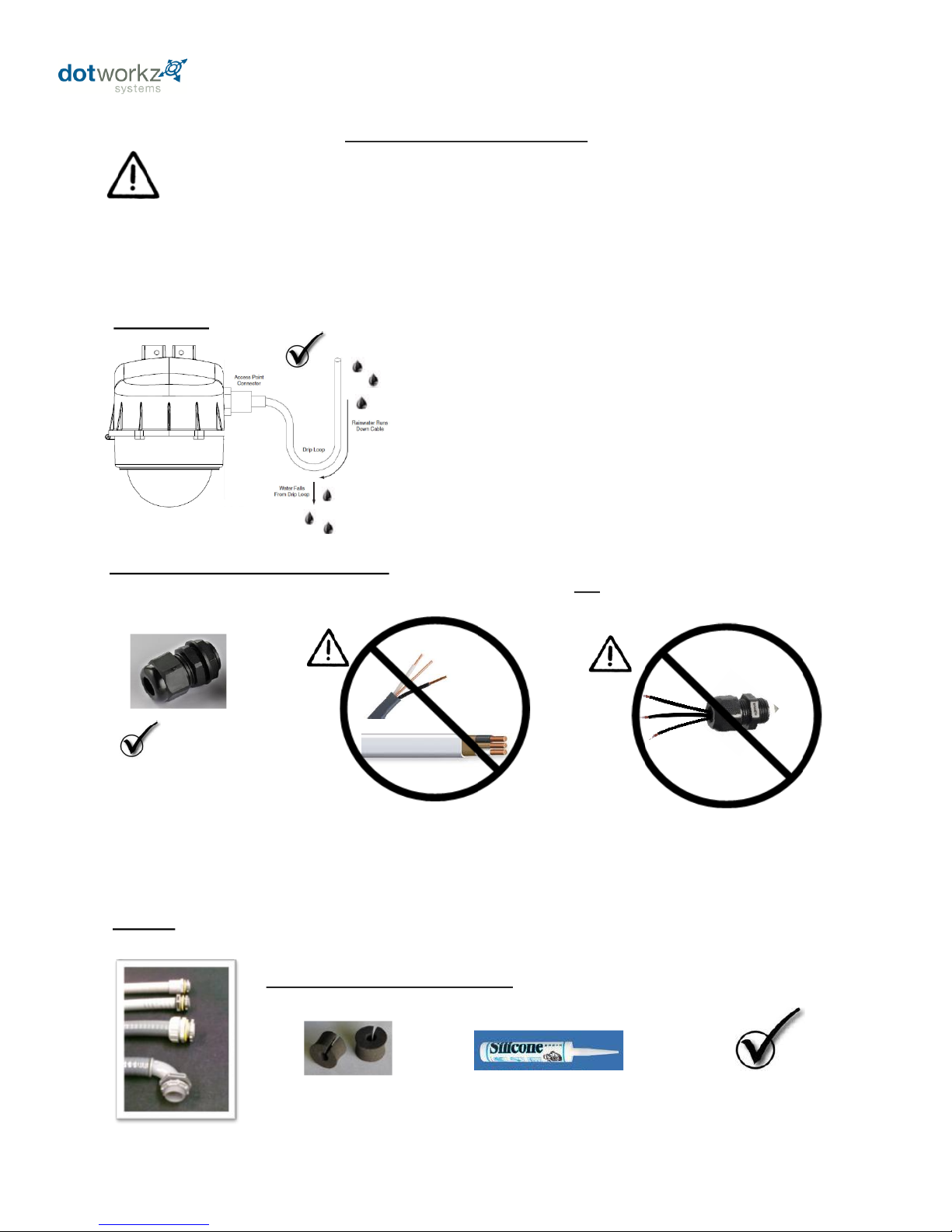
Proper Cable Management to Enclosure
Avoid common Installation Mistakes
Always Create a Drip Loop for all Cables or Conduit Entering
Dotworkz D2 Housing from level or Above D2
Conduit, Power, Data, & Antennae
To avoid gravity driven moisture entry into Enclosure
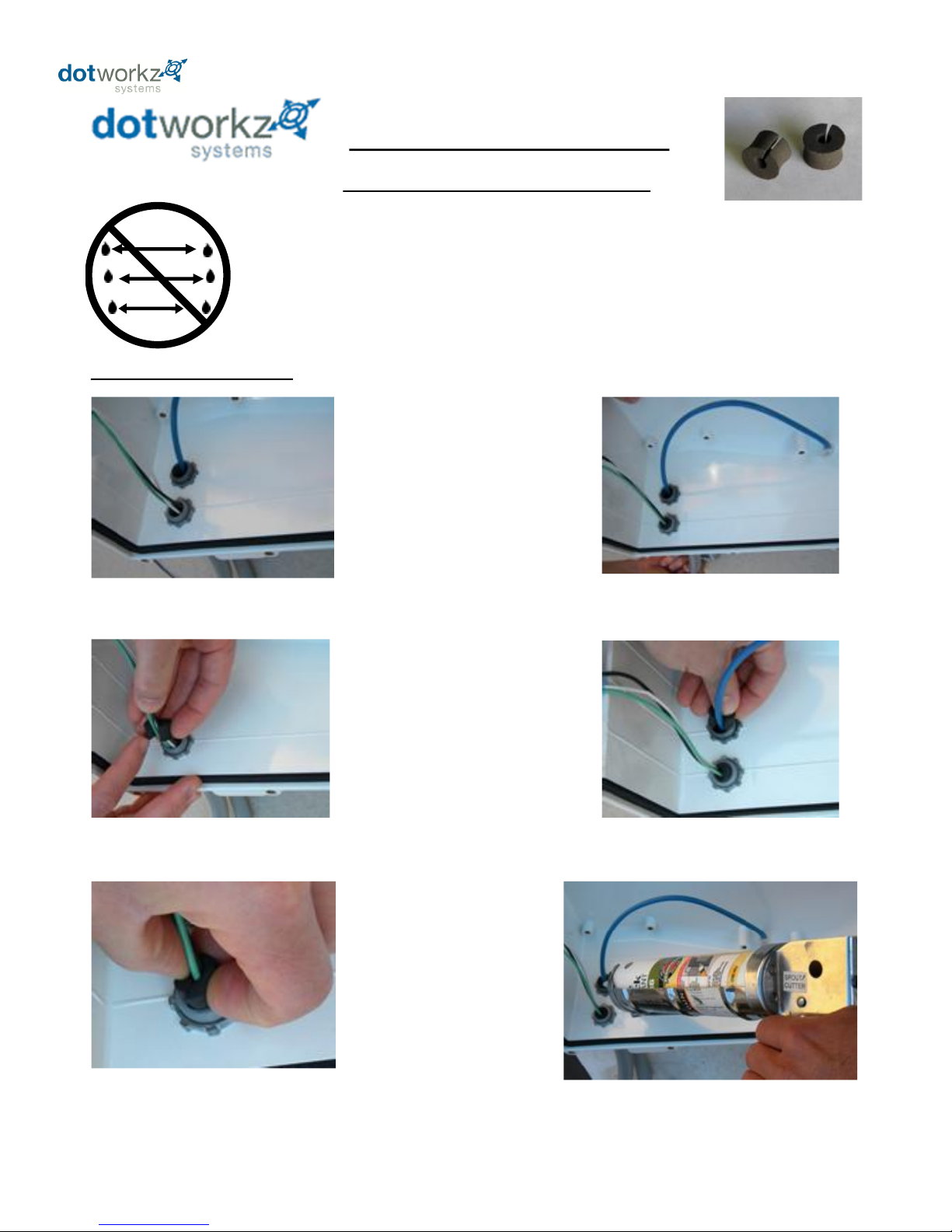
To properly seal, Dotworkz Cable Gland Strain Relief Ports will only accept One single round cable per port
NO
Romex
Flat Cable
* SJOOW
* Cat5/ Cat6
* Coaxial
+
=
Dotworkz Standard Cable Gland Port
Seals are designed for ONE single round
cable only per port
Use Round Cable Only with
provide Cable Gland Port Seal
Only Use Qualified Installation or Service Technician for Installing & Servicing Dotworkz Enclosures.
Power Must be disconnected and kept off while installing or Servicing Enclosure.
Follow All Local and Applicable Electrical Codes and Standards for Installation of Electrical components.
All Cable Ports, wire feeds, or Conduit must be fully sealed to eliminate moisture within Enclosure.
All Dotworkz Enclosures are required to be fully sealed before placing into service, to protect integrated products, to
eliminate any moisture driven shock hazard, to perform optimally as designed.
DRIP LOOPS
Cable can be multi-conductor in single round cable bundle such as Cat5/ 6e (burial rated), or Conductor cable SJ00W (water rated)
Cable Gland Strain Relief Port Seals
Conduit
+
If Conduit is used in Lieu of Cable Gland Port Seals provided,
Then Use Only Liquid Tight Conduit & fittings properly sealed.
Internal Wire feeds must be fully sealed prior to placing Enclosure into Service.
See Conduit Guidelines section of this manual.
4
Page 8
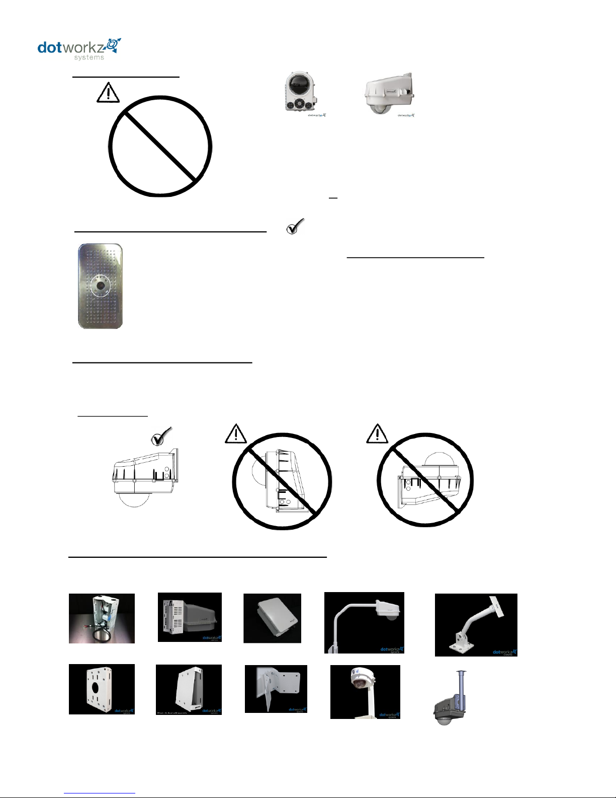
Dotworkz D2 Seals & drip edges are engineered for horizontal installation Only: Dome bubble faces down.
Vertical and dome-up installations are not advised, and will be prone to moisture incursion within housing, and
will void warranty.
Dotworkz D2 Mounting Guidelines
COOLDOME™ Wiring
Dotworkz D2-CD Operates using low voltage only, and
creates ample currents when cooler is engaged.
Follow relevant Cable Gauge Guidelines provide in this
document applicable to your product model.
Dedicated 12 VDC or 24 VDC models
Dotworkz Humidity Removal Canister
Dotworkz Provides a Humidity Removal Canister must be installed into COOLDOME prior to entering
enclosure into service.
Active Cooler within COOLDOME lowers temperature to at or near dew point within D2
COOLDOME, so trapped air must be dried out to eliminate condensation issues. The sealed air is
efficiently dried out by this desiccant canister, which provides a color coded saturation state window.
It must be removed from its foil envelope, and can be installed on shelf next to cooler, or
above camera on camera mounting plate. See installation section for service info on this product.
D2 & COOLDOME™ Accessories & Mount Options
Your D2 COOLDOME is wall mount ready, but can be Installed with a number of Dotworkz Optional Mounts (sold separately)
NO
18 gg
BR-ECB1
BR-PSA1
BR-CNR1
NM-CDPS NEMA for
CD Power Supply
KT-CDR2 Outdoor CD Power Pole Mount Kit
BR-MPM1
BR-MPM1-AC
BR-APM1
BR-MPM1
With common
Pipe anchor for
pendant mounting
5
Page 9
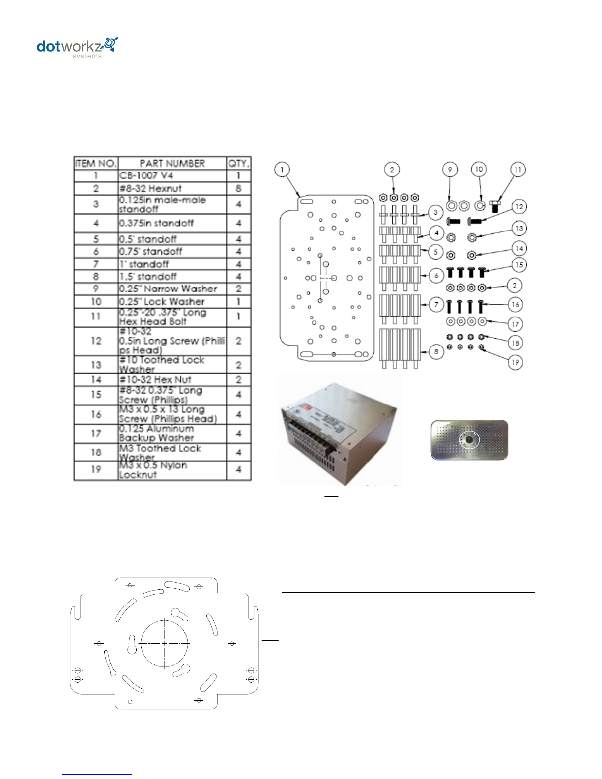
Optional BR-AXBR Camera Mount Bracket for Larger Cameras
(Request BR-AXBR at time of order for listed camera models)
Optional BR-AXBR Bracket Direct Compatibility:
(Available by special order)
Axis 231D, & 232D
DVTel 9840
Merit-LiLin PIH-7000/7600/7625
PiXORD P-463T Fast Speed Dome
Pelco Spectra IV
Sony SNCRH124, SNC-RS44N, SNC-RS46N
Toshiba IK-DP30A
Component Check List
Included Standard Hardware for Camera Mounting
& Provided COOLDOME Accessories
KT-HRC1
Humidity Removal Canister
S-250-12V or S-250-24V
Step Down Power Supply
6
Page 10
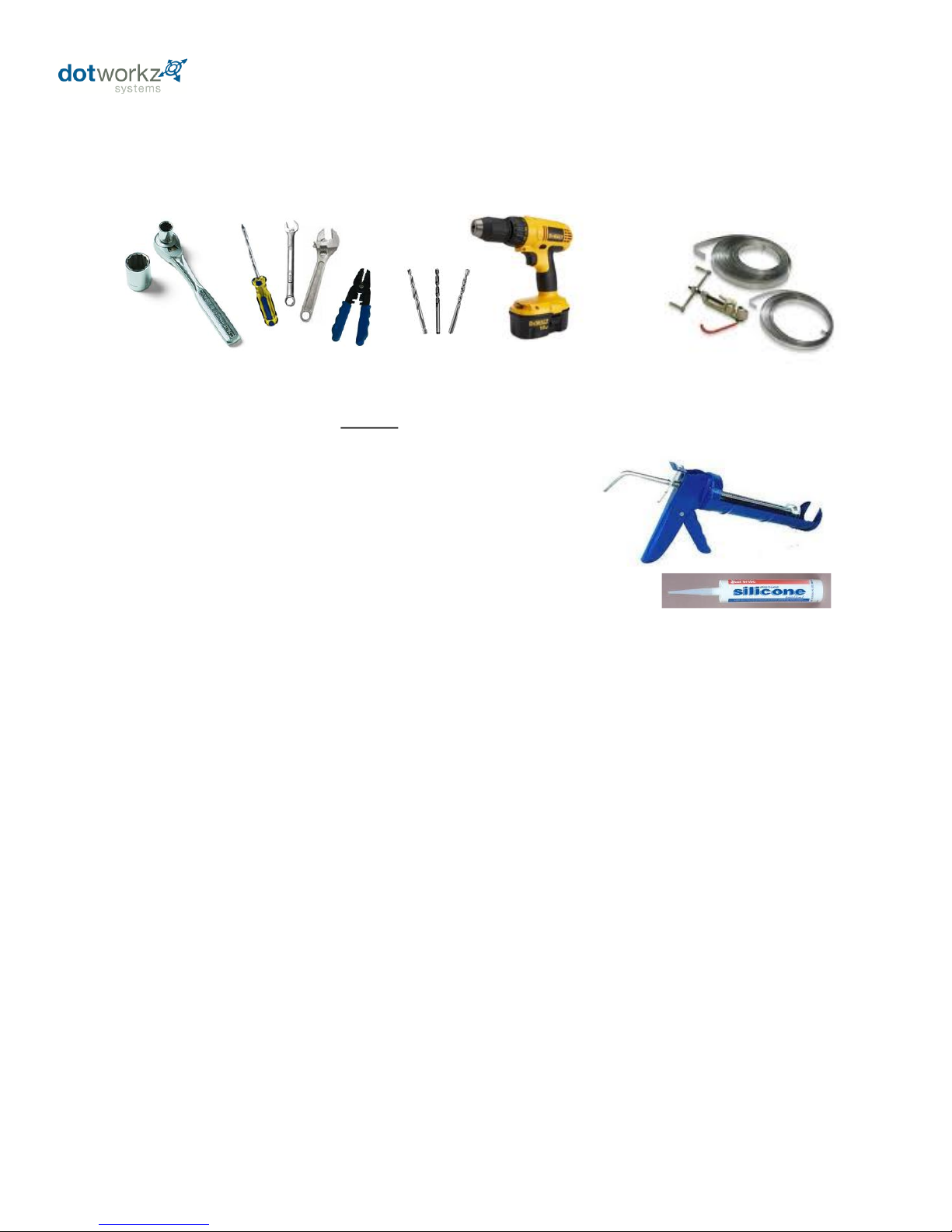
- #1 & #2 Phillips head screw driver
-#1 Flat Blade screw driver or smaller
- 3/8 Socket wrench, nut driver, or adjustable wrench
- 5/16 Socket wrench, nut driver, or adjustable wrench
- 7/16 Socket wrench, nut driver, or adjustable wrench
- 7/32 Socket wrench, nut driver, or adjustable wrench
- 11/32 Socket wrench, nut driver, or adjustable wrench
- Wire stripping tool
- Caulk Gun & Silicone Sealant
Tools Recommended for Enclosure & Camera Mounting
Pole Strapping Tools
Drill & Bits
For Wall Mounting
- Drill and Bits for user supplied fasteners for wall mounting enclosure
For Pole Mounting
- Strapping / Banding Tools for user supplied Stainless Steel Pole Straps
For other needed Mounting Styles:
**See Dotworkz for Available Optional Mounting Brackets for a wide selection of Enclosure
Mounting Styles @ www.dotworkz.com, or ask your favorite distributor or Sales Associate, or call
Dotworkz Support (866) 575-4689
Dotworkz D2 COOLDOME accepts four (4) 3/8" Bolts or Lag Screws to Wall Mount
See Mounting Template at back of this manual for hole pattern.
(Customer provides enclosure mounting hardware)
Hand Tools
7
Page 11
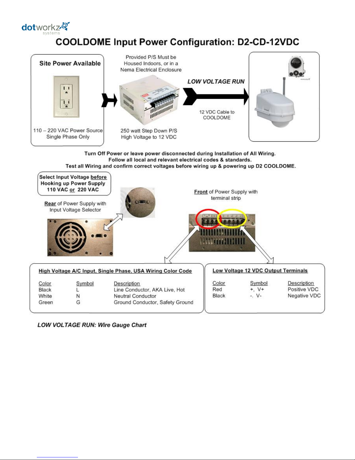
Low Voltage Line Drop Wire Gauge Tables
See 12 VDC & 24 VDC Wire Gage Selector Charts – Next Page
8
Page 12
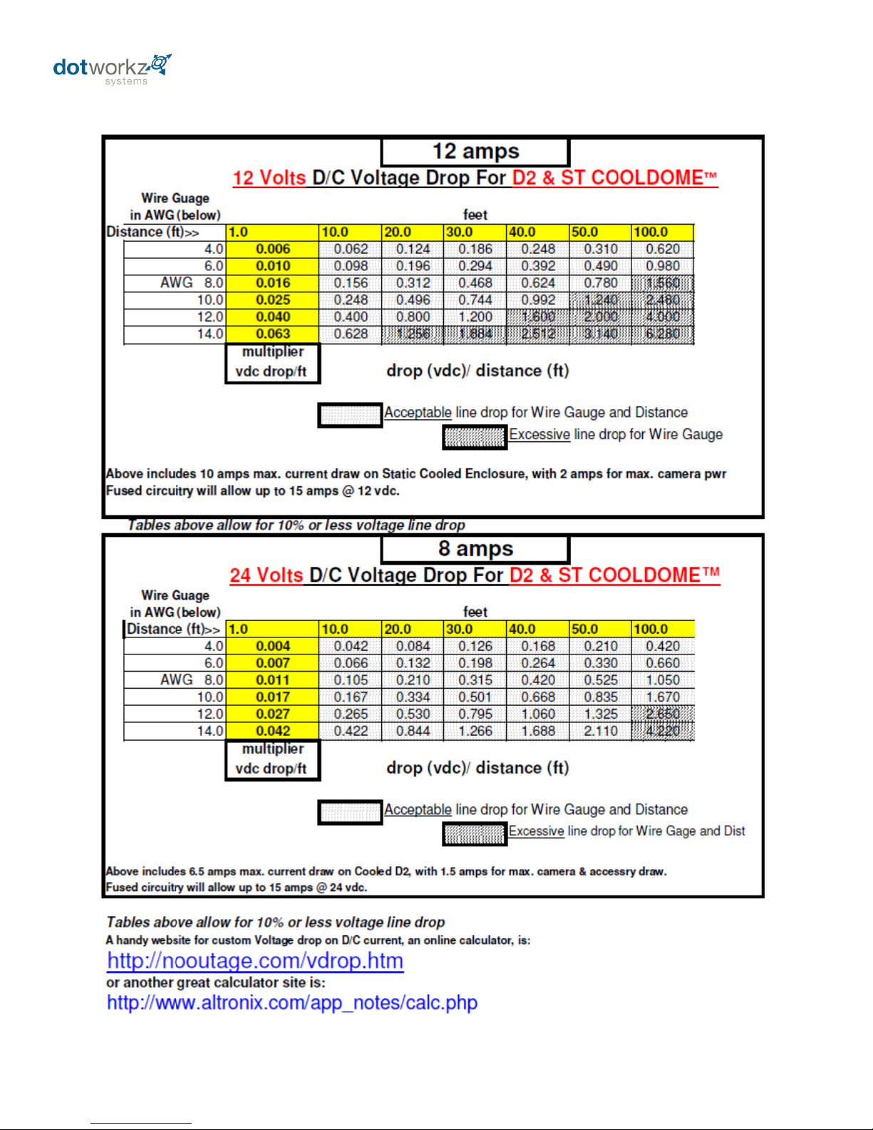
Wire Gage Selector Charts
9
Page 13
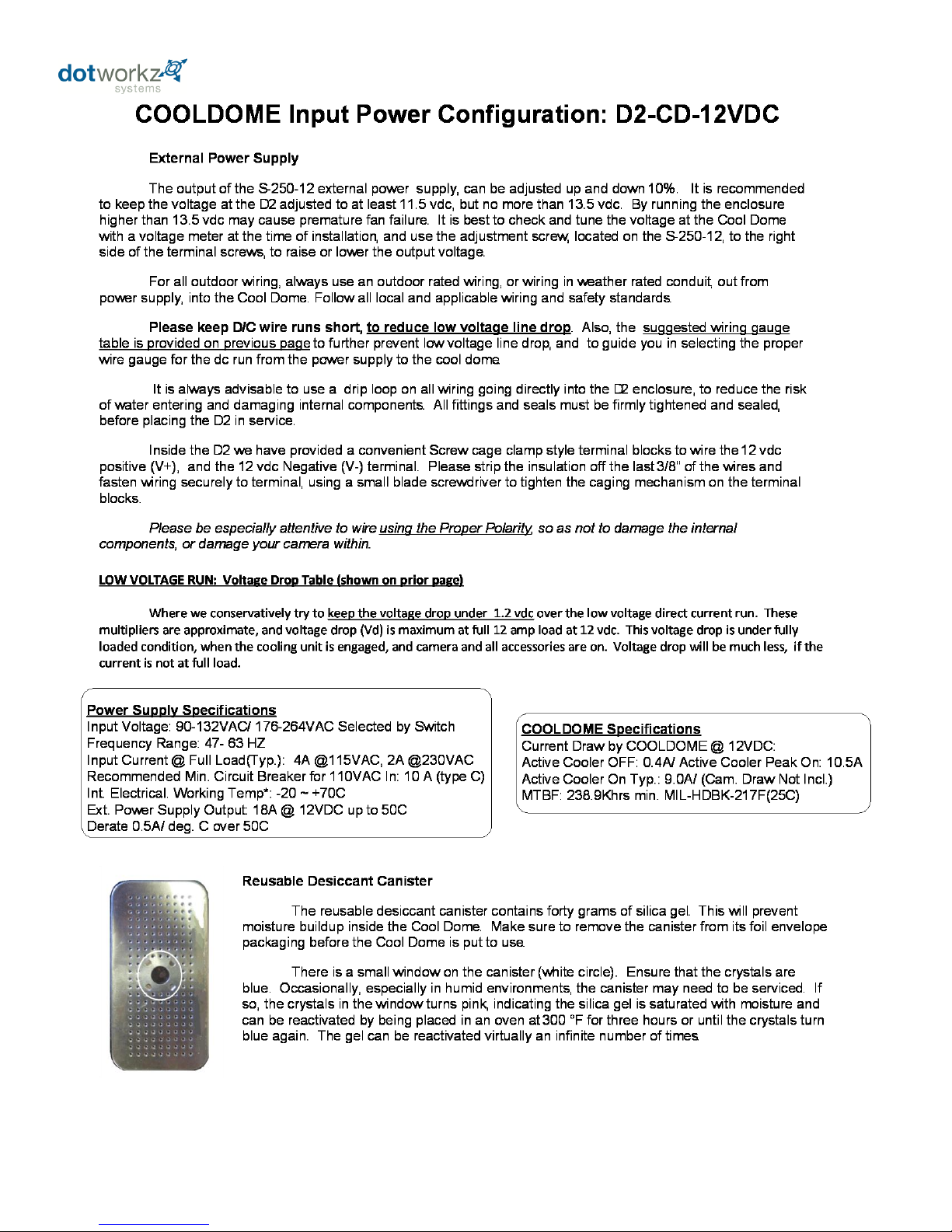
10
Page 14
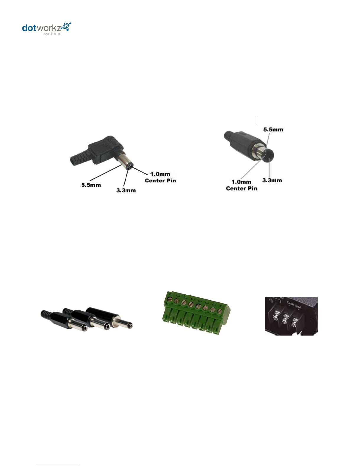
All D2 environmental enclosures come standard with a 12VDC Right Angle Barrel Plug (3.3mm x 5.5mm
with a 1mm center pin) for majority of the IP cameras on the market.
Camera Power Setup
(STANDARD 12VDC CONNECTOR)
Right Angle Standard
Inline version
All D2 environmental enclosures come standard with a 12VDC Right Angle Barrel Plug (3.3mm x 5.5mm
with a 1mm center pin) for majority of the IP cameras on the market.
Camera Power Setup
(STANDARD 12VDC CONNECTOR)
Right Angle Standard
Inline version
If you IP camera’s power connector is different but still accepts up to ~ 13VDC for power, please see our
section on Camera Power Setup (NON-STANDARD CONNECTOR) for instructions on how to power
your camera. Below are pictures of typical NON-STANDARD CONNECTORS.
DC plugs with NO center pin
Terminal pin connectors
Terminal connector
Provided 12 VDC camera power connector can be cut-off & Stripped, using Dotworkz cable as a jumper
to install a non-standard power terminal connector, such as any shown below.
For Non-Standard Connector Plugs, consult camera supplier or online, if it is not supplied with your
camera model.
Camera Power Connection
The D2-CD-12V provides an 18” lead from the COOLDOME power circuit with the following common 12 VDC Barrel
connector, which is nearly and industry standard. Dotworkz provides the Right Angle version below.
The D2-CD-24V offers a simple DC jumper cable to connect camera power to the 24 VDC COOLDOME circuits.
11
Page 15
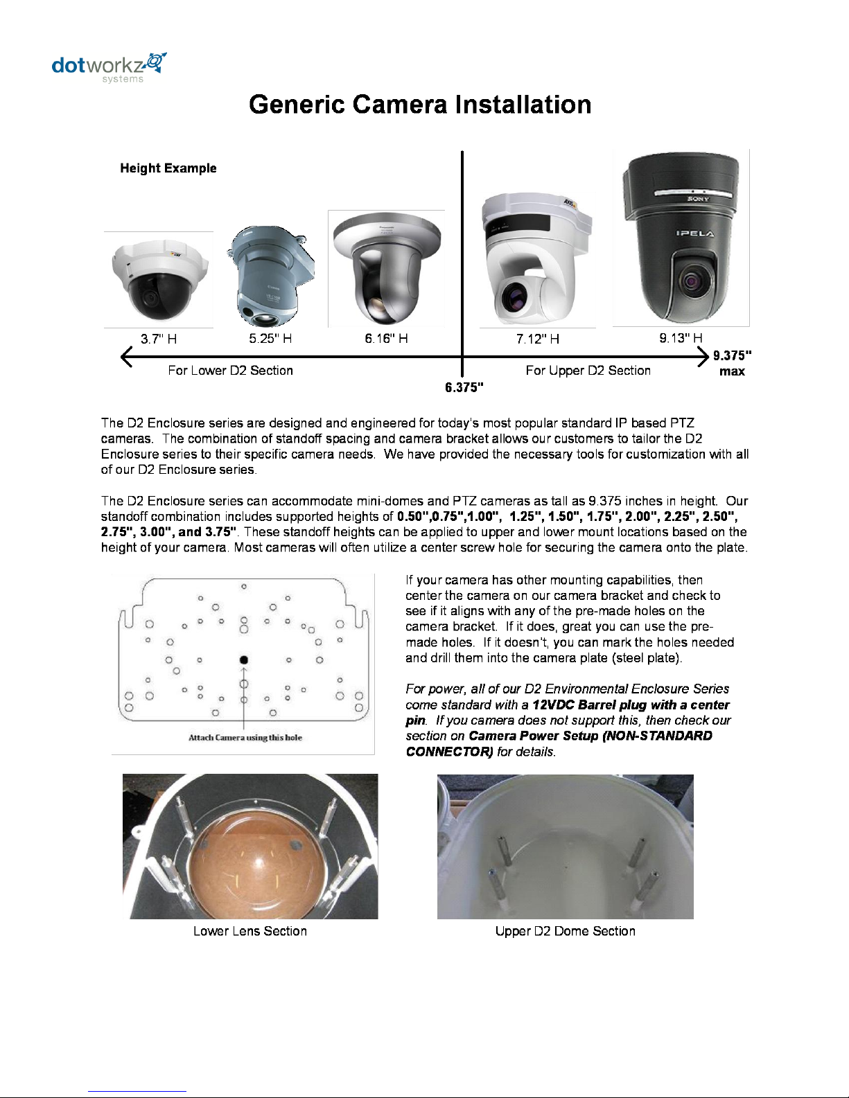
12
Page 16
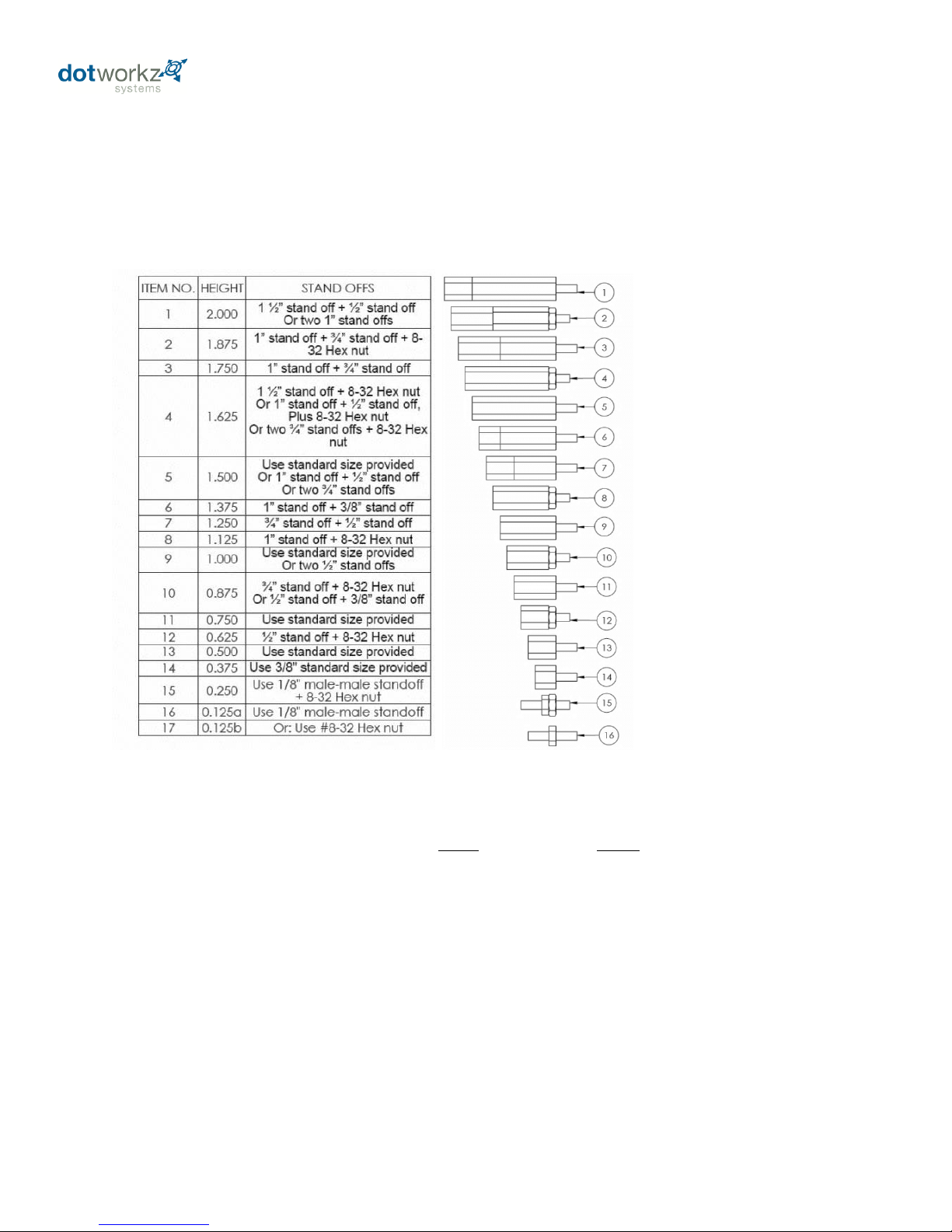
Stand Off Assembly Key for Camera Height Adjustment
Camera mount stand offs can be adjusted to any height from 0” to 3.75” using assembly logic illustrated above.
By utilizing both the camera mounts inside the D2; the upper mounts, and the lower mounts around the lens on hinged
lower of D2, virtually any PTZ or Mini-Dome Camera can be mounted into the enclosure at any level. It is best to utilize a
mounting strategy that uses the least amount of stand offs, by utilizing the camera mounts inside the D2 that are closest
to optimal camera height for stability reasons.
13
Page 17
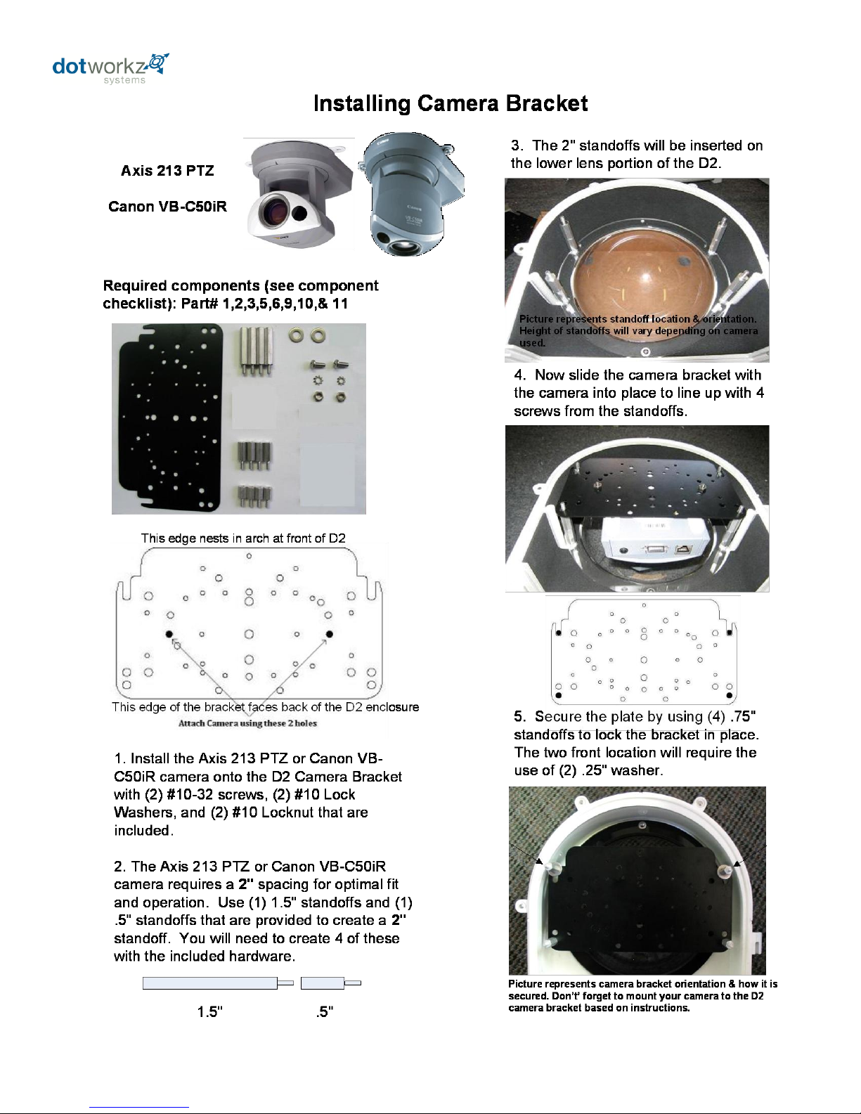
14
Page 18
Installing Camera Bracket
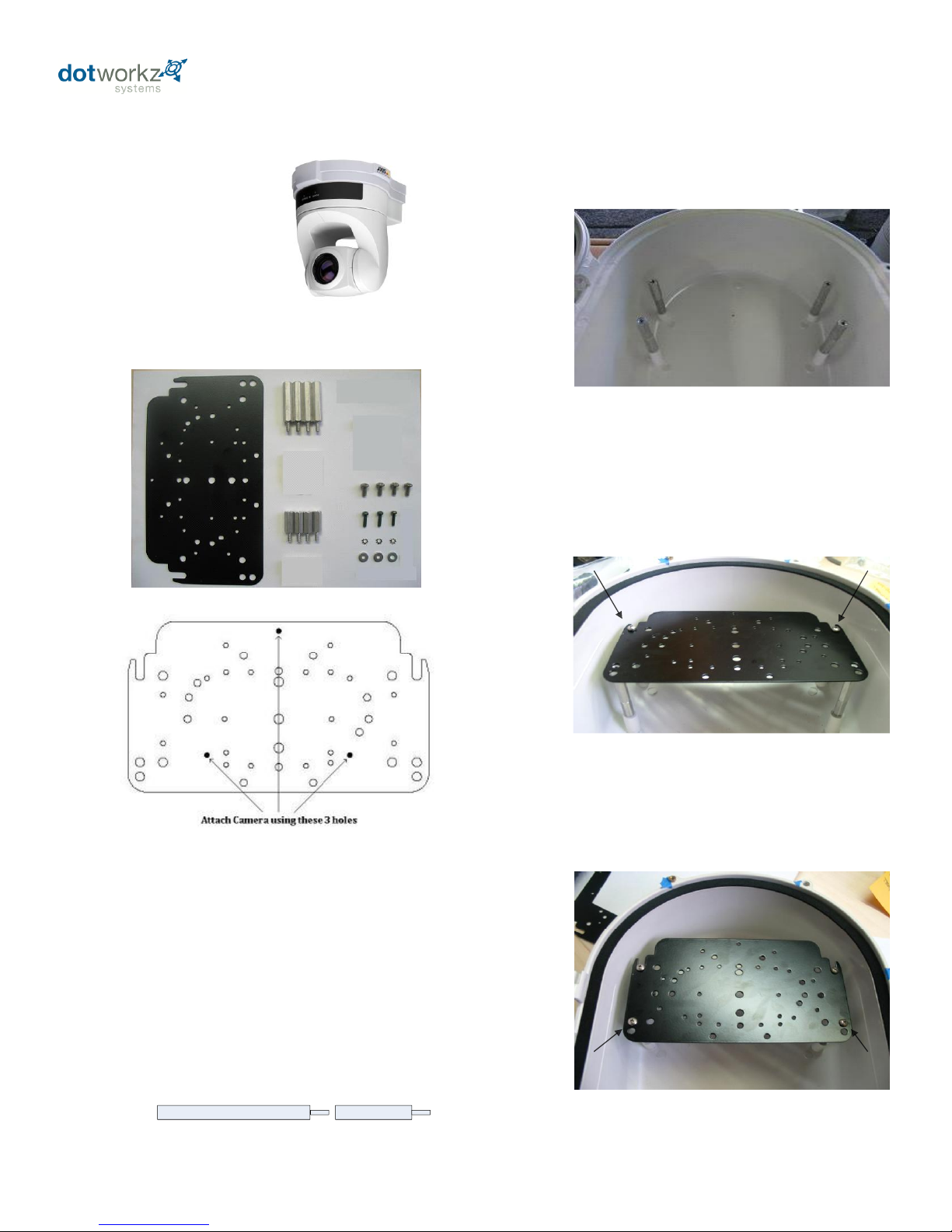
Axis 214 PTZ
1. Install the Axis 214 PTZ camera onto the
D2 Camera Bracket with (3) m3-.5 screws,
(3) m3 external lock washers, and (3) m3 1/8"
washer that are included.
2. The Axis 214 PTZ camera requires a 2.25"
spacing for optimal fit and operation. Use (1)
1.5" standoffs and (1) .75" standoffs that are
provided to create a 2.25" standoff. You will
need to create 4 of these with the included
hardware.
Required components (see component
checklist): Part # 1,3,5,12,14,15,& 16
3. The 2.25" standoffs will be inserted
on the upper portion of the D2.
1.5"
.75"
4. Now slide the camera bracket with
the camera into place to line up with 4
screws holes from the standoffs.
5. Use (4) #8-32 screws (Phillips head)
to secure the bracket into place.
Again, make sure the camera
bracket is facing the right
direction.
This edge nests in arch at front of D2
This edge of the bracket faces back of the D2 enclosure
Tip: Insert (2) #8-32 screws in the front two
standoffs to provide a guide to slide the
camera bracket into. The last two corner
holes should line up and be secured last.
Picture represents camera bracket orientation & how it is
secured. Don’t’ forget to mount your camera to the D2
camera bracket based on instructions.
Picture represents standoff location & orientation. Height
of standoffs will vary depending on camera used.
15
Page 19
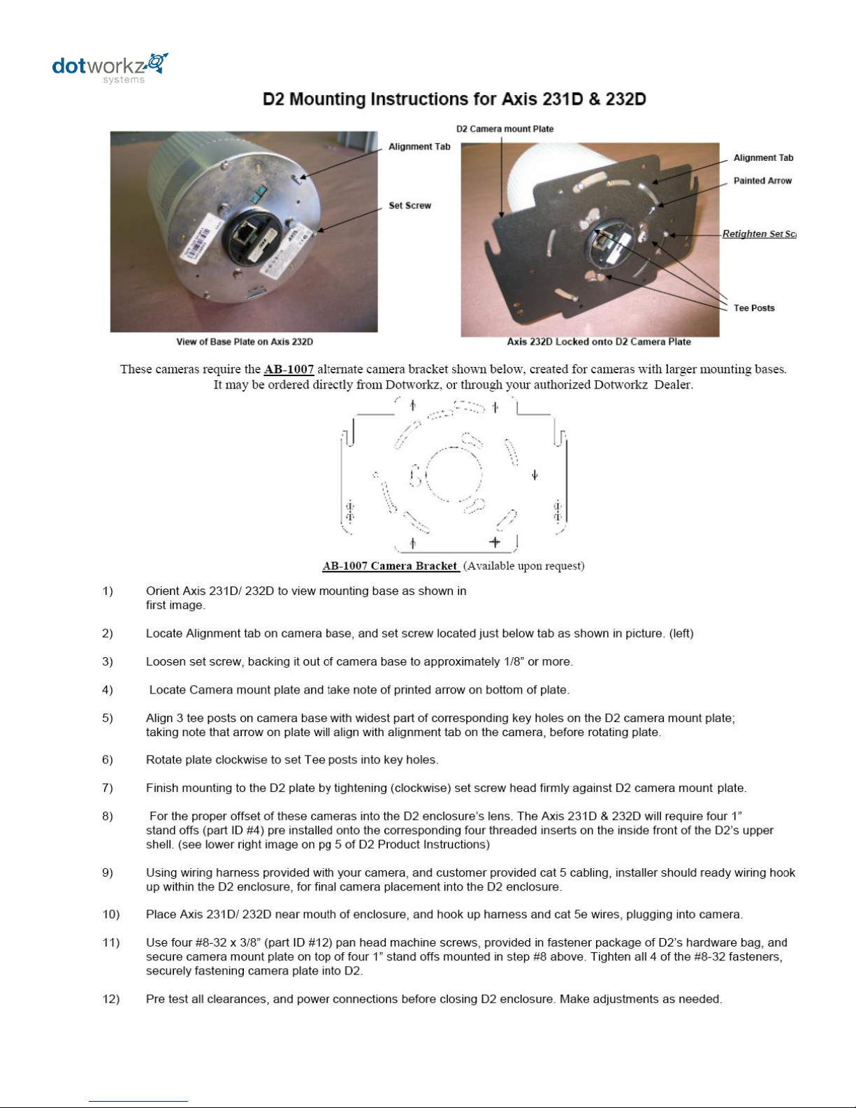
16
Page 20
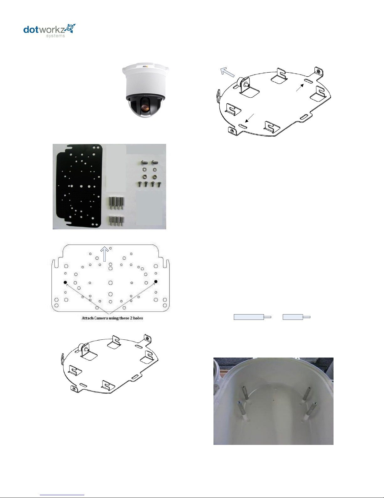
Installing Camera Bracket
Axis 233D PTZ
2. Do this by aligning the two holes on the D2
camera bracket with the Axis ceiling bracket
adapter. Use (2) #10-32 ½” long screws, (2)
#10 lock washers, and (2) #10-32 hex nuts
that are included to secure the axis ceiling
adapter to the D2 camera bracket.
Required components (see component
checklist): Part # 1,2,3,9,10,11,& 12
5. The 1.25" standoffs will be inserted on
the upper portion of the D2.
.5"
.75"
This edge nests in arch at front of D2
This edge of the bracket faces back of the D2 enclosure
Axis 233D Ceiling bracket that came
with the camera. *This is a required
item for installation*
Align these 2
holes with the
D2 bracket
holes for the
Axis 233D
4. The Axis 233D PTZ camera requires a
1.25" spacing for optimal fit and operation.
Use (1) .75" standoffs and (1) .5" standoffs
that are provided to create a 1.25" standoff.
You will need to create 4 of these with the
included hardware.
1. To install the Axis 233D in the D2
Enclosure we must first install the Axis 233D
ceiling bracket adapter that came with the
camera onto the D2 camera mounting plate.
Axis 233D Ceiling bracket that came with the camera.
*This is a required item for installation*
3. Next follow the Axis 233D installation
instruction to secure the camera to the ceiling
bracket adapter that is now attached to the
D2 Camera Bracket.
Picture represents standoff location & orientation.
Height of standoffs will vary depending on camera used.
17
Page 21
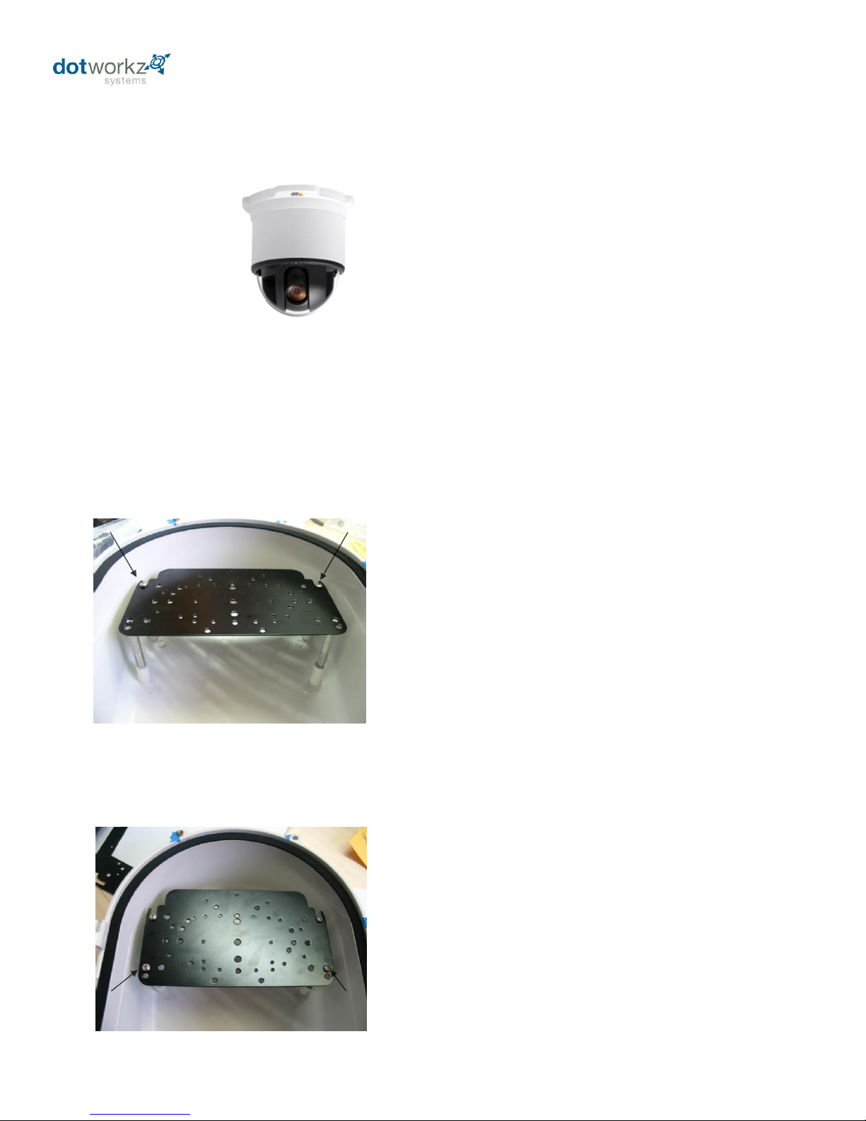
Installing Camera Bracket
Axis 233D PTZ
6. Now slide the camera bracket with the
camera into place to line up with 4 screws
holes from the standoffs.
7. Use (4) #8-32 screws (Phillips head) to
secure the bracket into place.
Tip: Insert (2) #8-32 screws in the front two
standoffs to provide a guide to slide the
camera bracket into. The last two corner
holes should line up and be secured last.
Continued . . . . . . . .
Again, make sure the camera
bracket is facing the right
direction.
Picture represents camera bracket orientation & how it is
secured. Don’t’ forget to mount your camera to the D2
camera bracket based on instructions.
Picture represents standoff location & camera
bracket orientation. Height of standoffs will vary
depending on camera used.
18
Page 22
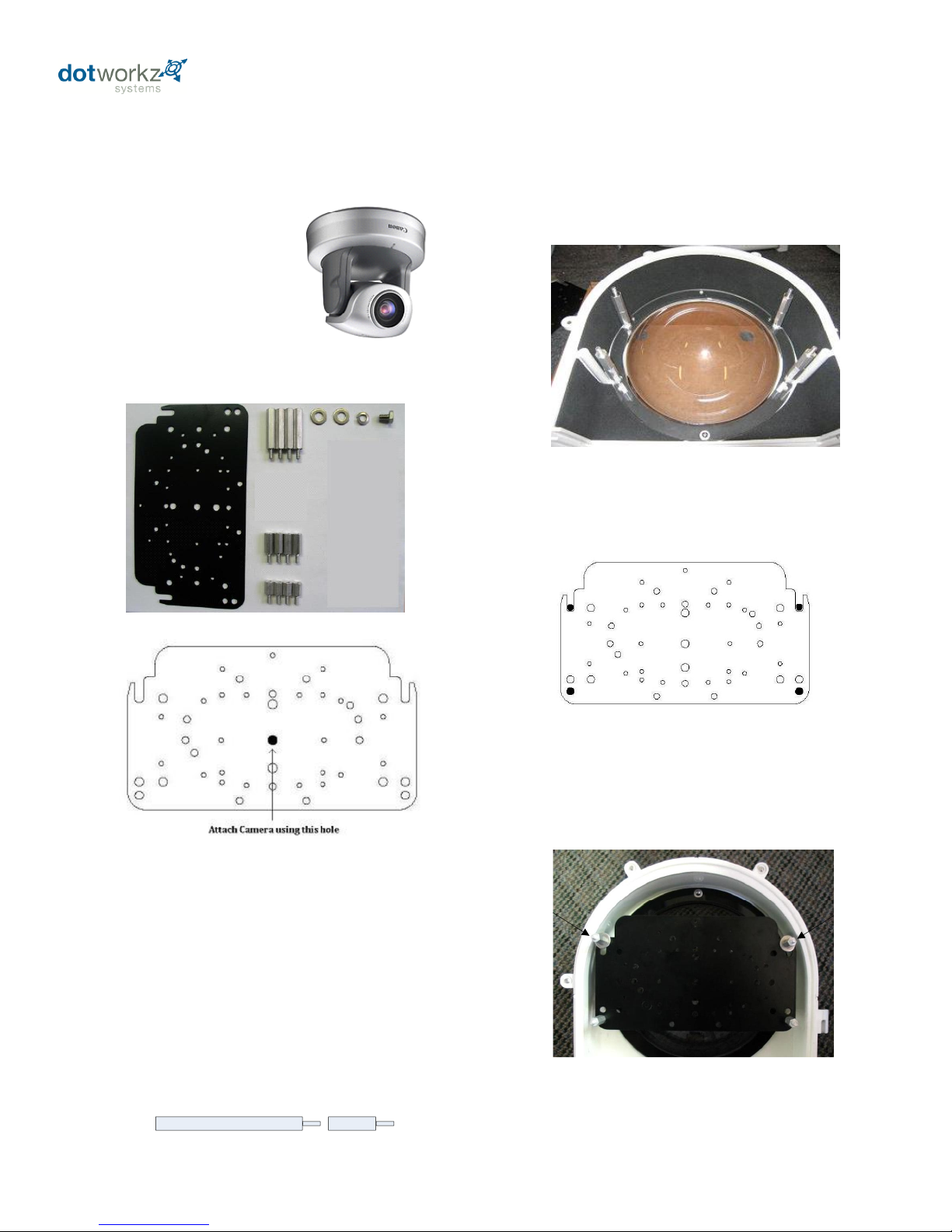
Installing Camera Bracket
Canon VB-C300
1. Install the Canon VB-C300 camera onto
the D2 Camera Bracket center hole with (1)
.25"-20 3/8" Long Bolt, and (1) .25" Lock
Washer that are included.
2. The Canon VB-C300 camera requires a 2"
spacing for optimal fit and operation. Use (1)
1.5" standoffs and (1) .5" standoffs that are
provided to create a 2" standoff. You will
need to create 4 of these with the included
hardware.
Required components (see component
checklist): Part# 1,2,3,5,6,7,& 8
3. The 2" standoffs will be inserted on the
lower lens portion of the D2.
1.5"
.5"
4. Now slide the camera bracket with the
camera into place to line up with 4 screws
from the standoffs.
5. Secure the plate by using (4) .75"
standoffs to lock the bracket in place. The
two front location will require the use of (2)
.25" washer.
This edge nests in arch at front of D2
This edge of the bracket faces back of the D2 enclosure
Picture represents standoff location & orientation.
Height of standoffs will vary depending on camera used.
Picture represents camera bracket orientation & how it is
secured. Don’t’ forget to mount your camera to the D2
camera bracket based on instructions.
19
Page 23
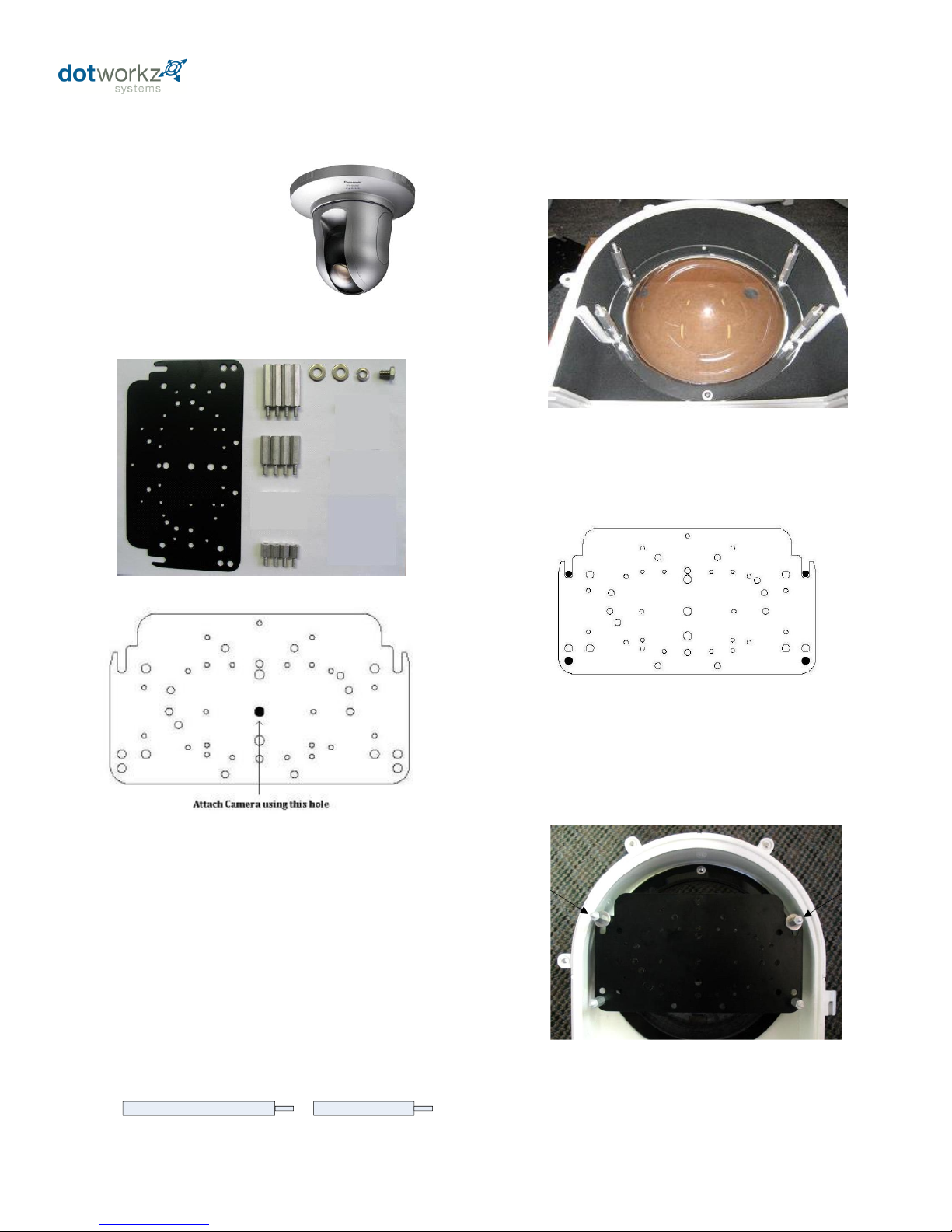
Installing Camera Bracket
Panasonic NS-202
1. Install the Panasonic NS-202 camera onto
the D2 Camera Bracket center hole with (1)
.25"-20 3/8" Long Bolt, and (1) .25" Lock
Washer that are included.
2. The Panasonic NS-202 camera requires a
2.5" spacing for optimal fit and operation.
Use (1) 1.5" standoff and (1) 1.0" standoff
that are provided to create a 2.5" standoff.
You will need to create 4 of these with the
included hardware.
Required components (see component
checklist): Part# 1,2,4,5,6,7,& 8
3. The 2.5" standoffs will be inserted on
the lower lens portion of the D2.
1.5"
1.0"
4. Now slide the camera bracket with the
camera into place to line up with 4 screws
from the standoffs.
5. Secure the plate by using (4) .5"
standoffs to lock the bracket in place. The
two front location will require the use of (2)
.25" washer.
This edge nests in arch at front of D2
This edge of the bracket faces back of the D2 enclosure
Picture represents standoff location & orientation.
Height of standoffs will vary depending on camera used.
Picture represents camera bracket orientation & how it is
secured. Don’t’ forget to mount your camera to the D2
camera bracket based on instructions.
20
Page 24
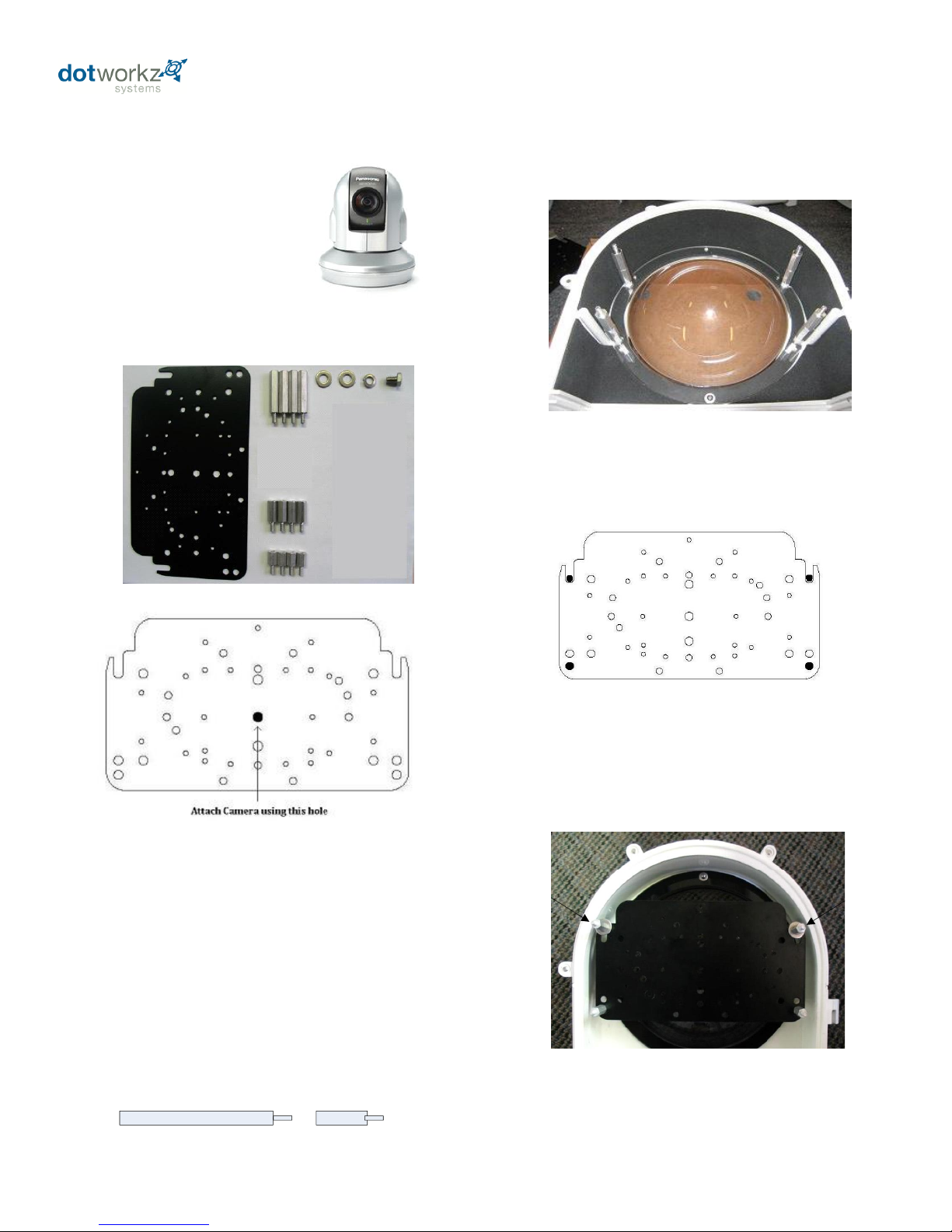
Installing Camera Bracket
Panasonic BB-HCM381/
580/581 & KX-HMC280
1. Install the Panasonic camera onto the D2
Camera Bracket center hole with (1) .25"-20
3/8" Long Bolt, and (1) .25" Lock Washer that
are included.
2. The Panasonic camera requires a 2.0"
spacing for optimal fit and operation. Use (1)
1.5" standoff and (1) .5" standoff that are
provided to create a 2.0" standoff. You will
need to create 4 of these with the included
hardware.
Required components (see component
checklist): Part# 1,2,3,5,6,7,& 8
3. The 2.0" standoffs will be inserted on
the lower lens portion of the D2.
1.5"
.5"
4. Now slide the camera bracket with the
camera into place to line up with 4 screws
from the standoffs.
5. Secure the plate by using (4) .75"
standoffs to lock the bracket in place. The
two front location will require the use of (2)
.25" washer.
This edge nests in arch at front of D2
This edge of the bracket faces back of the D2 enclosure
Picture represents standoff location & orientation.
Height of standoffs will vary depending on camera used.
Picture represents camera bracket orientation & how it is
secured. Don’t’ forget to mount your camera to the D2
camera bracket based on instructions.
21
Page 25
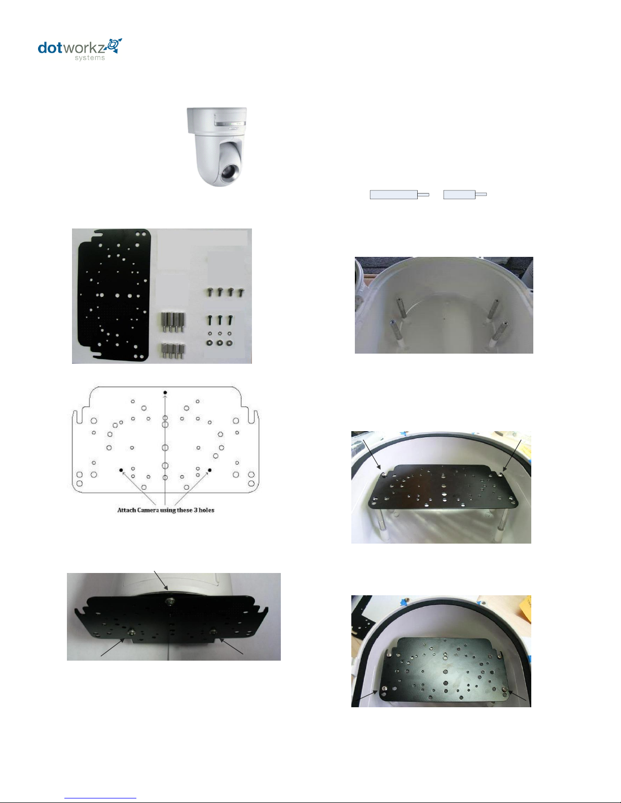
Installing Camera Bracket
Sony RZ25N
1. Install the Sony RZ25N camera onto the
D2 Camera Bracket with (3) m3-.5 ½” Long
screw (3) m3 External Lock Washer, and (3)
m3 1/8" Washer that are included.
Required components (see component
checklist): Part # 1,2,3,12,14,15,& 16
2. The Sony RZ25N camera requires a 1.25"
spacing for optimal fit and operation. Use (1) .75"
standoffs and (1) .5" standoffs that are provided to
create a 1.25" standoff. You will need to create 4
of these with the included hardware.
.5"
.75'
4. Now slide the camera bracket with the camera
into place to line up with 4 screws holes from the
standoffs.
5. Use (4) #8-32 screws (Phillips head) to secure
the bracket into place.
Again, make sure the camera
bracket is facing the right direction.
This edge nests in arch at front of D2
This edge of the bracket faces back of the D2 enclosure
Tip: Insert (2) #8-32 screws in the front two
standoffs to provide a guide to slide the camera
bracket into. The last two corner holes should
line up and be secured last.
3. The 1.25" standoffs will be inserted on the
upper portion of the D2.
Tip: Don not screw all the way through.
Screw them in enough to catch some thread
on all three screw locations. Once all three
screw catch enough thread, begin tightening
one at a time.
Picture represents camera bracket orientation & how it is secured.
Don’t’ forget to mount your camera to the D2 camera bracket
based on instructions.
Picture represents standoff location & orientation.
Height of standoffs will vary depending on camera
used.
22
Page 26
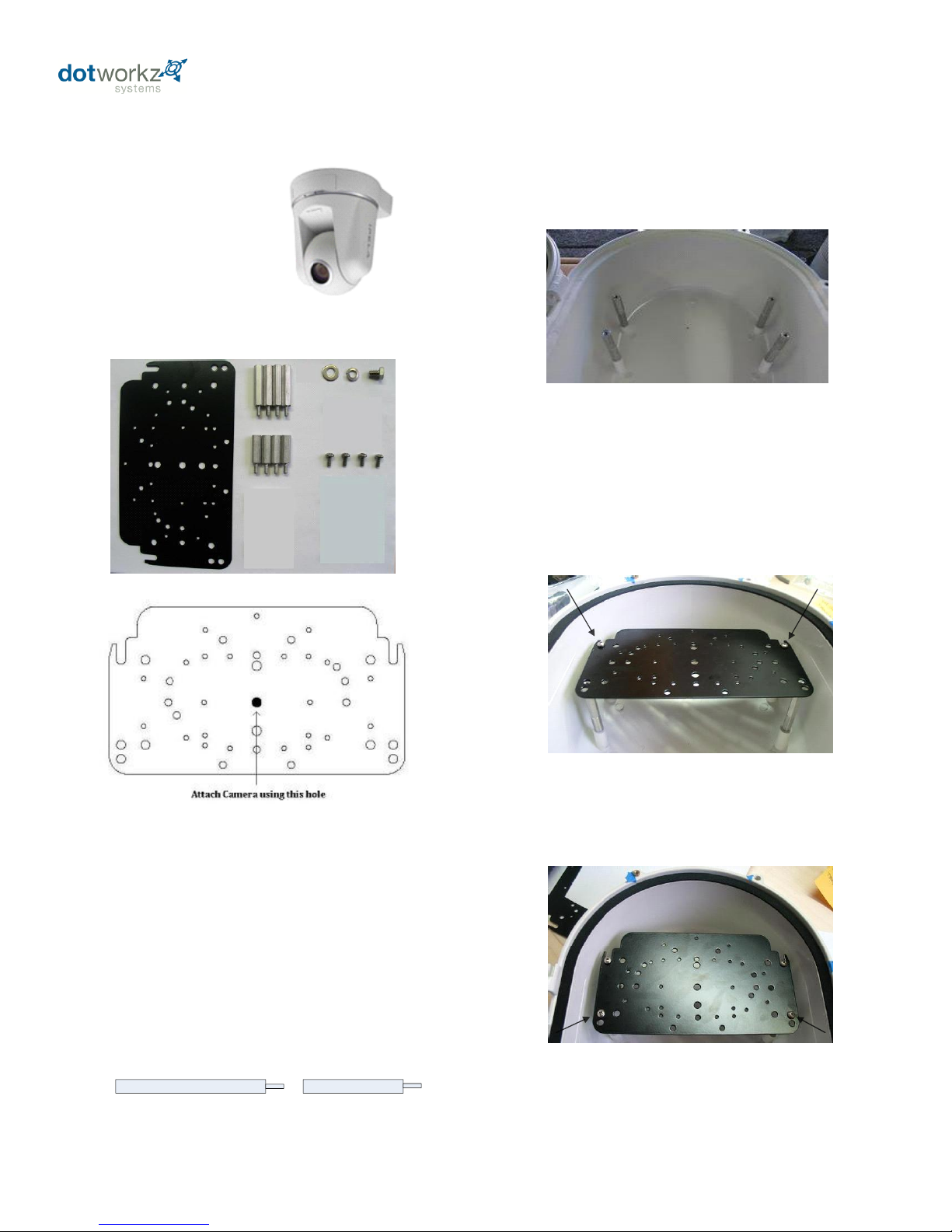
Installing Camera Bracket
Sony RZ50N
1. Install the Sony RZ50N camera onto the
D2 Camera Bracket center hole with (1) .25"20 3/8" Long Bolt, (1) .25" Lock Washer, and
(1) .25" Washer that are included.
Required components (see component
checklist): Part # 1,4,5,6,7,8,& 12
4. Now slide the camera bracket with the
camera into place to line up with 4 screws
holes from the standoffs.
5. Use (4) #8-32 screws (Phillips head) to
secure the bracket into place.
Again, make sure the camera
bracket is facing the right direction.
This edge nests in arch at front of D2
This edge of the bracket faces back of the D2 enclosure
Tip: Insert (2) #8-32 screws in the front two
standoffs to provide a guide to slide the
camera bracket into. The last two corner
holes should line up and be secured last.
3. The 2.5" standoffs will be inserted on the
upper portion of the D2.
2. The Sony RZ50N camera requires a 2.5"
spacing for optimal fit and operation. Use (1)
1.5" standoffs and (1) 1" standoffs that are
provided to create a 2.5" standoff. You will
need to create 4 of these with the included
hardware.
1"
1.5"
Picture represents standoff location & orientation.
Height of standoffs will vary depending on camera used.
Picture represents camera bracket orientation & how it is
secured. Don’t’ forget to mount your camera to the D2
camera bracket based on instructions.
23
Page 27
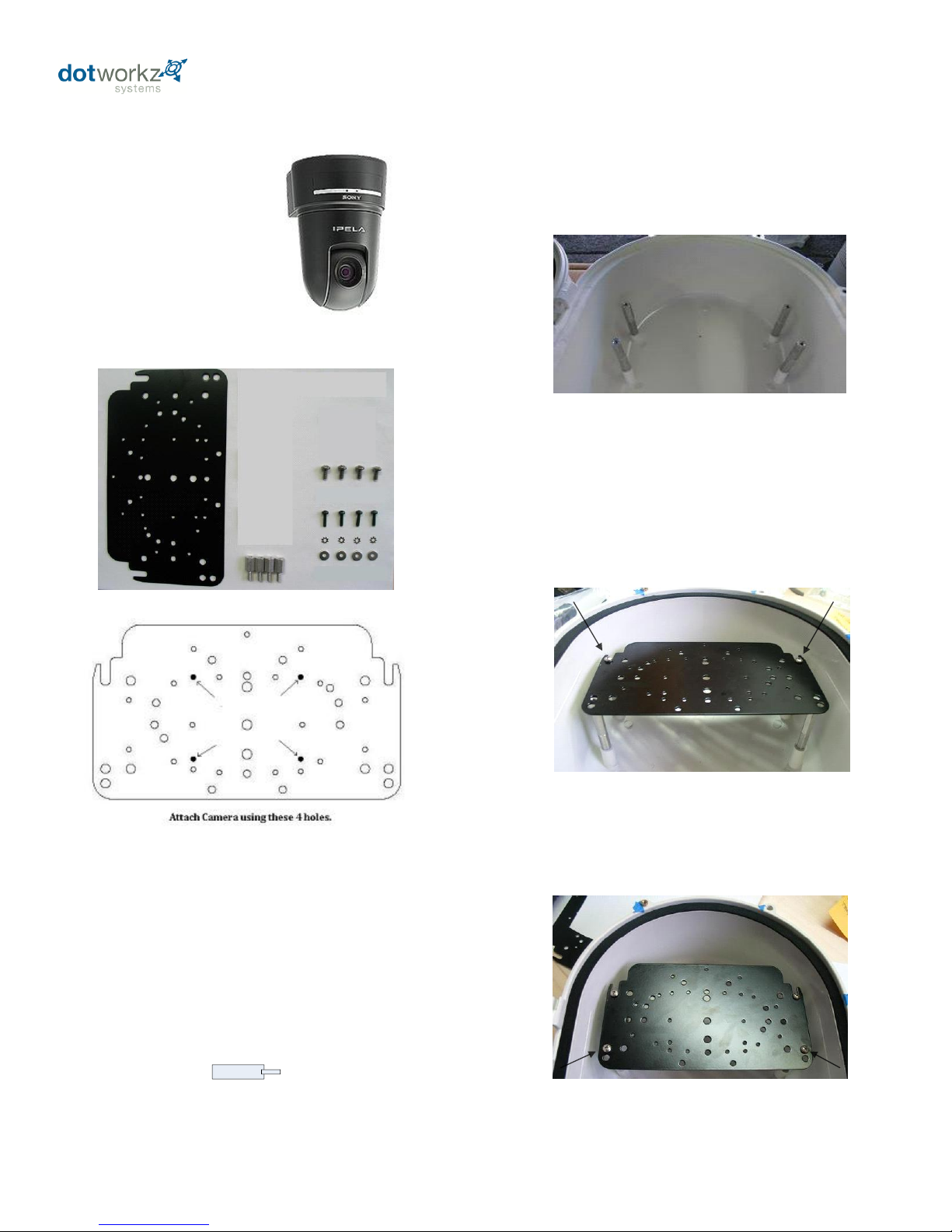
Installing Camera Bracket
Sony RX550N
1. Install the Sony RX550N camera onto the
D2 Camera Bracket with (4) m3-.5 ½” long
screws, (4) m3 external lock washer, and (4)
m3 1/8" washer that are included.
Required components (see component
checklist): Part # 1,2,12,14,15, & 16
4. Now slide the camera bracket with the
camera into place to line up with 4 screws
holes from the standoffs.
5. Use (4) #8-32 screws (Phillips head) to
secure the bracket into place.
Again, make sure the camera
bracket is facing the right direction.
This edge nests in arch at front of D2
This edge of the bracket faces back of the D2 enclosure
Tip: Insert (2) #8-32 screws in the front two
standoffs to provide a guide to slide the
camera bracket into. The last two corner
holes should line up and be secured last.
3. The .5" standoffs will be inserted on the
upper portion of the D2.
2. The Sony RX550N camera requires a .5"
spacing for optimal fit and operation. Use (4)
.5" standoffs that are included.
.5"
Picture represents standoff location & orientation.
Height of standoffs will vary depending on camera used.
Picture represents camera bracket orientation & how it is
secured. Don’t’ forget to mount your camera to the D2
camera bracket based on instructions.
24
Page 28
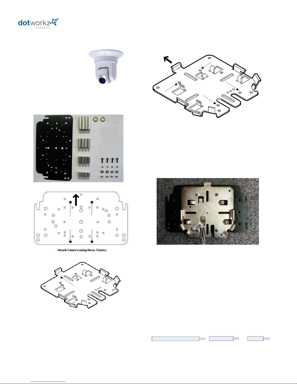
Installing Camera Bracket
Toshiba WB21A
2. Do this by aligning the four holes on the D2
camera bracket with the Toshiba ceiling bracket
adapter. Use (4) m3-.5 ½” long screws, (4) m3
external lock washer, (4) m3 1/8" washers, and
(4) m3 lock nuts that are included to secure the
toshiba ceiling adapter to the D2 camera bracket.
Required components (see component
checklist): Part # 1,2,3,4,5,6,14,15,16,& 17
.5"
.75"
This edge nests in arch at front of D2
This edge of the bracket faces back of the D2 enclosure
Align these 4 holes with the D2
bracket holes for the Toshiba WB21A
4. The Toshiba WB21A PTZ camera requires a
2.75" spacing for optimal fit and operation. Use
(1) 1.5" standoff, (1) .75" standoff, and (1) .5"
standoffs that are provided to create a 2.75"
standoff. You will need to create 4 of these with
the included hardware.
1. To install the Toshiba WB21A in the D2
Enclosure we must first install the Toshiba
WB21A ceiling bracket adapter that came with
the camera onto the D2 camera mounting plate.
Toshiba WB21A Ceiling bracket that came with the camera.
*This is a required item for installation*
3. Next follow the Toshiba WB21A installation
instruction to secure the camera to the ceiling
bracket adapter that is now attached to the D2
Camera Bracket.
1.5"
25
Page 29
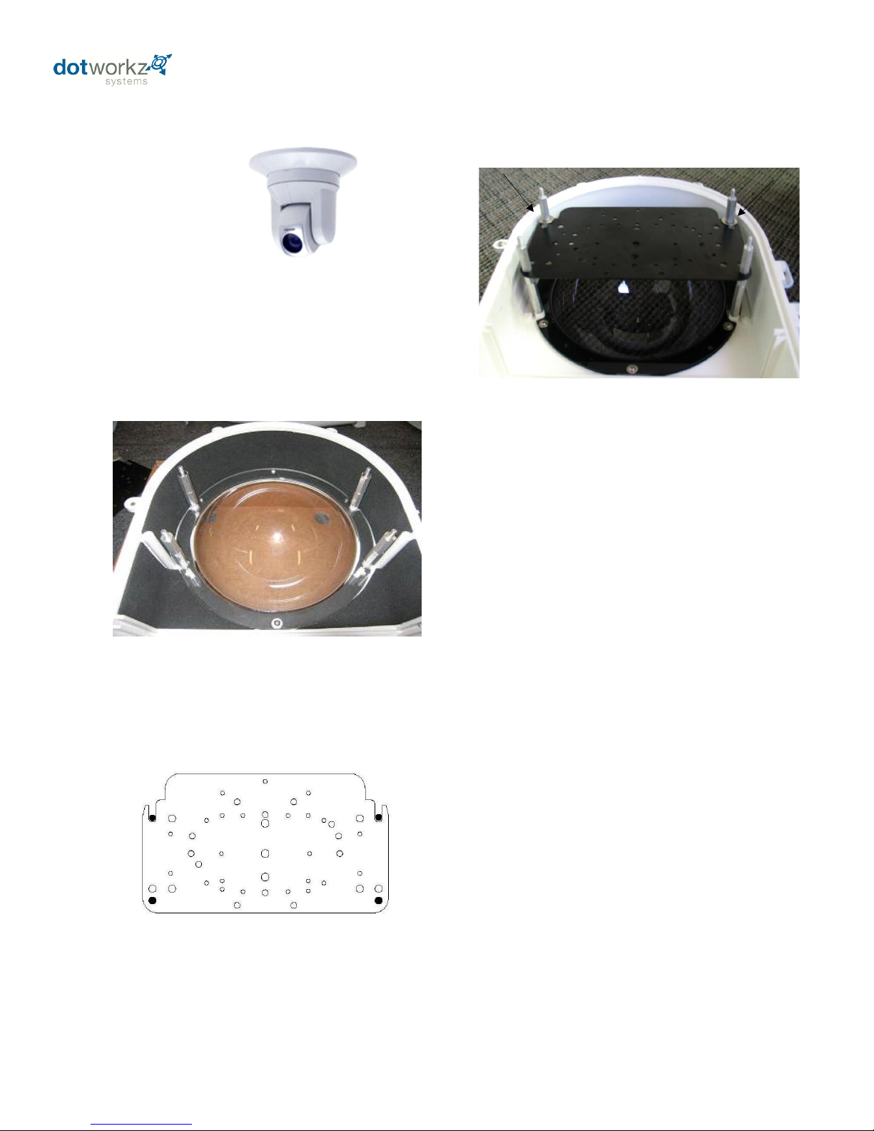
6. Now slide the camera bracket with the camera
into place to line up with 4 screws from the
standoffs.
Continued . . . . . . . .
Installing Camera Bracket
Toshiba WB21A
5. The 2.75" standoffs will be inserted on the
lower portion of the D2.
Picture represents standoff location & orientation.
Height of standoffs will vary depending on camera used.
7. Secure the plate by using (4) 1.0" standoffs to
lock the bracket in place. The two front location
will require the use of (2) .25" washer. See
picture.
Picture represents camera bracket orientation & how it is
secured. Don’t’ forget to mount your camera to the D2
camera bracket based on instructions.
26
Page 30
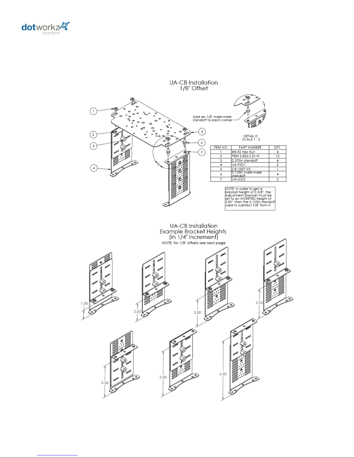
Optional Steady Step Mounting System
Steady Step Bracket Steps adjust in ¼” increments. To adjust 1/8” between step settings, add 1/8” brass male-male hex stand-off
(ITEM NO. 6) shown in detail D, by threading on top of movable slide bracket, then fastening camera bracket (CB-1007 or AB-1007).
27
Page 31
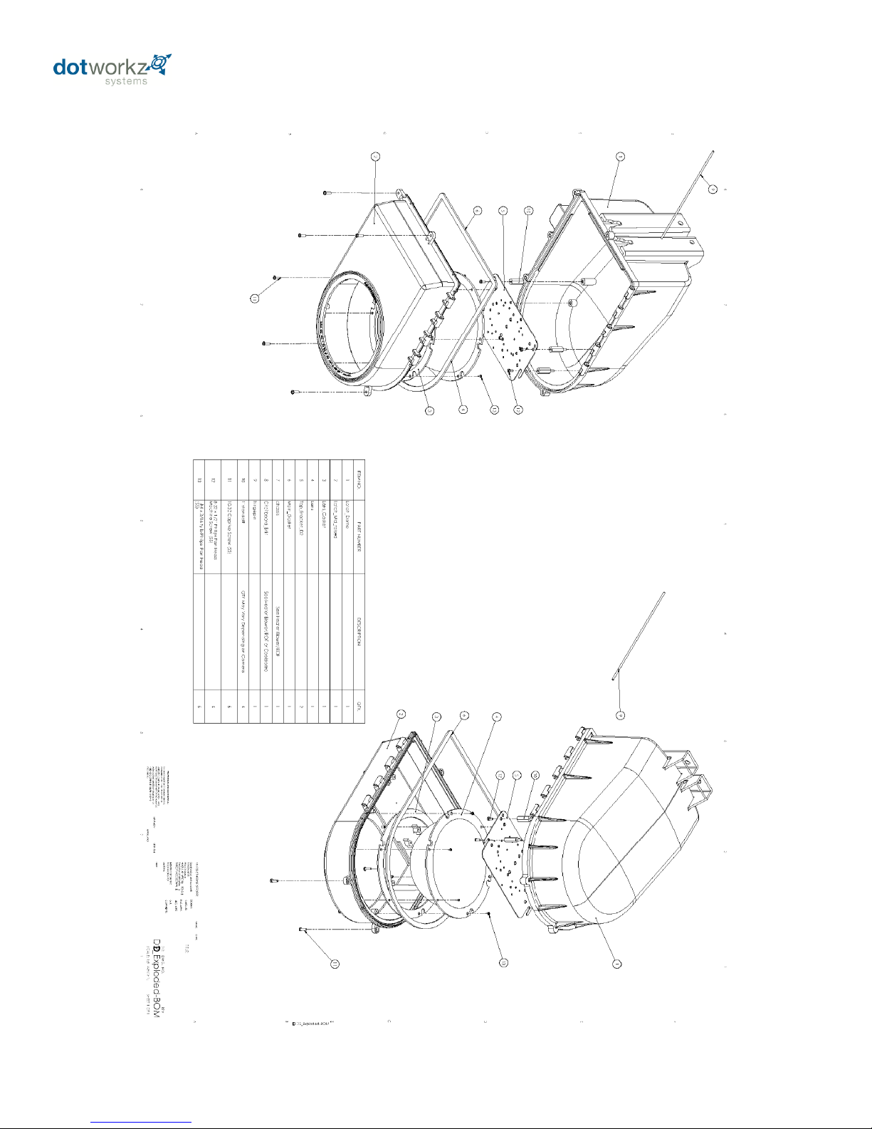
D2 Exploded Detail
28
Page 32
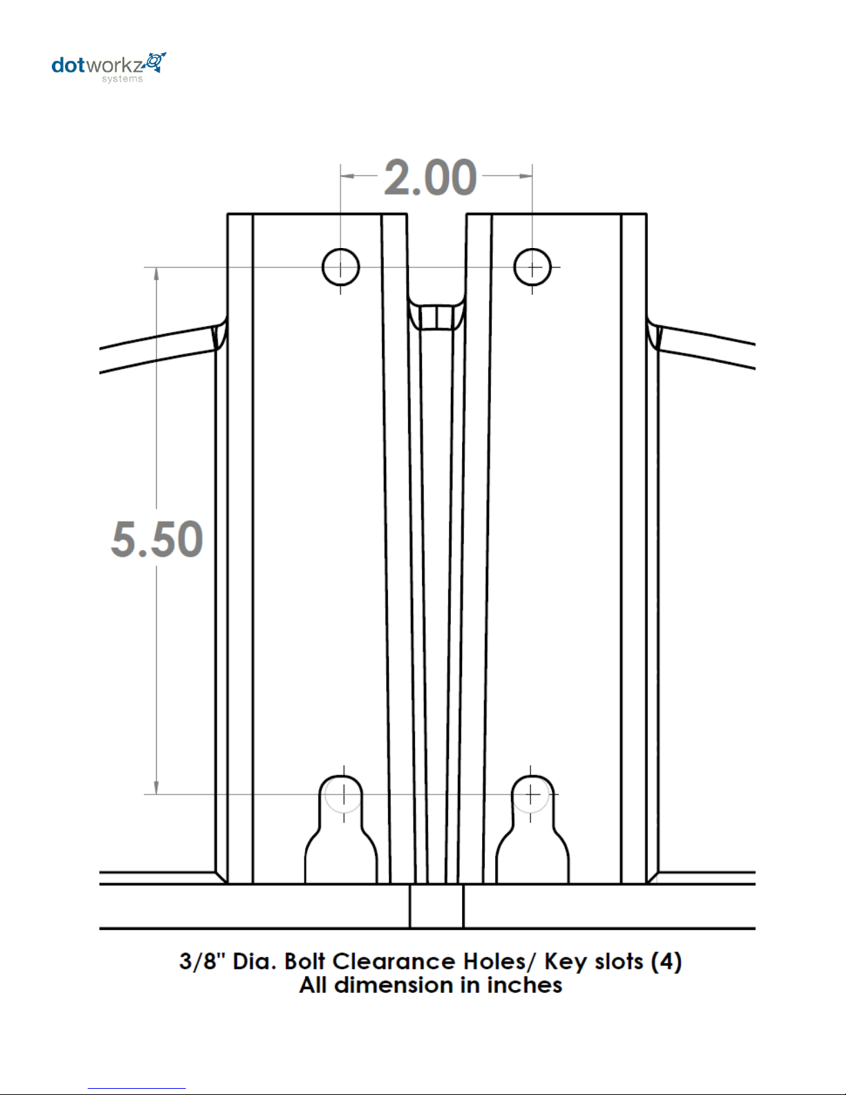
D2 Mounting Detail
29
 Loading...