

Page 1

DOT-X SERIES
Handheld Addressable
Remote Controls
Publication No. 01121 Rev B
160 FIRST STREET S.E.
ST. PAUL, MN 55112-7894
PHONE 651-633-1742
FAX: 651-633-1065
www.dotronix.com
User’s Manual
Page 2
Dotronix Limited W arranty
Dotronix warrants that for one (1) year from date original purchase, it
will, at its option, repair, replace or refund the purchase price of any product which it
manufactured that proves defective in material or workmanship in normal use and
service.
To obtain service under this Warranty, contact Dotronix Inc. at the address below, within
one (1) year of original purchase, to receive a Return Material Authorization (RMA)
number. Then ship the product believed to be defective, transportation prepaid, for
inspection.
Dotronix shall not be responsible for unauthorized returns that do not list the RMA number
and quantity returned on the outside of the shipping container (i.e. on packing list in
plain view).
For products supplied without a frame (Less CRT and Printed Circuit Board Mounting),
the buyer must inspect the products within ten (10) days of receipt. After ten (10) days
have lapsed, there shall be no warranty coverage for broken or damaged parts, or
misalignment (i.e. broken torque seals where used). The products will be packed to allow
Buyer to test the unit within its packing carrier.
This Warranty applies only to goods manufactured by Dotronix Inc. Various component
parts manufactured by others (such as cathode ray tubes, semi-conductors, and fuses
) are covered by the separate warranty of their manufacturers. Where Dotronix, Inc.
warranty differs, only the warranty of the original component part manufacturer is offered.
Of course, the Dotronix warranty does not apply to CRT's that are scratched, broken,
burned or have imperfections in any special coatings. It also does not apply to products
which have been altered, damaged, abused, or subjected to misuse, or repaired by
anyone other than an authorized Dotronix repair person.
These displays require DHHS traceability under sub-part E, Section 1002.40 of the
Regulations for the Administration and Enforcement of the Radiation Control for Health
and Safety Act of 1968. It is the customer's responsibility to maintain records that satisfy
this requirement.
THE TERMS OF THIS WARRANTY CONSTITUTES THE BUYER'S SOLE AND
EXCLUSIVE REMEDY AGAINST DOTRONIX. THERE IS NO IMPLIED WARRANTY
OF MERCHANTABILITY OR FITNESS FOR A PARTICULAR PURPOSE. UNDER NO
Products returned that are not identified in accordance with the above procedure
will be refused and returned at Buyer's expense.
To obtain a Return Material Authorization (RMA) number contact:
DOTRONIX INC.
160 First Street S.E. • St. Paul • Minnesota • 55112-7894
Phone 651-633-1742 • FAX 651-633-1065
All products returned to Dotronix must include:
1. A tag or label on each unit with a description of the defect or reason for return,
or identify each unit on the packing list by serial number and defect.
2. A packing list attached to the outside of the shipping container showing the
Return Authorization Number (RMA) and the quantity returned.
© Copyright 2001, Dotronix, Inc.
Publication No.01211B
160 First Street S.E.
St. Paul, MN 55112-7894, USA
This remote control contains circuits and components designed to meet
specific performance and safety requirements. No component changes
may be made without the written permission of the manufacturer.
To prevent electrical shock, do
not
attempt to disassemble the monitor.
There are no user-serviceable parts inside. Servicing, if required, should be
performed only by qualified service technicians familiar with the equipment
and safety procedures.
Servicing by unauthorized personnel may be
dangerous
and will void
the warranty.
If any damage to the remote control is found, report it immediately to Dotronix.
DO NOT RETURN DAMAGED MERCHANDISE TO THE MANUFACTURER
UNTIL AN APPROPRIATE CLAIM HAS BEEN FILED WITH THE CARRIER AND
A RETURN MATERIAL AUTHORIZATION NUMBER (RMA) HAS BEEN RECEIVED FROM THE MANUFACTURER.
All rights reserved. No part of this publication may be reproduced, stored in a retrieval system, or transmitted, in any form
or by any means, mechanical, photocopying, recording or
otherwise, without the prior written permission of Dotronix, Inc.
No patent liability is assumed with respect to the use of the
information contained herein. Where every precaution has
been taken in the preparation of this manual, Dotronix, Inc. and
the author assume no responsibility for errors or omissions.
Neither is any liability assumed for damage resulting from the
use of the information contained herein.
Specifications are subject to change due to technological
progress.
PRECAUTIONS
1
Page 3

Congratulations on your purchase of a new DOT-X Series with HARC
(Handheld Addressable Remote Control) option.
This manual has been prepared to act as a guide in the operation of your unit
when the HarcPlus option is installed. Please read the following operating
instructions carefully before using your unit so that you are familiar with all
of its features and capabilities. All precautions and safety warnings should
be read and strictly observed.
SERVICE PACK CONTENTS
The service pack consists of the following:
• Storage box
• Remote Control
• 2 AAA Batteries
• Adjustment Stick
• This Manual
GETTING STARTED
Refer to the monitor manual for connecting power and signal to the
monitor.
For initial operation of multiple unit installations, apply power to only one
unit at a time, while changing the unit identification number (Unit ID) from
the factory set 01 to a sequence of unique numbers for each unit. (See
Changing Security Code and Unit Number.)
Unpack the remote control and install batteries.
The DOT-X SERIES with HARC responds to remote control inputs in a
manner similar to many other remote control devices including TVs,
VCRS etc. with two important differences. First, a security code is
required before access to any menus is allowed. Second, a unit selection number is required to select one unit from a group of several units,
allowing individual adjustments to individual units with one remote
control.
Until the security code and unit selection numbers are entered, the
monitor will not respond to the remote control.
INTRODUCTION
INDEX
ACTIVATING OPTIONS 11
ADVANCED SETUP MENU 7
AUTOMATIC COLOR BALANCE 16
AVAILABLE MENUS 6
CHANGING SECURITY CODE AND UNIT NUMBER 8
COLOR MENU 6
CUSTOM OPTIONS 11
DE-ACTIVATING SECURITY 9
GEOMETRY MENU 6
GETTING STARTED 2
INTRODUCTION 2
IR MODULE 20 18
IR MODULE 29 17
JUMPER LOCATIONS 10
LOST OR FORGOTTEN SECURITY CODE 15
MENU - ADVANCED SETUP 7
MENU - AVAILABLE 6
MENU - COLOR 6
MENU - GEOMETRY 6
MENU - SELECTION 7
MENU - TO ACTIVATE 4
ON/OFF TIMER PROGRAMMING 13
PRECAUTIONS 1
PROGRAMMING ON/OFF TIMER 13
PROGRAMMING PURITY GUARD TIMER 12
PURITY GUARD TIMER PROGRAMMING 12
REMOTE CONTROL PICTORIAL 5
REMOTE CONTROL PICTORIAL 19
SECURITY DE-ACTIVATING 9
SECURITY CODE - CHANGING 8
SECURITY CODE - LOST 15
SELECTION MENU 7
SERVICE PACK CONTENTS 2
SETTING THE CLOCK 11
TO ACTIVATE MENUS AND CONTROLS 3
UTILITY INFORMATION SCREEN 15
WARRANTY 20
21 2
Page 4
Stand in front of the unit (monitor) and aim the remote at the InfraRed
(IR) receiver located on the upper left corner of the unit. Press and hold
the ENTER key on the remote for several seconds (typically 6 to 8
seconds).
The following on screen display (OSD) will appear.
MODEL M by DOTRONIX
TO ACTIVATE MENUS AND CONTROLS
KEY IN SECURITY CODE:
THEN PRESS ENTER KEY
The factory set security code is 5432. You can change this code at any
time. Refer to a later section of this manual titled CHANGING SECU-
RITY CODE AND UNIT NUMBER. At this point key in the security code
5432. As each number is pressed, an x will appear after the KEY IN
SECURITY CODE: line. If you miss-key a number the x’s will disappear
allowing you another chance to enter the code. When the correct code
is entered, press the ENTER key.
The following on screen display (OSD) will appear.
TO ACTIVATE THIS SET KEY IN 01
KEY IN SET #:
All units are shipped from the factory programmed as unit # 01. For
multiple unit installations, you will want to change the unit number of all
but one unit to other numbers. Typically the units are numbered in
sequence from 01 upward. The DOT-X SERIES HARC will accept unit
numbers up to 99. (If you need more than 99, consult the factory for a
special program.) At this point, key in 01, the numbers will appear after
the colon. If you miss-key the number, simply key in the desired number, the new number will replace the miss-keyed number. When you are
satisfied with the number, press the ENTER key.
TO ACTIVATE MENUS AND CONTROLS
3
20
NOTES
Page 5
TO ACTIVATE MENUS AND CONTROLS
The following on screen display (OSD) will appear.
THIS UNIT SELECTED
ALL MENUS/CONTROLS ACTIVE
press PREV. CH TO DE-SELECT UNIT
At this point, you can use the remote to control all available functions of
the unit. Please refer to later sections of this manual for details on using
those controls.
In a multi-unit installation, units that are not selected may not clear their
screen after the desired unit is selected. Security or unit-id screens can
be cleared on these units by pressing the MUTE (or M) key on the
remote and pointing the remote at the non-selected unit(s).
If this is a multiple unit (monitor) installation, this is a good time to
change the unit number so that each unit will have a unique number
when all units are powered up. Refer to the section of this manual titled
CHANGING SECURITY CODE AND UNIT NUMBER for the procedure
to change the unit number. If you desire, you can change the security
code at the same time.
When you are done using the controls, press the PREV. CH. key.
This de-selects the unit, returning security and unit selection to
their original state. To re-select this unit or to select another unit,
follow the same procedure starting with pressing and holding the
ENTER key.
If no remote control activity is sensed for 10 minutes, the HARC will deactivate security and it will be necessary to re-enter the security code
and reselect this unit following the procedure just described.
4
19
NOTES
Page 6
REMOTE CONTROL
The following has been prepared to act as a guide in the operation of your
HARC REMOTE CONTROL equipped units (monitors). Please read the
following operating instructions carefully so that you are familiar with all of
its features and capabilities before using your remote. All precautions and
safety warnings should be read and strictly observed.
Each unit can be controlled by entering a security code and unique unit
selection number as described in the previous section. After entering the
security code and unit selection numbers, the following controls and menus
are available.
5
18
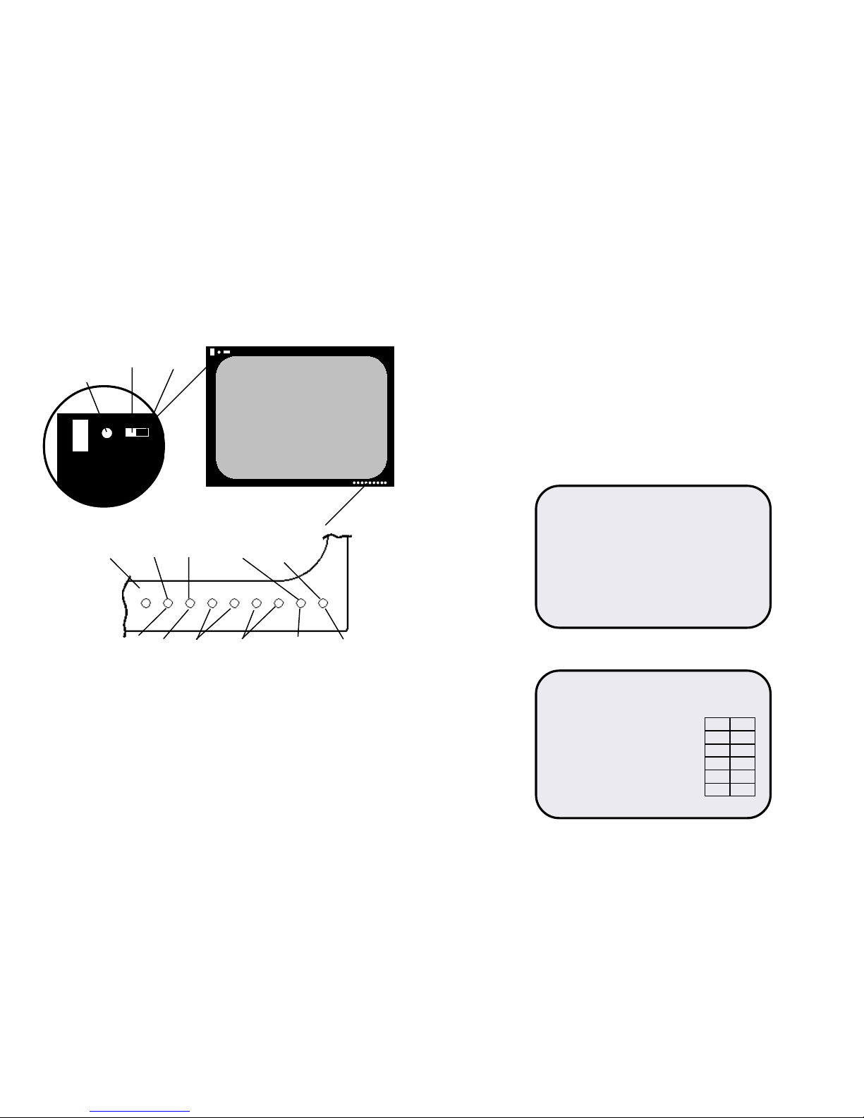
IR MODULE 20
IR MODULE INPUTS AND CONTROL LOCATIONS
See Detail
Off
On
IR Enable
Switch
DC Power Switch
(Not functional on this
model.)
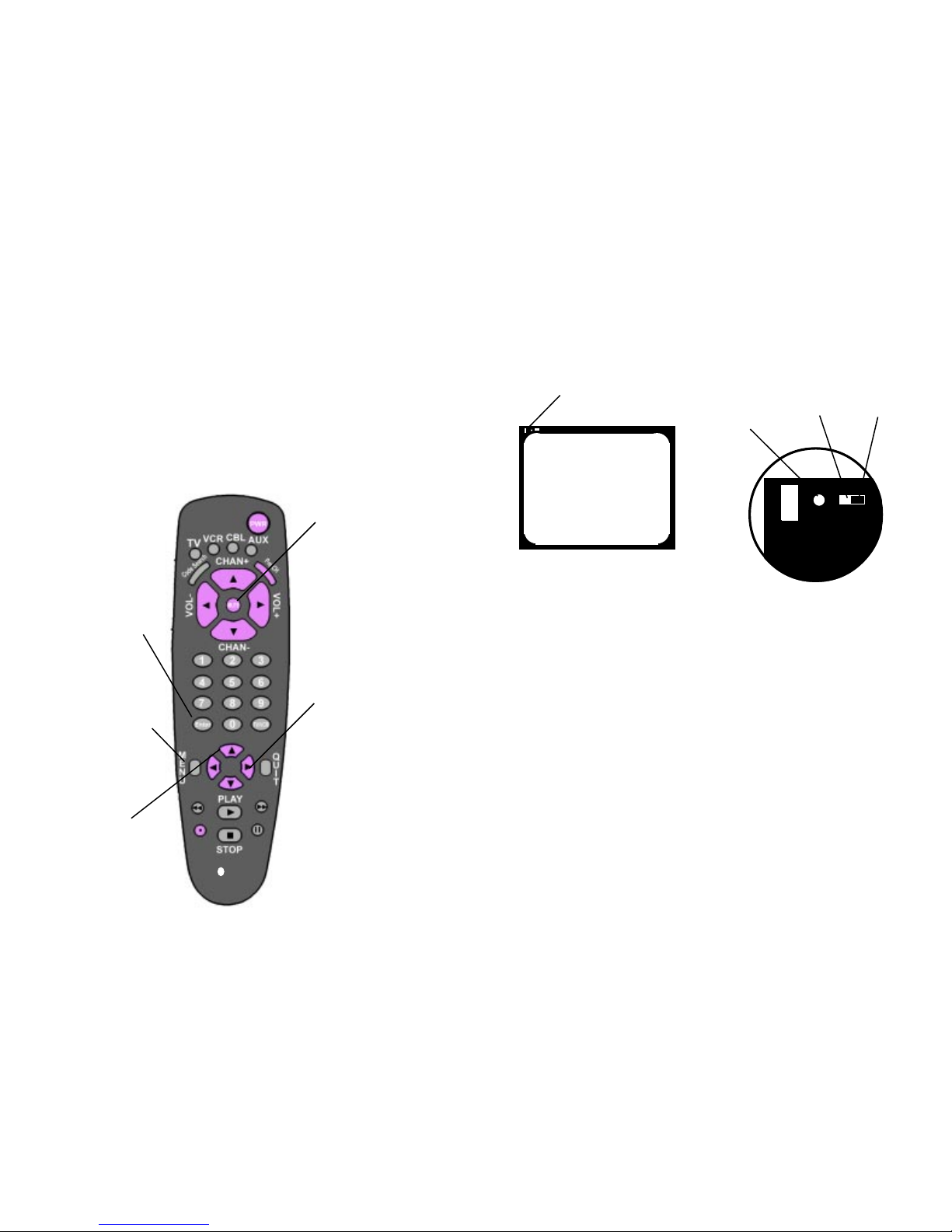
Press a left or
right arrow key to
adjust the
selected menu
option.
Press MENU
repeatedly to choose
between available
menus.
Press UP arrow key
repeatedly until the
desired option is
highlighted.
Press and hold ENTER
key for 6 - 8 seconds to
get security screen.
Press MUTE to clear
screens of non-selected
units.
DOT-X
Page 7
Off
On
Power
Switch
IR Enable
Switch
AVAILABLE MENUS
Your unit is menu operated. In other words, adjustments to the unit are
made via a list of choices which appear on your monitor screen. To view
these menus, press the MENU key on the remote. Press MENU repeatedly
to toggle through the 3 available menus. (Geometry, Color and Selection).
Press the UP or DOWN ARROW key to scroll down the list of available
adjustments. (Both UP and DOWN ARROW keys scroll down to allow
compatibility with universal remote controls.)
Press LEFT or RIGHT ARROW key to adjust selected item.
Press MENU for next menu
Press PREV. CH to EXIT
Geometry Menu
HORIZ POSITION 188
VERTICAL POSITION 102
HORIZONTAL SIZE 207
VERTICAL SIZE 156
PINCUSHION 111 *
PARALLELOGRAM 135 *
TILT 56 *
DEGAUSS
CONTRAST 99 BEAM
BRIGHTNESS 108 142
RED DRIVE 205
GREEN DRIVE 205
BLUE DRIVE 207
RED BKGRND 104
GREEN BKGRND 108
BLUE BKGRND 102
6
17
IR MODULE 29
Note: Manual power switch is inactive with HARC option installed.
Volume
V Size
V Position
Parallelgram
Degauss
Tilt
H Size
Brightness
Contrast
H Position
Pincushion
Units may or may not, have silkscreened control locations.
IR MODULE INPUTS AND CONTROL LOCATIONS
Color Menu
* Not available on 20
Off
On
Power
Switch
IR Enable
Switch
Page 8
AVAILABLE MENUS
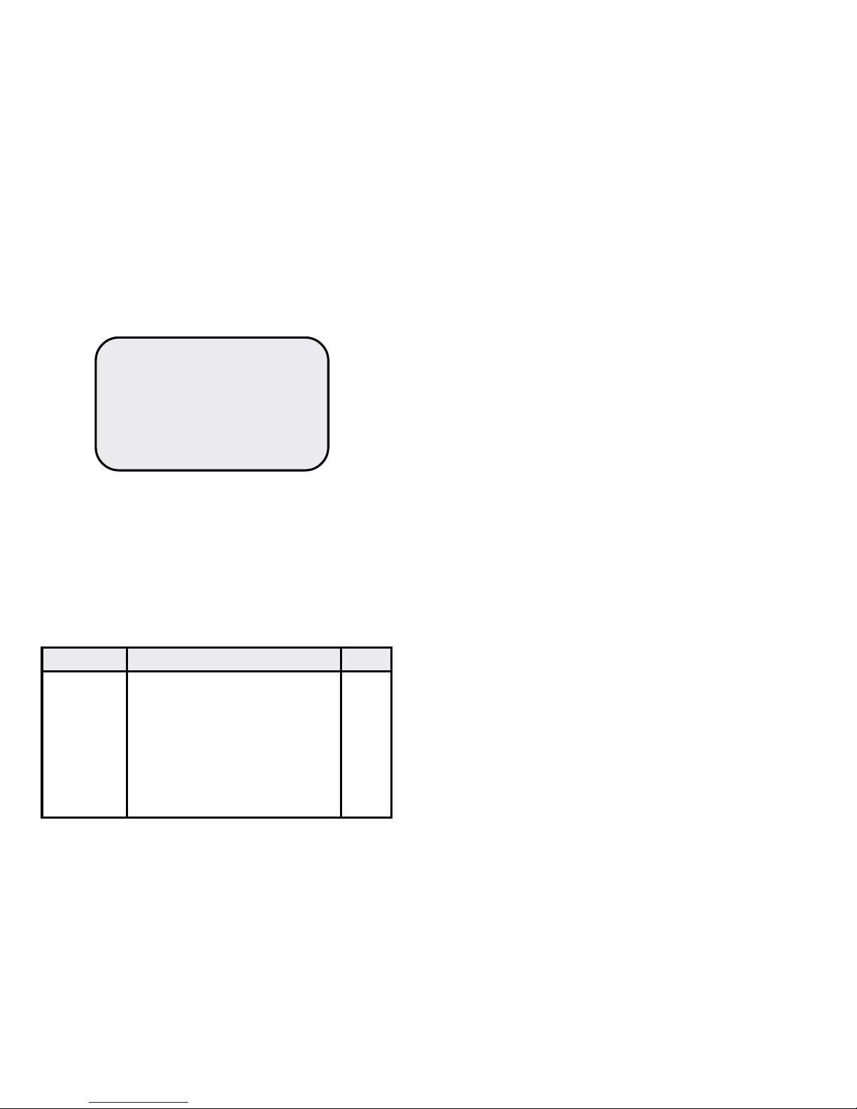
Selection Menu
0 (zero) Change security code and unit ID number. 8
7 Set or change clock. 11
9 Set or change purity guard time. 12
8 Display utility information screen. 15
TIMER or 6 Set or change ON/OFF (Start/Stop) timer 13
in 1 minute increments. **
1 Initiate automatic color balance 16
** Not available on the 20.
ADVANCED SETUP FEATURES
Advanced setup features are accessed by pressing and holding keys on
the remote control until the setup screen appears (typically 6 to 8
seconds).
Push & Hold Function Page
PURITY GUARD DISABLED
ORBITER ENABLED
UNIT ID ENABLED
ON OFF TIMER ** DISABLED
POWER GUARD ** ENABLED
AUTO COLOR BALDISABLED
7
16
CUSTOM OPTIONS
AUTOMATIC COLOR BALANCE
Automatic Color Balance is often referred to as Automatic Kinescope
Biasing (AKB). It restores the color balance of the monitor to factory set
values, compensating for aging of components within the monitor,
primarily aging of the phosphors within the cathode ray tube (CRT)
screen.
AKB can be initiated manually by pressing and holding the 1 (one)
key for 6 to 8 seconds. AKB blanks the screen then displays a red
square in the middle of the screen and adjusts the intensity of the
red square until it matches factory set parameters. This process is
repeated for the red square and then repeated twice each for a
green and blue square.
The AKB process can take from one to four minutes.
AKB will change the color drive and background values on the
Color Menu. It will not change the Contrast and Brightness values.
(Note that the color drive and background values can not be
changed manually on the Color Menu when Automatic Color
Balance is enabled. This is indicated by the blue color of the text.)
After completion of the manually initiated AKB process the on screen
display is erased, leaving a blank, black square, until another selection is
made via the remote control or the PREV. CH key is pressed to exit
security.
AKB can be initiated automatically at the same time as Purity Guard.
This will occur if the Automatic Color Balance selection is enabled on the
Selection Menu.
When AKB is initiated automatically, its operation is exactly as
described for the manually initiated function described above,
except that the screen is restored too normal after the completion
of the AKB. It is not necessary to select another menu or to push
the PRE CH key as in the manually initiated case.
** Not available on the 20.
Page 9
SECURITY CODE
CHANGING SECURITY CODE AND UNIT NUMBER
The security code and the unit number can be changed with the remote
control. First it is necessary to enter the current security code and unit
number, refer to GETTING STARTED earlier in this manual for the
procedures to enter the security code and unit number.
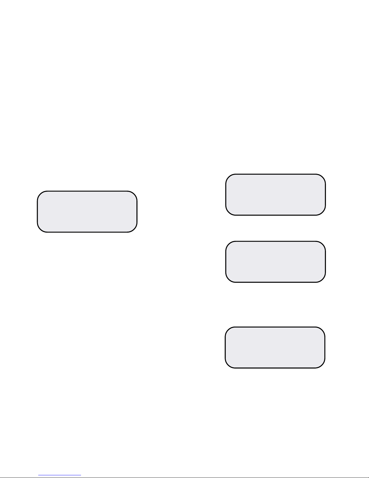
Press and hold the 0 (zero) key until the following screen appears
(typically 6-8 seconds).
KEY NEW 4 DIGIT SECURITY CODE
THEN PRESS ENTER KEY
Key in the new code. As you key in numbers, x’s will appear on the screen.
When you have keyed in 4 digits, the screen will change as follows.
KEY NEW 4 DIGIT SECURITY CODE
xxxx
THEN PRESS ENTER KEY
KEY NEW CODE AGAIN TO CONFIRM #
THEN PRESS ENTER KEY
At this point, you must key in the new number again or key in the current
code if you wish to retain the current code. Then press the ENTER key.
This saves the new code and makes it active for all future operations
requiring the security code.
Retain the new security code in a safe place for future reference.
The following on screen display (OSD) will appear.
KEY NEW 2 DIGIT UNIT ID NUMBER
01
THEN PRESS ENTER
8
CUSTOM OPTIONS
UTILITY INFORMATION SCREEN
Several useful values are displayed on the utility information screen. This
function displays that screen.
First it is necessary to enter the current security code and unit number,
refer to GETTING STARTED earlier in this manual for the procedures to
enter the security code and unit number.
Press and hold the 8 (eight) key until the following display appears.
07:28
M29+ r1.XX, COPYRIGHT © 1999
INTERNAL TEMP 24 Deg C
BEAM CURRENT 134
TOTAL TIME 000086 Hours
Press MENU key to return to menus or PREV. CH key to exit security.
LOST OR FORGOTTEN SECURITY CODE
A lost or forgotten security code can be handled by temporarily installing
the jumper that de-activates security, refer to the DE-ACTIVATING
SECURITY section for details. After installing the jumper use the remote
control to change the security code as described in the CHANGING
SECURITY CODE AND UNIT NUMBER. When the new code is saved,
remove the temporary jumper and security will be re-activated with the
new code.
15
Page 10

If you have changed the unit number from the factory setting, the current
number will appear where the 01 is shown above. To change the
number, key in the new number. Then press the ENTER key. If you do
not wish to change the number, simply press the ENTER key. Pressing
the ENTER key saves the number and makes it active for all future
operations requiring the unit number. It is not necessary to save the unit
number in a safe place since the unit will display its unit number on
screen whenever a unit number is required.
After pressing the ENTER key the on screen display is erased until
another selection is made via the remote control.
DE-ACTIVATING SECURITY
A jumper selection is provided on the HARC module to activate or deactivate security. To access this jumper remove the rear of the monitor
and find the HARC module.
Jumper location, labeled J4 is located near the center of the module and
will have jumper installed on one pin of the jumper location in such a way
that there is no connection between the pins of the jumper location.
Moving the jumper from this non-active position to the position where it
covers and connects the two pins de-activates security.
SECURITY CODE
9
If the entered time is not the desired time, key in the desired number
again (and again if necessary) until the displayed time is correct. Then
press the ENTER key. Repeat for the new Stop time.
Pressing the ENTER key saves the displayed times and as the new
Start and Stop times.
After pressing the ENTER key the on screen display is erased until
another selection is made via the remote control.
Clock must be set correctly (see SETTING THE CLOCK) for ON/OFF
times to occur at entered settings.
CUSTOM OPTIONS
14
Page 11
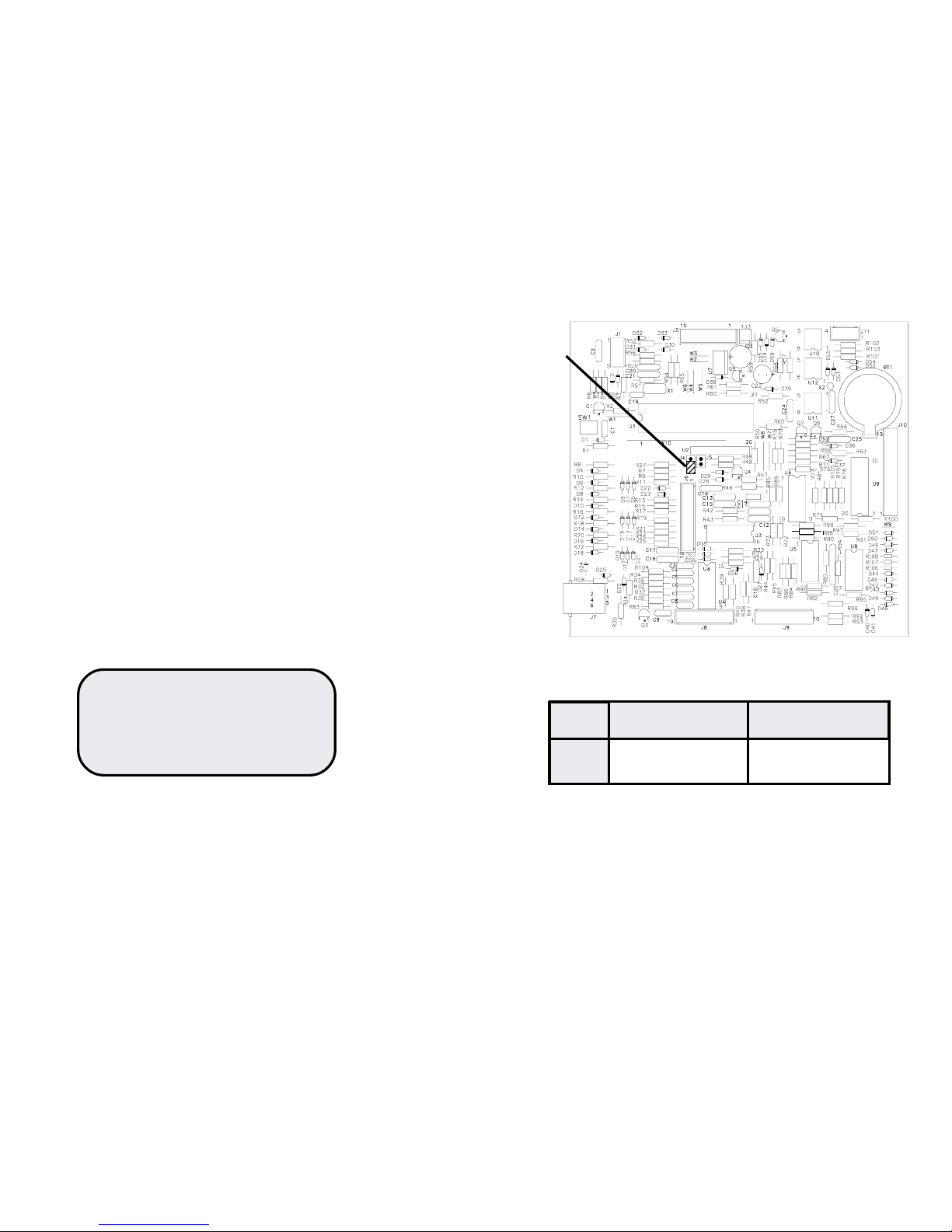
Jumper
Location
SECURITY CODE
DOT-X Series HARC module
Jumper Pins disconnected Pins connected
location (Factory setting)
J4 Security Active No Security
Jumper J4 will de-activate security when it is placed in the position to
connect the pins of J4. Some installations do not require security and
this option may be used in those cases. This option is also useful to
temporarily bypass security in case the security code is lost.
Jumper J5 is for factory use only and should never be installed.
10
13
KEY NEW START TIME
_8:30
THEN PRESS ENTER KEY
KEY NEW STOP TIME
16:15
THEN PRESS ENTER KEY
The times displayed are the current Start and Stop times and may be
any value from 0:00 to 23:59.
To change the times, key in the new Start time. Notice that as the
numbers are keyed in they move from left to right until all four digits have
been entered.
Some digits are not accepted. For example numbers larger than 2 that will be in the first
digit position are not accepted, numbers larger than 4 are not accepted for the second digit
and numbers larger than 5 are not accepted for the third digit.
CUSTOM OPTIONS
PROGRAMMING ON/OFF TIMER * (Not available on the 20)
In some installations it will be desirable for the monitor(s) to turn on an
off at the same time each day. The programmable ON/OFF timer
provides this function.
As shipped from the factory, the ON/OFF timer is not active. To activate
the ON/Off timer, select ON/OFF timer on the selection menu and press
the right arrow key until the word “ENABLED” appears. If the ON/OFF
timer is not activated, the timer can be programmed as described below,
but the ON/OFF action will not occur until the ON/OFF function is
activated.
The ON/OFF timer depends on the monitor clock. If the clock is not set
properly or is not operating, the ON/OFF timer will not work properly. To
set the monitor clock, refer to earlier section titled
SETTING THE CLOCK.
To set the ON/OFF time, first it is necessary to enter the security
code and unit number, refer to GETTING STARTED earlier in this
manual for the procedures to enter the security code and unit number.
Then press and hold the TIMER key or 6 key until the following
screen appears (typically 6 – 8 seconds).
Page 12
1211
CUSTOM OPTIONS
SETTING THE CLOCK
To set the clock, first it is necassary to enter the security code and unit
number, refer to GETTING STARTED earlier in this manual for the
procedures to enter the security code and unit number.
Then press and hold the 7 (seven) key until the following screen
appears (typically 6-8 seconds).
KEY NEW PURITY GUARD TIME
_4:25
THEN PRESS ENTER KEY.
The time displayed is the current time and may be any value from 00:00
to 23:59. Notice that the time is in 24 hour format.
To accept the current time, press the ENTER key.
To change the time, key in the new time.. Notice that as the numbers are
keyed in they move from left to right until all four digits have been
entered.
Some digits are not accepted. For example, numbers larger than 2 that
will be in the first digit position are not accepted, numbers larger than 4
are not excepted in for the second digit and numbers larger than 5 are
not accepted for the third digit.
If the entered time is not the desired time, key in the desired number
again (and again if necassary) until the displayed time is correct. Then
press the ENTER key.
Pressing ENTER key saves the numbers.
After pressing the ENTER key, the on screen display is erased until
another selection is made via the remote control.
CUSTOM OPTIONS
PROGRAMMING PURITY GUARD TIMER
Purity Guard activates the Degauss function and on units with HarcPlus,
the automatic color balance feature of the monitor, once each 24 hour
period. Degauss compensates for the effects of stray magnetic fields
including the earth’s field, from affecting the quality of the picture presented by the monitor. See Automatic Color Balance for a description.
Degauss is activated at power up which is sufficient for monitors that are
powered down at least once each day. For units that operate continuously, it is recommended that the degauss circuit be operated at a
selected time each day. Purity Guard provides the timer and selection of
time for the degauss function.
As shipped from the factory, Purity Guard is not active. To activate
Purity Guard, select Purity Guard on the selection menu and press the
right arrow key until the word “ENABLED” appears. If Purity Guard is
disabled, the timer can be programmed as described below, but the
degauss action will not occur until Purity Guard is activated.
To set the Purity Guard time, first it is necessary to enter the security
code and unit number, refer to GETTING STARTED earlier in this
manual for the procedures to enter the security code and unit number.
Then press and hold the 9 (nine) key until the following screen
appears (typically 6 – 8 seconds).
KEY NEW PURITY GUARD TIME
_4:25
THEN PRESS ENTER KEY.
The time displayed is the current Purity Guard time and may be any value
from 00:00 to 23:59. Notice that the time is in 24 hour format.
To accept the current time, press the ENTER key
 Loading...