

Page 1
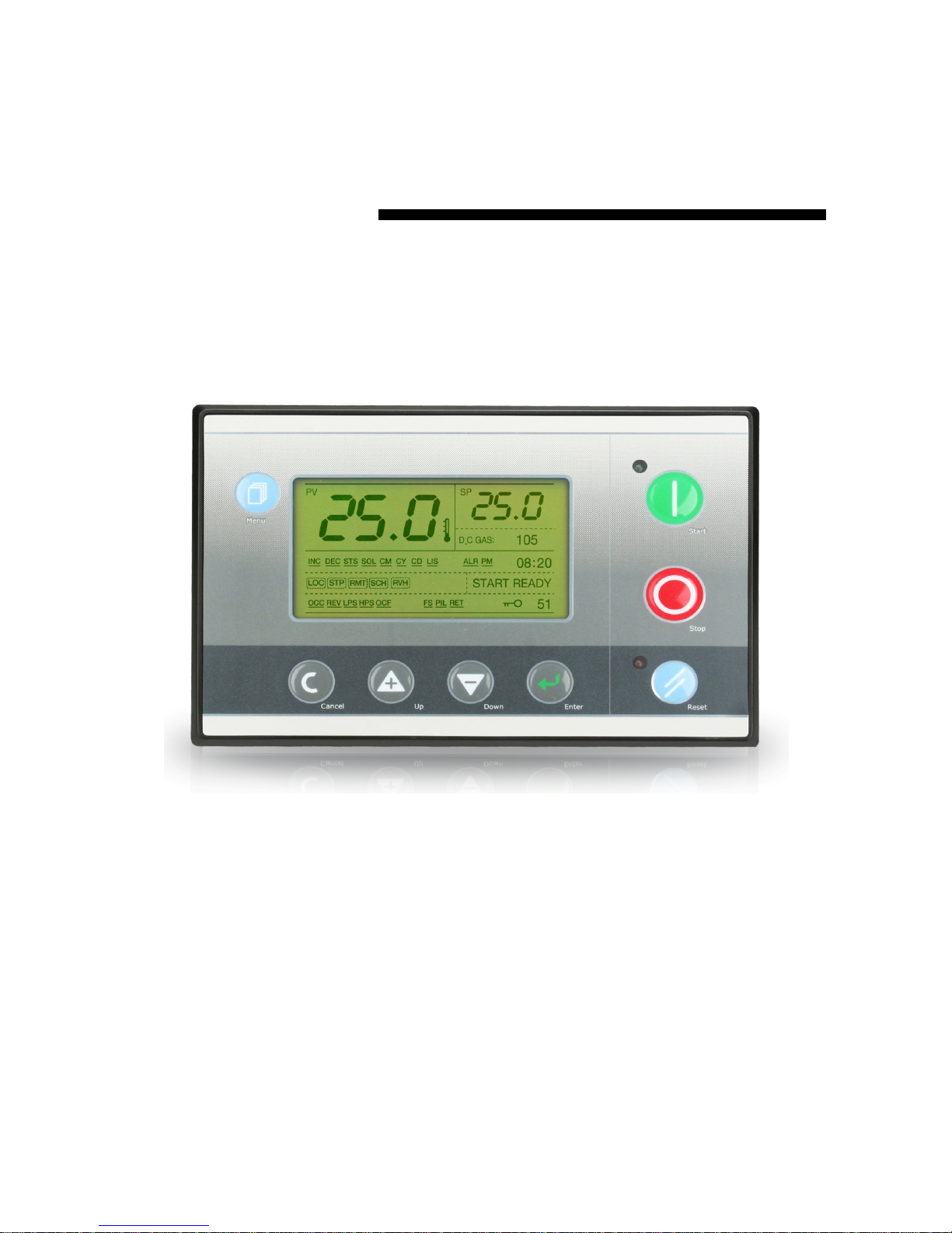
Application: Chiller, CDU, Spot Cooler
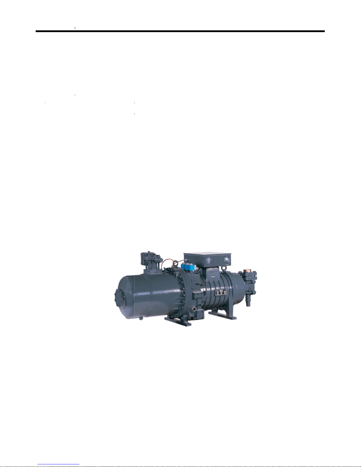
Compressor Maker: Bitzer, Roltec, Fusheng, Hanbell, Refcomp, Hitachi, Mitubishi, Etc
DOTECH, INC
Joongang-ilbo building 6F, Wonsi-dong, Danwon-gu
Ansan-si, Gyeonggi-do, KOREA
Tel
: 031-495-3767 , 031-495-3916 (Customer Service Center)
Fax
: 031-495-3917
Homepage
: www.dotech21.com
E-mail
Universal Intelligent Controlle
r
UIC-DX270 for Screw Compresso
r
2006-Apr rev. 1
Page 2

UIC-DX270 Series User’s Manual Rev 1.0
- 2 -
※ Certainly read 'warning matter for safety', and please use before using.
Warning matter for safety
This direction is for using the product correctly so that you could be safe from danger or incident.
Please carefully keep this all direction.
z Please use with being attached to a dual safety device in case of using for controlling instruments which could be
effective to human life or property (ex: controlling atomic energy, medical instruments, cars, trains, flights, burners,
amusement instruments or safety machinery).
z Please use with panel, there is a possibility getting an electric shock.
z Do not inspect or test with connecting power.
z Please connect after checking the terminal number when connecting power.
z Do not reorganize except mechanic from DOTECH.
z Do not use outdoor. It would be a cause making the product life shorter.
z When connecting wires, please give a good screw on terminal. There is a possibility causing a fire with bad connection.
z Please use in the proper performance zone. If you don’t, there is a possibility making the product life shorter or, causing a
fire accident.
z Do not use a load which is exceeded proper value of opening and shutting capacity of a relay contact. This will cause bad
insulation, bad contact and bad connection.
z When cleaning, water or liquid including oil are prohibited, only clean with soft and dried cloth.
z Do not use in the place where there is inflammability gas, explosiveness gas, moisture, a direct ray of light, radiation,
vibration and a shock.
z Please prevent from getting a dirt or leftover wire inside of this product.
z When connecting a sensor, please connect correctly after checking the polarity.
Some of the setting, size etc. on this manual could be changed without an advance notice.
Page 3

UIC-DX270 Series User’s Manual Rev 1.0
- 3 -
Warranty Information
This is the warranty below for customer who has a license or product from DOTEC.
The condition of warranty
The warranty period for DOTECH products is a year so that it is provided support of the product during the
warranty period.
『DOTECH does not have a responsibility for problems of product under the circumstance below.
In the case of using without concerning the proper form mentioned on the manual.
In the case of problems caused from both external artificial and environmental factors.
Please contact DOTECH in advance if there is any problem of product caused during the warranty period.
If the problem of product is informed from customer in the warranty period, it will be checked up in the customer area or
sent to DOTECH to check and conduct repair of exchange services directly. If the product is over the warranty period or
that is on the condition that it is not mentioned on manual, customer would be suggested to pay the cost of repair, exchange
and delivery.
On the condition that suggestions for ‘Warranty Condition Performance’ below are not against the law, DOTECH is not
responsible for any compensation and guarantee caused by losses or damages by business interruption, loss, return.
Warranty Condition Performance
DOTECH is not responsible for any loss, damages, expenses insisted by customer, delegate, contractor except for customer
claims caused by the condition of warranty above.
The condition of warranty mentioned above is the exclusive customer’s right. DOTECH refuses any conditions of
warranty for special purpose except for the condition of warranty.
Warranty Condition Performance does not apply any trouble caused by not following exact direction. It is responsibility for
customer to decide usage or product.
All the conditions of warranty are actually applied and Nobody has authority to modify or extend.
Page 4

UIC-DX270 Series User’s Manual Rev 1.0
- 4 -
I N D E X
1. OUTLINE .................................................................................................................................................................. 8
1)
SPECIAL MERITS ................................................................................................................................................................ 9
1-1) Countermeasure of the Noise
....................................................................................... 9
1-2) RISC TYPE MICOM
.................................................................................................... 9
1-3) Black box built-in: Operation recording system built-in
......................................................... 9
1-4) Display of operating state
........................................................................................... 9
1-5) Adoption Wide LCD Graphic (Wide Temperature Range Type : -20 ~ +70℃
) .............................. 9
1-6) Miniaturization, Slimmerlization
.................................................................................... 9
1-7) Expandability
........................................................................................................... 9
2)
BASIC FEATURES ............................................................................................................................................................. 10
2-1) General feature
....................................................................................................... 10
2-2) CPU and LCD
......................................................................................................... 10
2-3) Digital input/output
.................................................................................................. 10
2-4) Analog input/output
................................................................................................. 10
2-5) Communication feature
............................................................................................. 10
2-6) Installation features
.................................................................................................. 10
2. INPUT/OUTPUT FEATURE .................................................................................................................... 11
1)
DIGITAL INPUT SIGNAL ................................................................................................................................................. 11
2)
DIGITAL OUTPUT SIGNAL ............................................................................................................................................. 12
3)
ANALOG INPUT SIGNAL ................................................................................................................................................ 13
4)
ANALOG OUTPUT SIGNAL (OPTIONAL FUNCTION) .............................................................................................. 14
5)
COMMUNICATION SIGNAL (OPTIONAL FUNCTION) ............................................................................................ 15
5-1) SYSTEM BUS
.......................................................................................................... 15
5-2) LOCAL BUS
............................................................................................................ 15
6)
CONTROL POWER INPUT .............................................................................................................................................. 16
3. COMPOSITION ................................................................................................................................................ 17
1)
OPERATION AND DISPLAY ........................................................................................................................................... 17
1-1) General composition
................................................................................................ 17
1-2) Operation
............................................................................................................. 17
1-3) Setting up program
................................................................................................. 17
2)
OUTLINE DRAWING AND PROCESSING .................................................................................................................... 18
3)
DISPLAY OF OPERATING STATE ................................................................................................................................... 19
4)
FUNCTION OF AN OPERATION BUTTON .................................................................................................................. 19
5)
STATE DISPLAY LAMP .................................................................................................................................................... 19
Page 5

UIC-DX270 Series User’s Manual Rev 1.0
- 5 -
6) SYMBOL EXPLANATION ................................................................................................................................................ 21
6-1) Equipment state display
............................................................................................ 21
6-2) Digital input signal symbol
........................................................................................ 22
6-3) Digital output signal symbol
...................................................................................... 22
4. MENU COMPOSITION ............................................................................................................................... 23
1)
OPERATION AND DISPLAY ........................................................................................................................................... 23
2)
MENU STRUCTURE ......................................................................................................................................................... 24
3)
MENU ACCESS LEVEL ..................................................................................................................................................... 25
4)
RUN INFORMATION ....................................................................................................................................................... 26
5)
OPERATION ....................................................................................................................................................................... 26
6)
SCHEDULE OPERATION ................................................................................................................................................. 27
7)
TRIP LOG ........................................................................................................................................................................... 28
8)
TRIP AND ALARM ........................................................................................................................................................... 29
8-1) Trip alarm message
............................................................................................... 30
9)
EXTENT OPERATING SET ............................................................................................................................................... 32
10)
CONFIGURE .................................................................................................................................................................... 33
11)
CALIBRATION ................................................................................................................................................................. 34
12)
TEST MODE .................................................................................................................................................................... 35
13)
FACTORY SET ................................................................................................................................................................. 36
14)
SYSTEM DATE/TIME ..................................................................................................................................................... 37
5. INSTALLATION PROCESS .................................................................................................................... 38
1)
INSTALLATION PLACE .................................................................................................................................................... 38
2)
INSTALLATION PROCESS ............................................................................................................................................... 38
3)
BE WARNING MATTERS ACID CONNECTION WITH LINES ................................................................................... 38
6. ELECTRIC DRAWING ................................................................................................................................ 39
7. SENSOR DATA ............................................................................................................................................... 40
1)
TEMPERATURE SENSOR DATA ..................................................................................................................................... 40
Page 6
UIC-DX270 Series User’s Manual Rev 1.0
- 6 -
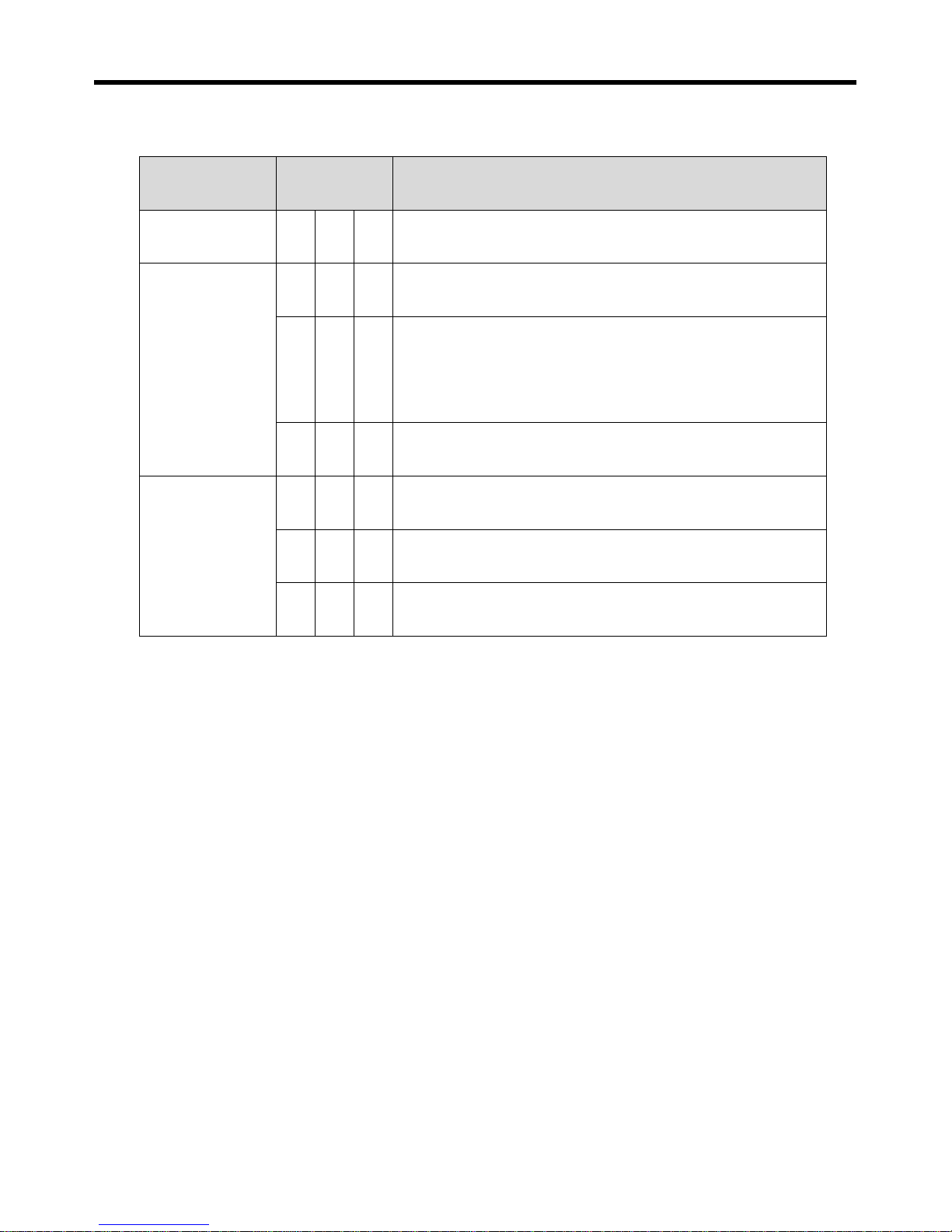
※ Please check the product to the model ordering before usage.
Model Suffix Code Description
DX270 - - - UIC for Screw Compressor (Chiller, CDU)
Type
- 0 0 None
- 1 0
Analog Output 3 Channel
(Temperature Retransmission)
- 0 1 With Communication RS-485 Mod-Bus
Language
- - - Korean
- E - English
- C - Chinese
z
Elements
DX270body ---- 1
DX270 only connector (4mm nut 4 included)
DX270-00 : (3P-1, 4P-1, 5P-4, 6P-2) ---- 1set
DX270-01 : (3P-2, 4P-1, 5P-4, 6P-2) ---- 1set
DX270-10 : (3P-1, 4P-1, 5P-4, 6P-3) ---- 1set
DX270-11 : (3P-2, 4P-1, 5P-4, 6P-3) ---- 1set
DX270 exclusive trans (P/N:24069001) ---- 1 (separately purchase)
Temperature sensor (DPR-TH2-06D100L) : Discharge gas temperature (separately purchase)
Temperature sensor for DX270 (DPR-TH1-06D100L) : Exit temperature (separately purchase)
Freezing exclusive use pressure sensor (-1 ~ 9 bar) (separately purchase)
Freezing exclusive use pressure sensor (0 ~ 30 bar) (separately purchase)
Page 7

UIC-DX270 Series User’s Manual Rev 1.0
- 7 -
※ Product Reference
DX200 : 1 C/S Screw Chiller / Controlling CPU
DX220 : 1~2 C/S Screw Chiller / Controlling CPU
DX240 : 1~4 C/S Screw Chiller / Controlling CPU
DX260 : Multi Compressor Controller / Be control possibility with a unit number.
DX270 : 1 C/S Screw Chiller / CDU control (Controlling steps)
DX230 : 1~2 C/S Round-trip/ Screw Chiller / Controlling CPU
DX230H : 1~2 C/S Round-trip / Controlling scroll hit pump
DX100 : Controlling Air handling unit
DX140 : Controlling stable temperature and humidity
Page 8
UI
C
1
Ueffsysinf
an
co
ef
f
-DX270 Se
r
. OUT
L
IC-DX270
icient drivin
tems atte
m
orming nec
d UIC-DX2
7
ndition and
iciently ope
▣ Reliabili
t
▣ Adopted
▣ Easy an
a
▣ A weekl
y
▣ Var iety
a
▣ Var ious
▣ One tou
(
r
ies
INE
is based o
n
g of a scre
w
pt an ener
g
essary mai
n
0 carries a
a machine
rate further
y adopted
h
wide graph
i
lyze the caus
timer is buil
nalog outp
u
product cov
e
ch setting: C
Bitzer, Roltec
,
microproc
e
compress
o
y-saving, o
r
tenance in
f
utomaticall
y
set up. Besi
a compress
o
igh RISC MI
C
c LCD displa
y
e of troubles
t, and autom
a
t (transfer e
x
rage (chiller,
apacity contr
o
Fusheng, H
a
(S-Se
r e
ssor, and
b
r. U IC-DX 2
7
affect an
a
ormation a
s
out the b
des, UIC-D
X
r.
OM.
ing Korean/
E
because of s
t
tion can call
it temperatu
r
CDU, startin
g
l method se
nbell, Refco
m
ies screw c
o
- 8 -
e control
d
0 is mana
g
larm, and
p
judgment
est operati
o
270 posses
s
nglish/Chine
s
oring 160 hi
a saving op
e
e, discharge
g
controller).
tting is possi
b
p, Hitachi,
M
mpressor
m
evices ele
c
ing intensi
v
revent prev
i
controls ca
n (control)
es the foll
o
e.
stories of Tri
p
rating.
as temperat
u
le.
itubishi, etc.)
ade by Ref
c
tronic the
ely a drivin
g
ously the o
pacity coor
d
according
wing tip fu
n
Warning (n
o
re)
omp LTD.)
User’s
M
high-tech c
of a com
p
ccurrence i
n
ination ti
m
to operatio
ction with
nvolatile).
anual Rev
arrying out
ressor, and
question,
a
ing. Correc
t
n situation
s
bases, and
c
1.0
an
be
nd
it,
of
c
an
Page 9

UIC-DX270 Series User’s Manual Rev 1.0
- 9 -
1) SPECIAL MERITS
UIC-DX270 supports a Korean display and trip alarm personal history for integrated controls and management of a
screw freezer, and be electronic control unit this only an excellent screw freezer having been equipped with stability.
Were adopting a digital algorithm process method by microprocessor of highly efficient RISC type, and a unification
did modular a display control module, and ensured a mounting space and stability. Delivery calls immediately a driving
situation to users to a display, and can provide convenience such as operation and maintenance etc.
1-1) Countermeasure of the Noise
A piece regarding noise measures will be the urea which is essential as controllers for industry. The digital
input/output signal the noise measures that isolation, an external signal does not flow into into boards are all
prepared. And the acid hardware watch dog timer which is restored automatically like CPU by noises dislikes 32msec,
and be operating to CPU of a board, A brown-out function becomes an innards, and be monitoring the control power
in the CPU inside by real time.
1-2) RISC TYPE MICOM
The assembly instruction code of CPU conducts 7.3738M instruction per second, controlling logic writing on CPU
spends about 1[msec] per cycle. Thus, it is less possibility to make trouble and much detailed to control than normal
controller.
1-3) Black box built-in: Operation recording system built-in
DX - 270 can save up to 160 events of trip warning background so that it is great to analyze trouble maintain the
product. Additionally, users can know the state of operation on the spot easily during trip.
1-4) Display of operating state
Have driving state of an air compressor and a function marking delay time and atmosphere time, and DX 270 series
can try to know at first sight driving state of a compressor.
1-5) Adoption Wide LCD Graphic (Wide Temperature Range Type : -20 ~ +70℃
)
The display of UIC-DX270 an equipment user adopted large graphical LCD so that operation and recognition were
easily possible. (
English, Korean, Chinese
) Display of UIC-DX-270
1-6) Miniaturization, Slimmerlization
Main control wealth and display addition unification is favorable to a space security.
1-7) Expandability
RS485 port assistance, Modbus RTU standard protocol assistance, MMI Software and automatic interface assistance.
Page 10
UIC-DX270 Series User’s Manual Rev 1.0
- 10 -
2) BASIC FEATURES
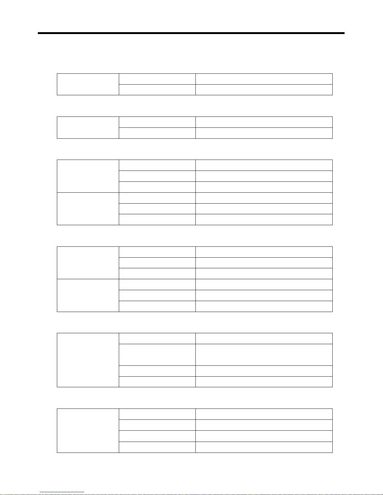
2-1) General feature
Power Conditions
Input power AC24V 50/60Hz, DC24V
Output power 20VA(Maximum)
2-2) CPU and LCD
CPU, LCD
C P U ATmega 128, 16MHz
L C D 240 X 128 pixel, LED Backlight
2-3) Digital input/output
Digital Input
Input Method Opto-Isolation
Number of Input 10 (5 X 2 Common)
Signal Power AC24V or DC24V
Digital Output
Output Method Relay contact
Number of Output 12, (4 X 3 Common)
Relay Contact 250V, 10A (NAIS JQ1P Series)
2-4) Analog input/output
Analog Input
Temperature Sensor NTC 3
0~1VDC, 4~20Madc 2 (sensor power 24V )
Declination Revision Software
Analog Output
Number of Channel 3 channel
Output Method 4~20mA
Setting Form software
2-5) Communication feature
Communication
Communication Method RS485(half-duplex), 2 Channel
Communication Speed
4800, 9600, 19200, 38400 BPS
Parity None, Data 8bit, Stop 1bit
Communication Distance 1.2Km (maximum)
Suggested Cable BELDEN 9841(2) or 8761
2-6) Installation features
Field Conditions
Install Place Indoor
Operation Temperature -10 ~ 60 ℃
Storage Temperature -30 ~ 80 ℃
Operation Humidity Non-humidity 5~95%
Page 11
UIC-DX270 Series User’s Manual Rev 1.0
- 11 -
2. INPUT/OUTPUT FEATURE
1) DIGITAL INPUT SIGNAL
Pin Name Function Active state
J13.1 ID1 Over-load Main Motor fault (open)
J13.2 ID2 Reverse-Phase Main Motor fault (open)
J13.3 ID3 Low-Pressure Switch Signal fault (open)
J13.4 ID4 High-Pressure Switch Signal fault (open)
J13.5 ID5 Oil Level Switch Signal fault (open)
J13.6 IDCM1 Input common terminal 1
Pin Name Function Active state
J14.1 ID6 INT • Oil Flow Signal fault (open)
J14.2 ID7 Condenser Fan Fault Signal fault (open)
J14.3 ID8 Flow Signal-Pump(Fan) Interlock fault (open)
J14.4 ID9 Over-load Pump(Fan) Motor fault (open)
J14.5 ID10 Remote Start/Stop Control Run (closed)
J14.6 IDCM2 Input common terminal 2
Page 12
UIC-DX270 Series User’s Manual Rev 1.0
- 12 -
2) DIGITAL OUTPUT SIGNAL
Pin Name Function Active state
J21.1 N1 Load Control Capacity SOL V/V (CR1) ON
J21.2 N2 Load Control Capacity SOL V/V (CR2) ON
J21.3 N3 Load Control Capacity SOL V/V (CR3) ON
J21.4 N4 Liquid SOL V/V ON
J21.5 C1 Output common terminal 1
Pin Name Function Active state
J22.1 N5 MC for Main / PW1 ON
J22.2 N6 MC for Start / PW2 ON
J22.3 N7 MC for Delta ON
J22.4 N8 Liquid Injection Sol V/V Control ON
J22.5 C2 Output common terminal 2
Pin Name Function Active state
J23.1 N9 Load Control Capacity SOL V/V (CR4)
J23.2 N10 Run State Signal Run (ON)
J23.3 N11 Total Alarm Signal Alarm (ON)
J23.4 N12 Pump(Fan) On/Off Signal ON
J23.5 C3 Output common terminal 3
Page 13
UIC-DX270 Series User’s Manual Rev 1.0
- 13 -
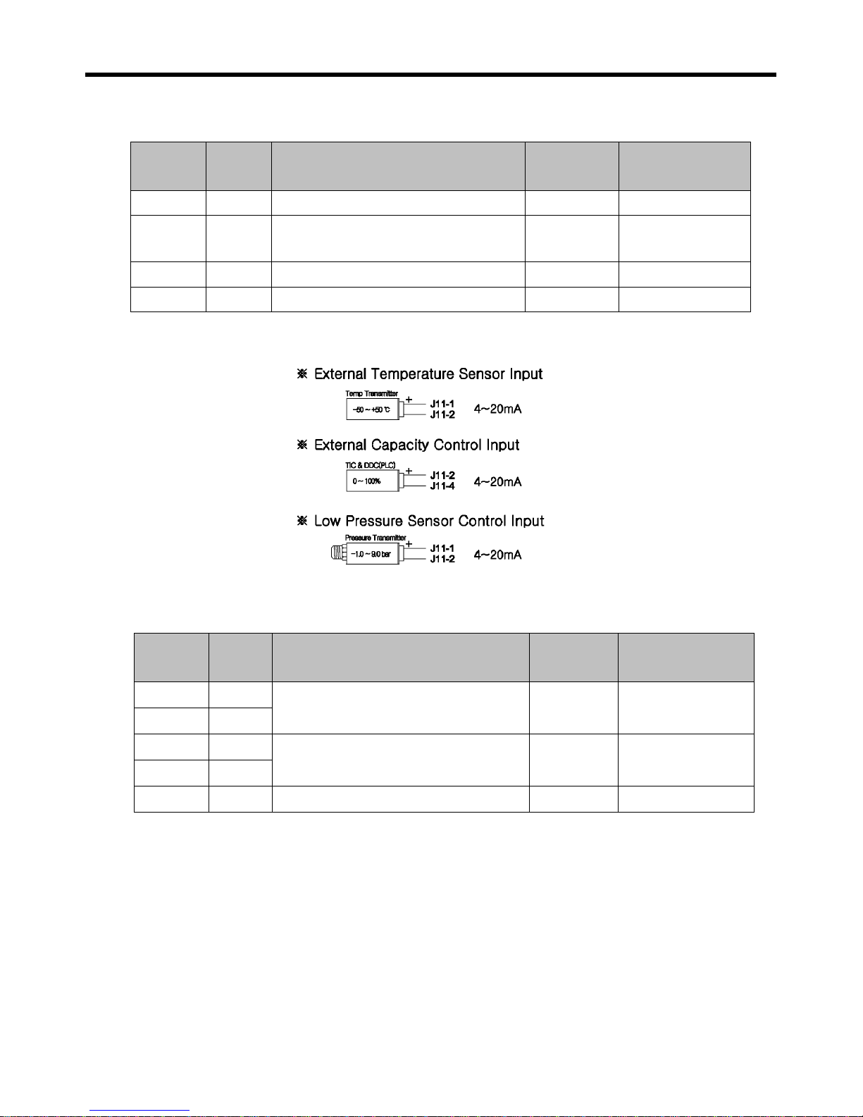
3) ANALOG INPUT SIGNAL
Pin Name Function Type Range
J11.1 +24V Sensor power (+V common)
J11.2 B4
Pressure sensor / temperature
sensor/Capacity control input
4 ~ 20mA Possible to set
J11.3 B5 Pressure sensor / temperature input 4 ~ 20mA Possible to set
J11.4 AVSS 0V common(GND wire of Shield Wire)
Pin Name Function Type Range
J12.1 B1
Inlet port temp-sensor input NTC 5K -40 ~ 70 ℃
J12.2 AVSS
J12.3 B2
Outlet port temp-sensor input NTC 5K -40 ~ 70 ℃
J12.4 AVSS
J12.5 B3 Discharge Gas Temp. Sensor NTC 10K -20 ~ 200 ℃
Page 14
UIC-DX270 Series User’s Manual Rev 1.0
- 14 -
4) ANALOG OUTPUT SIGNAL (OPTIONAL FUNCTION)
Pin Name Function Type
J6.1 Y1 Entrance Temp. Signal (+)
4 ~ 20mA
J6.2 YG1 Entrance Temp. Signal (-)
J6.3 Y2 Exit Temp. Signal (+)
4 ~ 20mA
J6.4 YG2 Exit Temp. Signal (-)
J6.5 Y3 Discharge Gas Temp. Signal (+)
4 ~ 20mA
J6.6 YG3 Discharge Gas Temp. Signal (-)
* Entrance Temperature Signal Range: 4 ~ 20mA (-30.0 ~ 70.0 ℃)
* Exit Temperature Signal Range: 4 ~ 20mA (-30.0 ~ 70.0 ℃)
* Discharge Gas Temperature Signal Range: 4 ~ 20mA (0.0 ~ 200.0 ℃)
Page 15
UIC-DX270 Series User’s Manual Rev 1.0
- 15 -
5) COMMUNICATION SIGNAL (OPTIONAL FUNCTION)
5-1) SYSTEM BUS
Pin Name Function Type
TB1.1 GND -
RS-485
TB1.2 B SYSTEM BUS TRX-
TB1.3 A SYSTEM BUS TRX+
5-2) LOCAL BUS
Pin Name Function Type
TB2.1 GND -
RS-485
TB2.2 B LOCAL BUS TRX-
TB2.3 A LOCAL BUS TRX+
※ Communication feature (System Bus, Local Bus)
① Communication Method : RS-485
② Communication Speed : 4800, 9600, 19200, 384000 BPS, N, 8, 1
③ Communication Protocol : MODBUS RTU MODE
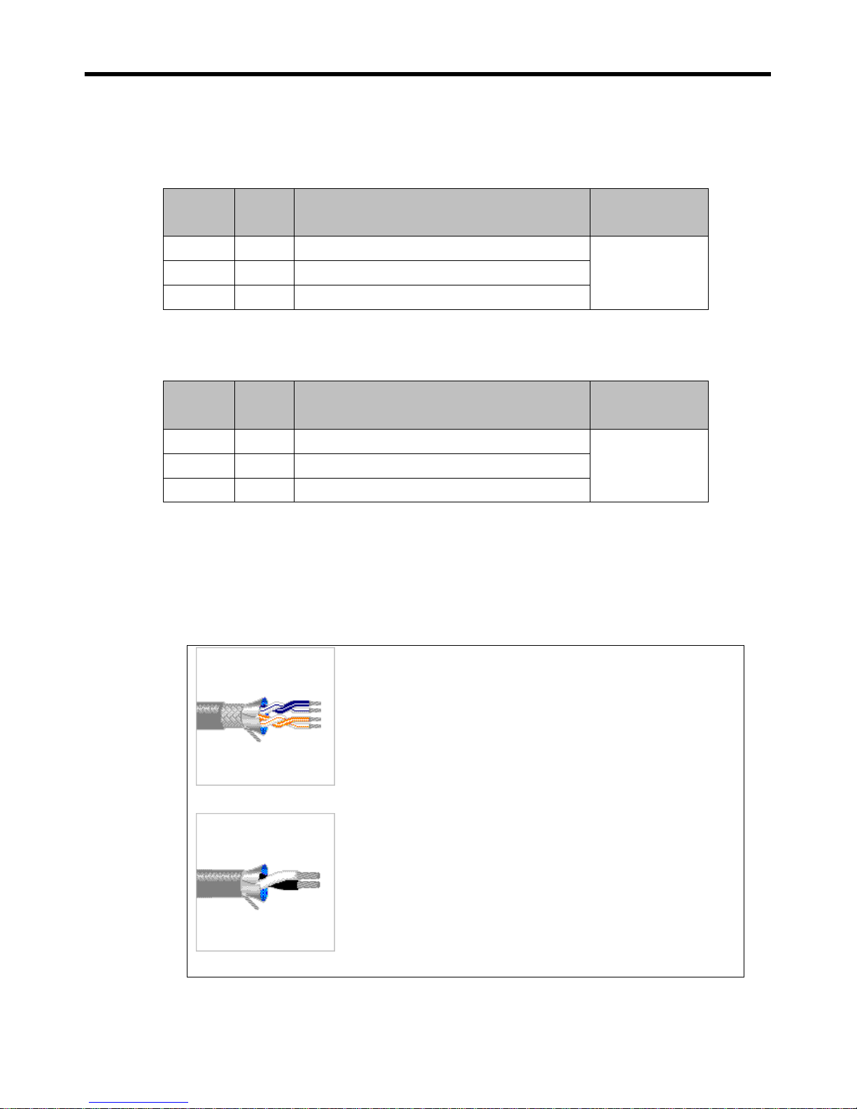
④ Communication Cable(suggested) : BELDEN 9842 or 8761
(9842)
(8761)
BELDEN 9842 Paired- Low Capacitance EIA RS-485
⊙ Number of Pairs: 2
⊙ Total Number of Conductors: 4
⊙ AWG: 24
⊙ Stranding: 7x32
⊙ Conductor Material: TC - Tinned Copper
⊙ Insulation Material: PE - Polyethylene
⊙ Outer Shield Material Trade Name: Beldfoil®
⊙ Outer Shield Material: Aluminum Foil-Polyester Tape/TC –
⊙ Tinned Copper
⊙ Outer Jacket Material: PVC - Polyvinyl Chloride
⊙ Plenum (Y/N): N ⊙Plenum Number: 82842
⊙ Applications: Computer Cables, Low Capacitance EIA RS-485
※ BELDEN 9842 is recommended.
Page 16
UIC-DX270 Series User’s Manual Rev 1.0
- 16 -
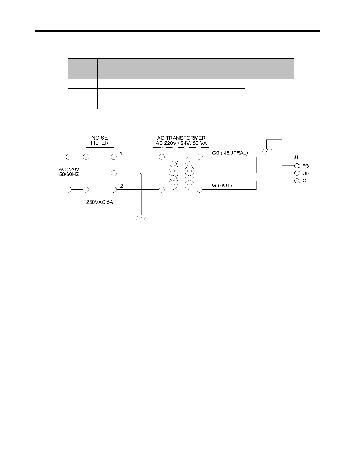
6) CONTROL POWER INPUT
Pin Name Function Type
J1.1 FG FIELD GROUND (CASE SHIELD)
J1.2 G0 AC24V(-) or DC24V(-)
J1.3 G AC24V(+) or DC24V(+)
Page 17
UIC-DX270 Series User’s Manual Rev 1.0
- 17 -
3. COMPOSITION
1) OPERATION AND DISPLAY
1-1) General composition
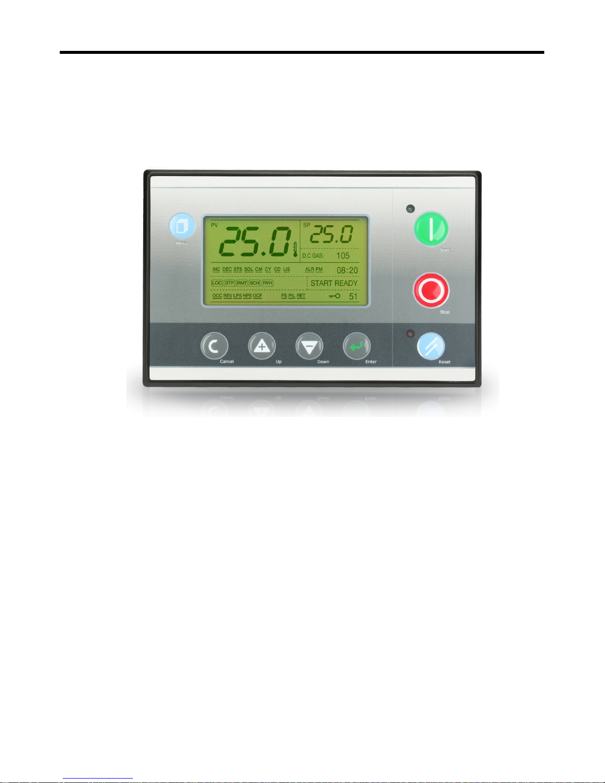
Display: 240 X 128 Graphic LCD (LED BACKLIGHT), LED Green 1, Red 1
Keyboard: 8 main switches
1-2) Operation
Start Switch: Start
Stop Switch: Stop
Reset Switch: Reset during trip
Green lamp: Lamp showing the state of operation
Red lamp: Lamp showing the warning or bad trip
1-3) Setting up program
Choice Switch: Choose the program or value
Down Switch: Control down movement
Up Switch: Control up movement
Menu Switch: Call menu
Return Switch: Return to previous menu or the first menu
Page 18
UIC-DX270 Series User’s Manual Rev 1.0
- 18 -
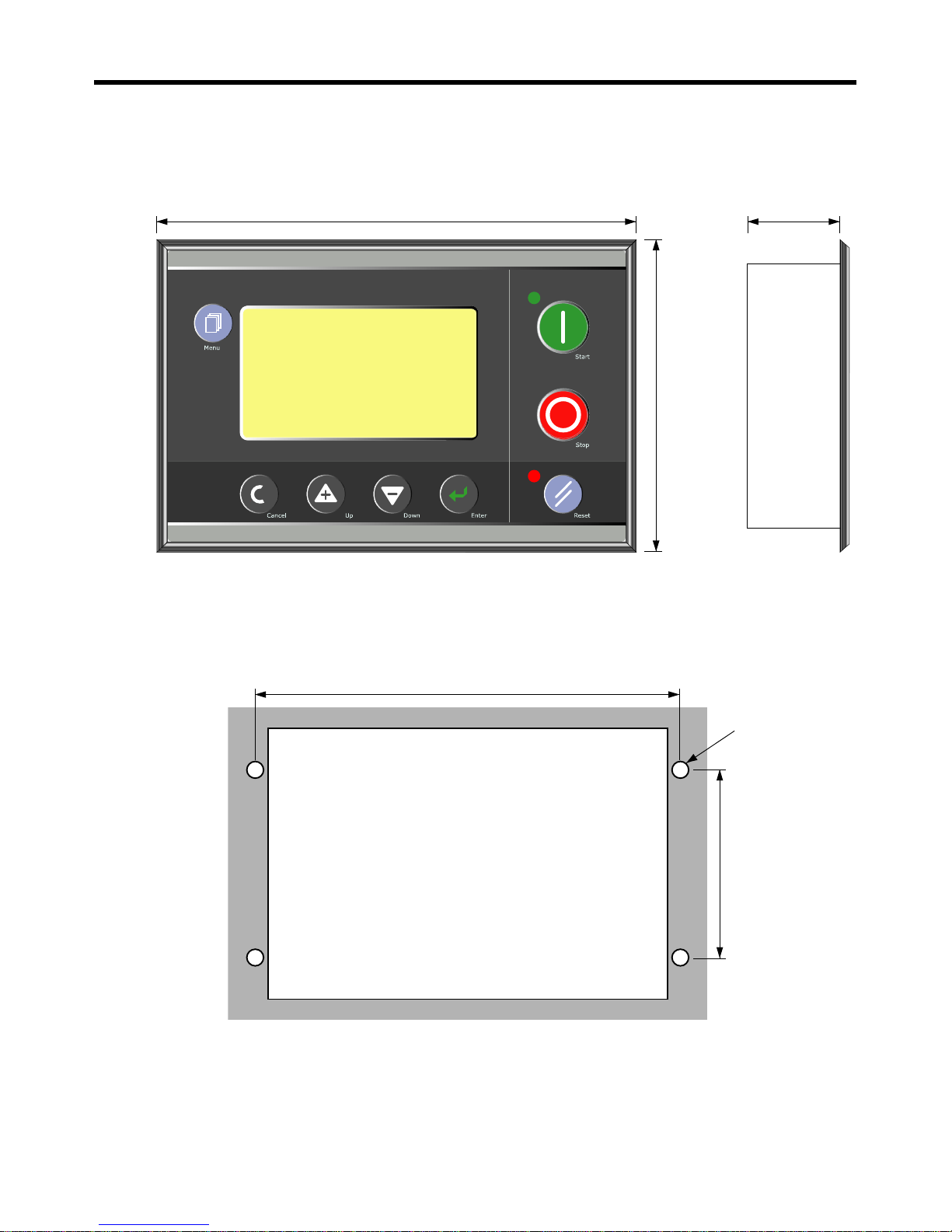
2) OUTLINE DRAWING AND PROCESSING
Page 19
UIC-DX270 Series User’s Manual Rev 1.0
- 19 -
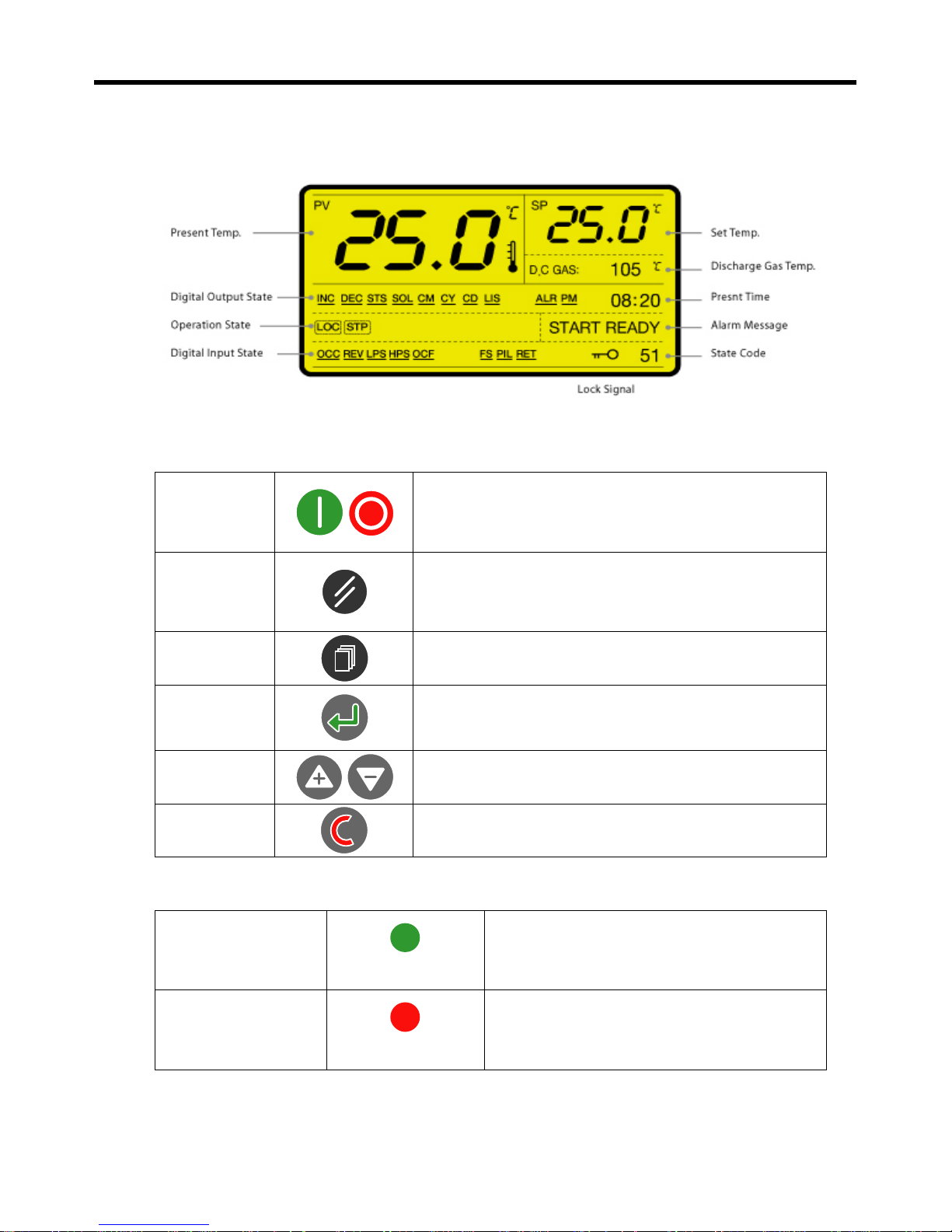
3) DISPLAY OF OPERATING STATE
4) FUNCTION OF AN OPERATION BUTTON
Start/Stop
Star t or Stop
Start when putting the start button
Stop when putting the stop button
Reset
Reset during trip
The Trip having automatic reset function will reset
automatically without putting the button
Menu
Menu button to set for a control and state
Enter
Choose or Save button
Up / Down
Up/ Down
Cancel
Return to previous menu or first menu
5) STATE DISPLAY LAMP
Operation state lamp
Green
Operating ON / OFF
Alarm state lamp
Red
Alarm ON / OFF
Page 20
UIC-DX270 Series User’s Manual Rev 1.0
- 20 -
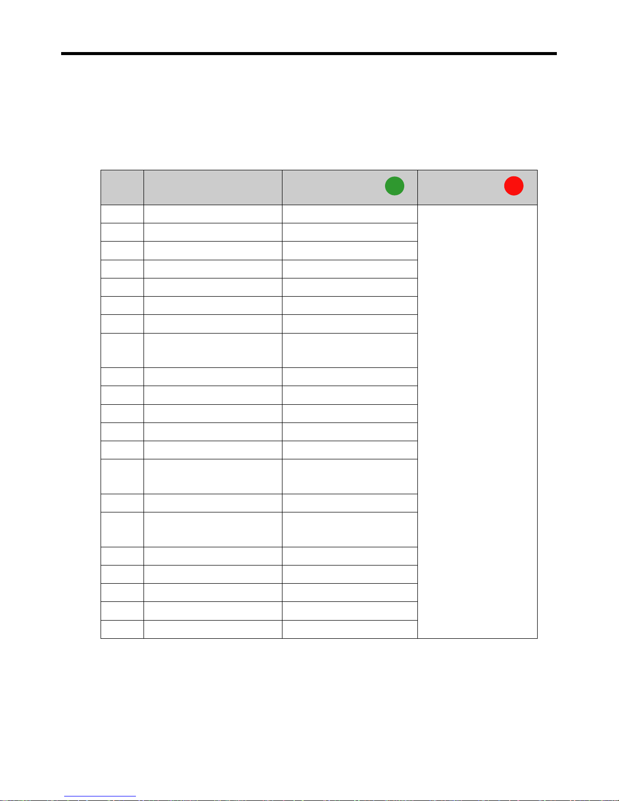
ON: LED is on always, OFF: LED is not on always.
Low speed flickering: ON for 0.5sec, OFF for 0.5sec
High speed flickering: ON for 0.1sec, OFF for 0.1sec
Spot flickering: ON for 0.1sec, OFF for 4sec
State
No.
State
Operation State Lamp
Alarm State Lamp
0 Initialization OFF
Normal: OFF
Trip: High speed
flickering
Alarm: Low speed
flickering
1 Inhibit check OFF
2 Start ready OFF
3 Timer Value Initialization OFF
4 Pump (fan) start delay High speed flickering
5 Pump(fan) start High speed flickering
6 Waiting operation High speed flickering
7
Capacity control value
Initialization
High speed flickering
8 Comp. Operation Delay High speed flickering
9 Comp. Start High speed flickering
10 Start sol off Delay ON
30 Comp. Manual Stop Delay Low speed flickering
31 Pump Down Delay Spot flickering
32 Restart Delay
Low speed flickering /
Spot flickering
40 Pump(Fan)off Delay Spot flickering
41 Pump(Fan) off
Low speed flickering /
Spot flickering
50 Capacity Maintenance Operation ON
51 Capacity Decrease Operation ON
52 Capacity Increase Operation ON
53 Comp. Auto Stop Delay Low speed flickering
99 Shut-Down OFF
Page 21
UIC-DX270 Series User’s Manual Rev 1.0
- 21 -
6) SYMBOL EXPLANATION
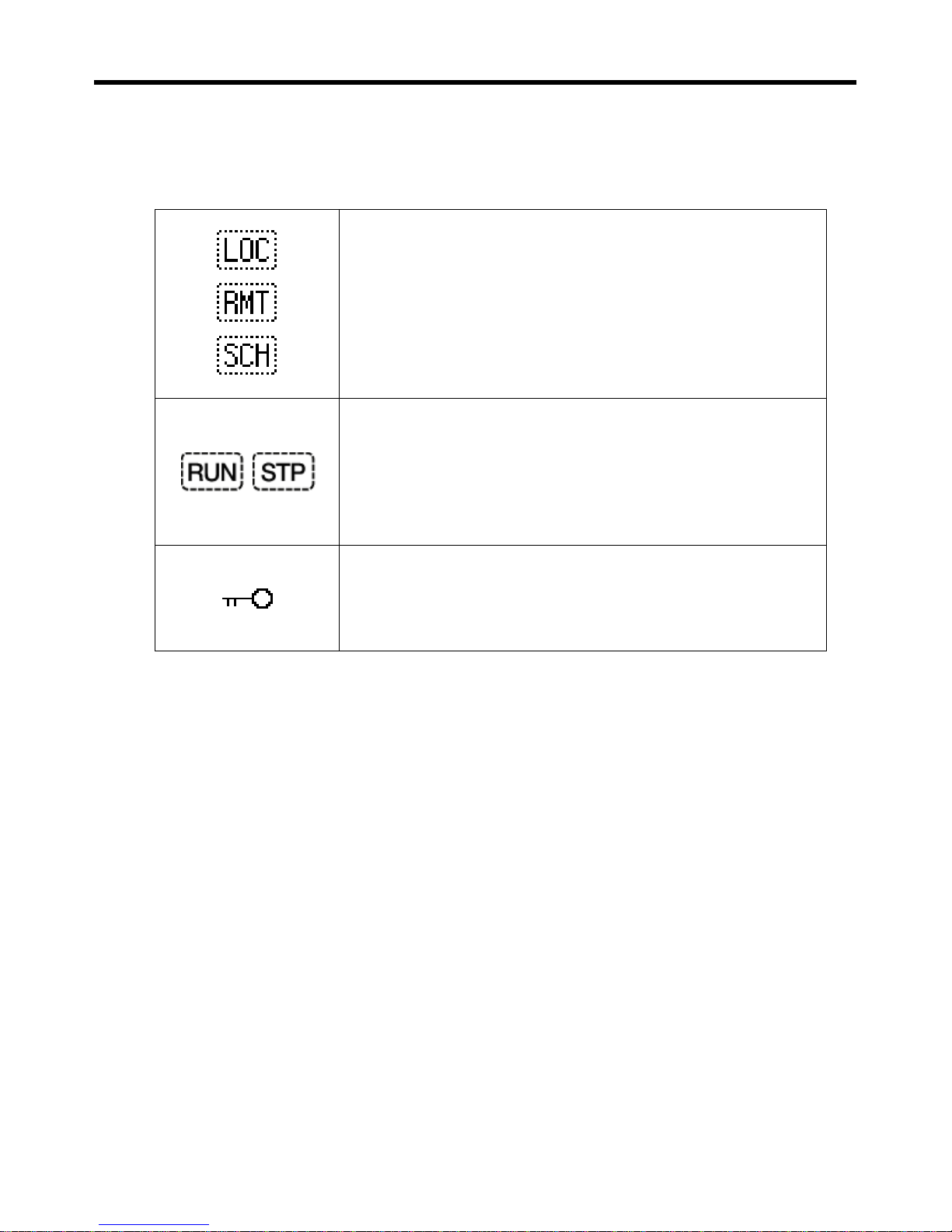
6-1) Equipment state display
Start/Stop Mode State Signal
LOC: Control Start/Stop button on the body
RMT: Remote controlling start/stop
SCH: Pre-organized start/stop on the Operation schedule Setting
Menu
Start/Stop Signal
RUN: Start or in Process
STP: Stop
System Lock Signal
Page 22
UIC-DX270 Series User’s Manual Rev 1.0
- 22 -
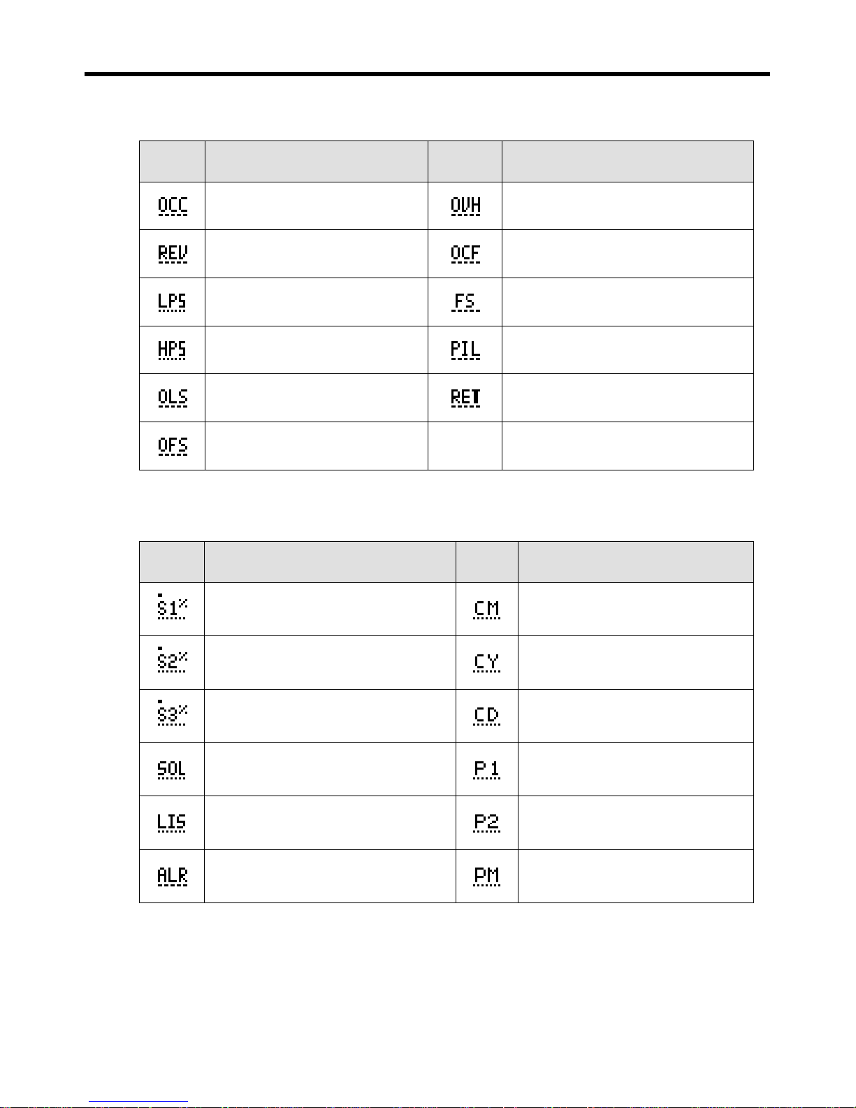
6-2) Digital input signal symbol
Symbol Description Symbol Description
Over-load Main Motor
Over-heat Compressor Signal
Reverse-Phase Main Motor
Condenser Fan Fault Signal
Low-Pressure Switch Signal
Flow Signal -Pump(Fan) Interlock
High-Pressure Switch Signal
Over-load Pump(Fan) Motor
Oil Level Switch Signal
Remote Start/Stop Control
Oil Flow Switch Signal
6-3) Digital output signal symbol
Symbol Description Symbol Description
Load Control Capacity SOL V/V (CR1)
Main Magnetic Contactor
Load Control Capacity SOL V/V (CR2)
Star Magnetic Contactor
Load Control Capacity SOL V/V (CR3)
Delta Magnetic Contactor
Liquid SOL V/V
PW1 Magnetic Contactor
Liquid Injection Sol V/V Control
PW2 Magnetic Contactor
Total Alarm Signal
Pump(Fan)Motor Control Signal
Page 23
UIC-DX270 Series User’s Manual Rev 1.0
- 23 -
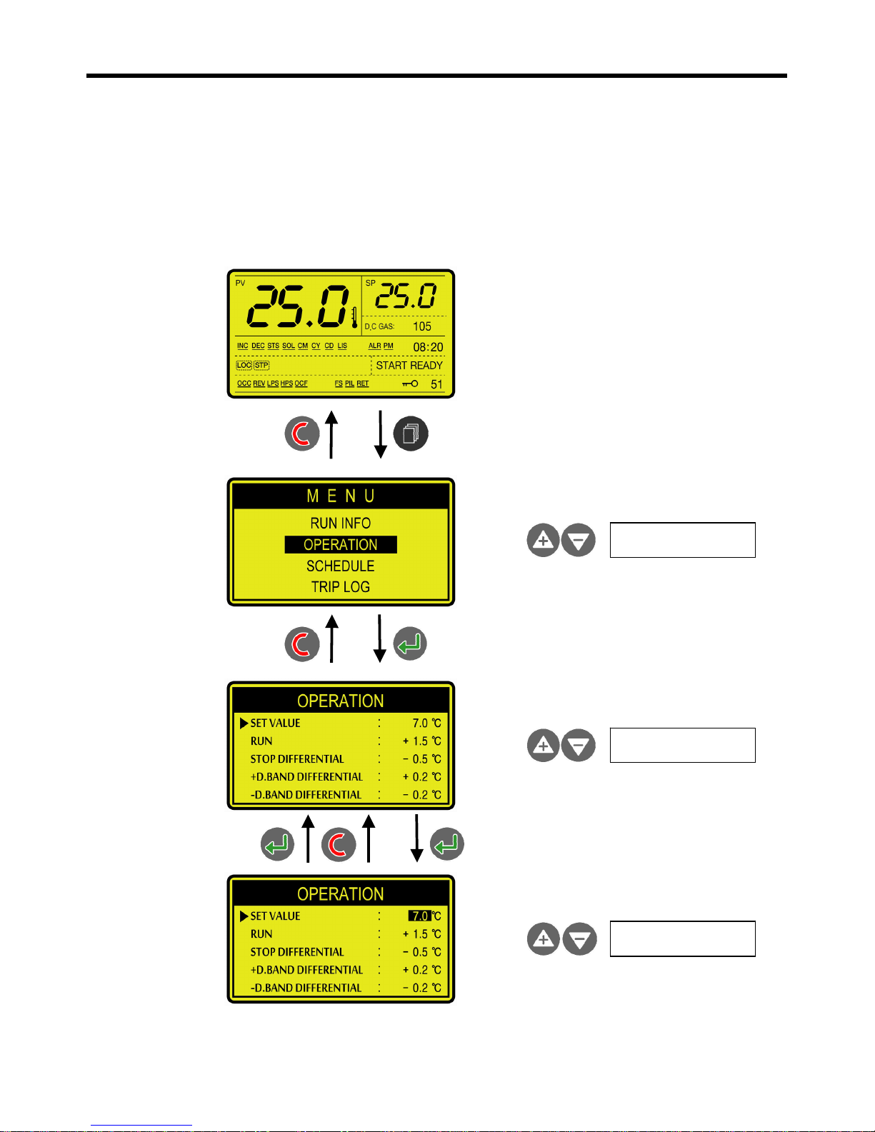
4. MENU COMPOSITION
1) OPERATION AND DISPLAY
Choose main menu
Choose Sub menu
Modify Parameter
Page 24
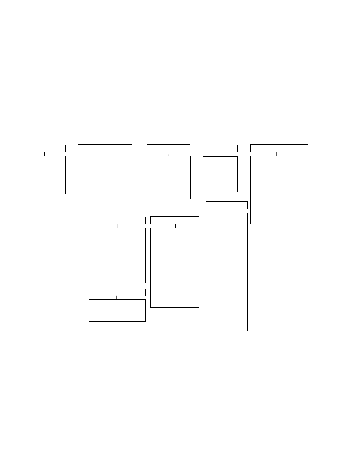
2) MENU STRUCTURE
00: INLET TEMP
01: OUTLET TEMP
02: DISCHARGE GAS
03: RUN HOUR
04: COMPS RUN HOUR
05: COMPS ON/OFF
OPERATION
00: SET VALUE
01: RUN DIFFERENTIAL
02: STOP DIFFERENTIAL
03: 50%CAP.DIFFERENTIAL
04: 75%CAP.DIFFERENTIAL
05: ○+D.BAND DIFFERENTIAL
06: ○-D.BAND DIFFERENTIAL
07: INJECTION SET VALUE
08: INJECTION DIFFERENTIAL
09: LCD BACKLIGHT MODE
SCHEDULE
00:SUN : ON ~ OFF
01:MON : ON ~ OFF
02:TUE : ON ~ OFF
03:WED : ON ~ OFF
04:THU : ON ~ OFF
05:FRI : ON ~ OFF
06:SAT : ON ~ OFF
TRIP LOG
EVENT #1
EVENT #2
EVENT #3
|
EVENT #160
TRIP AND ALARM
00: FLOW SENSING DELAY
01: FLOW SENSING HOLD
02: DISCHARGE TEMP. OVER
03: OUTLET TEMP FREEZE
04: OIL FLOW SENSING DELAY
05: OIL FLOW SENSING HOLD
06: LOW PRESS SENSING DELAY
07: LOW PRESS SENSING HOLD
08: OIL LEVEL SENSING DELAY
09: OIL LEVEL SENSING HOLD
10: CONDENSOR FAULT FUNC.
EXTENTION
00: RUNNING MODE
01: CONTROL SOURCE
02: STEP DELAY TIME
03: STEP DELAY TIME (STRAT)
04: COMP. STRAT DELAY TIME
05: COMP. AUTO STOP DELAY
06: COMP. STOP DELAY TIME
07: START SOL OFF DELAY
08: PUMP(FAN) OFF DELAY
09: Y/D,P/W CHANGE TIME
10: PUMP-DOWN DELAY TIME
11: BLACKOUT RETURN FUNC.
CALIBRAITION
00: INLET TEMP SENSOR CAL.
01: OUTLET TEMP SENSOR CAL
02: DISCHARGE SENSOR CAL
TEST MODE
00: MANUAL TEST MODE
01: CR1 CAPACITY SOL
02: CR2 CAPACITY SOL
03: CR3 CAPACITY SOL
04: MAIN LIQUD SOL
05: COMPS MM•PW1
06: COMPS MY•PW2
07: COMPS MD
08: INJECTION SOL
09: SPARE
10: RUN STATE
11: TOTAL ALARM
12: PUMP(FAN) CONTROL
FACTORY SE T
00: SELF TEST
01: LOG CLEAR
02: INFO CLEAR
03: B1 INPUT
04: B2 INPUT
05: B3 INPUT
06: B4 INPUT
07: B5 INPUT
08: B4 4mA SET
09: B4 20mA SET
10: B5 4mA SET
11: B5 20mA SET
12: Y1 4mA SET
13: Y1 20mA SET
14: Y2 4mA SET
15: Y2 20mA SET
16: Y3 4mA SET
17: Y4 20mASET
18: ADC FILTER
19: DAC FILTER
CONFIGURE
00: COMP START METHOD
01: INLET TEMP SENSOR
02: OUTLET TEMP SENSOR
03: DISCHARGE TEMP SENSOR
04: INJECTION SOL TYPE
05: START CAPCITY METHOD
06: 50% CAPCITY METHOD
07: 75% CAPCITY METHOD
08: 100% CAPCITY METHOD
RUN INFO
Page 25
3) MENU ACCESS LEVEL
Access Level
USER 2
(CODE = 0009)
SERVICE 1
(CODE = 0100)
SERVICE 2
(CODE = 0119)
SERVICE 3
(CODE = ****)
Accessible
Menu
1. Run info.
2. Operation
3. Trip log
4. Calibration
1. Run info.
2. Operation
3. Schedule
4. Trip log
5. Trip and alarm
6. Extention
7. Configure
8. Test mode
1. Run info.
2. Operation
3. Schedule
4. Trip log
5. Trip and Alarm
6. Extention
7. Configure
8. Calibration
9. Test mode
1. Run info.
2. Operation
3. Schedule
4. Trip log
5. Trip and Alarm
6. Extention
7. Configure
8. Calibration
9. Test mode
10. Factory set
Maintenance
Time
1 min. 10 min. 30 min. 1 hour
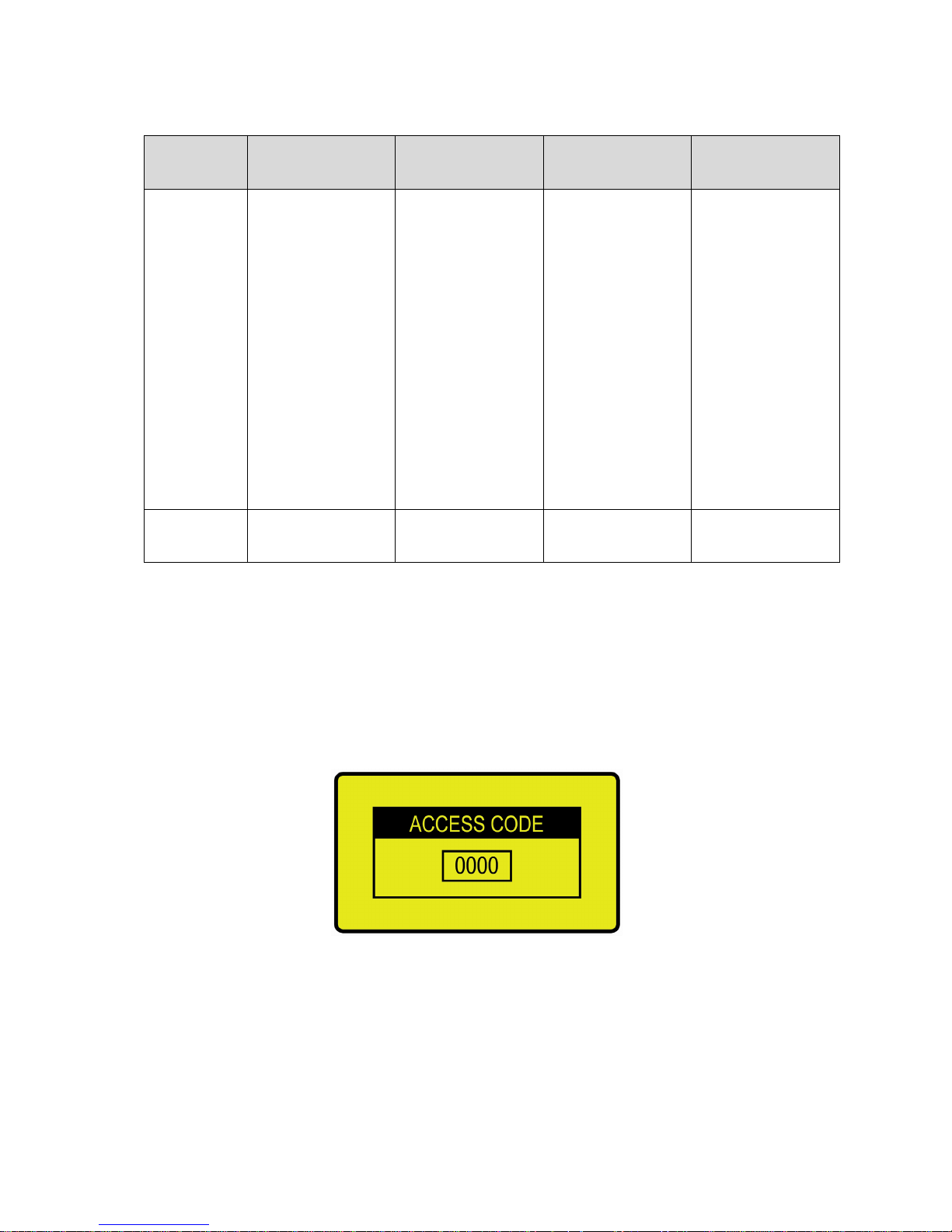
When changing Access Level Mode, make locked by putting Cancel button for 3 sec.
1) If putting [Menu] on operating display, it shows access code input display below.
(If putting [Menu] during supporting time, it does not ask Access Code.)
2) After input Access Code by [Up]/[Down] key, put [Enter] and then, convert to Menu display.
<Access code input screen>
3) Before maintenance time, put [Cancel] key for 3 min. for Locked Mode.
Page 26
UIC-DX270 Series User’s Manual Rev 1.0
- 26 -
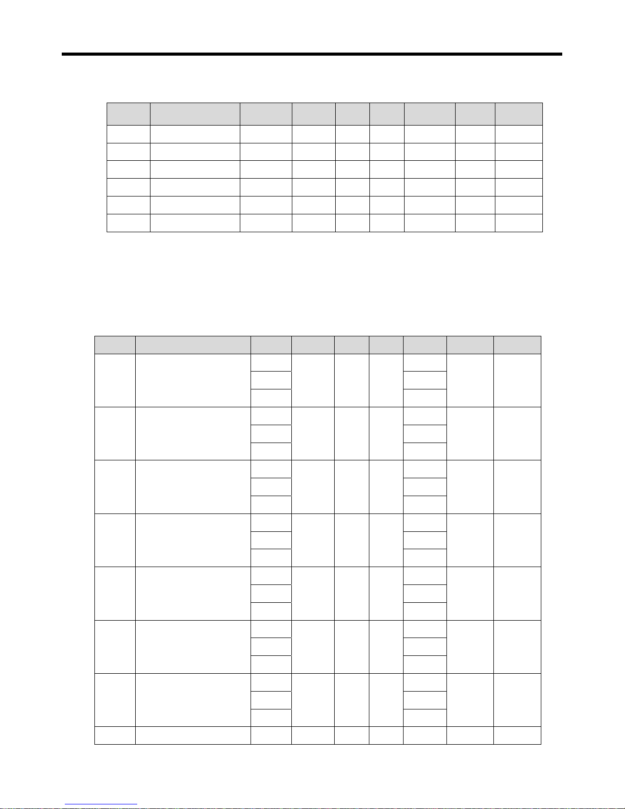
4) RUN INFORMATION
Item Description Units Step Min Max Default View Access
000 Inlet Temp. ℃ 0.1 -40.0 70.0 View only USER 1 -
001 Outlet Temp. ℃ 0.1 -40.0 70.0 View only USER 1 -
002 Discharge Gas Temp. ℃ 1 0 180 View only USER 1 -
003 Run hour h 1 0 99999 0 USER 1 SVC 2
004 Comps run hour h 1 0 99999 0 USER 1 SVC 2
005 Comps on/off number 1 0 99999 0 USER 1 SVC 2
1) Over 99999 Operation Time or Number, it is initialized ‘0’ automatically.
2) Operation Time or Number could be changed over Service Level 2.
5) OPERATION
Item Description Units Step Min Max Default View Access
100
Set value
℃
0.1 -99.9 99.9
7.0
USER2 USER2Bar 2.0
% 20.0
101
Run differential
℃
0.1 +0.1 +50.0
+5.0
USER2 USER2Bar +2.0
% +30.0
102
Stopping differential
℃
0.1 -50.0 0.0
0.0
USER2 USER2Bar 0.0
% 0.0
103
50% cap.differential
℃
0.1 0.0 +50.0
+1.0
SVC1 SVC1 Bar +0.5
% +10.0
104
75% cap.differential
℃
0.1 0.0 +50.0
+2.0
SVC1 SVC1 Bar +1.5
% +20.0
105
○+D.Band differential
℃
0.1 0.0 +20.0
+0.2
SVC1 SVC1
Bar +0.1
% +2.0
106
○-D.Band differential
℃
0.1 -20.0 0.0
-0.2
SVC1 SVC1
Bar -0.1
% -2.0
107
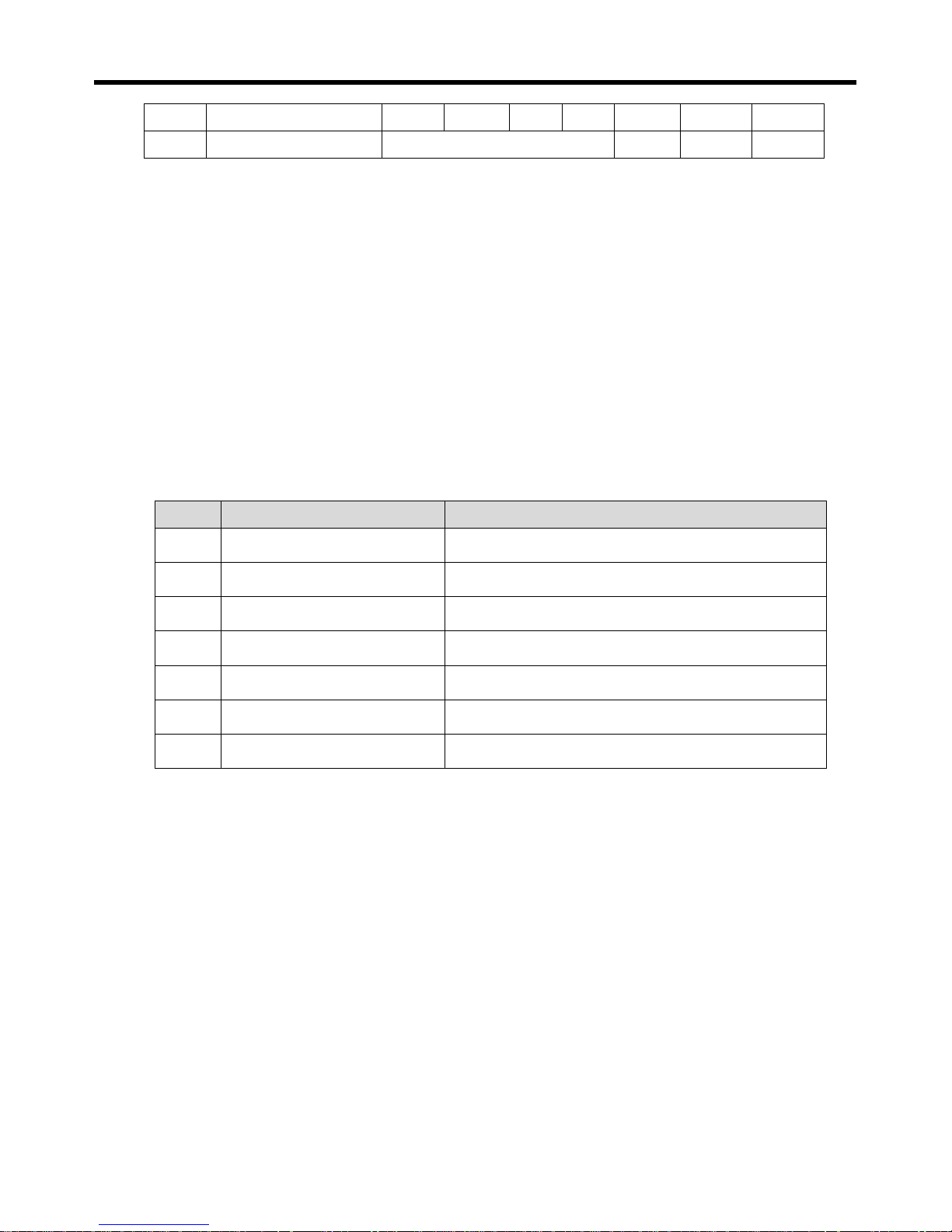
Injection set value. ℃ 1 0 180 100 SVC1 SVC1
Page 27
UIC-DX270 Series User’s Manual Rev 1.0
- 27 -
108
Injection differential ℃ 1 -50 -1 -10 SVC1 SVC1
109
LCD backlight Mode On / Off Off USER2 USER2
※ According to the control objects that set up in operation menus, Unit (℃,bar,%) is changed.
1) Set value: Input a standard of freezer control.
2) Run differential: Input condition that a freezer operate.
(ex, 7.0+5.0=12.0 If it is a more than 12, be operating start.)
3) Stopping differential: Input condition that a freezer stops.
(ex, 7.0-0.0=7.0 If it is 7 or below, be operating stop)
4) Injection control temperature and differential: Input a temperature control section of a inject valve.
(ex, Be OFF . at ON, 90 degrees or below at 100 degrees ideal)
5) LCD backlight mode: On(always On), Off(In case of the alarm On, Be automatic off. On in case of
button operation 60 seconds later)
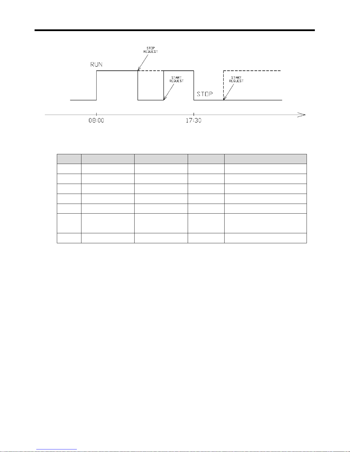
6) SCHEDULE OPERATION
Item Description RUN ~ STOP
400 SUN 00 : 00 ~ 00 : 00
401 MON 08 : 30 ~ 18 : 30
402 TUE 08 : 30 ~ 18 : 30
403 WED 08 : 30 ~ 18 : 30
404 THU 08 : 30 ~ 18 : 30
405 FRI 08 : 30 ~ 18 : 30
406 SAT 08 : 30 ~ 12 : 30
※ It is displayed when setting to reservation Operation from expanded operation
.
1) Operate at the set time, stop at the set time.
2) Equipment is operating automatically during operating time and stops during stop time.
3) If it does not need to operate on exact day, set Operating Time and Stop Time equally.
4) If Operating Time is after stop Time, equipment does not work.
5) During schedule Operation, it is possible to control with [Operation] key and [Stop] key.
(Picture below)
6) After Stop Time, it does not operate by putting [Operation] key.( Picture below)
7)
Page 28
UIC-DX270 Series User’s Manual Rev 1.0
- 28 -
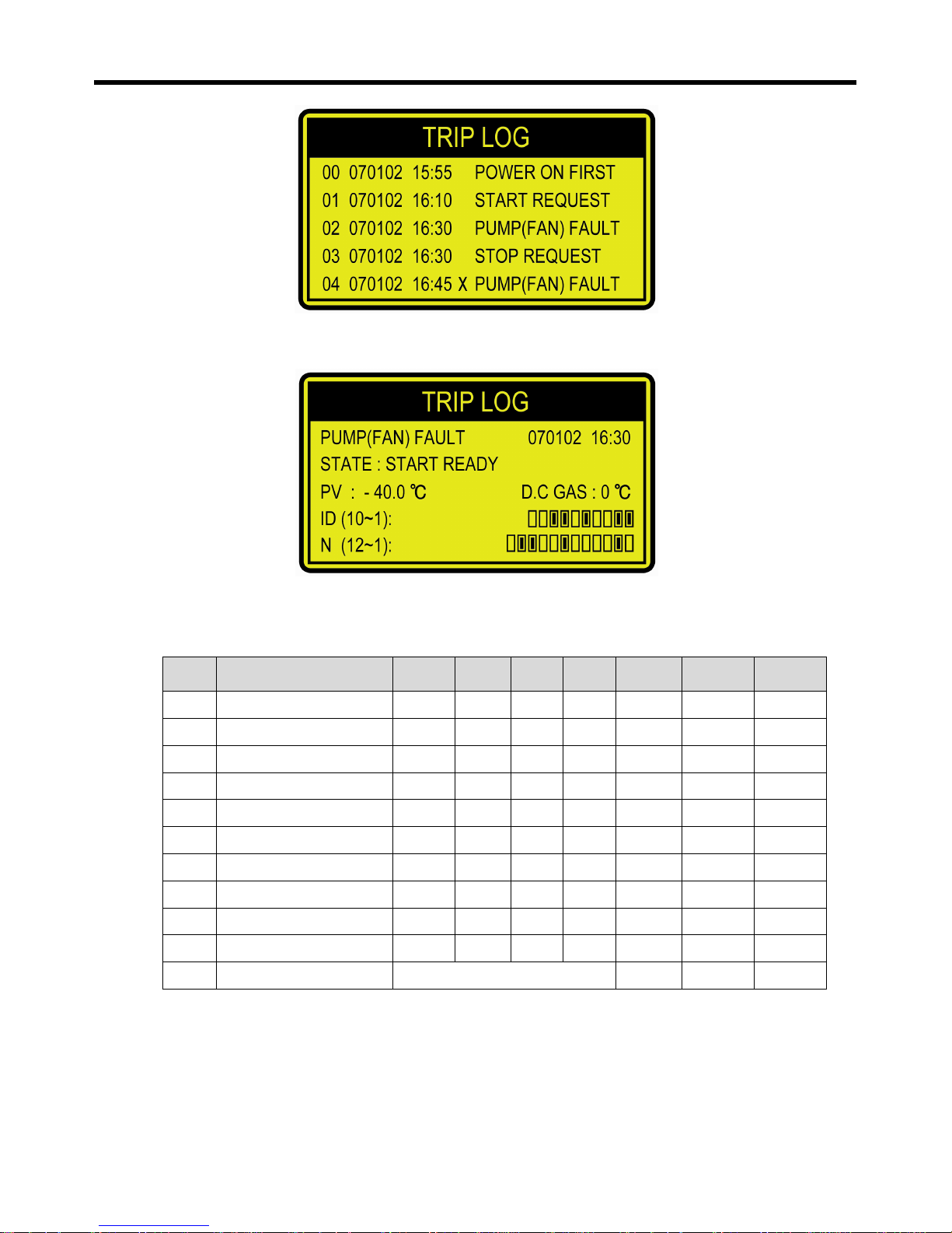
7) TRIP LOG
Item Date Time Occur/Reset Event
1 Y Y / M M / D D H H : M M ( X ) The name of Trip warning #1
2 Y Y / M M / D D H H : M M ( X ) The name of Trip warning #2
3 Y Y / M M / D D H H : M M ( X ) The name of Trip warning #3
4 Y Y / M M / D D H H : M M ( X ) The name of Trip warning #4
5 Y Y / M M / D D H H : M M ( X ) The name of Trip warning #5
|
|
|
|
|
|
|
|
|
|
160 Y Y / M M / D D H H : M M ( X ) The name of Trip warning #160
※ It is not possible to modify or erase log.
① If Trip Warning occurs (cancel), event date and the name of trip warning is saved in
nonvolatile memory.
② Maximum is 160, it is deleted and saved previous events over 160 events.
③ When occurring, date, time, event (trip warning) are recorded, when canceling, ‘X’ is showed
next to time.
④ If putting [Enter], Operation state Code, Exit Pressure, Exit Temp., and Surrounding Temp. Are
showed.
⑤
Page 29
UIC-DX270 Series User’s Manual Rev 1.0
- 29 -
The state of equipment during trip
8) TRIP AND ALARM
Item Description Units Step Min Max Default View Access
400 Flow sensing delay
Sec. 1 0 300 60 SVC1 SVC1
401 Flow sensing hold
Sec. 1 0 300 5 SVC1 SVC1
402 Discharge temp over ℃ 1 50 180 115 SVC1 SVC1
403 Outlet temp freeze
℃ 1 -99 99 3 SVC1 SVC1
404 Oil flow sensing delay
Sec. 1 0 300 60 SVC1 SVC1
405 Oil flow sensing hold Sec. 1 0 300 0 SVC1 SVC1
406 Lo press sensing delay
Sec. 1 0 300 60 SVC1 SVC1
407 Lo press sensing hold
Sec. 1 0 300 5 SVC1 SVC1
408 Oil level sensing delay Sec. 1 0 300 60 SVC1 SVC1
409 Oil level sensing hold
Sec. 1 0 300 5 SVC1 SVC1
410 Condensor fault func.
Off / On On SVC1 SVC1
1) Flow state error fault
Stream detection delay time: Start for perceiving after delay time since a pump(fan) was
operated a detection of a stream detection switch. (Be always detections if set up in 0
seconds.)
Page 30
UIC-DX270 Series User’s Manual Rev 1.0
- 30 -
Stream detection operation time: Shall be OFF state during action time, and input of a stream
detection switch perceives.( If it is 0 seconds, do not perceive)
2) Outlet temp freeze: A trip function runs hereafter the freezing temperature that exit temperature is
excessive.
3) Oil flow error fault
Oil flow delay: Start for perceiving after delay time since a freezer was driven a detection of
an oil stream switch. (( Be always detections if set up in 0 seconds)
Oil flow operation time: Shall be OFF state during action time, and input of an oil stream
switch perceives. (If it is 0 seconds, do not perceive)
4) Lo press error fault
Lo press sensing delay: Start for perceiving after delay time since a freezer was driven a
detection of a low pressure switch. (Be always detections if we set up in 0 seconds)
Lo press sensing time: Shall be OFF state during action time, and input of a low pressure
switch perceives (If it is 0 seconds, do not perceive)
5) Oil level error fault
Oil level delay time: Start for perceiving after delay time since a freezer was driven a
detection of an oil level switch.( Be always detections if we set up in 0 seconds)
Oil level operation time: Shall be OFF state during action time, and input of an oil level switch
perceives. (If it is 0 seconds, do not perceive)
6) Condensor fault func.: If it is an air cooling formula, select whether or not there is by condensor
Fan alarm use.
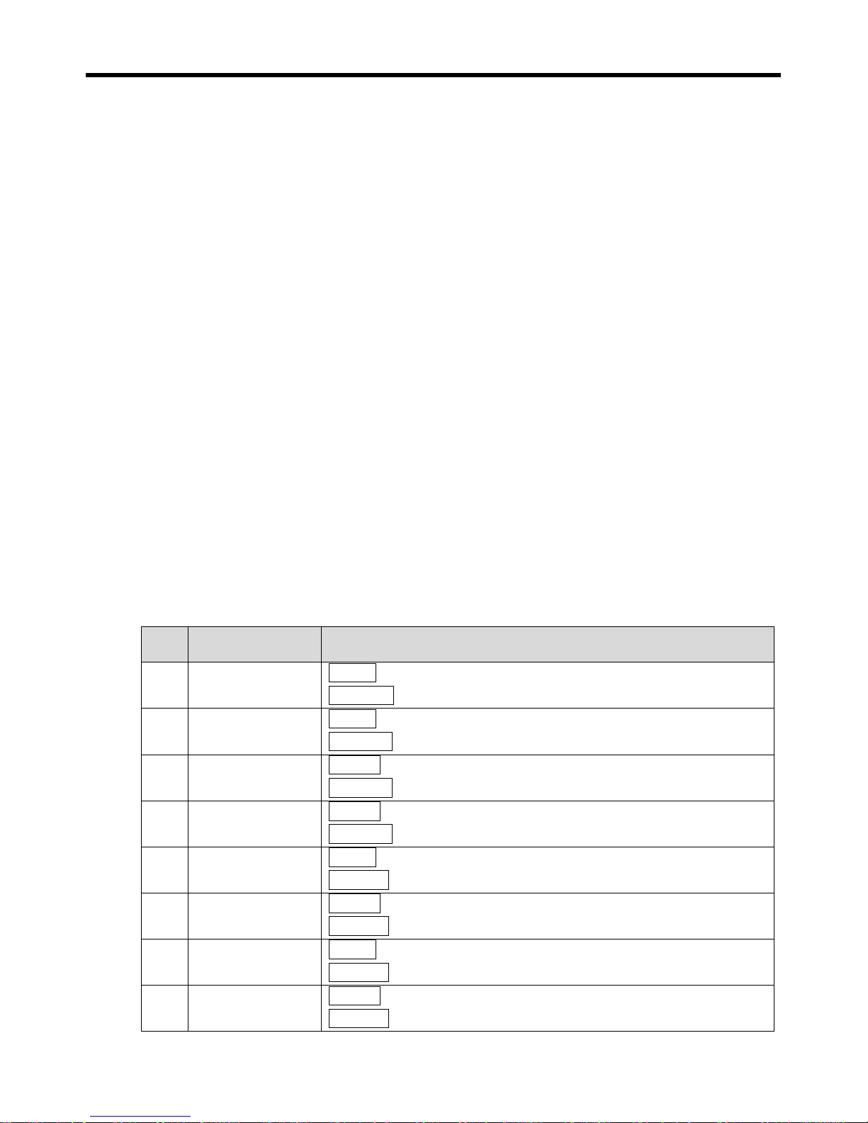
8-1) Trip alarm message
Item Description Detect condition
1
Outlet sens. flt.
Detection If an error occurred to an exit direction temperature sensor (Breaking of wire)
Cancellation If an exit direction temperature sensor is normal
2
Dc gas sens. flt.
DetectionIf an error occurred to an exit direction discharge-gas sensor (Breaking of wire)
Cancellation If an exit direction discharge-gas sensor is normal
3
Pump(fan) fault
Detection [Digital signal input:ID9:pump(fan)interlock] signal OFF
Cancellation [Digital signal input:ID9: pump(fan)interlock] signal ON
4
Flow fualt
Detection [Digital signal input:ID8:flow] signal OFF
Cancellation [Digital signal input:ID8:flow] signal ON
5
Comp ocr
Detection[Digital signal input:ID1: Be detections to over-current of a freezer] signal OFF
Cancellation[Digital signal input:ID1: Be detections to over-current of a freezer] signal ON
6
Phase fault
Detection [Digital signal input:ID2: Be detections to back current of a freezer] signal OFF
Cancellation[Digital signal input:ID2: Be detections to back current of a freezer] signal ON
7
Low press fault
Detection[Digital signal input:ID3: A low pressure switch of a freezer] signal OFF
Cancellation[Digital signal input:ID3: A low pressure switch of a freezer] signal ON
8
Hi press fault
Detection [Digital signal input:ID3: A high pressure switch of a freezer] signal OFF
Cancellation[Digital signal input:ID3: A high pressure switch of a freezer] signal ON
Page 31
UIC-DX270 Series User’s Manual Rev 1.0
- 31 -
9
Dc gas over-temp
DetectionDischarge-gas temp. > [Trip alarm setting: Excessive temperature setting
of discharge-gas]
CancellationDischarge-gas temp <= [Trip alarm setting: Excessive temperature setting
of discharge-gas] - 5℃
10
Outlet freeze
Detection exit temp. < [Trip alarm setting: An excessive freezing temperature alarm of
an exit]
Cancellationexit temp. >= [Trip alarm setting:
An excessive freezing temperature alarm
of an exit] + 2℃
11
Cond-fan fault
Detection [Digital signal input:ID7:condenser error] signal OFF
Cancellation [Digital signal input:ID7: condenser error] signal ON
12
Inlet sens. fault
DetectionIf an error occurred to an entrance direction temperature sensor
(Breaking of wire)
Cancellation If an entrance direction temperature sensor is normal
13
Comp int fault
Detection[Digital signal input:ID6: An overheating signal of a freezer] signal OFF
Cancellation[Digital signal input:ID6: An overheating signal of a freezer] signal ON.
14
Press sens. fault
Detection If an error occurred to a pressure sensor (Breaking of wire)
Cancellation If a temperature sensor is normal
15
Ext. t-sens fault
Detection If An outdoor temperature sensor is an error (Breaking of wire).
Cancellation If An outdoor temperature sensor is normal
16
Cap. Signal fault
Detection If An external capacity signal is an error.
Cancellation If An external capacity signal is normal
17
System fault
Detection if a control Parameter value was changed suddenly
Cancellation Control Parameter after confirmation
※ Fault message occurred in is released after removing the cause of corresponding Fault
if we press a RESET key.
Page 32
UIC-DX270 Series User’s Manual Rev 1.0
- 32 -
9) EXTENT OPERATING SET
Item Description Units Step Min Max Default View Access
500 Running mode -
LOCAL / REMOTE CONTROL /
RESERVATION
LOCAL SVC1 SVC1
502 Control source - IN / OUT / B4 / E-B4 / P-B4 OUT SVC1 SVC2
503 Step delay time Sec. 1 0 999 10 SVC1 SVC2
504 Step delay time(start) Sec. 1 0 999 180 SVC1 SVC2
507 Comp. start delay time Sec. 1 0 600 5 SVC1 SVC2
508 Comp. restart delay time Min. 1 0 30 5 SVC1 SVC2
509 Comp. auto stop delay Sec. 1 0 600 5 SVC1 SVC2
510 Comp. stop delay Sec. 1 0 600 5 SVC1 SVC2
511 Start sol off delay Sec. 1 0 600 30 SVC1 SVC2
512 Pump(fan) off delay Min. 1 0 30 0 SVC1 SVC2
513 Y/D,P/W change time Sec. 0.1 0.1 30.0 5.0 SVC1 SVC2
514 Pump-down set Sec. 1 0 600 0 SVC1 SVC2
515 Blackout return func. - OFF / ON ON SVC1 SVC2
516 System address setting** - 1 1 128 1 SVC1 SVC2
517 Local address setting** - 1 1 128 1 SVC1 SVC2
518 System communication speed
**
4800, 9600, 19200, 38400
9600 USER2 USER2
519 Local communication speed ** - 9600 USER2 USER2
**
The function that can communicate with was installed, and be marked.
1) Running mode: local(Use keypad of a controller), remote control(Use digital input ID10),
reservation (Use schedule operation)
2) Control source : control source setting (IN: entrance temperature, OUT: exit temperature, B4:
outdoor temperature , E-B4: outdoor capacity, P-B4: low pressure control) B4, E-B4, P-B4 is
4~20mA input style
3) Comp. start delay time: ON does liquid stream valve and operation valve, and a compressor sets
up time of operation
4) Comp restart delay time: Compressor set up after OFF, and it is possible a driving compressor
since time was passed
5) Comp. auto stop delay: A compressor sets up the time that is condition that is OFF, delay time (By
temperature)
6) Comp. stop delay: The time that is condition that a compressor is OFF, delay time (By keypad,
digital input ID10 etc)
7) Start sol off delay: ON sets later up time to operating-valve a compressor until select OFF
8) Pump(fan) off delay: Set up circulation driving time of pump(fan)
9) Pump-down set: Set the pump-down time of freezer
10) Blackout return func.:After a stoppage of power supply, set return or not previous Operation/stop
Page 33
UIC-DX270 Series User’s Manual Rev 1.0
- 33 -
10) CONFIGURE
※ Should change a setting number since a grasp called exactly a characteristic.
※ Perfection shall be stopped, and setting is possible equipment.
Item Description Units Step Min Max Default View Access
612 Comp. start method Direct / YDelta / PWinding YDelta SVC1 SVC2
613 Inlet temp sensor
OFF / ON
OFF SVC1 SVC2
614 Outlet temp sensor ON SVC1 SVC2
615 Discharge temp sensor ON SVC1 SVC2
617 Injection sol type OFF / ON ON SVC1 SVC2
621 Start capcity method
1 - CR1:OFF, CR2:OFF, CR3:OFF
2 - CR1:OFF, CR2:OFF, CR3:ON
3 - CR1:OFF, CR2:ON, CR3:OFF
4 - CR1:OFF, CR2:ON, CR3:ON
5 - CR1:ON, CR2:OFF, CR3:OFF
6 - CR1:ON, CR2:OFF, CR3:ON
7 - CR1:ON, CR2:ON, CR3:OFF
8 - CR1:ON, CR2:ON, CR3:ON
9 – NONE
2 SVC1 SVC2
622 50% capcity method 3 SVC1 SVC2
623
75% capcity method
5 SVC1 SVC2
624 100% capcity method 1 SVC1 SVC2
1) Compressor maker selection: Set up a control method.
A capacity control method, a compressor operating method is set up automatically.
2) Select compressor operating method: Select operating method.
3) Entrance/exit/discharge-gas temperature sensor selection: Set up whether or not there is by a
port of the temperature sensor which it was installed and use.
Use injection valve: Set up whether or not there is by use of a liquid spray valve.
4) Configuration of an action to control capacity: operating/50%/75%/100% Select valve
configuration of an action to control capacity.
5) capacity control does not call if we set up to NONE in Configuration of an action Relevant
to control capacity.
Page 34
UIC-DX270 Series User’s Manual Rev 1.0
- 34 -
11) CALIBRATION
Item Description Units Step Min Max Default View Access
700
Inlet temp sensor cal
℃ 1 -20.0 +20.0 0.0 USER 2 USER 2
701
Outlet temp sensor cal
℃ 1 -20.0 +20.0 0.0 USER 2 USER 2
702
Discharge-gas temp cal
℃ 1 -20.0 +20.0 0.0 USER 2 USER 2
703
Press sensor cal
Bar 1 -20.0 +20.0 0.0 USER 2 USER 2
704
Press sensor range lo
Bar 1 -1 +100 0 USER 2 USER 2
705
Press sensor range hi
Bar 1 -1 +100 30 USER 2 USER 2
706
Exit temp sensor cal
℃ 1 -20.0 +20.0 0.0 USER 2 USER 2
707
Exit temp sensor lo
℃ 1 -50 +200 -20 USER 2 USER 2
708
Exit temp sensor hi
℃ 1 -50 +200 80 USER 2 USER 2
1) Inlet temp sensor cal: Input a revision price of an entrance temperature sensor.
2) Outlet temp sensor cal: Input a revision price of an exit temperature sensor.
3) Discharge-gas temp cal: Input a revision price of a discharge-gas temperature sensor.
4) Press sensor range lo: Input an inferior limit price of a pressure sensor.
5) Press sensor hi: Input an upper limit price of a pressure sensor.
Page 35
UIC-DX270 Series User’s Manual Rev 1.0
- 35 -
12) TEST MODE
Accessible right: SVC1, Changeable right: SVC2
Item Description Units Step Min Max Default
1000
Manual test mode
- ON / OFF OFF
1001
Cr1 capacity sol
- ON / OFF OFF
1002
Cr2 capacity sol
- ON / OFF OFF
1003
Cr2 capacity sol
- ON / OFF OFF
1004
Main Liquid sol
- ON / OFF OFF
1005
Comp MM•PW1
- ON / OFF OFF
1006
Comp MY•PW2
- ON / OFF OFF
1007
Comps MD
- ON / OFF OFF
1008
Injection sol
- ON / OFF OFF
1009
Spare
- ON / OFF OFF
1010
Run state
- ON / OFF OFF
1011
Total alarm
- ON / OFF OFF
1012
Pump(Fan) control
- ON / OFF OFF
1) Manual operation is possible in stop state only.
2) MS (Star Magnet) and MD(Delta Magnet) cannot operate at a same time.
Page 36
UIC-DX270 Series User’s Manual Rev 1.0
- 36 -
13) FACTORY SET
※ This is the set mode when delivered thus, please understand exactly and then, changes it
.
Item Description Units Step Min Max Default View Access
900
Self test
NO / YES NO SVC2 SVC3
901
Log clear
NO / YES NO SVC2 SVC3
902
Info clear
NO / YES NO SVC2 SVC3
903
B1 Input
Only View
997 SVC2 -
904
B2 Input
280 SVC2 -
905
B3 Input
997 SVC2 -
906
B4 Input
280 SVC2 -
907
B5 Input
997 SVC2 -
908
B4 4mA set
1 0 1023
280 SVC2 SVC3
909
B4 20mA set
997 SVC2 SVC3
910
B5 4mA set
280 SVC2 SVC3
911
B5 20mA set
997 SVC2 SVC3
912
Y1 4mA set
1 0 9999
810 SVC2 SVC3
913
Y1 20mA set
3510 SVC2 SVC3
914
Y2 4mA set
810 SVC2 SVC3
915
Y2 20mA set
3510 SVC2 SVC3
916
Y3 4mA set
810 SVC2 SVC3
917
Y4 20mA set
3510 SVC2 SVC3
918
ADC filter
1 1 256 8 SVC2 SVC3
919
DAC filter
1 1 256 8 SVC2 SVC3
This product has a digital control function in terms of a digital Input/Output function.
When customer wants the change something, please contact to [DOTECH] company.
1) Self test: It is set ‘ON’, when taking test or delivered.
2) Log clear: Use to delete Trip Warning Background.
3) Info clear: Use to delete Operation Background.
4) Bn 4mA: Analog Input(4mA)
5) Bn 20mA: Analog Input (20mA)
6) Yn 4mA: A constant of change Analog signal (4mA)
7) Yn 20mA: A constant of change Analog signal (20mA)
Page 37
UIC-DX270 Series User’s Manual Rev 1.0
- 37 -
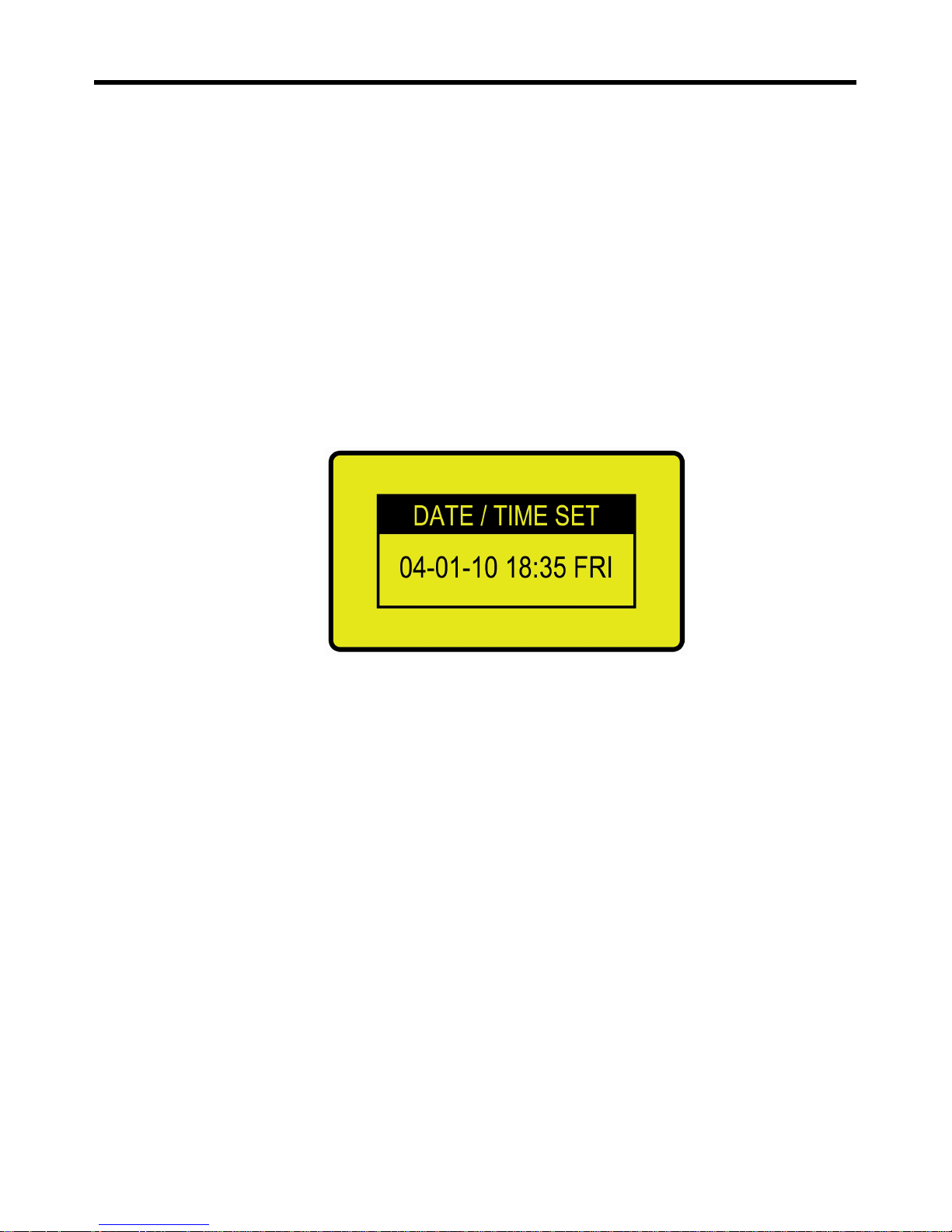
14) SYSTEM DATE/TIME
Date/time is used for a report of system information by trip/state report and schedule operation. Thus,
it is necessary for a trouble or an abnormal condition. Please set date/time.
1) Put menu button once on the main display, see the display to set access code.
2) Put menu button once again, see the display to set the date/time like below
3) Set date/time with controlling up/down and enter button, then put [cancel] button for
returning to main display
4) The day of a week will be set automatically
5) If “:” between hour and minute does not flicker, set all once again.
<Date/time setting screen>
Page 38

UIC-DX270 Series User’s Manual Rev 1.0
- 38 -
5. INSTALLATION PROCESS
1) INSTALLATION PLACE
Please set this product up in the place mentioning below.
⊙ Low temperature change or normal temperature
⊙ No corrosiveness gas
⊙ No low and high humid
⊙ Low machinery vibration
⊙ Low dirt or smoke
⊙ Low effect from an electrical noise
⊙ No effect from a strong magnetic field
2) INSTALLATION PROCESS
⊙ Set up within a slop of fifteen degrees
⊙ Use a steel plate over 2mm as panel
⊙ Do not set up by force
⊙ Fasten the product with an included screw
3) BE WARNING MATTERS ACID CONNECTION WITH LINES
⊙ Please use the shield cable for between control board and sensor to prevent a noise
⊙ Keep input/output Line away over 30cm from Power Line and do not put same lines together
⊙ Set fuse apart to protect the product from overvoltage
⊙ For a high safety, connect parallel Serge Observer to Magnet Coil
⊙ For a high safety, use noise filter
Page 39
UIC-DX270 Series User’s Manual Rev 1.0
- 39 -
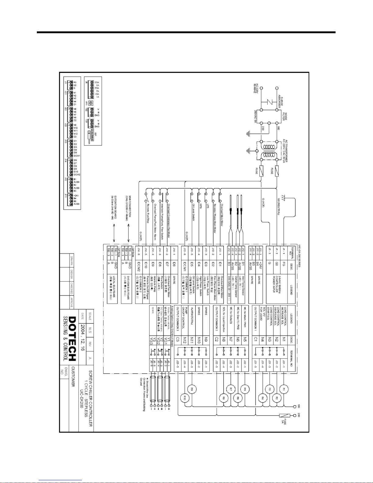
6. ELECTRIC DRAWING
Page 40
UI
C
7
-DX270 Se
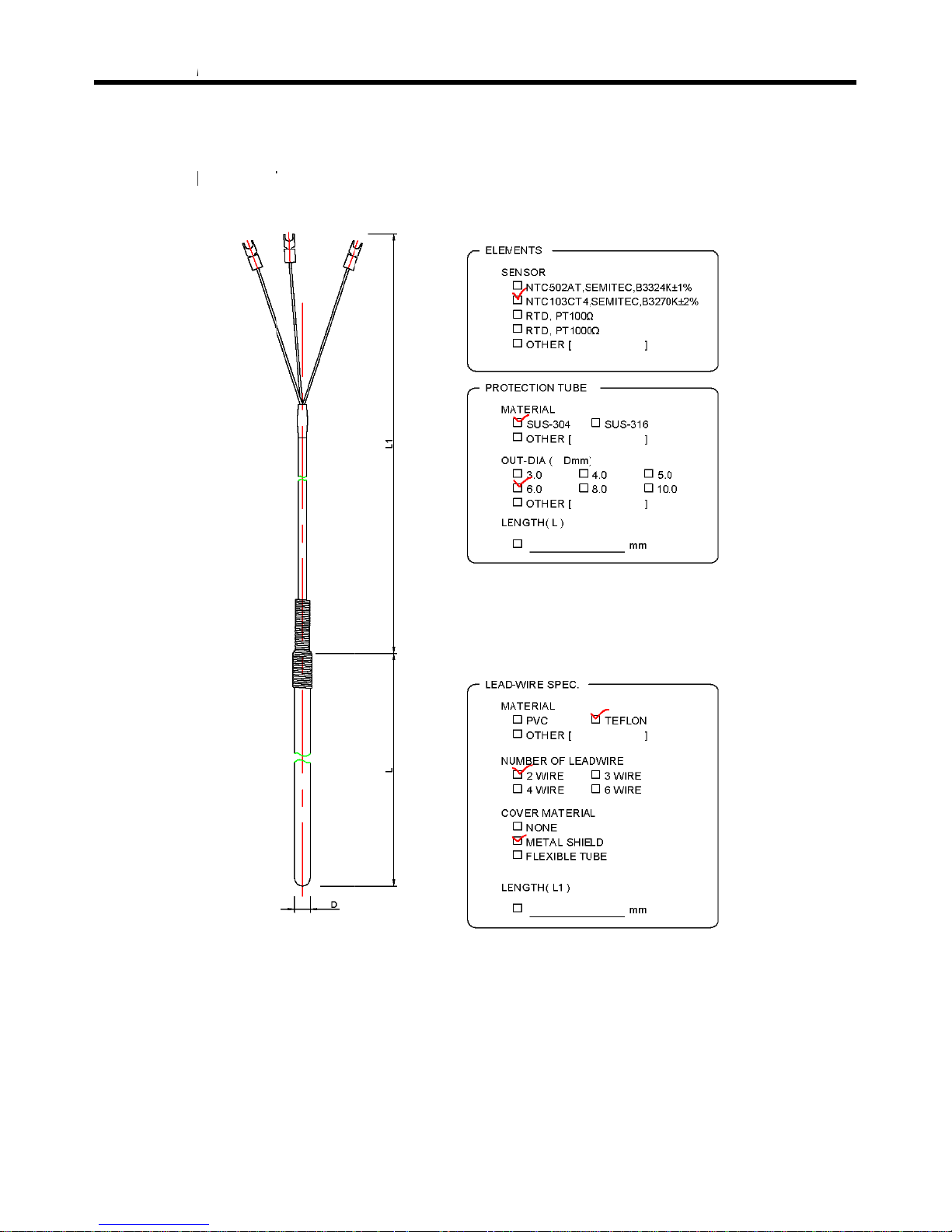
r
. SEN
S
1) TE
M
Discharg
e
Sensor
m
Use tem
p
Sensor t
h
※ The th
r
ies
OR D
A
PERA
T
-gas temp
e
odel: DPR-
T
erature: -5
0
ickness: 6m
ickness and
TA
URE SE
N
rature sens
o
H02-P6D10
~ 250 ℃
m, sensor l
e
the length,
SOR D
A
r only.
0
L
*3m
ngth: 100m
the wire len
- 40 -
TA
m, wire len
g
gth an ord
e
th: 3m
r working drawing are
p
User’s
M
ossible.
anual Rev 1.0
 Loading...