

Page 1
- 1 -
R20150924
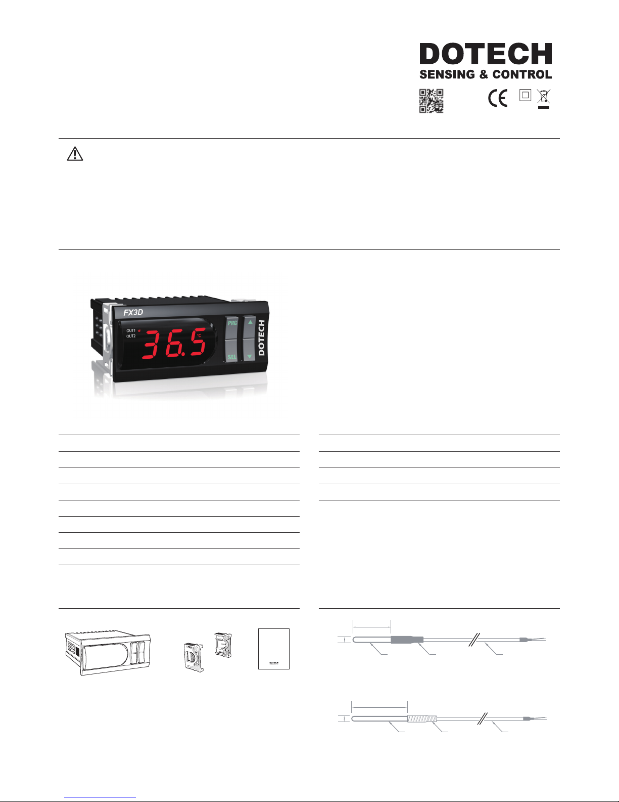
Product Bracket 2ea User's Manual
Technical Specications
Power 100–240Vac, 50/60Hz
Current MAX 6 VA
Connection Screw Bolt Connector(1.5mm2 Wire Use Possibility)
Output Relay Output 2 Point (250Vac / 5A)
Input Temp. Sensor Input 1 Point
Dimensions 78(W)mm X 35(H)mm X 78(D)mm
Operation Temperature: -10 ~ 50°C, Humidity: Below 90%RH
Storage Temperature: -20 ~ 60°C, Humidity: Below 90%RH
Ordering guide
FX3D-00 Basic Model
FX3D-A1 4~20mA Trans output model
FX3D-R4 RS485 Comm. model
FX3D-A1R4 4~20mA Trans output & RS485 Comm. model
※ Specifications are subject to change without prior notice.
Components Accessories
User’s Manual
Ø5
35
SUS PIPE SHRINK TUBE LEAD WIRE
Ø6
100
SUS PIPE SPRING PROTECT LEAD WIRE
DPR-TH01-ET : NTC 5 KΩ at 25 °C / -50~105 °C / ±0.3 °C at 25 °C
DPR-TH02-P6D100L : NTC 10 KΩ at 25 °C / -50~150 °C / ±1.5 °C at 25 °C
Cautions
1. This product may cause an electric shock in handling. Please do not attempt to open it with power turned on.
2. This product should be installed in a place xed secured by a rack or panel.
3.This product can be used under the following environmental condition. ① Indoor ②Pollution Degree 2 ③At an altitude of 2000m or below
4. Power input must be within the designated ranges.
5. To turn on or turn off power supply for this product, please the circuit breaker or switch of a standard product of IEC 60947-1 or IEC 60947-3 product and install it within a close distance allowing convenient operation by user.
6. Please be understood that if this product is dismantled or modied discretionary, after sales service will not be able to be provided.
7. An output wire to be used for this product should be inammable grade FV1 (V-1 grade or above), the thickness of the wire should be AWG No. 20 or above(0.50mm2).
8. In order to prevent it from an inductive noise, please maintain the high-voltage wire and power wire separated.
9. Please avoid installing the product in a place where a strong magnetism, noise, severe vibration and impact exist.
10. When extending the sensor wire, use a shield wire and do not extend it unnecessary long.
11. The sensor wire and signal wire should be away from the power and load wires using conduits separately installed.
12. Please avoid using the product near a device generating strong high frequency noise (high-frequency welding machine, high-frequency sewing machine, high-frequency radiotelegraph, high capacity SCR controller)
13. Product’s damages other than those decribed in the guarantee conditions provided by the manufacturer shall not be respoinsible by us.
14. If this unit is used to control machineries (Medical equipment, vehicle, train, airplane, combustion apparatus, entertainment, processing and transportation equipment, elevator and various safety device etc.) enabling to effect
on human or property, it is required to install fail-safe device.
※
The Aforementioned precautions must be observed, and if you fail to do so, it may cause a product’s breakdown.
※
The specications, dimensions, and etc. are subject to change for enhancement without a prior notice.
Digital Temp Controller
User's Manual
FX3D
- Heating/Cooling Output
- Independent Timer Output
- High/Low Limit Alarm
- Defrost Output
- Sensor Calibration
- Sensor Error Detection
- Automatic Output Cycle after Sensor Error
- Auto Save and Restoration of Parameter Values
- Minimum On/Off Duration Time
- Analog Signal Output(4-20mA)
- Communication via RS485 MODBUS
- Remote Control(FX3D to FX3D)
DOTECH INC. 6F, JOONGANG-ILBO B/D, 30, Dongsan-ro, Danwon-gu, Ansan-si, Gyeonggi-do, KOREA
Page 2
- 2 -
R20150924
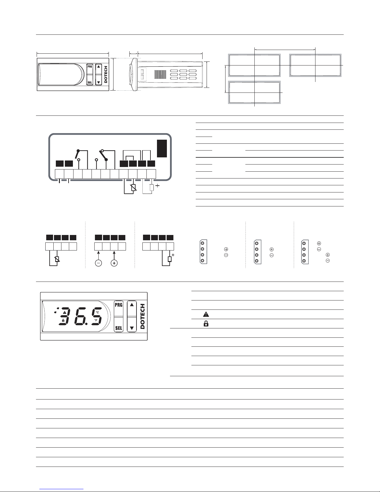
35
78
70
28
8
UNIT : mm
90
40
(Panel Cut-Out : 71mm X 29mm)
FX3D
OUT1
OUT2
Dimensions and Panel Cut-Out Form
Wiring
Constitution
(Function of Display Lamp and Button)
LED
OUT1 Turn on when output #1 is ON (Flickering at standby)
OUT2 Turn on when output #2 is ON (Flickering at standby)
°C / °F
Celsius / Fahrenheit display units
ON at trip, Flickering at alarm
Parameter set up locked
BUTTON
PRG
Use at program setup
SEL
Execute selected menu or Input setup value
▲
Move between menus & Increase setup value
▼
Move between menus & Decrease setup value
PRG
+
▼
If pushing for 10 sec. at the same time ,
setup value is initialized
Code Menu Description / Instructions
Response at
Detection
Reset Type
SYS
Internal Parameter Error In Case of change of set value by an unknown case. Immediate Stop Automatic Reset
OPN
Sensor Open In case of Input sensor open wire(Normal operation after sensor connecting) Immediate Stop Automatic Reset
SHT
Sensor Short In case of Input sensor short circuit Immediate Stop Automatic Reset
LLL
Lower Input Lower sensor input than measuring range Immediate Stop Automatic Reset
HHH
Higher Input Higher sensor input than measuring range Immediate Stop Automatic Reset
ALL
Lower Low Limit Lower Low Limit Alarm than Low Limit Alarm Value Immediate Stop Automatic Reset
ALH
Higher High Limit Higher High Limit Alarm than High Limit Alarm Value Immediate Stop Automatic Reset
Trip / Alarm Messages
※
In case of error occurring, the following messages are ickering at every 0.5 sec. intervals.
L2L1
100-240Vac,
50/60H z
1 2 3 4 5 6 7 8 9 10 11
NTC
OUT1 OUT2
+VDCCOM
FX3D
OPTION
MODULE
c
mA
5A, 250Vac
POWER
SUPPLY
NTC
4~20mA TRANS.
8 9 10 11
NTC +VDCCOM mA
NTC
8 9 10 11
NTC +VDCCOM mA
8 9 10 11
NTC +VDCCOM mA
1
2
3
4
4~20mA
4~20mA
SG
RED
WHITE
BLACK
-A1 Model
4~20mA Output
1
2
3
4
TRX
TRX
SG
RED
WHITE
BLACK
-R4 Model
RS485 COMM.
1
2
3
4
TRX
TRX RED
BLUE
WHIT
E
BLACK4~20mA
4~20mA
-A1R4 Model
4~20mA Output
& RS485 COMM.
8 9 10 11
NTC +VDCCOM mA
8 9 10 11
NTC +VDCCOM mA
8 9 10 11
NTC +VDCCOM mA
Sensor connection Option Module connection
NTC temp. sensor 4~20mA
signal input
4~20mA loop
power sensor
NO Connection Description
1
POWER 100-240Vac, 50/60Hz
2
3
OUT1
Relay output OUT1 when closed
4 Common signal
5
OUT2
Relay output OUT1 when closed
6 Common signal
7 Relay output OUT1 when open
8 COM Common signal
9 NTC Temp. sensor input
10 mA 4~20mA signal input
11 +Vdc 4~20mA sensor power (12Vdc)
Page 3
- 3 -
R20150924
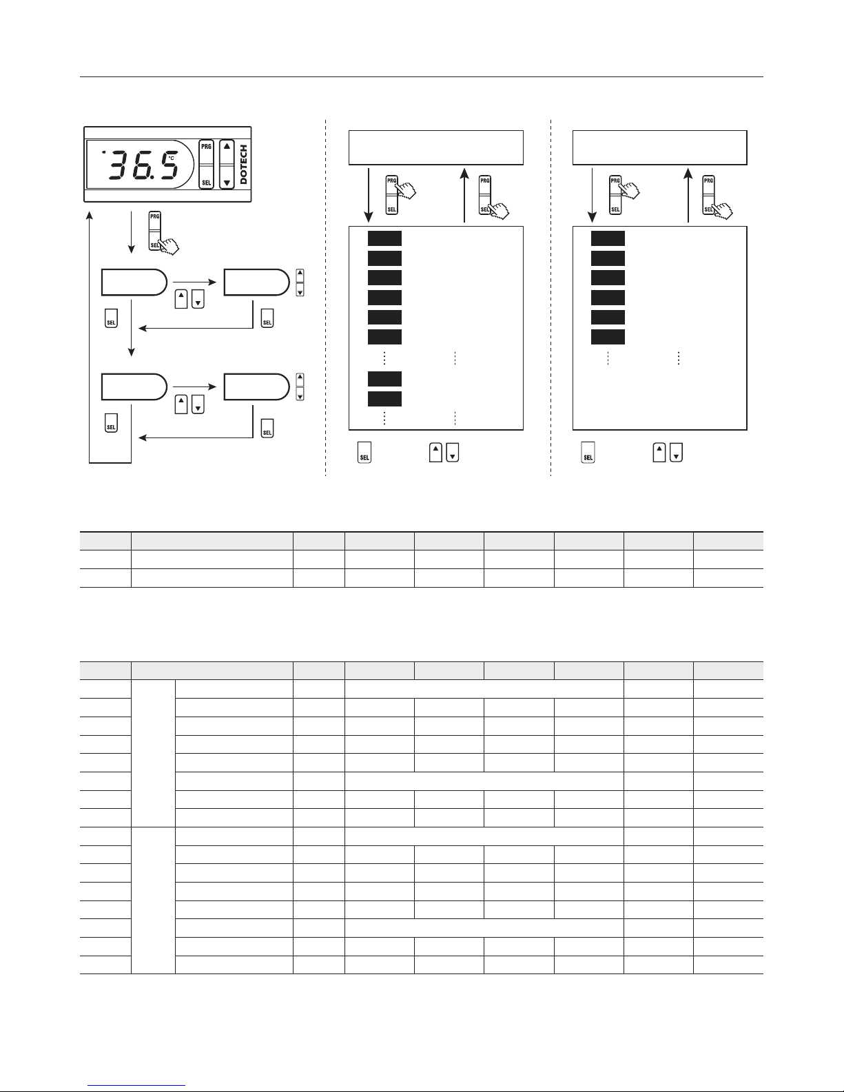
Parameter
Push for 3 sec.
ST 1 0.0
FX3D
OUT1
OUT2
Run Mode
Select Control Type #1
Control Deviation Value #1
ON Delay Time #1
Minimum OFF Time #1
Minimum ON Time #1
Select Deviation Type #1
T Y 1
D F 1
Select Control Type #2
Control Deviation Value #2
T Y 2
D F 2
D T 1
F T 1
N T 1
T P 1
Output #1 setup value
ST 2
0.0
Output #2 setup value
Push
for 5 sec.
Push
for 3 sec.
Menu move Setup value
Run Mode
Select Lock Function
Select Sensor Type
Max. Sensor Input Range
Min. Sensor Input Range
Display Unit
Decimal Point Display
L O C
I N
S H
S L
U N T
D P
Push
for 10 sec.
Push
for 3 sec.
Menu move Setup value
Temperature Setting Group Setting 1 Group Setting 2 Group
※
1) Min OFF Time : It doesn’t make it output within Min. OFF Time after output is OFF. During Min OFF Time, output lamp is turned on with output after it ickers every 1 second intervals.
※
2) Min ON Time : It is for avoiding frequent ON/OFF of control output and maintains ON condition in spite of OFF condition during Min ON Time after being turned on.
※
3) Select Deviation Type : It selects deviation type. e.g) Condition (Cooling, Setup value 10.0, Deviation 1.0)
In case of +deviation -> Operate at ON (11.0) / OFF (10.0) In case of ±deviation -> Operate at ON (10.5) / OFF (9.5)
Temperature Setting Group
(SEL Button Push for 3 Sec.)
No Menu Code Unit Step Min Max Default Custom Setup
4 0001 Output #1 setup value
ST1
°C 0.1
UL1 UH1
0.0
4 0002
Output #2 setup value
ST2
°C 0.1
UL2 UH2
0.0
Setting 1 Group
(PRG Button Push for 5 Sec.)
No Menu Code Unit Step Min Max Default Custom Setup
4 0003
Output
#1
Select Control Type
TY1 OFF
(0) : Display C (1) : Cooling mode H (2) : Heating mode
C
(1)
4 0004
Control Deviation Value
DF1
°C
0.1
0.1 999.9
1. 0
4 0005 ON Delay T ime
DT1
Sec 1 0 999
1
4 0006 Minimum OFF Time(※1)
FT1
Sec 1 0 999
0
4 0007 Minimum ON Time(※2)
NT1
Sec 1 0 999
5
4 0008 Deviation Type(※3)
TP1 P
(0) : Deviation PN (1): ± Deviation
P
4 0009 Set Value Max.
UH1
°C 1
UL1 SH 10 0
4 0 010 Set Value Min.
UL1
°C 1
SL UH1 -45
4 0 011
Output
#2
Select Control Type
TY2 OFF
(0) : Display C (1) : Cooling mode H (2) : Heating mode
C
(1)
4 0 012 Control Deviation Value
DF2
°C 0.1 0.1 999.9
1. 0
4 0 013 ON Delay Time
DT2
Sec 1 0 999
2
4 0 014 Minimum OFF Time(※1)
FT2
Sec 1 0 999
0
4 0 015 Minimum ON Time(※2)
NT2
Sec 1 0 999
5
4 0 016 Deviation Type(※3)
TP2 P
(0) : Deviation PN (1): ± Deviation
P
4 0 017 Set Value Max.
UH2
°C 1
UL2 SH 10 0
4 0 018 Set Value Min.
UL2
°C 1
SL UH2 -45
Page 4
- 4 -
R20150924
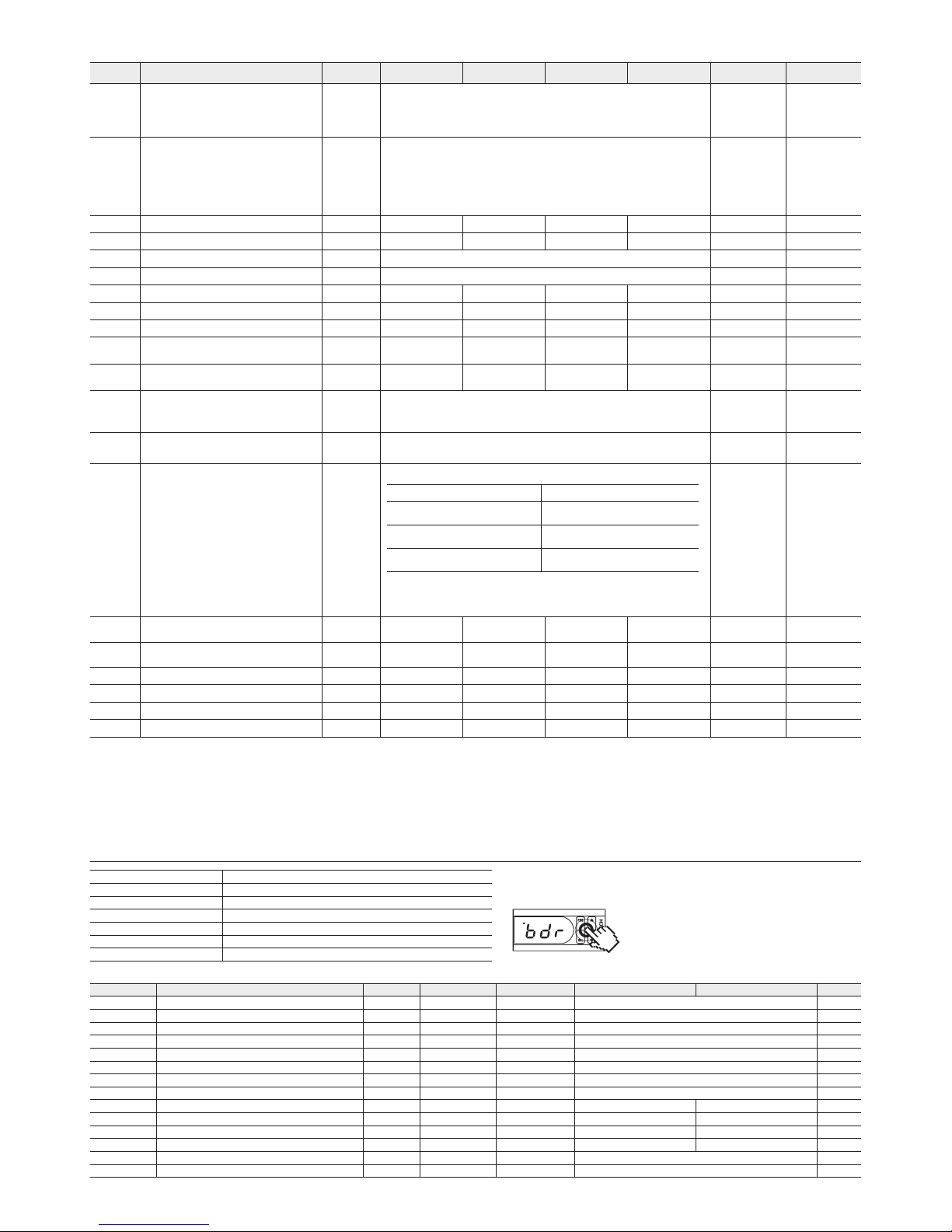
Setting 2 Group
(PRG Button Push for 10 Sec.)
No Menu Code Unit Step Min Max Default Custom Setup
4 0061 Lock Function
LOC
OFF
(0) : Lock cancel
LC
1 (1) : Setting 2 group lock
LC2
(2) : Setting 1,2 group lock
LC3
(3) : Setting 1, 2 group, temp. setup lock
OFF
(0)
4 0062 Sensor Type
IN
TH 1
(0) : DPR-TH01 (-50~105°C)
TH2
(1) : DPR-TH02 (-50~150°C)
420
(2) : 4-20mA signal input
(In case of connecting with press.&humidity sensor)
ST 1
(3) : OUT1 set temperature (
ST1
) display
ST2
(4) : OUT1 set temperature (
ST2
) display
STD
(5) :
ST 1
or
ST2
(※1)
TH 1
(0)
4 0063 Max. Sensor Input Range
SH
°C 1
SL 999 10 5
4 0064 Min. Sensor Input Range
SL
°C 1
-199 SH -50
4 0065 Unit of temperature
UNT oC
(0) : Celsius oF (1) : Fahrenheit
oC
(0)
4 0066 Decimal Point Display(※2)
DP 0. 1
(0) : Decimal point display 1(1) : Do not display decimals
0. 1
(0)
4 0067 Sensor Correction(※3)
COR
°C 0.1
-19.9 19.9 0.0
4 0068 Sensor Input Filter
SFT
Sec 0.1
0.1 5.0 2.0
4 0069 Sensor Value Display Cycle
SDT
Sec 0.1
0 5.0 0.5
4 0070
Operation Cycle Output at Error
Occurrence #1(※4)
CL1
Min 1
0 999 OFF
(0)
4 0071
Operation Ratio Output at Error
Occurrence #1(※4)
DU1
% 1
0 10 0 50
4 0072
Analogue Trans.
Output(4~20mA) Mode
(-A1 model)
AOM
PV
(0) : Current Temp. H (1) : Heating proportional control
C (2) : Cooling proportional control
ST 1
(3) : Set value Temp.#1
ST2
(4) : Set value Temp.#2
PV
(0)
4 0073 Setup Value Unication Mode (※5)
STO
OFF
(0) : Output #1, #2 separation mode
0N
(1) : Unication mode
OFF
(0)
4 0074
Output #2, Select Extended
Function.
(Display
TY2
as
OFF
)
N2
OFF
(0) : Control output operate as the function set at
TY2
T1M
(7) : Timer output
(Regular cycle timer output)
DFH
(8) : Timer output
(Regular cycle timer output : heater defrost)
DFG
(9) : Timer output
(Regular cycle timer output : hot gas defrost)
OFF
(0)
4 0075
Output #2, Timer OFF Time
(Defrost Cycle)
OF2
Min 1
0 999 360
4 0076
Output #2, Timer ON Time
(Defrost Time)
ON2
Min 1
0 999 30
4 0077 Alarm Range High Limit (※7)
ALH
- 0.1
ALL SH 30.0
4 0078 Alarm Range Low Limit (※7)
ALL
- 0.1
SL ALH - 10
4 0079 Alarm Sensing Hysteresis
AHY
K 0.1
0 99.9 1. 0
4 0080 Communication Address (※8)
ADR
- 1
-64 64 1
Automatic reset alarm Manual reset alarm(※6)
AL1
(1):
Output ON at sensor alarm +
high limit alarm
AL4
(4):
Output ON & manual reset at
sensor alarm + high limit alarm
AL2
(2):
Output ON at sensor alarm +
low limit alarm
AL5
(5):
Output ON & manual reset at
sensor alarm + low limit alarm
AL3
(3):
Output ON at sensor alarm +
high/low limit alarm
AL6
(6):
Output ON & manual reset at
sensor alarm + high/low limit alarm
(※1)
STD
: Sensor Value Display Value : Display set value of output 1,2 as present value by input ON/OFF.
(※2) Decimal Point Display : Decimal point display : It sets the current value display unit as 0.1/1. i.e. In case of setting as ‘1’, it displays the current value with cutting the decimal place.
(※3) Correct Temp. Sensor : Correct deviations of temperature sensor. e.g) if displayed temperature is 19°C and actual temperature is 18°C, it is corrected by inputting -1.0°C
(※4) Control Output Operation at Error Occurrence : When error occurs, control output repeatedly operates OFF/ON until error is reset.
e.g) In case of setting of operation cycle : 60minutes, ON ratio 20%, it repeatedly operates a cycle of OFF (48 minutes) / ON (12 minutes).
(※5) Setup Value Unication Mode : In case of setting this function as ON, setup value is unied and controlled as 1 case.
(※6) Manual Reset alarm : In case of selecting manual reset alarm, it is reset by re-inputting power or pushing PRG button rapidly 2 times.
(※7) In case of occurrence of high or low limit alarm, it doesn’t aect control output #1 at all.
(※8) Communication Address : Master mode address is to -1 from -64.
Communication Table
No Menu Unit Type Size (Word) FX MMI Scale
4 0101 Product status codes Digital INT 16 Refer to bit status below
Bit 0 Output 1 ON / OFF status Digital Bit 0 : OFF 1 : ON
Bit 1 Output 2 ON / OFF status Digital Bit 0 : OFF 1 : ON
Bit 8 Defrost output ON / OFF status Digital Bit 0 : OFF 1 : ON
Bit 12 Min. range alarm Digital Bit 0 : Normal 1 : Alarm
Bit 13
Max. range alarm
Digital Bit 0 : Normal 1 : Alarm
Bit 14 Sensor (disconnection, short-circuit) Alarm Digital Bit 0 : Normal 1 : Alarm
Bit 15 EEPROM alarm Digital Bit 0 : Normal 1 : Alarm
4 0102 Current temperature value (PV) °C Analog INT 16 -50 ~ 105 -500 ~ 1050 1/10
4 0103 FND display current temp. value (PV) °C Analog INT 16 -50 ~ 105 -500 ~ 1050 1/10
4 0104 Output 1 (
ST1
) settings (*read only) °C Analog INT 16 -50 ~ 105 -50 0 ~ 1050 1/10
4 0105 Output 2 (
ST2
) settings (*read only) °C Analog INT 16 -50 ~ 105 -50 0 ~ 1050 1/10
4 0107
Command of compulsory defrost with manual
Analog INT 16 1 : START (Auto-reset)
4 0108
Command of compulsory defrost termination
Analog INT 16 1 : STOP (Auto-reset)
Change of BPS
Default value of this model is 4800bps and it should be changed separately.
1. Entry into parameter relating to BPS
Press
PRG
+
SEL
+ ▲ + ▼ buttons simultaneously
for 5 seconds as shown in the figure
2.
BDR
BDR Commun ication Speed (Press the SEL button eight times)
Adjust BPS using ▲ / ▼ buttons from the
BDR
parameter
(48 : 4800bps, 96 : 9600bps,
19 2
: 19200bps,
384
: 38400bps)
3. Store set value (Press the SEL button for three seconds)
Transmission line connection Multiple line
Communications method RS485 (2-wire, half-duplex)
BPS BPS default 4800 BPS
Parity, Data, Stop bit None, 8 Data, 1 Stop
Protocol Type Modbus RTU Mode
Function Code Read HOLD REGISTERS (0x03) / Preset Single Register (0x06)
Poll interval 100msec
Communication
FX3D
OUT1
OUT2
 Loading...