

Page 1
-1-
DPX300 R20151015
Digital Pressure Switch
CAUTIONS
1. This product may cause an electric shock in handling. Please do not attempt to open it with power turned on.
2. This product should be installed in a place fixed secured by a rack or panel.
3.This product can be used under the following environmental condition.
① Indoor ②Pollution Degree 2 ③At an altitude of 2000m or below
4. Power input must be within the designated ranges.
5. To turn on or turn off power supply for this product, please the circuit breaker or switch of a standard product of IEC
60947-1 or IEC 60947-3 product and install it within a close distance allowing convenient operation by user.
6. Please be understood that if this product is dismantled or modified discr etionary, after sales service will not
be able to be provided.
7. An output wire to be used for this product should be inflammable grade FV 1 (V-1 grade or above), the thickness
of the wire should be AWG No. 20 or above(0.50mm
2
).
8. In order to prevent it from an inductive noise, please maintain the high-voltage wire a nd power wire separated.
9. Please avoid installing the product in a place where a strong magnetism, noise, severe vibrat ion and impact exist.
10. When extending the sensor wire, use a shield wire and do not extend it unnecessary long.
11. The sensor wire and signal wire should be away from the power and load wires using conduits separately installed.
12. Please avoid using the product near a device generating strong high frequency noise (high-fr equency welding machine,
high-frequency sewing machine, high-frequency radiotelegraph, high capacity SCR controller)
13. Product’s damages other than those decribed in the guarantee conditions provided by the manufacturer s hall not be
respoinsible by us.
14. If this unit is used to control machineries (Medical equipment, vehicle, train, airplane, combustion apparatus,
entertainment, processing and transportation equipment, elevator and various safety device etc.) enabling to effect
on human or property, it is required to install fail-safe device.
※ The Aforementioned precautions must be observed, and if you fail to do so, it may cause a product’s breakdown
.
※ The specifications, dimensions, and etc. are subject to change for enhancement without a prior notice.
DPX300
User Manual
DOTECH INC.
6F, JOONGANG-ILBO B/D, 30, Dongsan-ro, Danwon-gu,
Ansan-si, Gyeonggi-do, KOREA
TEL: +82-31-495-3767 FAX: +82-31-495-3917
www.dotech21.com
1. OVERVIEW
※ FEATURES
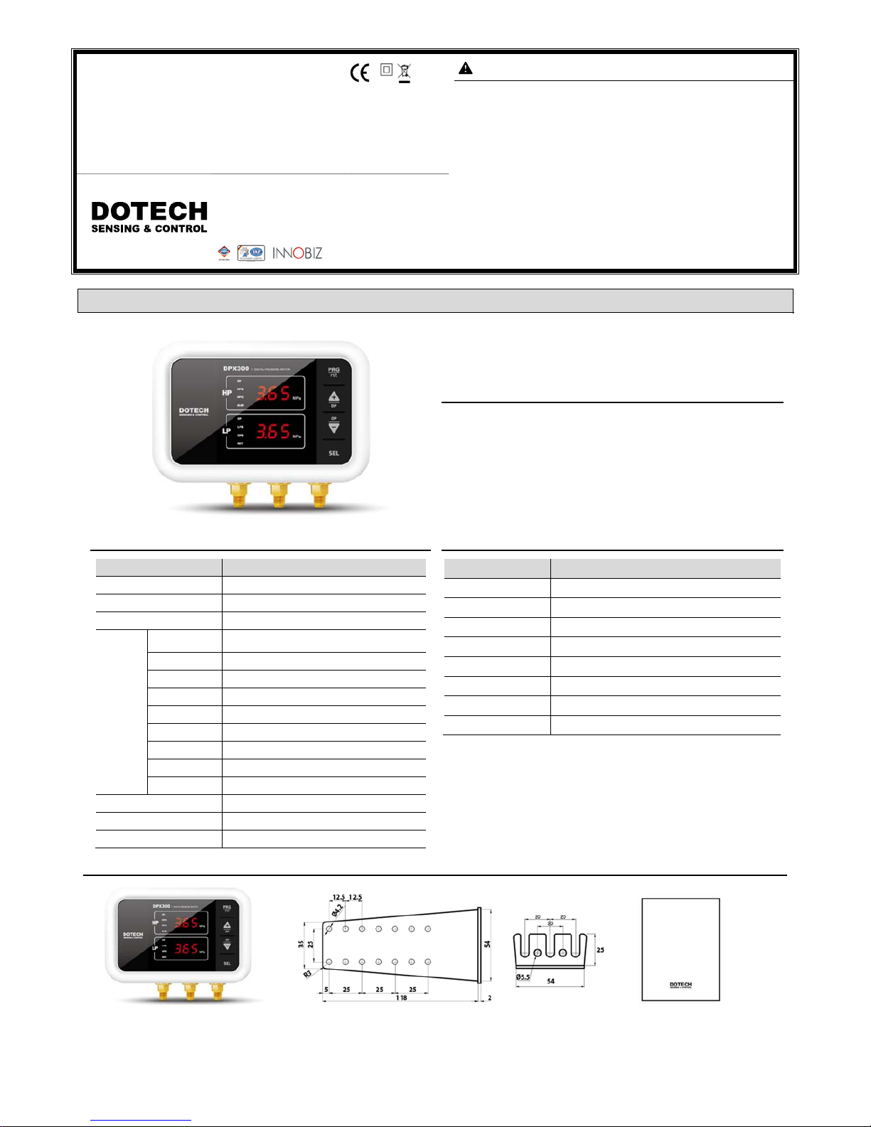
- High pressure protection, Low pressure protection, Oil pressure protection,
an integrated high pressure fan control
- Automatic / Manual reset, Selection of various refrigerants
- Precise pressure control, Sensor offset, Sensor error detection
: SPECIFICATIONS(STANDARD MODEL)
Description
Power 100 – 240 Vac, 50/60 Hz
Power Consumption MAX 10 VA
Output 4P Relay Outputs / 250Vac, 30Vd c, 5 A
Pressure
Sensors
Measurement
Range
-0.10 ~ 5.00 MPa
Accuracy ±1.0 %FS
Overpressure 150 %FS
Stability ±0.5 %FS/year
Shock 20 g sinusoidal, 11 msec
Vibration x-y-z directions of 5 -20 00Hz / 10g
Working Temp. -40 ~ 120 °C
Connection 7/16UNF” / MALE
Pressure Type Gauge
Dimensions 159(W)mm X 128(H)mm X 58(D)mm
Operation Temperature -10~50 °C / Humidity 90%RH or less
Storage Temperature -20~60 °C / Humidity 90%RH or less
: SELECTION GUIDE
Model Description
DPX300-HLO-00-MPA Digital Pressure Switch Standard(Pressure Unit: MPa )
DPX300-HLO-R4-MPA Digital Pressure Switch for Communication(RS485 Modb us )
DPX300-HLO-00-KGF Digital Pressure Switch Standard(Pressure Unit: kgf/cm2)
DPX300-HLO-R4-KGF Digital Pressure Switch for Communication(RS48 5 Modbus )
DPX300-HLO-00-BAR Digital Pressure Switch Standard(Pressure Unit: bar )
DPX300-HLO-R4-BAR Digit al Pressure Switch for Communication(RS485 Modb us )
DPX300-HLO-00-PSI Digital Pressure Switch Standard(Pressure Unit: psi )
DPX300-HLO-R4-PSI Digit al Pressure Switch for Communication(RS485 Modbus )
※ Communication is not supported in standard models.
※ Specify the pressure unit when ordering.
: Supplied Contents
Bracket 1ea User Manual
※ This item is provided for securing the brack et tightening all bolts please.
Page 2
-2-
DPX300R2015101
5
2. INSTALLATION
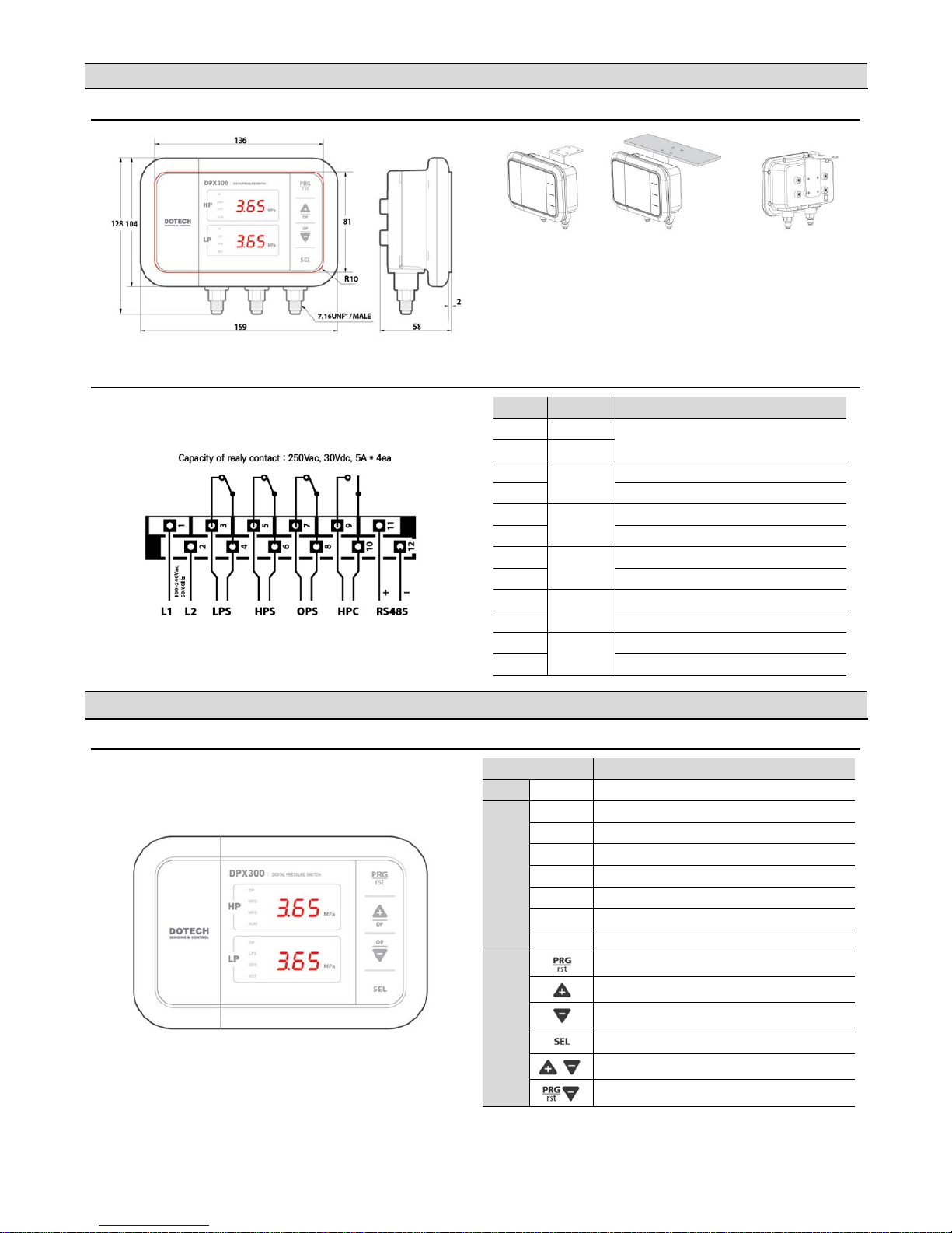
:DIMENSIONS AND MOUNTING(unit: mm)
※ Please install a siphon tube to protect from pulsating pressure and high temperature contact.
LP : Low Pressure | OP : Oil Pressure | HP : High Pressure
(unit : mm)
: WIRING DIAGRAM
No Connection Description
1 L1
100–240Vac, 50/60Hz Power Input
2 L2
3
LPS
Open when the low pressure is below lower limit
4
Common signal
5
HPS
Open when the high pressure is above the upper limit
6
Common signal
7
OPS
Open when the oil pressure is below lower limit
8
Common signal
9
HPC
Closed when the high pressure is above the upper limit
10
Common signal
11
RS485
TRX + signal
12
TRX – signal
3. USER INTERFACES
: DISPLAY AND CONTROLS
Description
DP
On when displaying differential pressure
LED
HPS
ON/OFF of Output / ON when Overpressure
HPC
ON/OFF of Output / ON when Fan is Running
ALM
On when alarm occurs
OP
On when displaying oil pressure
LPS
ON/OFF of Output / ON when Underpressure
OPS
On/Off of output / On when oil pressure
RST
ON when Manual Reset
Button
Parameter Settings / Manual Reset(if pressed twice quickly)
Increase or Move Up
Decrease or Move Down
Select & Save / Display of Saturated Temperature
Display differential pressure value, oil pressure value
S
etup values will be initialized if pushing PRG button
and ▼button for 10 seconds.
Page 3
-3-
DPX300R2015101
5
4. PARAMETER
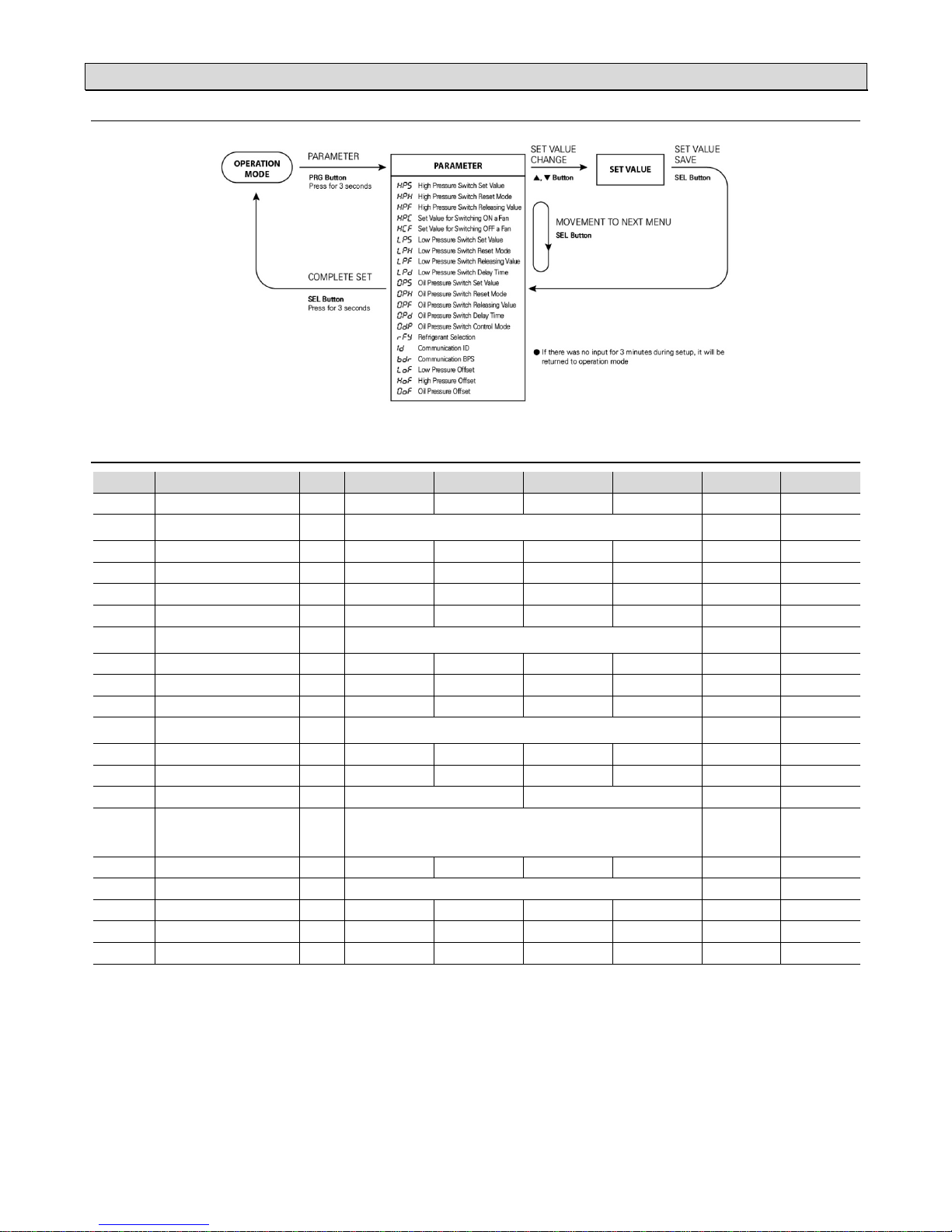
: PARAMETER CHANGE
.
: PARAMETER TABLE
No Menu Code Unit Step Min Max Default CustomSetup
4 0031
High Pressure Switch Set Value
HPS MPa 0.01
-0.1 0 5.00
2.60
4 0032
High Pressure Switch Reset Mode (※1)
(Manual / Automatic Reset)
HPH A (0)= Automatic Reset H (1)= Manual Reset H (1)
4 0033
High Pressure Switch Releasing Value
HPF MPa 0.01
-0.1 0 HPS- 0.01
2.50
4 0041
Set Value for Switching ON a Fan
HPC MPa 0.01
-0.1 0 5.00
1.50
4 0043
Set Value for Switching OFF a Fan
HCF MPa 0.01
-0.1 0 HPC- 0.01
1.40
4 0051
Low Pressure Switch Set Value
LPS MPa 0.01
-0.10 5.00
0.25
4 0052
Low Pressure Switch Reset Mode (※1)
(Manual / Automatic Reset)
LPH A (0)= Automatic Reset H (1)= Manual Reset A (0)
4 0053
Low Pressure Switch Releasing Value
LPF MPa 0.01
LPS+ 0.01 5.00
0.35
4 0055
Low Pressure Switch Delay Time (※2)
LPD sec 1
0 999
0
4 0065
Oil Pressure Switch Set Value (※3)
0PS MPa 0.01
-0.00 5.00
0.10
4 0066
Oil Pressure Switch Reset Mode (※1)
(Manual / Automatic Reset)
0PH A (0)= Automatic Reset H (1)= Manual Reset A (0)
4 0067
Oil Pressure Switch Releasing Value (※3)
0PF MPa 0.01
OPS + 0.01 5.10
0.20
4 0068
Oil Pressure Switch Delay Time (※4)
0PD sec 1
0 999
0
4 0069
Oil Pressure Switch Control Mode (※5)
0DP 0-L (0)=OP - LP H-0(1)= HP - OP 0-L(0)
4 0061
Refrigerant Selection (※6)
RFY
R22 (0)= R22
R23 (1)= R23
123 (2)= R-123
124 (3)= R-124
134 (4)= R-134a
404 (5)= R-404a
407 (6)= R-407c
410 (7)= R-410a
507 (8)= R-507
R22 (0)
4 0063
Communication ID
ID - 1
1 255 1
4 0064
Communication BPS
BDR
48 (0)= 4800 96 (1)= 9600 192 (2)= 19200 384 (3)= 38400
96 (1)
4 0071
Low Pressur e Offse t (※7)
LOF MPa 0.01
-1.99 1.99 0.00
4 0072
High Pressure Offset (※7)
HOF MPa 0.01
-1.99 1.99 0.00
4 0073
Oil Pressure Offset (※7)
0OF MPa 0.01
-1.99 1.99 0.00
(※1) Reset mode:
Automatic Reset (A ): It will be reset automatically when reaching releasing pressure value.
Manual reset (H ): It will not be reset when reaching release pressure value unless users press RST button twice consecutively.
(※2) Low pressure switch delay time :
If output is activated, it maintenances ON status during minimum ON time even under the OFF condition.
(※3) Oil Pressure Switch Set Value :
Differential pressure = Oil pressure –Low pressur
e
It becomes an ON condition for output if differential pressure valve (DP) is less than oil switch pressure switch set value (OPS). Output is de-activated if
differential pressure value (DP) is higher than oil pressure switch releasing value (OPF) after output is activated.
(※4) Oil Pressure Switch Delay Time :
Output will be activated after maintaining delay time which is set even though it is under the ON condition.
LED lamp will be turned on a light simultaneously with output after flickering during delay time.
(※5)
Oil Pressure Switch Control Mode
Control mode for oil pressure switch: In case of using control mode for oil pressure switch as 0-L (OP – LP),
it can be come to a output state of OPS due to pressure equalizing at the status of compressor stop.
(※6) Refrigerant selection :
Display saturation temperature in accordance with selected refrigerant.
(※7) Offset :
Offset the differential fo r pressure sensor.
e.g) If displayed pressure value: 0.20MPa and actual pressure value: 0.22MPa It is offset by inputting +0.02MPa.
Page 4
-4-
DPX300R2015101
5
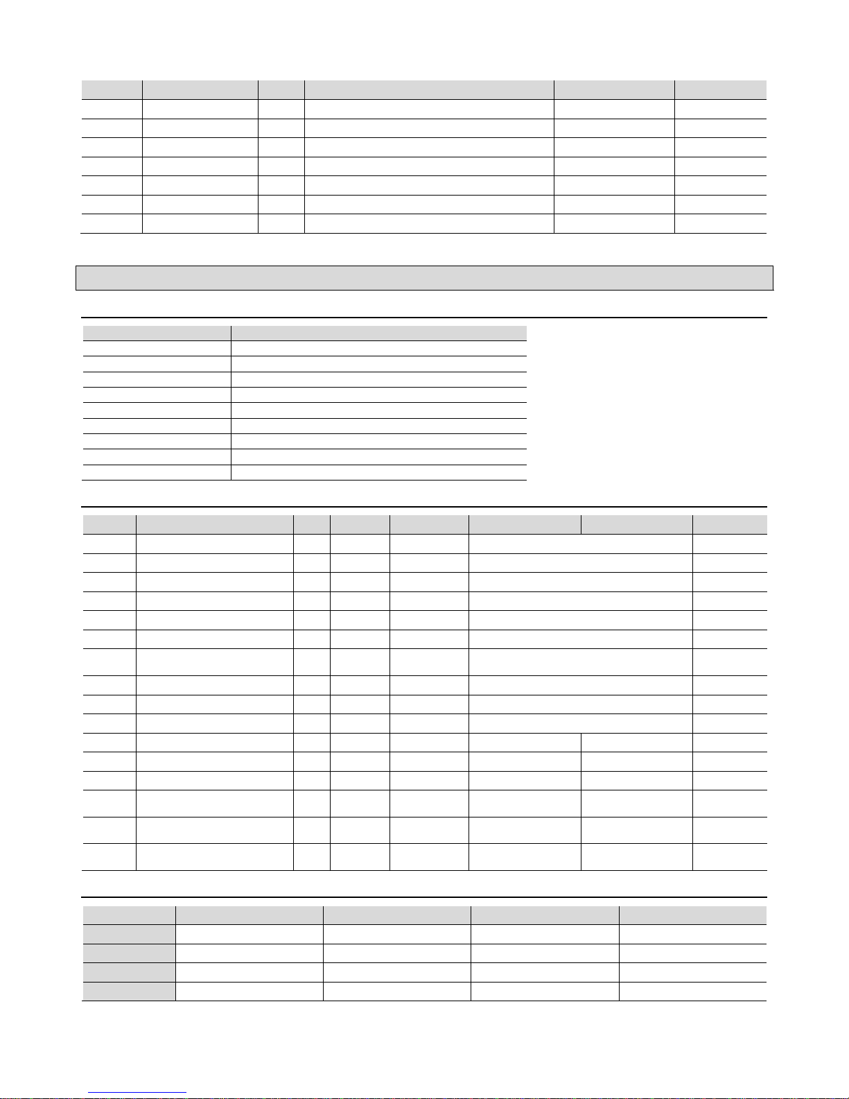
: TRIP / ALARM MESSAGES
No Menu Code Descri ption / Instructions Response at Detection Reset Type
1
Internal Paramete r Error
5 Y 5
Change any parameters and turn off. Then restart. Immediate Stop Automatic Reset
2
High Pressure Sensor Open
HO P
Please check a high pressure sensor because it is open. Immediate Stop Automatic Reset
3
High Pressure Sensor Short
H5 H
Please check a high pressure sensor because it is short. Immediate Stop Automatic Reset
4
Low Pressure Sensor Open
LO P
Please check a low pressure sensor because it is open. Immediate Stop Automatic Reset
5
Low Pressure Sensor Short
L5 H
Please check a low pressure sensor because it is short. Immediate Stop Automatic Reset
6
Oil Pressure Sensor Open
0O P
Please check a oil pressure sensor because it is open. Immediate Stop Automatic Reset
7
Oil Pressure Sensor Short
05 H
Please check a oil press ure sensor because it is shor t. Immed iate Stop Automatic Reset
※ When it alarms, it beeps and all the outputs are cut off. To stop the beep, press the reset.
5. COMMUNICATIONS SPECIFICATIONS
: Communication Model ( -R4 )
Description
Transmission line connection Multiple line
Communications method RS485 (2-wire, half-duplex)
BPS BPS default 9600 BPS
Parity, Data, Stop bit None, 8 Data, 1 Stop
Protocol Type Modbus RTU MODE
Function Code Read HOLD REGISTERS (0x03) , Preset Single Register (0x06)
Maximum Read Word 16 Word
Media Type BELDEN 9841 / 9842, LG LIREV-AMESB
Poll interval 100msec
: HOLD REGISTERS
※ Pressure Unit Conversion Table
MPa bar kgf/cm psi
1MPa
1
1ⅹ10
1.0197162ⅹ10 1.450382ⅹ10
1bar 1ⅹ10 1 1.019716 1.4503824ⅹ10
1kgf/cm 9.80665ⅹ10 9.80665ⅹ10 1 1.4223393ⅹ10
1psi 6.895ⅹ10 6.8947ⅹ10 7.0307ⅹ10 1
Address Menu Unit Type Size (Word) DPX200 MMI Scale
4 0011 Output status code - Digital INT 16 Refer to bit status below -
Bit0 High Pressure Switch Set Value - Digital Bit 0 : OFF 1 : ON -
Bit1 Set Value for Switching ON a Fan - Digital Bit 0 : OFF 1 : ON -
Bit2 Low Pressure Switch Set Value Digital Bit 0 : OFF 1 : ON -
Bit3 Oil Pressure Switch Set Value Digital Bit 0 : OFF 1 : ON -
4 0013 Alarm status code - Digital INT 16 Refer to bit status below -
Bit0
Internal con trol variables error
(Internal control factor error)
- Digital Bit 0 : Normal 1 : Alarm -
Bit1 High pressure sensor faulty - Digital Bit 0 : Normal 1 : Alarm -
Bit2 Low pressure sensor faulty Digital Bit 0 : Normal 1 : Alarm -
Bit3 Oil pressure sensor faulty Digital Bit 0 : Normal 1 : Alarm -
4 0023 Display of high pressure value MPa Analog INT 16 -0.10 ~ 5.00 -10 ~ 500 1/100
4 0024 Display of low pressure value MPa Analog IN T 16 -0.10 ~ 5.00 -10 ~ 500 1/100
4 0025 Display of oil pressure value MPa Analog INT 16 0.00 ~ 5.00 0 ~ 500 1/100
4 0026
Display of saturation temperature for
low pressure
°C Analog INT 16 -150.0 ~ 200.0 -1500 ~ 2000 1/10
4 0027
Display of saturation temperature for
high pressure
°C Analog INT 16 -150.0 ~ 200.0 -1500 ~ 2000 1/10
4 0030
Display of differential pressure value
(Oil pressure – Low pressure)
°C Analog INT 16 0.0 ~ 5.10 0 ~ 510 1/100
 Loading...