

Page 1
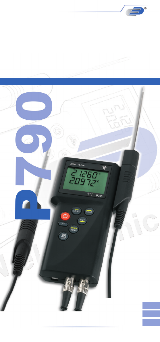
P790
Präzisions-2-Kanal-Handmessgerät
Precision 2-channel hand-held
measuring instrument
Instrument de mesure portatif de haute
précision à double canal
Bedienungsanleitung 3
Operating Instruction 12
Mode d‘emploi 21
www.dostmann-electronic.de
Page 2
7.
6.
5.
4.
3.
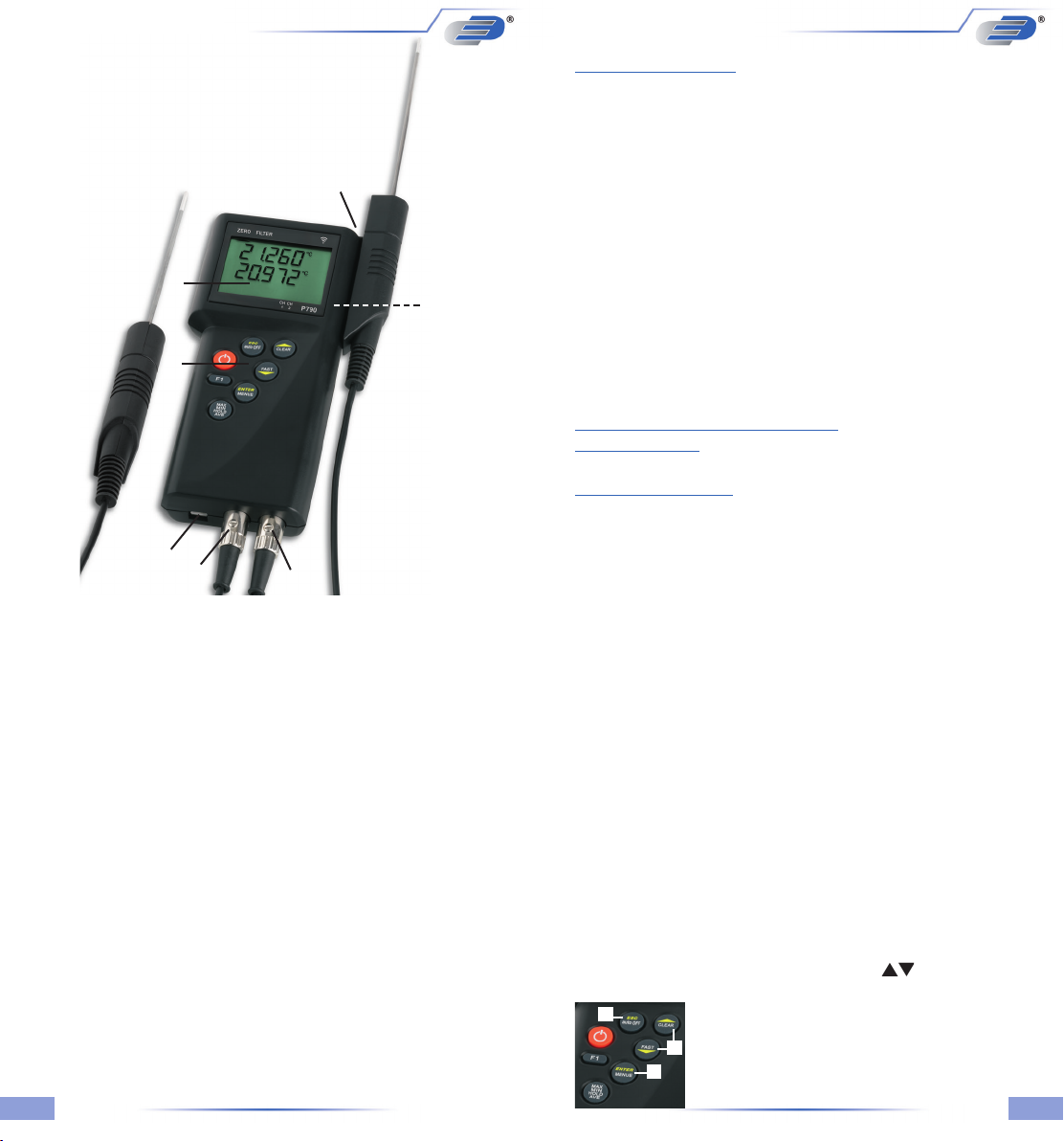
1. Fühlerhalterung
2. Aufstellbarer Bügel für Stand- und Hängefunktion
3. 1. Anschlußport für Fühlersensoren
4. 2. Anschlußport für Fühlersensoren
5. USB Anschlußport für PC
6. Tastatur
7. Großes LC-Display
1. Mounting device for probe handle
2. Retractable stand
3. Measuring port 1
4. Measuring port 2
5. USB PC interface port
6. Keyboard
7. Big LC-Display
1. Support de sonde
2. Support de xation pour poser ou
suspendre l’instrument
3. 1. Port de raccordement pour
capteurs sondes
4. 2. Port de raccordement pour
capteurs sondes
5. Port de raccordement USB pour PC
6. Clavier
7. Grand écran LCD
Inhaltsverzeichnis
1. Handhabung/ Einleitung 3
1.1. Hinweise 3
1.2. Inbetriebnahme 3
1.3. Ein-/Ausschalten 3
1.4. Menüstruktur 3
1.
1.4.1 Einheiten-Umschaltung (Unit) 4
1.4.2 Automatische Fühlererkennung (Smartprobes) 4
1.4.3 Fühler auswählen / (Prob) 4
1.4.4 Differenztemperatur (L in2) 5
1.4.5 Kalibriermodus (CAL) 5
1.4.6 Kanalaktivierung (Chnl) 8
2.
1.4.7 Speicherbedienung (Lo6) 8
1.4.8 Bluetooth (bLE) 9
1.5. Speicherabfrage (HOLD/MAX/MIN/AVG) 9
1.6. Messzyklus ändern (FAST-Taste) 9
1.7. AUTO-OFF-Funktion 10
1.8. TARA-Funktion (ZERO-Taste F1) 10
2. Spannungsversorgung / Batteriewechsel 10
3. Fehlermeldungen 11
...............................................................................................................................
1. Handhabung/ Einleitung
- Zum Reinigen des Instrumentes keine aggressiven Reinigungsmittel
verwenden, sondern nur mit einem trockenen oder feuchten Tuch abreiben.
- Messgerät an einem trockenen und sauberen Ort aufbewahren.
- Vermeiden Sie Gewalteinwirkung wie Stöße oder Druck.
- Stecker nicht mit Gewalt in die Buchsen einstecken. Die Messkanal- und
Schnittstellenstecker sind unterschiedlich.
- Sollte beim Einschalten kein Sensor am Messgerät angeschlossen sein,
so zeigt das Display „open“. (Bitte Kapitel Fehlermeldung nachschlagen).
1.2 Inbetriebnahme
Vor dem Einschalten den/die Messfühler in die dafür vorgesehene Buchse des
Messinstrumentes anstecken und sicherstellen das eine volle 9V-Blockbatterie
eingelegt ist (Im Lieferumfang sind 2 Batterien enthalten). Die Fühleranschlussbuchsen sind entsprechend am Gerätegehäuse mit 1 (Kanal 1), 2 (Kanal 2) und
USB gekennzeichnet.
1.3 Ein-/Ausschalten
Durch Betätigen der ON/OFF-Taste wird das Messgerät ein- und ausgeschaltet.
Nach dem Einschalten werden auf dem Display für ca. 1,5 Sekunden alle Segmente angezeigt (Vollsegmentanzeige). Anschließend wechselt das Instrument
automatisch in den Messmodus und zeigt den aktuellen Messwert an. In der
oberen Displayzeile wird der Messwert für Kanal 1, darunter der Messwert für
Kanal 2 angezeigt.
1.4 Menüstruktur
Geräteeinstellungen wie Messgrößen, Fühlerkalibrierungen, Kanäle deaktivieren
usw. erfolgen über ein Menübaum. In das Hauptmenü gelangen Sie über die
Taste (ENTER/MENUE). Mit Hilfe der Pfeiltasten ( ) können Sie die
gewünschten Menüpunkte auswählen. Durch Betätigen der ESC-Taste
gelangen Sie zurück in den Messmodus.
1.
1. Taste (ESC)
2. Pfeiltasten
3. Taste (ENTER/MENUE)
2.
3.
32
Page 3
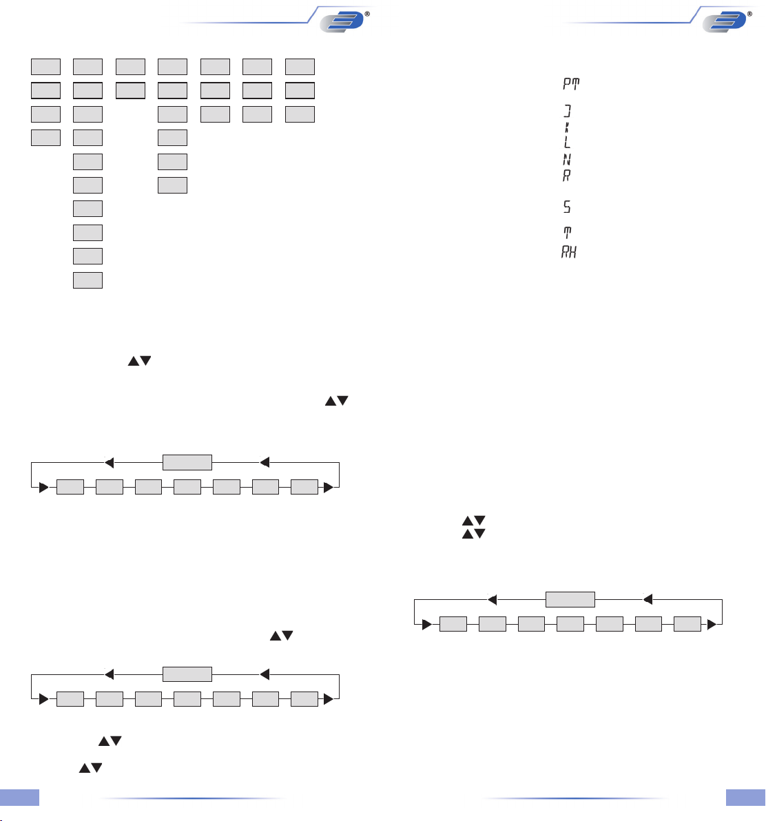
Menübaum
Unit
Prob
°C
L in 2
PT
T1-T2
°F
0
J
K
L
N
CAL
CoFF
oP 1
oP 2
oP 3
oP 4
ChnI
oFF
on
Lo6
oFF
on
bLE
oFF
on
R
S
T
RH
1.4.1 Einheiten-Umschaltung °C, °F und Ohm (Unit)
Unit = Einheit
Messeinheit Temperatur (°C=Celsius, °F=Fahrenheit, o=Ohm)
Drücken Sie die Taste (ENTER/MENUE) und wählen Sie Unit mit
Hilfe der Pfeiltasten ( ) aus, danach drücken Sie (ENTER/MENUE)
erneut. Es erscheint je nach eingestelltem Fühler (siehe Kapitel 1.4.2 +1.4.3 Prob)
entweder °C/°F auf der rechten Displayseite. Das Zeichen o (für Ohm) wird
zum Auswählen unten rechts im Display dargestellt. Mit den Pfeiltasten ( )
wählen Sie die gewünschte Einheit aus und bestätigen diese mit (ENTER/
MENUE). Mit (ESC) gelangen Sie danach wieder in den Messmodus.
MENUE
Unit Prob L in 2 CAL ChnI Lo6 bLE
1.4.2 Automatische Fühlererkennung (Smartprobes)
Smartfühler mit Eprom erkennt das Messgerät automatisch. Eine Auswahl
der Fühler im Menü Prob ist nicht erforderlich! Das Gerät zeigt option CAL 4
(1 Messfühler mit Eprom) oder CAL 44 (2 Messfühler mit Eprom) nach dem
Einschalten an.
1.4.3 Fühler auswählen / (Prob)
Bei Verwendung von Fühlern der Messgeräte (P700-P770) bitte die Fühler
gemäß nachfolgender Beschreibung auswählen. Drücken Sie die Taste (ENTER/
MENUE) und wählen Sie Prob mit Hilfe der Pfeiltasten ( ) aus, danach
drücken Sie (ENTER/MENUE) erneut.
MENUE
Messgröße Fühlerauswahl LCD-Anzeige geeignet für
(Probe) Messgerätetypen:
...............................................................................................................................
Temperatur Pt100 (RTD) P700/P705/P750/P755/
P770/P755-LOG/P770-LOG
...............................................................................................................................
Temperatur Fe-CuNi Typ J für alle P700-Messgeräte
...............................................................................................................................
Temperatur NiCr-Ni Typ K für alle P700-Messgeräte
...............................................................................................................................
Temperatur Fe-CuNi Typ L für alle P700-Messgeräte
...............................................................................................................................
Temperatur NiCrSi-NiSi Typ N für alle P700-Messgeräte
...............................................................................................................................
Temperatur Pt13Rh-Pt Typ R P700/P705/P750/P755/
P770/P755-LOG/P770-LOG
...............................................................................................................................
Temperatur Pt10Rh-Pt Typ S P700/P705/P750/P755/
P770/P755-LOG/P770-LOG
...............................................................................................................................
Temperatur Cu-CuNi Typ T für alle P700-Messgeräte
...............................................................................................................................
Feuchte %rF P700/P705/P750/P755/
P770/P755-LOG/P770-LOG
...............................................................................................................................
Mit (ENTER/MENUE) bestätigen Sie die gewünschte Einstellung. Mit (ESC)
gelangen Sie danach wieder in den Messmodus.
Wichtig!
Hinweis: Stellen Sie sicher das die richtige Messgröße für den angeschlossenen
Fühler eingestellt ist. Wird eine Messgröße im Menü Prob verändert und mit der
Entertaste bestätigt wird automatisch die Standardkalibrierung verwendet.
Wichtig!
Hinweis zum Kombinationsfühler (Temperatur und Feuchte):
Stellen Sie als Messgröße relative Feuchte für den Messkanal ein an dem
der Kombifühler angeschlossen ist. Möchten Sie den Temperaturwert des
angeschlossenen Kombifühlers ebenfalls angezeigt bekommen müssen Sie den
Kanal deaktivieren an dem kein Kombifühler angeschlossen ist (Siehe Kapitel
1.4.6 / Chnl).
1.4.4 Anzeigeoption Differenztemperatur
aktivieren/deaktivieren / (L in2)
Drücken Sie die Taste (ENTER/MENUE) und wählen Sie L in2 mit Hilfe der
Pfeiltasten ( ) aus, danach drücken Sie (ENTER/MENUE) erneut. Mit den
Pfeiltasten ( ) können Sie jetzt die Anzeige Differenztemperatur aktivieren
T1-T2 oder deaktivieren (T1-T2 auf dem LCD sichtbar = Differenztemperatur
aktiv). Mit (ENTER/MENUE) bestätigen Sie die gewünschte Einstellung.
Mit (ESC) gelangen Sie danach wieder in den Messmodus.
MENUE
Unit Prob L in 2 CAL ChnI Lo6 bLE
Hinweis: Zur Anzeige der Differenztemperatur müssen beide Kanäle aktiviert
sein.
Unit Prob L in 2 CAL ChnI Lo6 bLE
Auf der linken Displayseite erscheint eine kleine 1, die den Kanal anzeigt. Mit
den Pfeiltasten ( ) können Sie den Kanal ändern für den ein Fühler ausgewählt werden soll. Mit (ENTER/MENUE) bestätigen Sie die Auswahl. Mit den
Pfeiltasten ( ) können Sie jetzt folgende Fühler auswählen:
1.4.5 Kalibrierfunktion / (CAL)
Ihr Messgerät bietet Ihnen die Möglichkeit beim Tausch von Fühlern eine
einfache Kalibrierung durchzuführen, um so die herstellungsbedingten
Toleranzen der Fühler auszugleichen und eine gleichbleibend hohe Genauigkeit
Ihrer Messkette zu gewährleisten.
54
Page 4
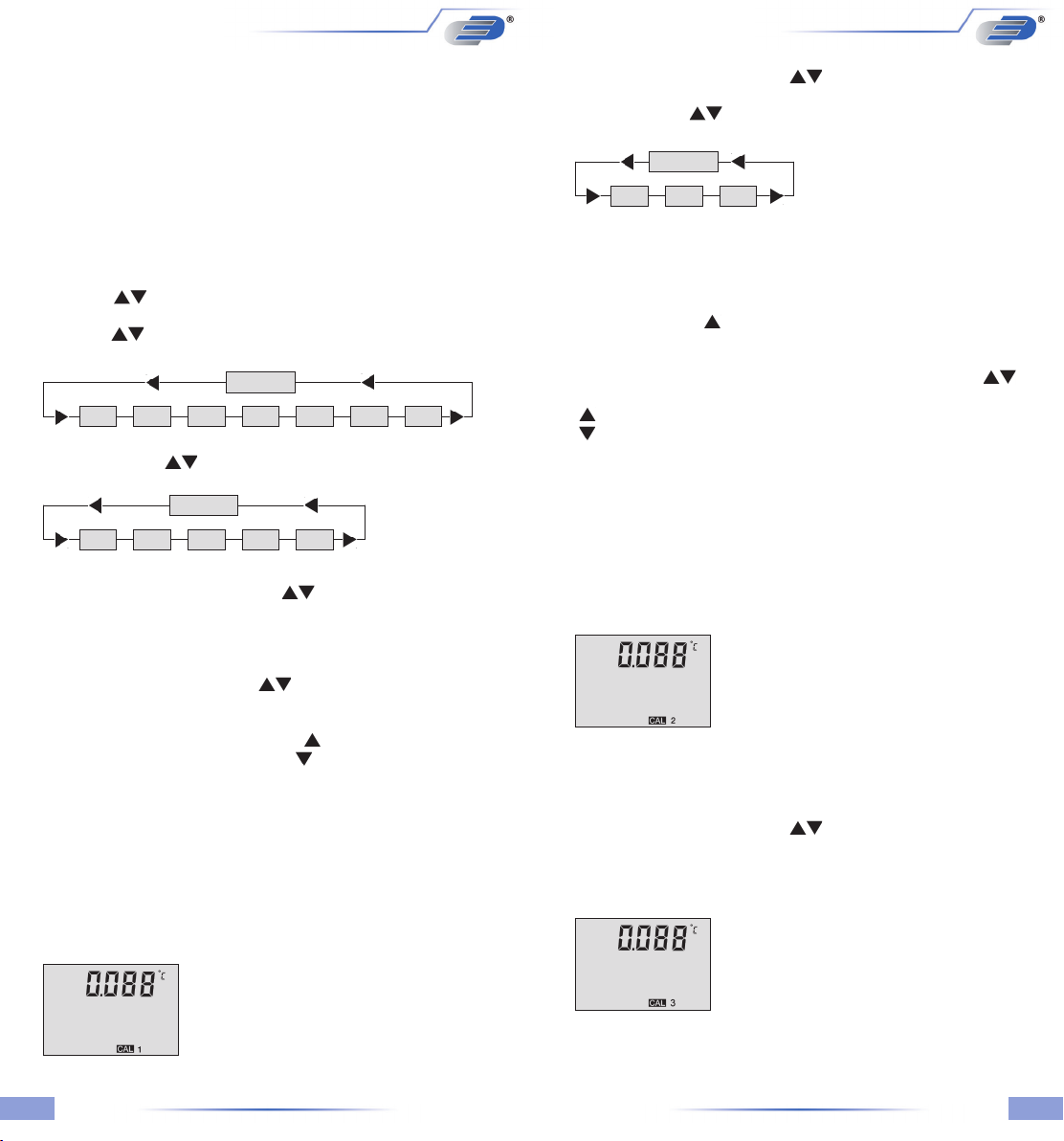
Das Gerät beinhaltet 5 verschiedene Kalibriermodi:
1) (CoFF): Standardkennlinie
(z.B. bei Pt100-Widerstandsmessungen EN60751)
2) (oP 1): Nummernkalibrierung (Der 2 x 4-stellige Code ist bei unseren
Fühlern auf dem Handgriff gut sichtbar angebracht)
entspricht einem 2-Punkteabgleich
3) (oP 2): Physikalische Kalibrierung (Kalibrierung mit Vergleichsnormalen:
1-Punkt-, 2-Punkt- oder 3-Punkteabgleich möglich)
4) (oP 3): Kalibrierung Koefzienten nach EN60751 (RO, ABC)
5) (oP 4): EEprom-Fühler mit Kalibrierung (automatische Erkennung)
CAL = kalibrieren
Drücken Sie die Taste (ENTER/MENUE) und wählen Sie CAL mit Hilfe der
Pfeiltasten ( ) aus, danach drücken Sie (ENTER/MENUE) erneut. Auf
der linken Displayseite erscheint eine kleine 1, die den Kanal anzeigt. Mit den
Pfeiltasten ( ) können Sie den Kanal auswählen (1 oder 2) der kalibriert
werden soll. Mit (ENTER/MENUE) bestätigen Sie die Auswahl.
MENUE
Unit Prob L in 2 CAL ChnI Lo6 bLE
Mit den Pfeiltasten ( ) können Sie jetzt die gewünschte Kalibrierfunktion
auswählen.
CAL
CoFF oP 1 oP 2 oP 3 oP 4
1) DIN-Kalibrierung DIN EN 60751 / (CoFF)
Wählen Sie mit Hilfe der Pfeiltasten ( ) (CoFF) aus. Mit (ENTER/
MENUE) bestätigen Sie die gewünschte Einstellung. Mit (ESC) gelangen Sie
danach wieder in den Messmodus.
2) Nummernkalibrierung / oP1
Wählen Sie mit Hilfe der Pfeiltasten ( ) oP 1 aus. Mit (ENTER/ MENUE)
bestätigen Sie die gewünschte Einstellung. Im unteren Displayteil erscheint
eine kleine 1. Dahinter stehen 4 Zeichen (Hex-Code / 0 .. F). Die 4 Zeichen
können Sie durch die Pfeiltaste nach oben ( ) ändern. Zur nächsten Ziffer
springen Sie mit der Pfeiltaste nach unten ( ). Sind alle 4 Zeichen wunschgemäß eingegeben betätigen Sie zur Bestätigung (ENTER/MENUE). Es
erscheint eine kleine 2 und Sie können die 4 nachfolgenden Zeichen ebenso
ändern. Mit (ESC) gelangen Sie danach wieder in den Messmodus.
Wichtig:
Bei Aufruf von oP 1 durch (ENTER/MENUE) ist die Funktion oP 1 (Nummern-
kalibrierung) aktiviert, selbst wenn das Menü anschließend durch (ESC) verlassen
wird.
Beispiel der Messwertanzeige nach Eingabe einer Fühlerkalibriernummer:
Die kleine 1 unten rechts in Verbindung mit dem
Anzeigesegment CAL zeigt Ihnen an, dass die
Nummernkalibrierung oP 1 aktiviert wurde.
3) Physikalische Kalibrierung / oP 2
Wählen Sie mit Hilfe der Pfeiltasten ( ) oP 2 aus. Mit (ENTER/MENUE)
bestätigen Sie die gewünschte Einstellung. Im unteren Displayteil erscheint 1 P.
Mit den Pfeiltasten ( ) können Sie zwischen einer 1-Punkt (1 P), 2-Punkt
(2 P) und 3-Punkt (3 P)-Kalibrierung auswählen.
oP 2
1 P 2 P 3 P
Beispiel einer 1-Punktkalibrierung:
Bestätigen Sie 1-Punktkalibrierung 1 P mit (ENTER/MENUE). Auf dem Display
erscheint CALC. Sobald der Messwert stabil steht bestätigen Sie mit (ENTER/
MENUE). In der ersten Displayzeile wird der zuletzt angezeigte Messwerte
eingefroren, in der 2. Displayzeile wird als Vorgabewert -100.000 dargestellt.
Mit der CLEAR-Taste ( ) verschieben Sie die den Kommapunkt und wählen
somit die gewünschte Anzahl an Nachkommastellen aus. Mit (ENTER/MENUE)
bestätigen Sie die gewünschte Einstellung.
Auf dem Display blinkt jetzt das Vorzeichen „-“. Mit den Pfeiltasten ( )
ändern Sie das Vorzeichen, sowie die Ziffern:
) Ändern das blinkende Segment (Ziffer oder Vorzeichen)
(
( ) Springt zum nächsten Segment (Ziffer oder Vorzeichen)
(An dieser Stelle geben Sie die Referenztemperatur ein.)
Mit (ENTER/MENUE) bestätigen Sie die gewünschte Einstellung. Sie benden
sich jetzt wieder im Messmodus.
Wichtig:
Ein Abbruch der physikalischen Kalibrierung oP 2 kann mit der ESC-Taste
durchgeführt werden.
Beispiel der Messwertanzeige nach einer physikalischen Kalibrierung gegen ein
Vergleichsnormal:
Die kleine 2 unten rechts in Verbindung mit dem
Anzeigesegment CAL zeigt Ihnen an dass die
Nummernkalibrierung oP 2 aktiviert wurde.
4) Kalibrierung nach Callendar van Dusen / oP 3
Option 3 dient zur Aktivierung von Kalibrierkoefzienten nach dem Callendar
van Dusen (RO,ABC). Die Kalibrierkoefzienten müssen vorher via PC an das
Messgerät übertragen werden. Dafür wird die Software P7 _CALC benötigt.
Wählen Sie mit Hilfe der Pfeiltasten ( ) oP 3 aus. Mit (ENTER/ MENUE)
bestätigen Sie die gewünschte Einstellung.
Beispiel der Messwertanzeige nach einer physikalischen Kalibrierung gegen ein
Vergleichsnormal:
Die kleine 3 unten rechts in Verbindung mit dem
Anzeigesegment CAL zeigt Ihnen an dass die
Nummernkalibrierung oP 3 aktiviert wurde.
76
Page 5
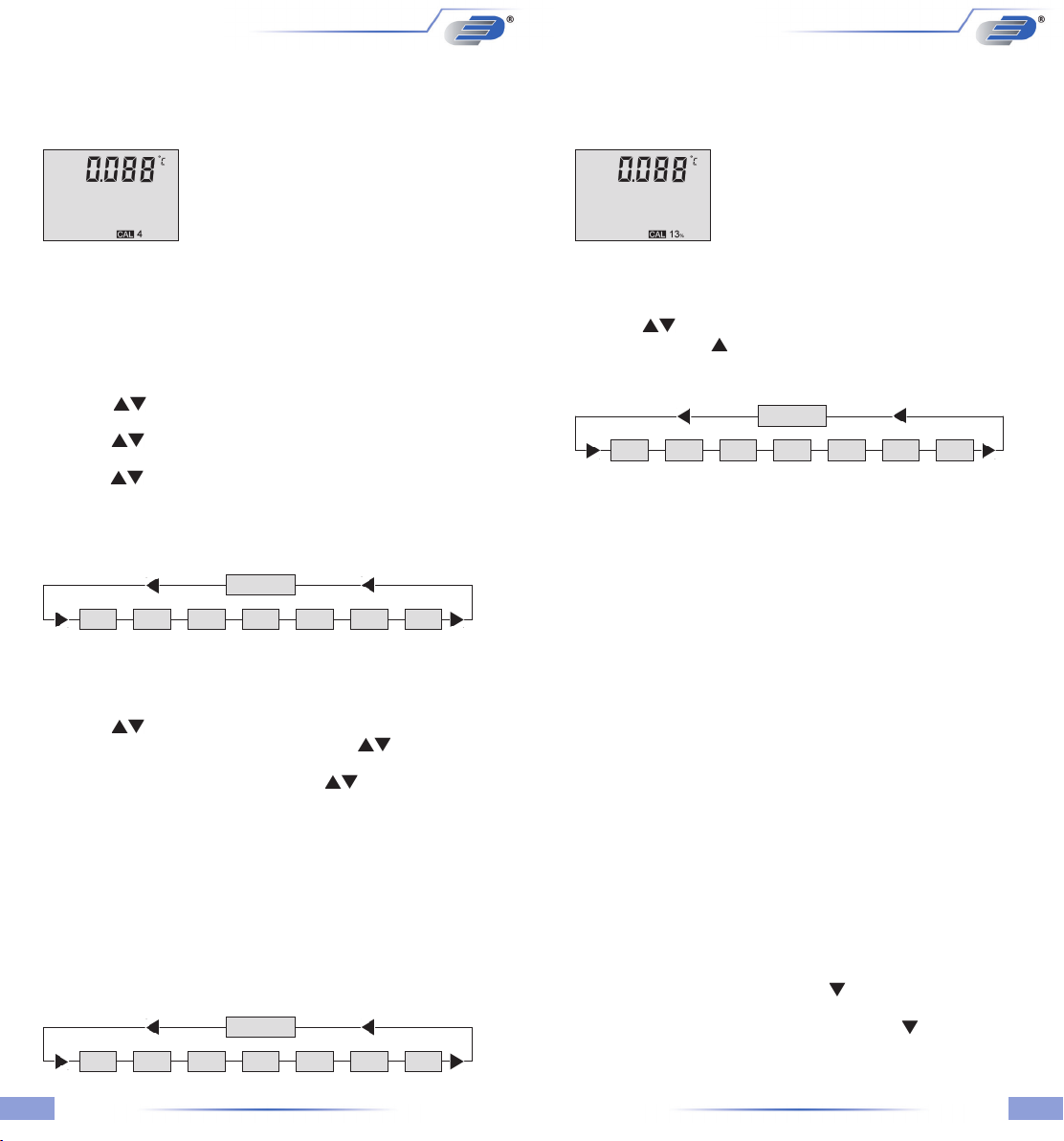
5) EEprom-Fühler mit Kalibrierung (automatische Erkennung) / oP 4
Die Option 4 wird automatisch aktiviert wenn beim Einschalten des Messgerätes
ein Fühler mit integriertem EEprom angesteckt ist.
Beispiel der Messwertanzeige nach einer physikalischen Kalibrierung gegen ein
Vergleichsnormal:
Die kleine 4 unten rechts in Verbindung mit dem
Anzeigesegment CAL zeigt Ihnen an dass die
Nummernkalibrierung oP 4 aktiviert wurde.
Bei Auswahl der manuellen Speicherung können Sie durch betätigen der
ESC-Taste zu jedem gewünschten Zeitpunkt die Messwerte abspeichern.
Mit (ENTER/MENUE) bestätigen Sie die Eingabe. Mit (ESC) gelangen Sie
danach wieder in den Messmodus.
Beispiel der Messwertanzeige im Aufzeichnungsmode (Logger aktiviert):
Unten rechts wird prozentual der belegte Speicher
blinkend angezeigt (0-99%). Bei aktivierter Kalibrier option wechselt die Anzeige zwischen Kalibrieroption
und Prozentanzeige.
Wichtig:
Sobald ein EEprom-Fühler bei eingeschaltetem Instrument abgezogen wird, ruft
das Gerät automatisch das CAL-Menü auf.
1.4.6 Messkanäle aktivieren/deaktivieren / (Chnl)
Chnl = Channel = wählen
Drücken Sie die Taste (ENTER/MENUE) und wählen Sie Chnl mit Hilfe der
Pfeiltasten ( ) aus, danach drücken Sie (ENTER/MENUE) erneut. Auf
der linken Displayseite erscheint eine kleine 1, die den Kanal anzeigt. Mit den
Pfeiltasten ( ) können Sie den Kanal auswählen der aktiviert oder deaktiviert werden soll. Mit (ENTER/MENUE) bestätigen Sie die Auswahl. Mit den
Pfeiltasten (
) können Sie jetzt den eingestellten Kanal aktivieren on oder
deaktivieren off. Mit (ENTER/MENUE) bestätigen Sie die gewünschte Einstellung.
Mit (ESC) gelangen Sie danach wieder in den Messmodus.
Wichtig: Es bleibt immer mindestens ein Kanal aktiv!
MENUE
Unit Prob L in 2 CAL ChnI Lo6 bLE
1.4.7 Speicherverwaltung Lo6
Drücken Sie die Taste (ENTER/MENUE) und wählen Sie Lo6 mit Hilfe der
Pfeiltasten ( ) aus, danach drücken Sie (ENTER/MENUE) erneut. In der
unteren Displayzeile erscheint (on). Mit den Pfeiltasten ( ) können Sie jetzt
den Loggermodus starten (on) oder stoppen (off). Mit (ENTER/MENUE) bestätigen
Sie die Auswahl. Wiederum mit den Pfeiltasten ( ) wählen Sie zwischen
automatischen (Auto) oder manuellen (SPot) Speichern und bestätigen mit
(ENTER/MENUE). Über die Auswahl (Add) und (nLo6) entscheiden Sie
zwischen Hinzufügen oder Erstellen einer neuen Aufzeichnungsdatei. Bei
Auswahl der automatischen Speicherung werden Sie am Ende aufgefordert den
Messintervall auszuwählen:
1 S 1 Sekunde
5 S 5 Sekunde
10 S 10 Sekunde
20 S 20 Sekunde
30 S 30 Sekunde
1 M 1 Minute
2 M 2 Minute
5 M 5 Minute
10 M 10 Minute
20 M 20 Minute
MENUE
Unit Prob L in 2 CAL ChnI Lo6 bLE
1.4.8 Bluetooth aktivieren/deaktivieren / (bLE)
bLE = Bluetooth = off / on
Drücken Sie die Taste (ENTER/MENUE) und wählen Sie bLE mit Hilfe der
Pfeiltasten ( ) aus, danach drücken Sie (ENTER/MENUE) erneut. Mit der
Pfeiltaste nach oben ( ) können Sie jetzt Bluetooth aktivieren on oder
deaktivieren off. Mit (ENTER/MENUE) bestätigen Sie die gewünschte Einstellung.
Mit (ESC) gelangen Sie danach wieder in den Messmodus.
MENUE
Unit Prob L in 2 CAL ChnI Lo6 bLE
1.5 Speicherabfrage (HOLD MAX MIN AVE)
Nach erstmaligem Betätigen der (HOLD MAX MIN AVE) Taste werden die zum
Zeitpunkt der Betätigung aktuellen Messwerte als Hold-Wert im Display eingefroren bzw. angezeigt. Durch wiederholtes Drücken können die gespeicherten
Maximum-, Minimum und Durchschnittswerte abgefragt werden.
Hinweis:
Während der Speicherabfrage werden die Extrema (MAX MIN) und der Mittelwert (AVE) nicht weitergeführt oder berechnet.
Speicher löschen (MAX MIN AVE)
Nur im Messmodus möglich: (CLEAR) Taste einmal betätigen. Auf dem
Display erscheint Clr. – Es werden jetzt alle bis zu diesem Zeitpunkt gemessenen
Extrema (MAX MIN und AVE) gelöscht.
1.6 Messzyklus ändern FAST-Taste
(Normal-Mode / FAST-Mode / Filter-Mode)
Das Messgerät verfügt über 3 unterschiedliche Messgeschwindigkeiten:
Normal-Mode: höchste Auösung
(0,001 im Bereich -199,999 bis +199,999)
FAST-Mode: reduzierte Auösung
(0,01 im Bereich -199,99 bis +199,99)
Filter-Mode: höchste Auösung
(0,001 im Bereich -199,999 bis +199,999)
Im Filter-Mode wird der angezeigte Messwert durch Mittelung mehrerer
Messwerte stabilisiert. Nachdem Einschalten bendet sich das Gerät im
Normal-Mode. Drücken Sie die Taste (FAST /
) einmal. Sie benden sich jetzt
im Fast-Modus. Die Messwerteauösung (Anzahl Kommastellen) ist jetzt um
eine Stelle reduziert. Drücken Sie erneut die Taste (FAST / ) und Sie benden
sich im Filter-Mode.
98
Page 6
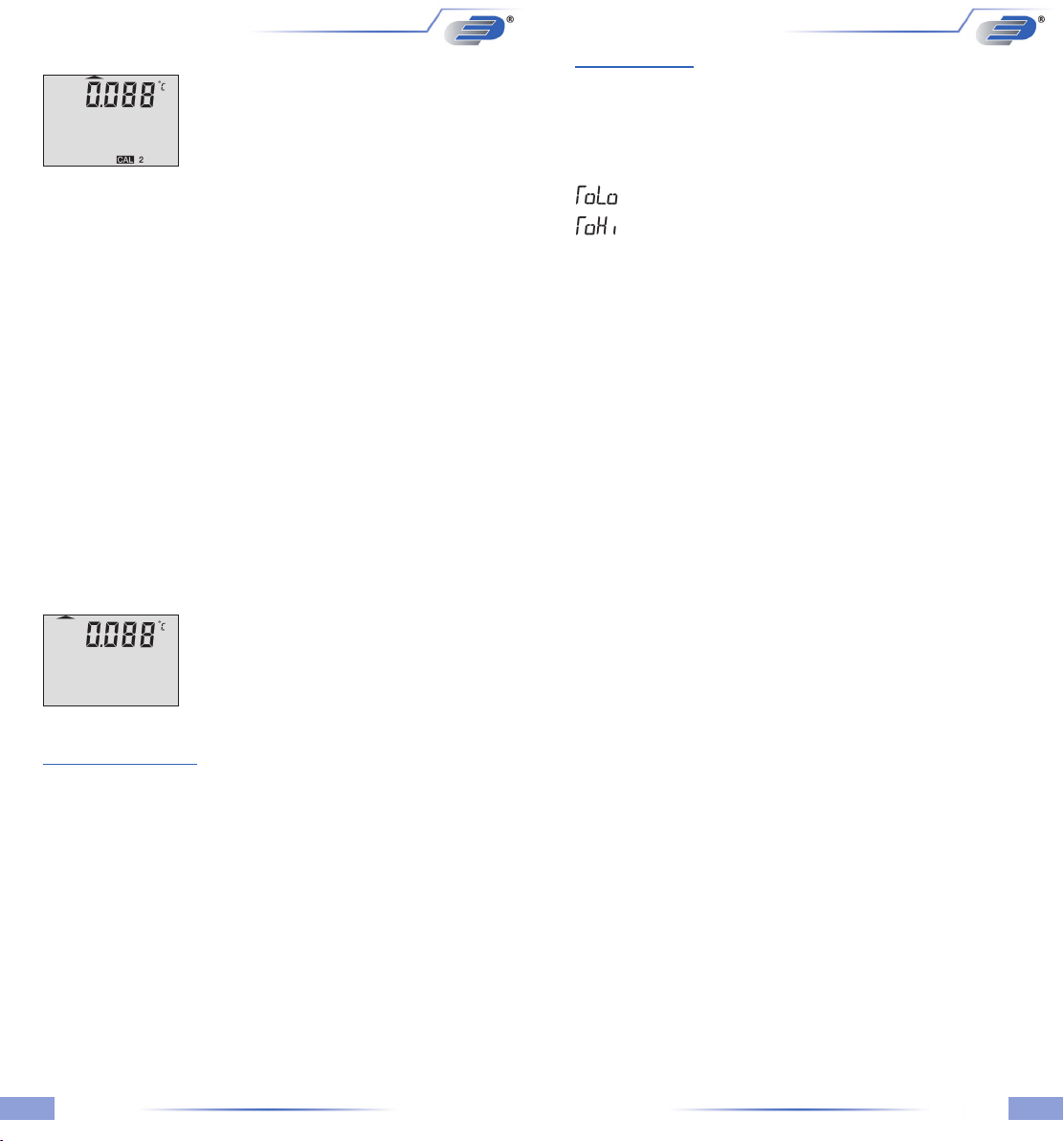
Beispiel der Messwertanzeige im Filter-Mode:
3. Fehlermeldungen
Bei Fehlbedienungen oder Gerätestörungen unterstützt das Gerät den Bediener
durch folgende Fehlermeldungen:
Oben links über der 0 zeigt der Pfeil an, dass das
Instrument im Filter-Mode misst.
Hinweis:
Diese Einstellung wird durch das Ausschalten deaktiviert.
1.7 AUTO-OFF-Funktion
dAoF = Disable Auto-off
EAoF = Enable Auto-off
Drücken Sie die Taste (ESC/AUTO-OFF). Auf dem Display wird dAoF angezeigt.
Die Auto-Off-Funktion ist jetzt deaktiviert.
Drücken Sie erneut die Taste (ESC/AUTO-OFF) einmal. Auf dem Display wird
EAoF angezeigt. Das Messgerät schaltet sich jetzt nach 30 Min. automatisch ab.
Hinweis:
Diese Einstellung wird durch das Ausschalten deaktiviert (Standard-Einstellung
ist EAoF).
1.8 TARA-Funktion (ZERO-Taste F1)
Das Messgerät verfügt über eine TARA-Funktion (ZERO-Funktion). Bei Verwendung dieser Funktion wird der zu letzt gemessene Messwert vom aktuellen
Messwert jeweils abgezogen und als neuer Messwert angezeigt. Drücken Sie
die Taste (F1) einmal. Durch wiederholtes Drücken der Taste (F1) gelangen Sie
wieder in den Normal-Mode.
Beispiel der Messwertanzeige im Zero-Mode:
Oben links zeigt der Pfeil an, dass sich das Instrument
im TARA-Mode (F1) bendet.
Error Bedeutung
oPEn falscher Fühler oder kein Fühler angeschlossen
„too low“ Messbereichsunterschreitung
„too high“ Messbereichsüberschreitung
E15 Batterie komplett verbraucht
E19 Batterie komplett verbraucht
E1d Batterie komplett verbraucht
E16 Unterbrechung durch Auto-off-Funktion (Gerät neu einschalten)
E1e Unterbrechung durch Auto-off-Funktion (Gerät neu einschalten)
E23 RAM-Inhalt zerstört (Einstellungen überprüfen)
E25 EE-prom-Inhalt zerstört
E31 Schnittstellenfehler
LoLi interne Pufferbatterie (CR2032) leer
(zum Wechseln der Batterie ist das Gehäuse aufzuschrauben)
Hinweis:
Schadhafte oder leere Batterien können Messfehler oder Fehlermeldungen
erzeugen. Bei Fehlermeldungen die Batterie entnehmen und ca. 3 Min. warten,
bevor eine neue Batterie eingelegt wird.
Hinweis: Diese Einstellung wird durch das Ausschalten deaktiviert.
2. Spannungsversorgung
- Als Spannungsversorgung des Gerätes dient eine 9V Blockbatterie.
Zum Wechseln der Batterie das Instrument ausschalten und das auf der
Rückseite angebrachte Batteriefach öffnen. Die Batterie entnehmen und eine
neue Batterie einlegen.
- Das leere Batterie-Symbol zeigt an, dass Sie die Batterie in Kürze
auswechseln müssen. Sie können jetzt noch ca. 1 Std. korrekte Messungen
durchführen.
- Das Batteriesymbol zeigt je nach Zustand bis zu 3 Segmente an.
Achtung:
Bitte entsorgen Sie Altgeräte und leere Batterien nicht über den Hausmüll. Geben
Sie diese bitte zur umweltgerechten Entsorgung beim Handel oder entsprechenden
Sammelstellen gemäß nationaler oder lokaler Bestimmungen ab.
1110
Page 7
Summary
1. Handling 12
1.1. General advices 12
1.2. Setting to work 12
1.3. Switch on/off 12
1.4. Menu 12
1.4.1. Measuring unit switching (Unit) 13
1.4.2 Automatische Fühlererkennung (Smartprobes) 13
1.4.3 Probe selection / (Prob) 13
1.4.4 Difference temperature (L in2) 14
1.4.5 Calibration (CAL) 14
1.4.6 Channel activation (Chnl) 17
1.4.7 Memory setup (Lo6) 17
1.4.8 Bluetooth activation (bLE) 18
1.5. Recalling memory data (HOLD/MAX/MIN/AVG) 18
1.6. Measuring rate (FAST-Mode) 18
1.7 AUTO-OFF4unction 19
1.8. TARE-Function (ZERO-Mode F1) 19
2. Power supply / Changing the battery 19
3. Error codes / troubleshooting 20
...............................................................................................................................
1. Handling
1.1 General advices
- For cleaning the instrument please do not use abrasive cleaner but a dry or
wet piece of cloth.
- Please store the measuring instrument in a dry and clean place.
- Avoid any force like shocks or pressure to the instrument.
- Do not use force to connect the probe or interface plugs in. The interface
plug is different from the probe plug.
- lf no sensor is connected to the instrument while switching on „open“
shows on the display (Please refer to chapter error codes / troubleshooting).
- A retractable stand on the back of the instrument allows it to be used as a
bench top instrument.
1.2 Operation
Before switching on the instrument, connect the probe/s to the instru ment and
insert the battery (Please refer to chapter 2. Power supply/changing the battery).
A number an the instrument‘s housing marks each port.
1.3 Switching on and off
By operating the ON/OFF-key the instrument switched on or off. After switching
on the instrument indicates a full segment test for 15 seconds, then it starts to
function in measurement mode indicating the actual measurement value.
1.4 Menu
The adjustments of the instruments function: measurement value, calibration
of probes, deactivation of channels, for example, are selected from the menu
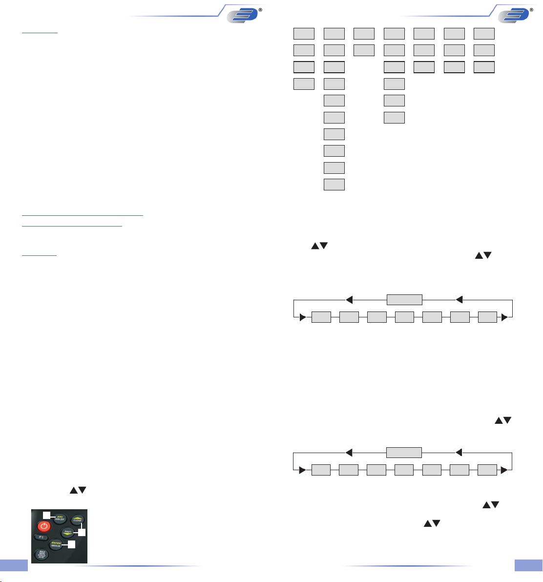
structure. Enter into the main menu by push ing (ENTER/ MENUE). Use the up
and down keys (
to the measuring mode.
1.
1. (ESC) key
2. Up and down keys
3. (ENTER/MENUE) key
) to select the required menu. Push (ESC) to revert back
2.
3.
Menu structure
Unit
Prob
°C
°F
L in 2
PT
T1-T2
J
0
K
L
N
CAL
CoFF
oP 1
oP 2
oP 3
oP 4
ChnI
oFF
on
Lo6
oFF
on
bLE
oFF
on
R
S
T
RH
1.4.1 Measuring unit switching °C, °F and Resistance (Ohm‘s) (Unit)
Unit = Measuring unit
Measuring unit temperature (°C=Celsius, °F=Fahrenheit, o=Ohm)
To change the measuring unit push (ENTER/MENUE). Use the up and down
keys (
of the display appears °C, °F or o. Use the up and down keys ( ) again to
adjust the requested measuring unit and push (ENTER/MENUE) to conrm. Push
(ESC) to be back in the measuring mode.
1.4.2 Automatische Fühlererkennung (Smartprobes)
The Instrument detect Smartprobes with Eprom automatically. It is not necessary
to select this probes by the menu function Prob! After switching on the displays
option CAL 4 (1 sensor with Eprom) or CAL 44 (2 sensors with Eprom).
1.4.3 Probe selection / (Prob)
In case of using probes of the instrument series (P700-P770) please select
probes according to the following description.
Push (ENTER/MENUE) to change a probe. Use the up and down keys ( ) to
select Prob. Push (ENTER/MENUE) to conrm.
On the left corner of the display appears a small 1, which indicates the selected
channel. For changing the channel use the up and down keys ( ). Push
again (ENTER/MENUE) to conrm. On the right corner of the display appears
the active probe. Use the up and down keys ( ) to change the probe. Push
(ENTER/MENUE) to conrm the requested probe. Push (ESC) to be back in the
measuring mode.
) to select Unit. Push again (ENTER/MENUE). On the right corner
MENUE
Unit Prob L in 2 CAL ChnI Lo6 bLE
MENUE
Unit Prob L in 2 CAL ChnI Lo6 bLE
1312
Page 8
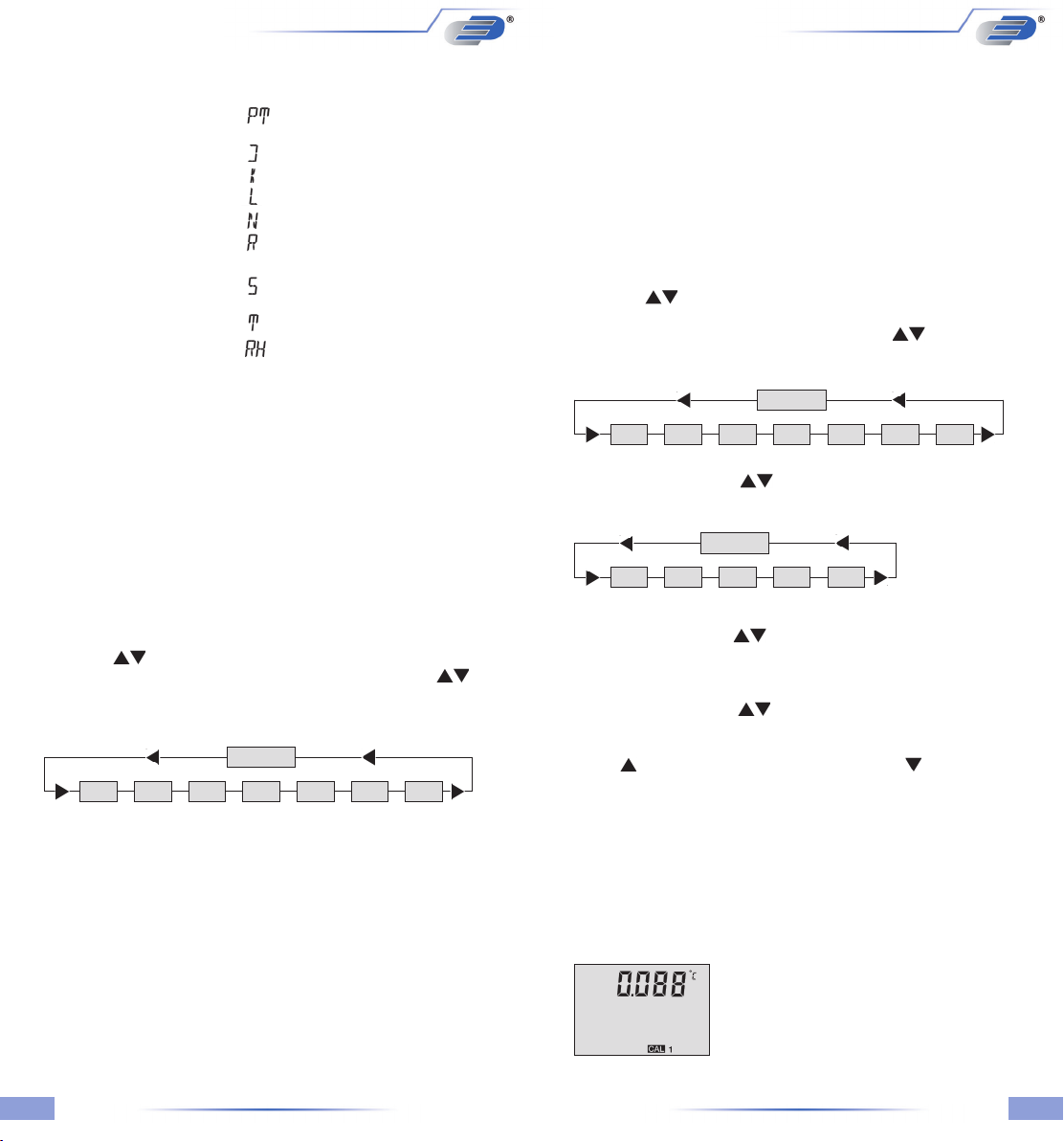
Measurement Probe selection LC-Display Suitable for these types
(Prob) of measuring instruments:
...............................................................................................................................
Temperature Pt100 (RTD) P700/P705/P750/P755/
P770/P755-LOG/P770-LOG
...............................................................................................................................
Temperature Fe-CuNi Typ J for all P700-instruments
...............................................................................................................................
Temperature NiCr-Ni Typ K for all P700-instruments
...............................................................................................................................
Temperature Fe-CuNi Typ L for all P700-instruments
...............................................................................................................................
Temperature NiCrSi-NiSi Typ N for all P700-instruments
...............................................................................................................................
Temperature Pt13Rh-Pt Typ R P700/P705/P750/P755/
P770/P755-LOG/P770-LOG
...............................................................................................................................
Temperature Pt10Rh-Pt Typ S P700/P705/P750/P755/
P770/P755-LOG/P770-LOG
...............................................................................................................................
Temperature Cu-CuNi Typ T for all P700-instruments
...............................................................................................................................
Humidity %rF P700/P705/P750/P755/
P770/P755-LOG/P770-LOG
...............................................................................................................................
Push (ENTER/MENUE) to conrm. Push (ESC) to revert back to the measuring
mode.
Note: Please check the probe selection to be sure that the correct probe is
entered. If a measurement value is changed with the ENTER-key at the menu
Prob, the standard calibration will be automatically used.
Indications for the combination probes (temperature and humidity):
Please adjust relatively humidity as measurement value for the channel on which
the combination probe is plugged. If you want that the measured temperature
of the plugged combination probe is shown as well, you have to deactivate the
channel on which no probe is plugged on (see chapter 1.4.6./Chnl)
The instruments offer ve different calibration options:
1) (CoFF): Standard characteristic curve
(e.g. Pt100-resistance according EN60751)
2) (oP 1): Calibration by code (2 x four digit code) is equivalent to a 2-point
calibration. The code is marked clearly by a label on each standard
probe.
3) (oP 2): Calibration by physical standard references
(1-point, 2-point or 3-point calibration)
4) (oP 3): Calibration according to Coefcients of EN60751 (RO, ABC)
5) (oP 4): Smart EEprom probes with internal calibration
CAL = calibration
Push (ENTER/MENUE) to calibrate the instrument with sensor. Use the up and
down keys (
) to select CAL. Push again (ENTER/ MENUE). On the left
corner of the display appears a small 1, which indicates the selected channel. To
change the channel (1 or 2) use the up and down keys ( ). Push (ENTER/
MENUE) to conrm.
MENUE
Unit Prob L in 2 CAL ChnI Lo6 bLE
Use the up and down keys ( ) to select the requested calibration option.
Push (ENTER/MENUE) to conrm.
CAL
CoFF oP 1 oP 2 oP 3 oP 4
1.4.4 Temperature difference / (L in2)
To display the temperature difference push (ENTER/MENUE). Use the up and
down keys (
corner of the display appears a T1-T2. Use the up and down keys (
) to select L in2. Push again (ENTER/MENUE). On the right
) to
adjust the requested selection. Push (ENTER/MENUE) to conrm. Push (ESC)
to revert back to the measuring mode.
MENUE
Unit Prob L in 2 CAL ChnI Lo6 bLE
Note: Both channels have to be activated for displaying temperature difference.
1.4.5 Calibration function / (CAL)
Despite high quality manufacturing techniques, each probe is slightly different
from specied standards. To eliminate inaccuracies caused by exchanging or
ageing of probes, the instrument offer easy calibration functions which guarantee
that the system accura cy is always as good as if the instrument was specically
calibrated to the individual probes in our laboratory.
1) Standard calibration according to DIN EN60751 / (CoFF)
Use the up and down keys ( ) to select (CoFF). Push (ENTER/MENUE) to
conrm. Push (ESC) to revert back to the measuring mode.
2) CaIibrationby code / oP1
Use the up and down keys ( ) to select oP 1. Push (ENTER/ MENUE) to
conrm. On the bottom of the display appears a small 1, after this number a
four-digit number (Hex-Code/0..F) is dis played. For changing the number use the
up key ( ). To step to the next number use the down key ( ). lf the requested
number is complete then push (ENTER/MENUE) to conrm. At the bottom of the
display a very small 2 appears, after which a second four-digit number is displayed.
For changing the number please follow the manual as before. Push (ESC) to
revert back to the measuring mode.
Note:
After conrming oP 1 by pushing (ENTER/MENUE) the function oP 1 (calibration
by code) is activated, even though you leave the menu by pressing (ESC).
Display-indication with active calibration code (oP 1):
The CAL-segment and the small 1 indicates to the user
that oP 1 is activated.
1514
Page 9
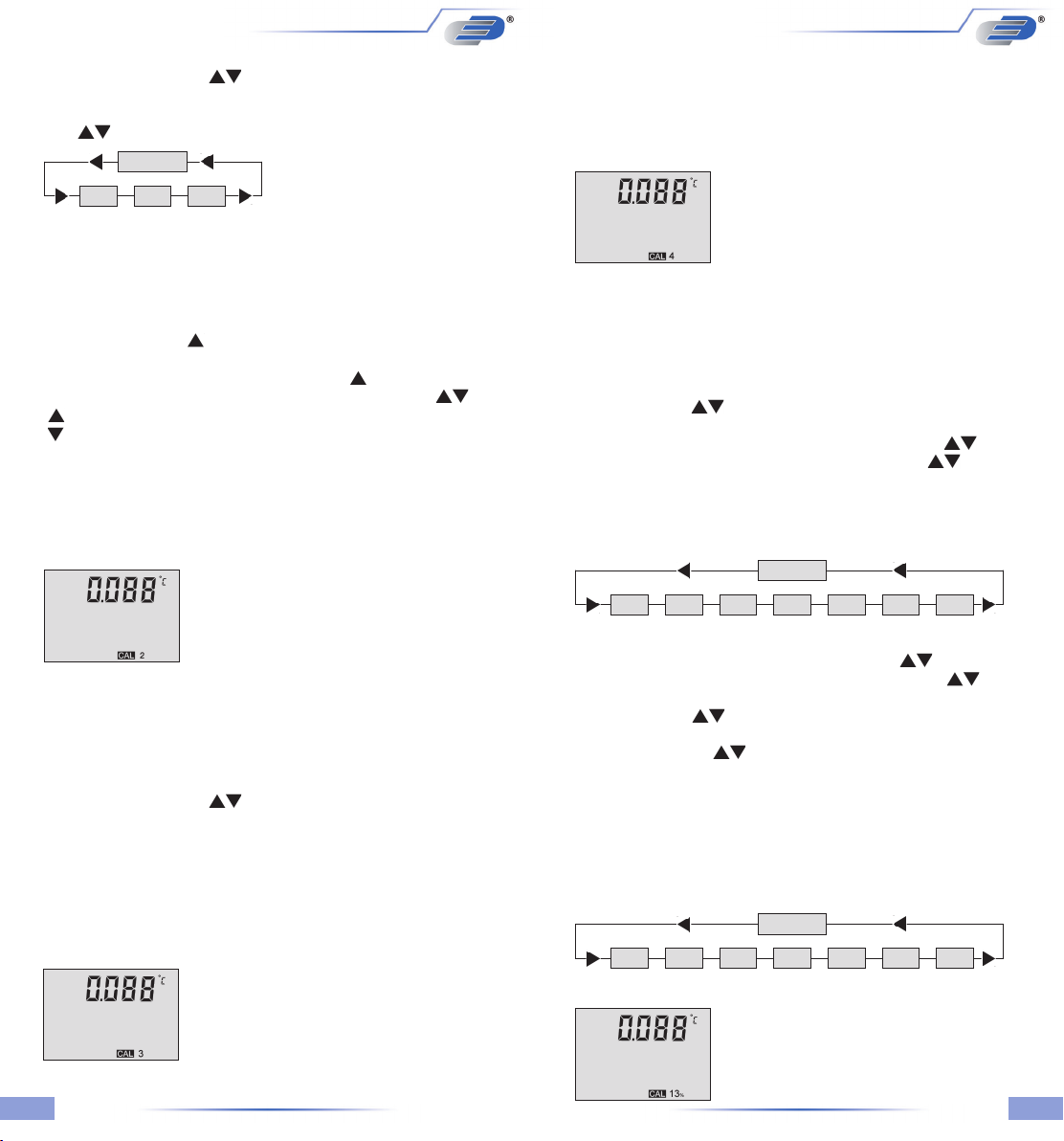
3) Calibration by physical standard references / oP 2
Use the up and down keys ( ) to select oP 2. Push (ENTER/MENUE) to
conrm. On the bottom of the display appears 1 P. For changing between a
1-Point (1 P), 2-Point (2 P) or 3-Point (3 P) - cali bration use the up and down
keys (
).
oP 2
1 P 2 P 3 P
Example of a 1-Point calibration:
Push (ENTER/MENUE) to conrm. On the display appears CALC. After the
displayed measuring value is stabile push (ENTER/ MENUE). On the rst
display line you can see the „frozen“ measure ment value. On the second
line as a default you can see -100.000. Now you have to enter (instead
of -100.000) the correct measure ment value from your reference:
By using the up key ( ) you are able to move the decimal point to
setup the number of decimal places. Push (ENTER/MENUE) to con rm.
Now the algebraic sign is blinking „-“. Use the up key ( ) to toggle for positive
or negative number. Change the number using the up and down keys ( ):
( ) is changing the blinking segment
( ) is jumping to the next segment
Push (ENTER/MENUE) to conrm, revert back to the measuring mode.
lmportant:
To abort the physical calibration use the (ESC)-button.
Display-indication with active calibration code (oP 2):
5) Smart EEprom-probes with internal calibration (AUTO-Detection) / oP 4
The Option 4 will be activated automatically by using Smart EEprom probes. This
option will be activated by switching on the instrument when the Smart EEprom
probe has been connected to the instrument.
Display-indication with active calibration code (oP 4):
The CAL-segment and the small 4 indicates to the user
that oP 4 is activated.
Note:
lf a Smart probe will be disconnected during the instrument is work ing the
instrument automatically switch to the CAL-menu.
1.4.6 Channel activation (only 2-channel instruments) / (Chnl)
Chnl = Channel
To activate or deactivate a measuring channel push (ENTER/MENUE). Use the
up and down keys ( ) to select Chnl. Push again (ENTER/MENUE). On
the left corner of the display appears a small 1, which indicates the selected
channel. To change the channel use the up and down keys ( ). Push
(ENTER/MENUE) to conrm. Use the up and down keys ( ) again to
activate on or deactivate off the requested measuring channel and push (ENTER/
MENUE) to conrm. Push (ESC) to revert back to the measuring mode.
Note: As a minimum one channel is active!
MENUE
The CAL-segment and the small 2 indicates to the user
that oP 2 is activated.
4) Calibration according to Coefcients of EN60751 (R0, ABC)/ oP 3
By using Option 3 you are able to activate coefcients according to EN60751
(RO, A, B, C). The coefcients have to be calculated using special software on
a PC (e. g. P7_CALC). Before you are able to activate this option you have to
transmit the coefcients from the PC to the instrument. Therefore you have to use
the Soft ware P7 _CALC, too.
Use the up and down keys ( ) to select oP 3. Push (ENTER/MENUE) to
conrm. Now the calibration option 3 is activated! Push (ESC) to revert back to
the measuring mode.
Note: After conrming oP 3 by pushing (ENTER/MENUE) the function oP 3
(calibration by code) is activated, even though you leave the menu by pressing
(ESC).
Display-indication with active calibration code (oP 3):
The CAL-segment and the small 3 indicates to the user
that oP 3 is activated.
Unit Prob L in 2 CAL ChnI Lo6 bLE
1.4.7 Memory Setup Lo6
Push (ENTER/MENUE) and use the up and down keys ( ) to select Lo6.
Push (ENTER/MENUE) to conrm. Use the up and down keys ( ) again
to start (on) or Stop (off) the logger. Push (ENTER/MENUE) to conrm. Use the
up and down keys ( ) again to select between automatic storage (Auto)
or manually operated storage (SPot). Push (ENTER/MENUE) to conrm. Use
the up and down keys ( ) again to select between to add on data (Add)
and creating a new le (nLo6). Push (ENTER/MENUE) to conrm. By selected
automatic storage at the end you have to select the time interval:
1 S 1 second
5 S 5 second
10 S 10 second
20 S 20 second
30 S 30 second
1 M 1 minutes
2 M 2 minutes
5 M 5 minutes
10 M 10 minutes
20 M 20 minutes
MENUE
Unit Prob L in 2 CAL ChnI Lo6 bLE
E.g. of the instrument’s LCD by activated logging mode:
On the bottom you can see the percentage of the
occupied memory (0..99%). If a calibration option is
activated the display is alternating between displaying
memory status and calibration information.
1716
Page 10
1.4.8 Bluetooth activation/deactivate / (bLE)
bLE = Bluetooth = off / on
To activate or deactivate bluetooth push (ENTER/MENUE). Use the up and
down keys ( ) to select bLE. Push again (ENTER/MENUE). Use the up key
( ) to activate on or deactivate off the bluetooth function and push (ENTER/
MENUE) to conrm. Push (ESC) to revert back to the measuring mode.
1.7 AUTO-OFF-function
dAoF = Disable Auto-off
EAoF = Enable Auto-off
Press (ESC/AUTO-OFF) key once. On the display appears EAoF. Now the
instrument switches off automatically after app. 30 minutes. Press (ESC/AUTO-OFF) key again. On the display appears dAoF. Now the Auto-Off-function
is deactivated.
MENUE
Unit Prob L in 2 CAL ChnI Lo6 bLE
1.5 Recalling the memory data (HOLD MAX MIN AVE)
After pushing rst time the key (HOLD MAX MIN AVE) the actual values will be
held on the display. Pushing again the key (HOLD MAX MIN AVE), the saved
maximum-, minimum and average values will be displayed.
Note: During the recall of the memory data the extremes (MAX MIN) and the
average value (AVE) will not be calculated or carried on.
Clearing the memory (MAX MIN AVE)
Press (CLEAR) key once to erase the stored maximum, minimum and average
from memory. On the display appears Clr. – After erasing the memory the
instrument automatically reverts back to measuring mode indicating the actual
measured value again.
1.6 Measuring rate (Normal-Mode / FAST-Mode / Filter-Mode)
The instrument has three different response times to select:
Normal-Mode: high resolution
(0.001 from -199.999 to +199.999)
FAST-Mode: reduced resolution
(0.01 from -199.99 to +199.99)
Filter-Mode: high resolution
(0.001 from -199.999 to +199.999)
Press (FAST /
) key to change the measuring rate. By using the FilterMode the instrument is performing a moving average to stabilize the dispayed
measurements. After turning on the instrument it is in the Normal-Mode. After
pressing once the (FAST / ) key the instrument switches to the Fast-Mode.
Pressing the same key once again the instrument switches to the Filter-Mode.
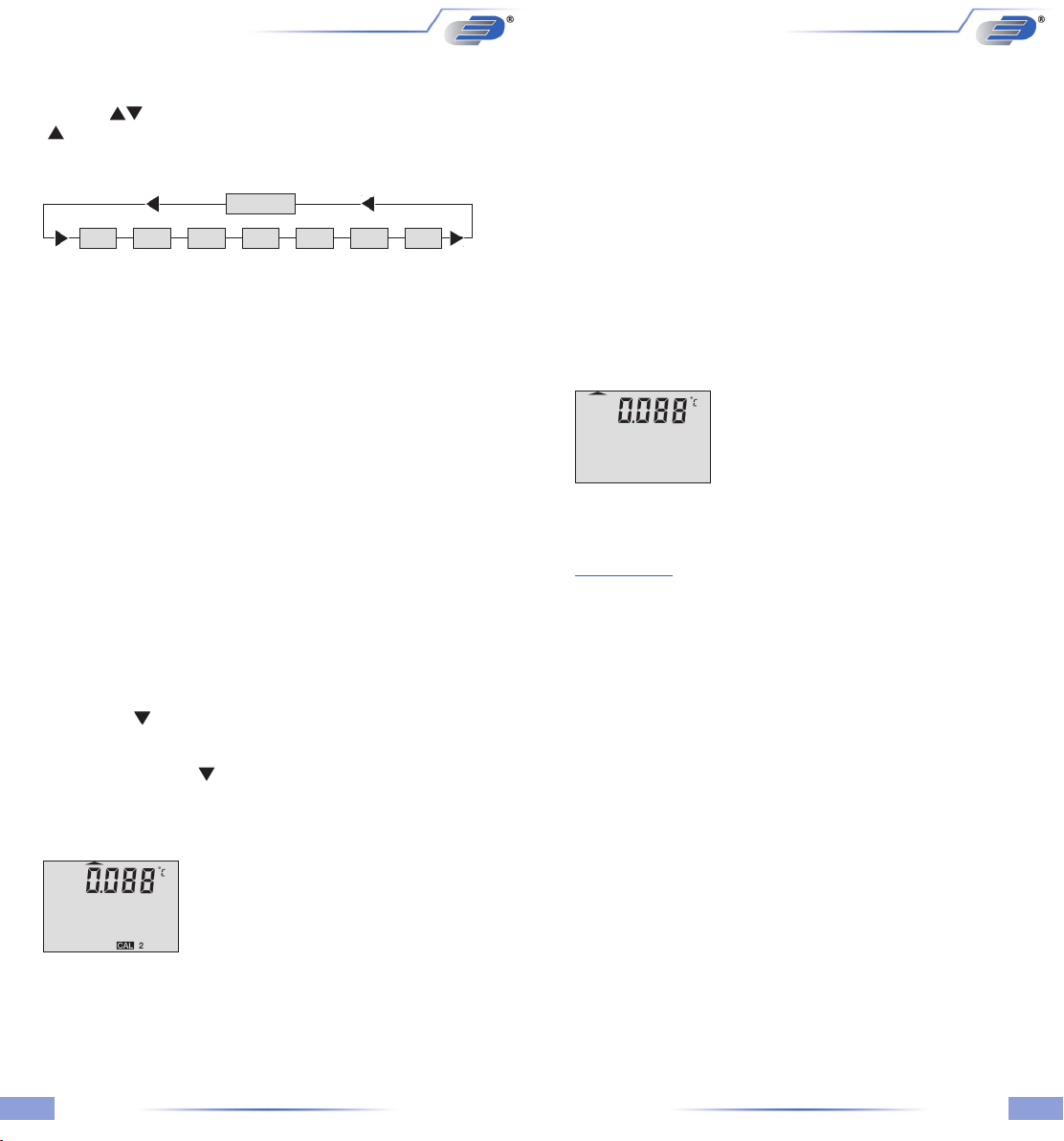
E.g. Display with activated Filter-Mode:
Attention: This setting will be deactivated when the instrument turns off.
(Standard setting is EAoF).
1.8 TARE-Function (ZERO-Mode F1)
The Instrument has a special Tare/Zero-button. Pressing the (F1) key once, the
instrument will subtract the last measured value from the actual measured value.
So if the measurement does not change zero appears on the instrument’s display.
If you press the (F1) key once again the instrument move to the Normal-Mode.
E.g. Display with activated Zero-Mode:
The arrow on the left indicates that the instrument is
working in the Zero-Mode (F1).
Note: After switching off the instrument, this function is automatically deactivated.
2. Power supply
- For the power supply of the instrument a 9 Volt dry battery is used.
To exchange the battery switch of the instrument and open the rear battery
cover. Remove the battery from the instrument and replace with a new battery.
- The “BAT” symbol in the display indicates that the battery needs to be
exchanged. After displaying the “BAT” symbol, the instrument allows
app. 1 hour of further operation.
- The battery symbol indicates according to the battery status between
1 to 3 segments.
Attention:
Please do not dispose of old electronic devices and empty batteries in household
waste. To protect the environment, take them to your retail store or to appropriate
collection sites according to national or local regulations.
The arrow on the top indicates that the instrument is
working in the Filter-Mode.
Note: After switching off the instrument, this function is automatically deactivated.
1918
Page 11
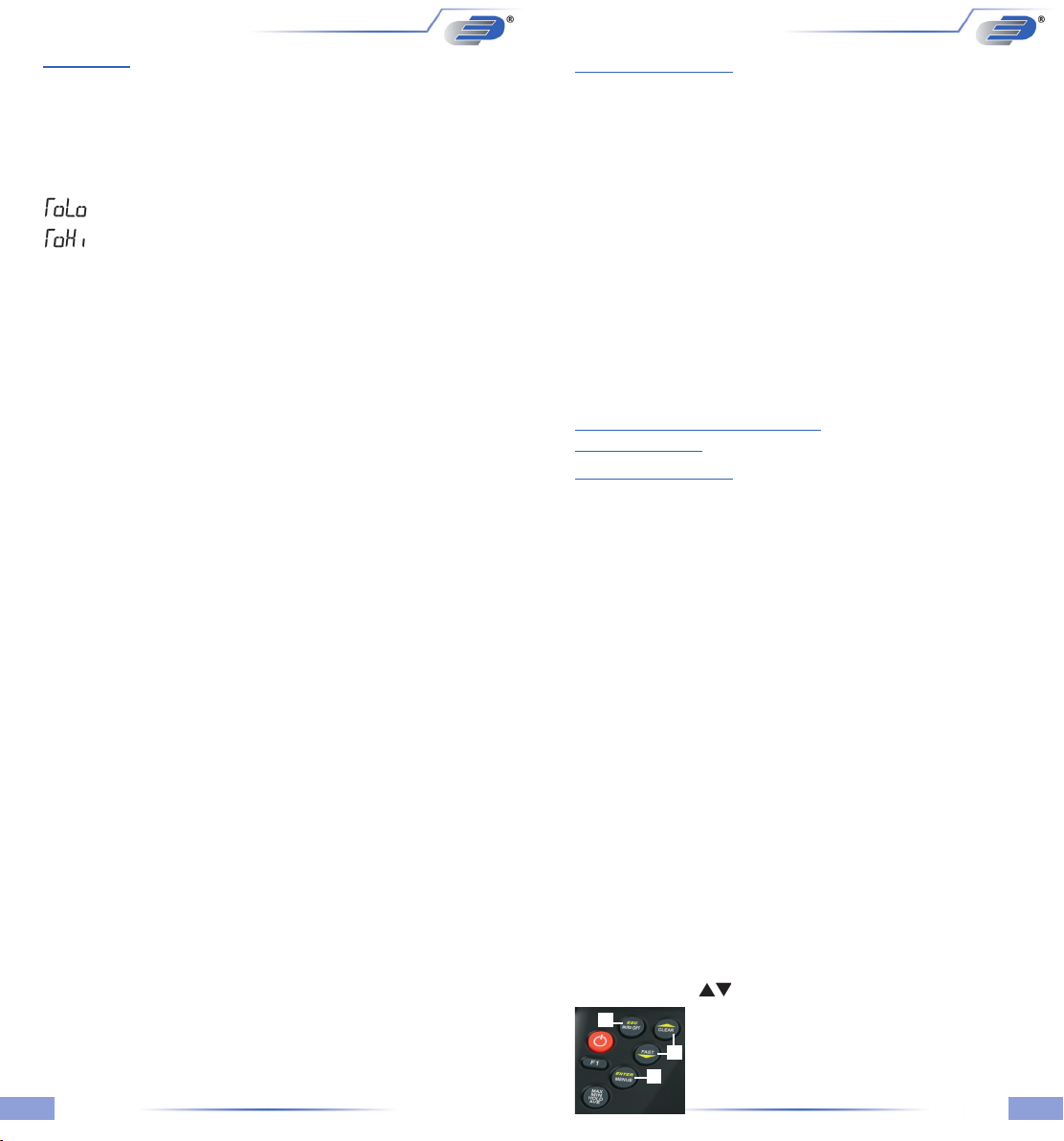
3. Error Codes
By displaying the following error codes the instrument support the operation of
the instrument:
Error Meaning
oPEn no probe or wrong probe is connected
„too low“ underow of the measuring range
„too high“ exceeding of the measuring range
E15 low battery (battery is completely exhausted)
E19 low battery (battery is completely exhausted)
E1d low battery (battery is completely exhausted)
E16 time out / auto-off-function (Switch device on again)
E1e time out / auto-off-function (Switch device on again)
E23 RAM content destroyed (check settings)
E25 EE-prom destroyed or EE-prom index is wrong
E31 Interface error
LoLi internal buffer battery (CR2032) empty
(for changing the battery the housing must be unscrewed)
Hinweis:
Hint: Defective or empty batteries can cause measurement errors or error
messages. On error messages, remove battery and wait 3 minutes prior to
mounting a new battery.
Table des matières
1. Utilisation / introduction 21
1.1. Remarques 21
1.2. Mise en service 21
1.3. Mise en marche/arrêt 21
1.4. Structure du menu 21
1.4.1. Changement des unités (unit) 22
1.4.2 Détection automatique du capteur (Smart Probes) 22
1.4.3 Choisir une sonde / (Prob) 22
1.4.4 Différence de température (L in2) 23
1.4.5 Fonction d’étalonnage (CAL) 23
1.4.6 Activer les canaux (Chnl) 26
1.4.7 Utilisation de la mémoire (Lo6) 26
1.4.8 Bluetooth 27
1.5. Interrogation de la mémoire (HOLD/MAX/MIN/AVG) 27
1.6. Changer le cycle de mesure (mode FAST) 27
1.7. Fonction ARRÊT AUTO 28
1.8. Fonction TARA (bouton ZERO F1) 28
2. Alimentation / remplacement de la pile 28
3. Messages d’erreur 29
...............................................................................................................................
1. Utilisation / introduction
- Pour nettoyer l’instrument de mesure, n’utilisez pas de détergent agressif
mais un chiffon sec ou humide.
- Rangez l’instrument de mesure dans un endroit sec et propre.
- Ne soumettez pas l’appareil à des impacts violents tels que les chocs ou
écrasements.
- N’insérez pas avec force la che dans la prise. Les ches du canal de
mesure et de l’interface sont différentes.
- Si aucune sonde n‘est branchée lorsque vous mettez l’instrument de
mesure en marche, l’écran afche «open». (Veuillez vous référer au
chapitre Messages d‘erreur).
1.2 Mise en service
Avant la mise en service, raccordez la/les sonde(s) à votre instrument de mesure
et assurez-vous qu’une pile de 9 V y est bien insérée. (2 piles sont fournies). Les
ches de raccordement de sonde sont marquées sur le boîtier de l’appareil par 1
(canal 1), 2 (canal 2), et USB.
1.3 Mise en service/arrêt
Appuyez sur le bouton ON/OFF pour mettre l’instrument de mesure sous et hors
tension. Après la mise sous tension, tous les segments apparaissent pendant
env. 1,5 s sur l’écran (afchage à segments pleins); puis, l’instrument passe en
mode de mesure et afche la valeur de mesure actuelle. Dans la ligne supérieure
de l’écran apparaît la valeur de mesure pour le canal 1. La valeur de mesure pour
le canal 2 apparaît plus bas.
1.4 Structure de menu
Les réglages de l’appareil comme les valeurs de mesure, les étalonnages de la
sonde, désactiver les canaux, etc. s’effectuent via une arborescence du menu.
Vous accédez au menu principal en appuyant sur le bouton (ENTER/MENUE).
Les boutons échés (
menu souhaités. Appuyez sur le bouton ESC pour
1.
revenir au mode de mesure.
1. Boutons échés
2. Touches échées
2.
3.
) vous permettent de sélectionner les éléments de
3. Bouton (ENTER/MENUE)
2120
Page 12
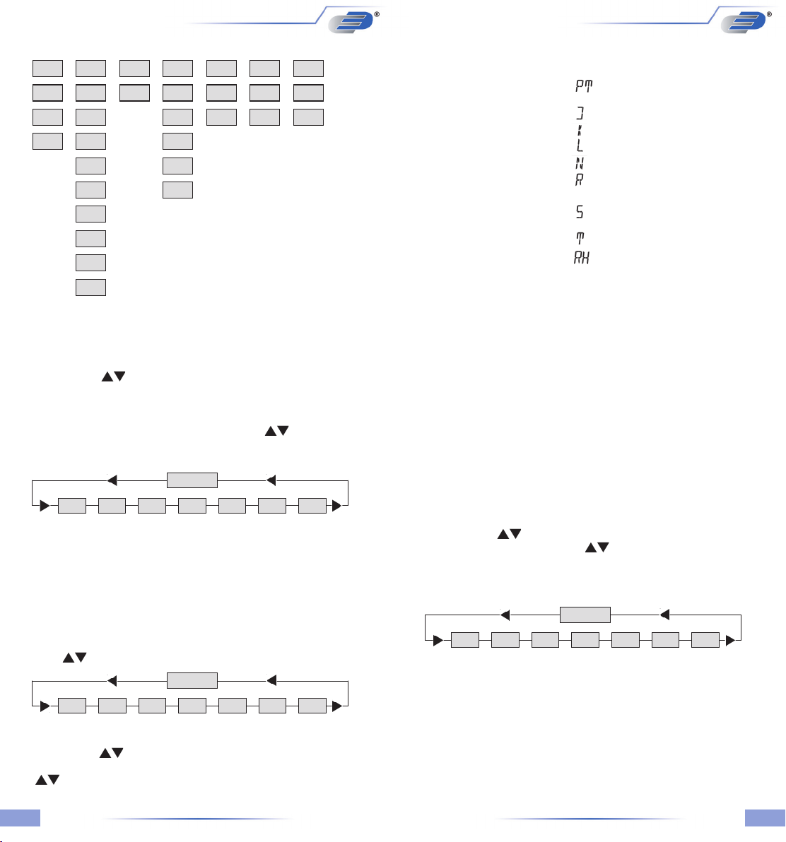
Arborescence du menu
Unit
Prob
°C
°F
L in 2
PT
T1-T2
J
0
K
L
N
CAL
CoFF
oP 1
oP 2
oP 3
oP 4
ChnI
oFF
on
Lo6
oFF
on
bLE
oFF
on
R
S
T
RH
1.4.1 Changement des unités °C, °F et Ohm (Unit)
Unit = unité
Unité de mesure de la température (°C=Celsius, °F=Fahrenheit, o=Ohm)
Appuyez sur le bouton (ENTER/MENUE) et sélectionnez Unit à l’aide des
boutons échés (
fonction du capteur sélectionné (voir chapitre 1.4.2+1.4.3 Choisir une sonde / (Prob),
°C ou °F s’afche maintenant sur le côté droit de l’écran. La lettre o (pour ohm)
s’afche en vue de la sélection dans la partie inférieure droite de l‘écran. Choisissez l’uni-té souhaitée à l’aide des boutons échés ( ) et validez avec
(ENTER/MENUE). Le bouton (ESC) vous permet d’accéder de nouveau au mode
de mesure.
Unit Prob L in 2 CAL ChnI Lo6 bLE
1.4.2 Détection automatique du capteur (Smart Probes)
Le capteur intelligent avec Eprom détecte automatiquement le compteur. Une
sélection de sondes dans le menu Prob n‘est pas nécessaire! L‘appareil afche
l‘option CAL 4 (1 capteur avec Eprom) ou CAL 44 (2 capteurs avec Eprom) après
la mise sous tension.
1.4.3 Choisir une sonde / (Prob)
Appuyez sur la touche (ENTER/MENUE) et choisissez Prob avec les touches
èche ( ), puis appuyez encore une fois sur (ENTER/MENUE).
Unit Prob L in 2 CAL ChnI Lo6 bLE
Du côté gauche de l’écran LCD un petit 1 apparaît qui indique le canal. Avec les
touches èche ( ), vous pouvez changer le canal pour lequel vous voulez
choisir une sonde. Valider avec la touche (ENTER/MENUE). Avec les èches
( )vous pouvez choisir les sondes:
). Ensuite, appuyez de nouveau sur (ENTER/MENUE). En
MENUE
MENUE
Valeur Choix de la sonde LCD-Afchage Compatible avec les
de mesure (Probe) instruments de mesure:
...............................................................................................................................
Température Pt100 (RTD) P700/P705/P750/P755/
P770/P755-LOG/P770-LOG
...............................................................................................................................
Température Fe-CuNi Typ J pour tous les appareils P700
...............................................................................................................................
Température NiCr-Ni Typ K pour tous les appareils P700
...............................................................................................................................
Température Fe-CuNi Typ L pour tous les appareils P700
...............................................................................................................................
Température NiCrSi-NiSi Typ N pour tous les appareils P700
...............................................................................................................................
Température Pt13Rh-Pt Typ R P700/P705/P750/P755/
P770/P755-LOG/P770-LOG
...............................................................................................................................
Température Pt10Rh-Pt Typ S P700/P705/P750/P755/
P770/P755-LOG/P770-LOG
...............................................................................................................................
Température Cu-CuNi Typ T pour tous les appareils P700
...............................................................................................................................
Humidité %rF P700/P705/P750/P755/
P770/P755-LOG/P770-LOG
...............................................................................................................................
Conrmez votre choix avec (ENTER/MENUE). Avec la touche (ESC), vous
retournez dans le mode de mesure.
Important!
Remarque: Assurez-vous que la valeur mesurée correspond à la sonde choisie.
Si la valeur de mesure change, conrmez avec la touche (ENTER) dans le menu
Prob, le calibrage standard est automatiquement effectivé.
Important!
Remarque de la sonde combinée (température et humidité):
Choisissez l’humidité relative comme grandeur de mesure pour le canal sur
lequel la sonde combinée est branchée. Si vous voulez également voir la
températu-re de cette sonde combinée il faut désactiver le canal où la sonde
combinée n’est pas branchée (Voir le chapitre 1.4.6/Chnl).
1.4.4 Activer/désactiver l’option d’afchage Différence de
température (L in2)
Appuyez sur le bouton (ENTER/MENUE) et sélectionnez L in2 à l’aide des
boutons échés (
MENUE). Utilisez les boutons échés ( ) pour activer l’afchage Différence
de température (T1-T2) ou le désactiver (T1-T2 visible sur l‘écran LCD = différence
de température active). Validez le réglage souhaité avec (ENTER/MENUE). Le
bouton (ESC) vous permet d’accéder de nouveau au mode de mesure.
Unit Prob L in 2 CAL ChnI Lo6 bLE
Remarque: Pour afcher la différence de température, les deux canaux
doivent être activés.
1.4.5 Fonction d’étalonnage / (CAL)
Votre instrument de mesure vous offre la possibilité, lors du remplacement des
sondes, d’effectuer un étalonnage simple an de compenser les tolérances des
sondes attribuables à la fabrication et garantir une précision constante élevée de
votre chaîne de mesure.
). Ensuite, appuyez de nouveau sur le bouton (ENTER/
MENUE
2322
Page 13
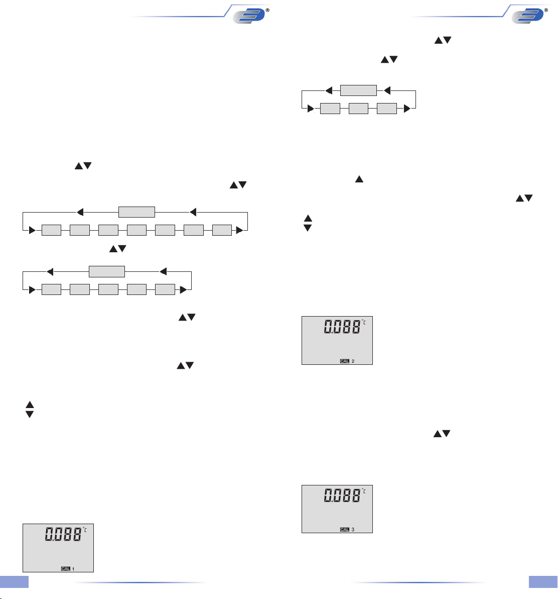
L’appareil offre 5 différents modes d’étalonnage:
1) (CoFF): Courbe caractéristique standard
(p. ex. pour des mesures de résistance Pt100 EN60751)
2) (oP 1): Etalonnage numérique
(le code de 2 x 4 chiffres est apposé de manière visible sur la
poignée de nos sondes) correspond à un étalonnage en 2 points
3) (oP 2): Etalonnage physique
(étalonnage avec étalons de comparaison:
un étalonnage en 1 point, 2 points ou 3 points est possible)
4) (oP 3): Coefcients d’étalonnage selon EN60751 (R0, ABC)
5) (oP 4): Capteur EEprom avec étalonnage (détection automatique)
CAL = Etalonnage
Appuyez sur le bouton (ENTER/MENUE) et sélectionnez CAL à l’aide des
boutons échés ( ). Ensuite, appuyez de nouveau sur (ENTER/MENUE).
Un petit 1 indiquant le canal apparaît alors sur le côté gauche de l’écran.
Choisissez le canal (1 ou 2) à étalonner à l’aide des boutons échés ( ) et
validez avec (ENTER/MENUE).
MENUE
Unit Prob L in 2 CAL ChnI Lo6 bLE
Utilisez les boutons échés ( ) pour sélectionner la fonction d’étalonnage
souhaitée.
CAL
CoFF oP 1 oP 2 oP 3 oP 4
1) Etalonnage DIN EN60751 / (CoFF)
Sélectionnez (CoFF) à l’aide des boutons échés ( ). Validez le réglage
souhaité avec (ENTER/MENUE). Le bouton (ESC) vous permet d’accéder de
nouveau au mode de mesure.
2) Etalonnage numérique / oP1
Sélectionnez oP 1 à l’aide des boutons échés ( ). Validez le réglage
souhaité avec (ENTER/MENUE). Il s’afche un petit 1 dans la partie inférieure de
l’écran. Derrière, il y a 4 positions (code Hex /0..F).
Vous pouvez modier les 4 positions en utilisant le bouton éché vers le haut
( ). Vous passez à la prochaine position à l’aide du bouton éché vers le bas
( ). Une fois que vous avez entré les 4 positions comme souhaité, validez
avec (ENTER/MENUE). Un petit 2 apparaît alors et vous pouvez modier les 4
positions suivantes de la même façon. Le bouton (ESC) vous permet d’accéder
de nouveau au mode de mesure.
3) Etalonnage physique / oP 2
Sélectionnez oP 2 avec les boutons échés ( ) Validez le réglage souhaité
avec (ENTER / MENUE). Il s’afche alors 1P dans la partie inférieure de l’écran.
Avec les boutons échés ( ), vous pouvez choisir entre un étalonnage en
1 point (1 P), en 2 points (2 P) ou en 3 points (3 P).
oP 2
1 P 2 P 3 P
Exemple d’un étalonnage en 1 point:
Validez l’étalonnage en 1 point 1 P avec (ENTER/MENUE). CALC apparaît alors
sur l’écran. Dès que la valeur mesurée se stabilise, validez avec (ENTER/MENUE).
La dernière valeur de mesure afchée apparaît sur la première ligne de l’écran,
-100.000 apparaît sur la deuxième ligne de l’écran comme valeur prédénie.
Le bouton CLEAR (
) vous permet de déplacer le point décimal et de sélectionner le
nombre de décimales souhaité. Validez le réglage souhaité avec (ENTER/MENUE).
Le signe «-» clignote maintenant sur l’écran. Utilisez les boutons échés (
pour modier le signe et les chiffres:
) modie le segment clignotant (chiffre ou signe)
(
( ) commute sur le prochain segment (chiffre ou signe)
(A ce stade, vous pouvez entrer la température de référence.) Validez le réglage
souhaité avec (ENTER/MENUE). Vous retournez alors au mode de mesure.
Important:
L’annulation de l’étalonnage physique oP 2 s’effectue avec le bouton ESC.
Exemple d’afchage de valeurs de mesure après un étalonnage physique avec
un étalon de comparaison:
Le petit 2 en bas à droite en relation avec le segment
d’afchage CAL vous montre que l’étalonnage
numérique oP 2 a été activé.
4) Etalonnage selon Callendar et van Dusen / oP 3
L’option 3 sert à activer les coefcients d’étalonnage selon Callendar et van
Dusen (R0,ABC). Les coefcients d’étalonnage doivent être au préalable
transférés à l’instrument de mesure via un PC. Un logiciel P7_CALC est
nécessaire à cet effet.
Sélectionnez oP 3 avec les boutons échés ( ). Validez le réglage souhaité
avec (ENTER/MENUE).
)
Important:
Lorsque vous appelez oP 1 avec (ENTER/MENUE), la fonction oP 1 (étalonnage
numérique) est activée même lorsque vous avez quitté le menu avec (ESC).
Exemple d’afchage de valeurs de mesure après entrée d’un numéro
d’étalonnage de la sonde:
Le petit 1 en bas à droite en relation avec le segment
d’afchage CAL vous montre que l’étalonnage
numérique oP 1 a été activé.
Exemple d’afchage de valeurs de mesure après un étalonnage physique avec
un étalon de comparaison:
Le petit 3 en bas à droite en relation avec le segment
d’afchage CAL vous montre que l’étalonnage
numérique oP 3 a été activé.
2524
Page 14
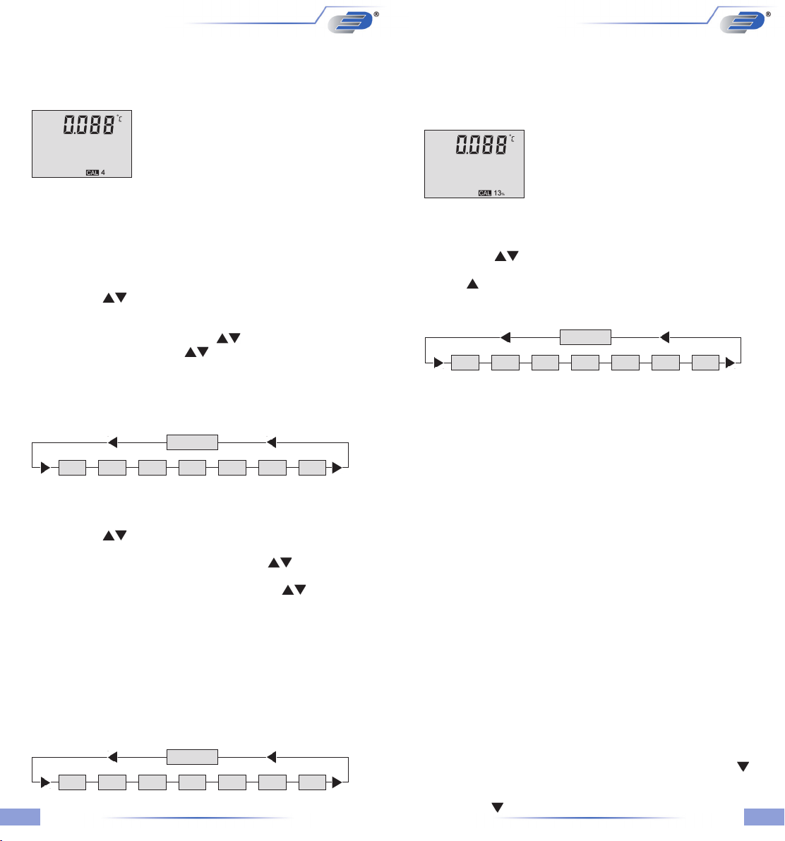
5) Capteur EEprom avec étalonnage (détection automatique) / oP 4
L’option 4 est automatiquement activée si, lors de la mise en marche de
l’instrument de mesure, un capteur avec EEprom intégrée est connecté.
Exemple d’afchage de valeurs de mesure après un étalonnage physique avec
un étalon de comparaison:
Le petit 4 en bas à droite en relation avec le segment
d’afchage CAL vous montre que l’étalonnage
numérique oP 4 a été activé.
Important:
Si un capteur EEprom est débranché lors de la mise en marche de l’instrument,
ce dernier appelle automatiquement le menu CAL.
1.4.6 Activer/désactiver les canaux de mesure / (Chnl)
Chnl = Channel = sélectionner
Appuyez sur le bouton (ENTER/MENUE] et sélectionnez Chnl à l’aide des
boutons échés ( ).
Ensuite, appuyez de nouveau sur (ENTER/MENUE). Un petit 1 indiquant le canal
apparaît alors sur le côté gauche de l’écran. Choisissez le canal à activer ou
désactiver à l’aide des boutons échés (
) et validez avec (ENTER/
MENUE). Avec les boutons échés ( ), vous pouvez maintenant activer le
canal choisi on ou le désactiver off. Validez le réglage souhaité avec (ENTER/
MENUE). Le bouton (ESC) vous permet d’accéder de nouveau au mode de
mesure.
Important: Au moins un canal demeure toujours actif!
MENUE
Unit Prob L in 2 CAL ChnI Lo6 bLE
1.4.7 Gestion de la mémoire Lo6
Appuyez sur le bouton (ENTER/MENUE) et sélectionnez Lo6 à l’aide des
boutons échés ( ).
Ensuite, appuyez de nouveau sur (ENTER/MENUE). Dans la ligne inférieure
de l’écran apparaît (on). Utilisez les boutons échés ( ) pour démarrer
(on) ou arrêter (off) le mode d’enregistrement. Validez votre choix avec
(ENTER/MENUE). Utilisez de nouveau les boutons échés ( ) pour choisir
entre l’enregistrement automatique (Auto) ou manuel (SPot) et validez avec
(ENTER/MENUE). Les options (Add) et (nLo6) vous permettent de choisir entre
l’ajout ou la création d‘un nouveau chier d’enregistrement. Si vous sélectionnez
l’enregistre-ment automatique, vous serez invité à sélectionner l‘intervalle de
mesure:
1 S 1 Seconde
5 S 5 Secondes
10 S 10 Secondes
20 S 20 Secondes
30 S 30 Secondes
1 M 1 Minute
2 M 2 Minutes
5 M 5 Minutes
10 M 10 Minutes
20 M 20 Minutes
MENUE
Unit Prob L in 2 CAL ChnI Lo6 bLE
Si vous sélectionnez l’enregistrement manuel, vous pourrez alors enregistrer à
tout moment les valeurs de mesure en appuyant sur le bouton ESC.
Validez votre saisie avec (ENTER/MENUE). Le bouton (ESC) vous permet
d’accéder de nouveau au mode de mesure.
Exemple d’afchage de valeurs de mesure en mode d’enregistrement
(enregistreur activé):
En bas à droite, la mémoire utilisée s’afche en
clignotant et en pourcentage (0-99%). Lorsque l’option
d’étalonnage est activée, l’afchage commute entre
l’option d’étalonnage et l’afchage en pourcentage.
1.4.8 Bluetooth aktivieren/deaktivieren / (bLE)
bLE = Bluetooth = off / on
Appuyez sur le bouton (ENTER/MENUE) et sélectionnez bLE à l’aide des
boutons échés (
).
Ensuite, appuyez de nouveau sur (ENTER/MENUE). Avec les boutons
échés ( ), vous pouvez maintenant activer Bluetooth on ou le
désactiver off. Validez le réglage souhaité avec (ENTER/MENUE).
Le bouton (ESC) vous permet d’accéder de nouveau au mode de
mesure
MENUE
Unit Prob L in 2 CAL ChnI Lo6 bLE
1.5 Interrogation de la mémoire (HOLD MAX MIN AVE)
Lorsque vous appuyez pour la première fois sur le bouton (HOLD MAX MIN
AVE), les valeurs de mesure actuelles au moment de la pression sur le bouton
sont alors «gelées» ou afchées comme valeurs Hold sur l’écran. En appuyant
de manière répétée sur le bouton, vous pouvez interroger les valeurs maximales,
minimales et moyennes mémorisées.
Remarque:
Pendant l’interrogation de la mémoire, l’instrument de mesure ne continue pas
de mesurer et les valeurs extrêmes (MAX MIN) et moyennes (AVE) ne sont pas
calculées.
Suppression de la mémoire (MAX MIN AVE)
Uniquement possible en mode de mesure: Appuyez une fois sur le bouton
(CLEAR). L‘écran afche alors Clr. Toutes les valeurs extrêmes (MAX MIN et
AVE) mesurées jusqu’à présent sont supprimées.
1.6 Changer le cycle de mesure bouton FAST
(mode Normal / mode FAST / mode Filter)
L’instrument de mesure dispose de 3 différentes vitesses de mesure:
Mode Normal: résolution maximale
(0,001 dans la plage de -199,999 à +199,999)
Mode FAST: reduzierte Auösung
(0,01 dans la plage de -199,99 à +199,99)
Mode Filter: höchste Auösung
(0,001 dans la plage de -199,999 à +199,999)
En mode Filter, la valeur de mesure afchée se stabilise en établissant une
moyenne de plusieurs valeurs de mesure. Après la mise en marche de l’appareil,
ce dernier est en mode normal. Appuyez une fois sur le bouton (FAST /
pour accéder au mode Fast. La résolution des valeurs de mesure (nombre de
décimales) est maintenant réduite d’une décimale. Appuyez de nouveau sur le
bouton (FAST / ) pour accéder au mode Filter.
)
2726
Page 15
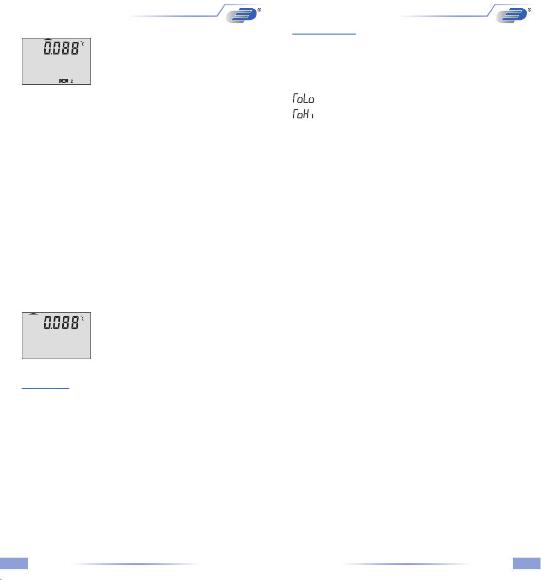
Exemple d’afchage de valeurs de mesure en mode Filter:
3. Messages d’erreur
Bei Fehlbedienungen oder Gerätestörungen unterstützt das Gerät den Bediener
durch folgende Fehlermeldungen:
En haut à gauche, au-dessus du 0, la èche indique que
l’instrument mesure en mode Filter.
Remarque:
Cette sélection est désactivée lorsque l’appareil est mis hors tension.
1.7 Fonction ARRÊT AUTO
dAoF = Disable Auto-off
EAoF = Enable Auto-off
Appuyez sur le bouton (ESC/AUTO-OFF). L‘écran afche lors dAoF. La fonction
Arrêt auto est maintenant désactivée. Lorsque vous appuyez de nouveau sur le
bouton (ESC/AUTO-OFF), EAoF apparaît sur l’écran. L’instrument de mesure
s’éteint automatiquement au bout de 30 minutes.
Remarque:
Cette sélection est désactivée lorsque l’appareil est mis hors tension (la sélection
par défaut est EAoF).
1.8 Fonction TARA (bouton ZERO F1)
L’instrument de mesure dispose d’une fonction TARA (fonction ZÉRO). Lorsque
vous utilisez cette fonction, la dernière valeur mesurée est soustraite de la
valeur actuelle et s‘afche comme nouvelle valeur. Appuyez une fois sur le
bouton [F1]. En appuyant de manière répétée sur le bouton (F1), vous accédez
de nouveau au mode normal.
Exemple d’afchage de valeurs de mesure en mode Zero:
En haut à gauche, la èche indique que l’instrument
est en mode TARA (F1).
Erreur Signication
oPEn Capteur non conforme ou non connecté
„too low“ Sous-dépassement de la plage de mesure
„too high“ Dépassement de la plage de mesure
E15 Pile entièrement déchargée
E19 Pile entièrement déchargée
E1d Pile entièrement déchargée
E16 Interruption de la fonction Arrêt auto (Rebrancher l‘appareil)
E1e Interruption de la fonction Arrêt auto (Rebrancher l‘appareil)
E23 Le contenu RAM a été détruit (vériez les paramètres)
E25 Contenu EE-prom endommagé
E31 Erreur d‘interface
LoLi la pile (CR2032) de sauvegarde interne est à plat (pour échanger la
pile il faut dévisser le boitier)
Remarque:
Des piles défectueuses ou vides peuvent causer des erreurs de mesure ou des
rapports d’erreur.
En cas de rapports d’erreur enlever les piles et attendre env. 3 minutes avant
d’insérer une nouvelle pile.
Remarque: Cette sélection est désactivée lorsque l’appareil est mis hors tension.
2. Alimentation
- L’appareil est alimenté par une pile de 9V. Pour remplacer la pile, mettez
l’appareil hors tension et ouvrez le compartiment à piles se trouvant au dos
de l’appareil. Retirez l’ancienne pile et insérez la nouvelle.
- L’icône de pile faible indique que la pile doit être remplacée sous peu. Vous
pouvez encore effectuer des mesures correctes pendant env. 1 heure.
- Le nombre de segments (jusqu’à 3) indique l’état de charge.
Attention:
Les vieux appareils électroniques et piles usagées ne doivent pas être jetées
avec les ordures ménagères. Dans le souci de protéger l‘environnement veuillez
les emmener dans un site approprié de récupération ou chez votre revendeur
selon les spécications nationales et locales.
2928
Page 16

3130
Page 17

DOSTMANN electronic GmbH
Mess- und Steuertechnik
Waldenbergweg 3b
D-97877 Wertheim-Reicholzheim
Germany
Phone: +49 (0) 93 42 / 3 08 90
Fax: +49 (0) 93 42 / 3 08 94
E-Mail: [email protected]
Internet: www.dostmann-electronic.de
Technische Änderungen vorbehalten ● Nachdruck auch auszugsweise untersagt
Stand01 1805CHB ● © DOSTMANN electronic GmbH
Technical changes, any errors and misprints reserved ● Reproduction is prohibited in whole or part
Stand01 1805CHB ● © DOSTMANN electronic GmbH
Tous droits réservés ● Toute reproduction est interdite
Stand01 1805CHB● © DOSTMANN electronic GmbH
 Loading...