

Dosmatic MiniDos 0.4, MiniDos 5, MiniDos 20, MiniDos 2.5, MiniDos 10 Operating Instructions Manual

®
Certified ISO 9001:2000 Quality Management System
MINIDOS
Installation & Operating Instructions
Model No.
MiniDos - 0.4%, 2.5%, 5%, 10%, 20%
1

CONTENTS:
CAUTION:
To reduce risk of injury, user must read and understand the Installation & Operation Instructions
before using this product.
ITEM PAGE
Introduction...........................................................................................................................................3
Safety.....................................................................................................................................................4
Installation..........................................................................................................................................5-7
Operation............................................................................................................................................8-9
Maintenance........................................................................................................................................10
Trouble Shooting.................................................................................................................................11
Repair Parts Motor..............................................................................................................................12
Specications.......................................................................................................................................13
Repair Parts Lower Ends................................................................................................................14-19
Wear Parts Kits...............................................................................................................................20-22
Warranty.........................................................................................................................................23-24
START UP PROCEDURES
SLOWLY turn on main water pressure until water ows between 5 & 12 gpm (11-45 lpm) or 30 psi
(2 bar) maximum to fully prime the suction hose.
SLOWLY open the water supply valve and all valves downstream of injector to release entrapped
air. Carefully open inlet valve allowing water to enter and pressurize the injector. Open outlet valve
and close bypass valve. Water will now ow through the injector, and a continuous sound will be
emitted from the injector as water passes through it. Check for system leaks (see page 5) and correct
if necessary. Adjust the outlet valves downstream from the injector, if necessary.
IMPORTANT:
FOR WARRANTY PURPOSES
VISIT OUR
WEB SITE
WWW.DOSMATIC.COM
TO FILL OUT PRODUCT
REGISTRATION FORM!
Part#013815 Rev E
English:2

QUICK TIPS:
To maintain a long service life for your MiniDos injector
1. Always cover solution container and keep it clean
2. Always use clean water
3. Always lter inlet water
4. Always keep solution lter (#27) 2” from bottom of container
5. Always stock main wear parts for lower end
Trouble-shooting your Dosmatic injector
Injectors should make a gentle clicking noise when in operation
If the unit is not clicking, contact your authorized Dosmatic repair distributor or return the unit to Dosmatic USA,
Inc
If the unit is clicking, but not pulling solution, please inspect the lower end of the injector (see
lower end diagrams) as follows:
Exterior Inspection
1. Inspect and clean lter (#27)
2. Inspect the suction tube (#25) for cracks. Replace suction tube if holes exist
3. If injector still does not pull solution, please proceed to steps 4-7
Cleaning the suction tube tting
4. Remove pin #79 and carefully pull out the inner cylinder (#37)
5. Unscrew the suction tube tting (#11) from the inner cylinder (#37)
6. Clean and rinse suction tube tting assembly (#11). Replace any damaged parts
7. If injector still does not pull solution, please proceed to steps 8-12
How to replace wear parts
8. Unscrew the external cylinder (#7), separating it from the body of the injector
9. Take hold of the shaft (#51) and turn it 90 degrees in any direction to release it.
Pull shaft from its housing
10. If you have the 0.4%, remove the dosage piston (#44) by unscrewing dosage piston support (#52) from
lower shaft assy (#51).
NOTE: Due to the delicate nature of the 0.4%, extra care should be taken to monitor dosage levels, verify
solution is free of debris, and to perform wear maintenance regularly.
If you have the 1% or 2.5%, remove the dosage piston (#44) by turning the lower shaft (#51) one quarter
turn and pull down.
If you have the 5% or 10%, remove the dosage piston (#44) by depressing the two “ears” of the shaft
(#52) simultaneously and removing the piston upwards. Replace dosage piston by sliding a new #44 from
top to bottom of the shaft until you hear a click.
If you have the 20%, remove the dosage piston (#44) by unscrewing the capscrew (#93) and remove the
dosage piston (#44) by pulling down.
Clean and inspect O-ring (#14).
The translucent openings (larger diameter/thinner lips) of the dosage piston should be on top.
11. Clean, dry and inspect inside the inner cylinder (#37 or #7 if 20%) from scratches or cracks. If damaged,
replace inner cylinder.
English:3

44
195008
195012 (2x)
195909
194309
010044
195444
190730
195200
195408
212005
195870
20% 011849
10% 011025
5% 011015
2.5% 010025
1% 010025
5% 011026
10% 011018
25
17
51
44
27
51
44
44
44
55
2.5% 011017
54
195871
195873
0.4% 011023
0.4% 003072
1% 011017
195950 95
93
51
44
2.5%
20%
10%
5%
1%
0.4%
INTRODUCTION:
Please take the time to read this instruction manual thoroughly and follow the procedures. This
will help increase the life of your injector.
Certain precautions, which are marked with this symbol need to be read carefully...
The injector is packaged with the following items: (shown in gure 1)
Dosmatic Injector (not shown)
Dosage Piston
O-ring
Manual (not shown)
Mounting Bracket
Mounting clips
Filter
Suction Tube
English:4
Fig.1
SAFETY:
1.SELECT A LOCATION: that is on the water line that chemical injection is desired and meets all
the following requirements as well as all applicable local codes.
Remove Red Caps Prior to Installation.
NOTE: The entire water line down stream from the injector will have chemical injected into it. If
the chemical injected makes the water unsafe to drink, label the water lines.
WARNING NOT FOR HUMAN CONSUMPTION!
2. AN APPROVED BACK FLOW PREVENTOR MUST BE INSTALLED, in the water
line ahead of the unit to prevent water and chemical mixture from entering the source water supply.
3. AVOID A POTENTIALLY HAZARDOUS CHEMICAL ACCIDENT: An injector loca-
tion should be selected to provide a safe, but accessible, place for the chemical solution container. It
should be kept away from children and/or high usage areas.
4. AVOID SOLUTION CONTAMINATION, use only clean FILTERED water. Do not allow
contaminants to enter the solution container because they will be pumped into the water line, and
can cause the spread of disease and can also cause excessive wear.
5. WATER TEMPERATURE
Max: 100°F or 38°C
Min: 32°F or 0°C
6. MAX WATER PRESSURE
10% & 20% - 65 PSI/4,5 BAR
0.4% - 5% - 140 PSI/9,7 BAR
7. RELEASE WATER PRESSURE, before working on injector
English:5

INSTALLATION:
1.NOTE: Water going through injector must be free of sand, dirt and grit. Installation of 140 mesh
(104 micron) or ner lter will be required.
2. MOUNT INJECTOR: Securely to a solid object such as a wall. Note arrow on injector indicat-
ing water ow. See g. 4.
3. BACKFLOW PREVENTOR: Install one adequately sized that meets your local code require-
ments.
4. BYPASS VALVE: To bypass injector when not in service or to service injector pipe in the three
valve bypass arrangement as shown in Fig. 3
5. CHECK SYSTEM FOR LEAKS: Open the bypass valve (A), close valves (B) and (C) so that
the water will not ow into injector SLOWLY turn on the main water line so that water will
run through the plumbing system. Turn on all of the valves located downstream from your injector
to release trapped air. Slowly turn on the inlet valve (B). Open the outlet valve (C) at injector outlet.
Close (A). As water travels freely through your injector, you will hear a soft “clicking” sound.
6. SOLUTION CONTAINER: Refer to gure 5. You may use any size container but we recom-
mend using one with a lid or cover. To connect your solution container gently push the end of the
suction tube (#25) onto the bottom of the tting assembly (#11). Place the lter into the solution
container at least 2 inches (5cm) from the bottom. Cover the solution lter with at least 2 inches.
(5cm) of chemical solution.
English:6

INSTALLATION DRAWINGS:
50mm
2" Required
Solution Filter
Bypass Valve (Required)
Outlet Valve (Required)
Inlet Valve (Required)
Inlet Filter (Required)
Suction Tube
Covered Container
TYPICAL INSTALLATION
(A)
Fig.3
(B)
(C)
English:7

50mm
2" Required
Covered Container
Inlet Filter (Required)
Inlet Valve (Required)
Bypass Valve (Required)
Outlet Valve (Required)
Suction Tube
Solution Filter
10 Feet (3 Meters)
Minimum Water Level
195008 Bracket
195012 Clip(2)
INSTALLATION DRAWINGS:
TYPICAL WALL MOUNTING
Fig.4
TANK FEED INSTALLATION
English:8
Fig.5

OPERATION:
Run Position
Increase
On/Off Lever
Decrease
Setting Indicator
Mark
SERVICE FLOW: Water drawn down stream from the injector will automatically cause the injec-
tor to “click” and inject the set amount of solution into the water line. The higher the ow rate the
more frequent the clicking, as the injector is designed to inject solution at the same set ratio regardless of water ow.
Water ow and pressure must be within the established specications. See the specication section
on page 10 for your model.
CHANGE FEED RATE: The feed rate on the injector is adjustable EVEN WHILE OPERATING
AND UNDER PRESSURE. Rotate the “Ratio Adjustment Sleeve” (#61) Important: for the 20%
model rotate the #7 Ratio Adjuster, to change the solution injection ratio. See g. 5,. The setting
indicator mark indicates the approximate ratio of injection setting. Check outlet water for chemical
to assure desired feed rate is being delivered.
NOTE: Do not rotate Ratio Adjuster below lowest setting line on decal. This can cause the injector
to lock.
BYPASS OPERATION: Injecting solution into the water line can be TEMPORARILY stopped
with the optional on/off feature. Moving the “On/off Lever” to the “OFF” position allows service
water to pass through the injector without injecting chemical. With the on/off lever set to the “ON”
position the injector will operate as normal and “clicking” will be heard when water is owing. It
is recommended to use the three valve bypass in Fig. 3, for continued bypassing or servicing of the
injector.
Fig.6
Example ratio sleeve
English:9

MAINTENANCE:
RINSE INJECTOR AFTER EACH USE, additive allowed to remain in injector can dry out
and damage lower end at the next start up. Put suction tube into a 1 qt. (4 liters) or more con-
tainer of fresh ltered water. Pull fresh water through the injector by operating until container is
empty. This procedure is not needed for continuous operation.
BYPASS INJECTOR: When not in use put the injector in bypass mode by using the three valve
bypass (preferred) or the optional on/off lever on the injector.
CLEAN SUCTION TUBE FILTER SCREEN: Inspect each time new solution is added. Clean
as frequently as necessary by washing in fresh water. Remove lter screen (#27) from suction tube
(#25) and run water backwards through it. Replace if necessary. Keep lter screen off bottom of
solution container to prevent dirt and precipitate from contaminating solution.
STORAGE: For extended storage, rinse injector as described above and place entire injector
underwater (in 5 gal container). Monthly, apply a small amount (thimble full) of chlorine bleach to
avoid algae growth.
CLEAN SOLUTION CONTAINER: Keep covered to prevent any contaminants from entering
container. Rinse container thoroughly and often. Do not mix chemicals together that might react
and cause a precipitate. Use FILTERED WATER when lling container.
CLEAN INLET FILTER: Clean or replace inlet lter as required to increase the life of the unit
as well as reduce pressure loss.
REPLACE DOSAGE PISTON AND SHAFT SEAL: The injector is shipped with a spare Dos-
age Piston (44) and shaft seal (17), see Fig. 1, as these are normal wear parts, replace both when
solution injection is less than set amount.
English:10

TROUBLE SHOOTING:
NO CLICKING SOUND
1. Water ow rate exceeds rated service ow of injector: Reduce ow rate (See Specications
Pg. 10).
2. Operating pressure exceeds maximum limit: Install a pressure reducer valve (See Specica-
tions Pg. 10).
3. #17 o-ring if leaking: Replace.
4. Main piston assembly #9 worn: Replace #9 and install a 104 micron lter before injector to
remove abrasive particles from water.
5. Cover #1 or main body #40 bores worn or scored: Lightly sand inside diameter of bores to
remove scoring grooves. Install a 104 micron lter to remove abrasive particles from water.
6. Poppets (Upper or Lower) are off poppet arms:
ow and/or pressure.
CLICKING SOUND WITHOUT SUCTION OF SOLUTION
1. Dosage piston #44 and o-ring retainer #15 are installed incorrectly: Be sure #44 dosage
piston is installed thin lips up.
2. Dosage piston #44 worn: Replace as necessary.
3. O-ring seat #14 or dosage piston #44 damaged: Replace as necessary.
4. #7 cylinder is worn or scored: Replace
5. #17 o-ring is worn and/or loose: Replace
6. Suction tube #25 or suction tube tting #11 cracked & leaking: Replace as necessary
7. Clogged suction tube lter: Replace and/or clean as necessary.
Replace all poppet assemblies and reduce
8. Check valve #13 leaking: Clean & replace as necessary.
WATER RE-FILLING SOLUTION TANK
1. Check valve #13 leaking: Check seat area on suction tube tting #11. Check valve and seal
must t loose in the suction tube tting.
2. Washer seal on #13 is swollen: Replace with new check valve assembly.
English:11
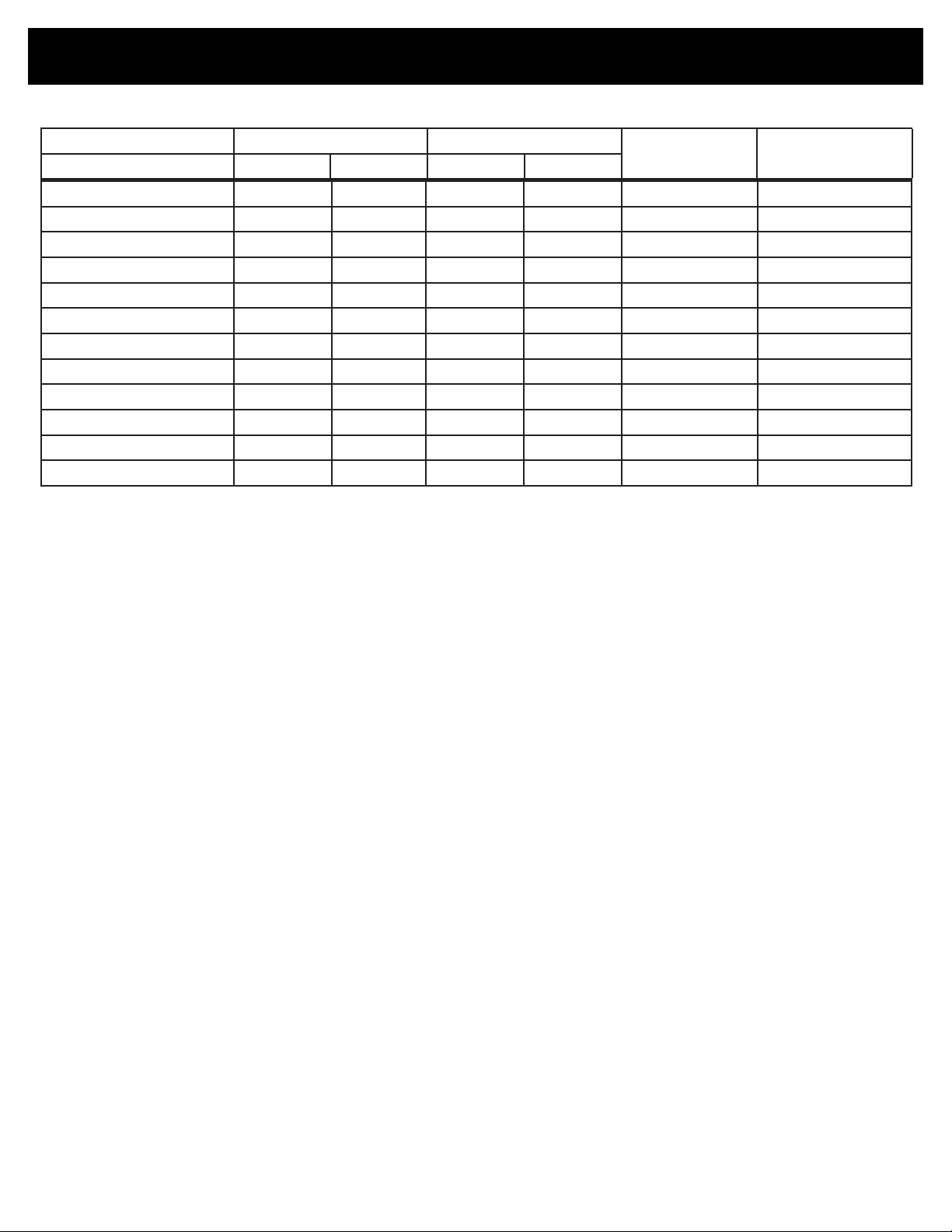
SPECIFICATIONS:
Model Flow Rate Feed Ratio
Minimum Maximum Minimum Maximum
MiniDos 0.4% 0.03 gpm 12 gpm 0.025% 0.40% 6 – 140 psi ¾” npt
0,11 lpm 45,42 lpm 1:4000 1:250 0,41 – 9,7 bar ¾” bsp
MiniDos 1% 0.03 gpm 12 gpm 0.20% 1.00% 6 – 140 psi ¾” npt
0,11 lpm 45,42 lpm 1:500 1:100 0,41 – 9,7 bar ¾” bsp
MiniDos 2.5% 0.03 gpm 12 gpm 0.50% 2.50% 6 – 140 psi ¾” npt
0,11 lpm 45,42 lpm 1:200 1:40 0,41 – 9,7 bar ¾” bsp
MiniDos 5% 0.03 gpm 12 gpm 1.00% 5.00% 6 – 140 psi ¾” npt
0,11 lpm 45,42 lpm 1:100 1:20 0,41 – 9,7 bar ¾” bsp
MiniDos 10% 0.07 gpm 10 gpm 2.0% 10.0% 6 – 65 psi ¾” npt
0.25 lpm 37,85 lpm 1:50 1:10 0,41 – 4,5 bar ¾” bsp
MiniDos 20% 0.07 gpm 7 gpm 4.00% 20.00% 6 - 65 psi ¾” npt
0.25 lpm 27 lpm 1:25 1:5 0,41 - 4,5 bar ¾” bsp
Operating
Pressure
Inlet/Outlet
Pipe Connection
English:12
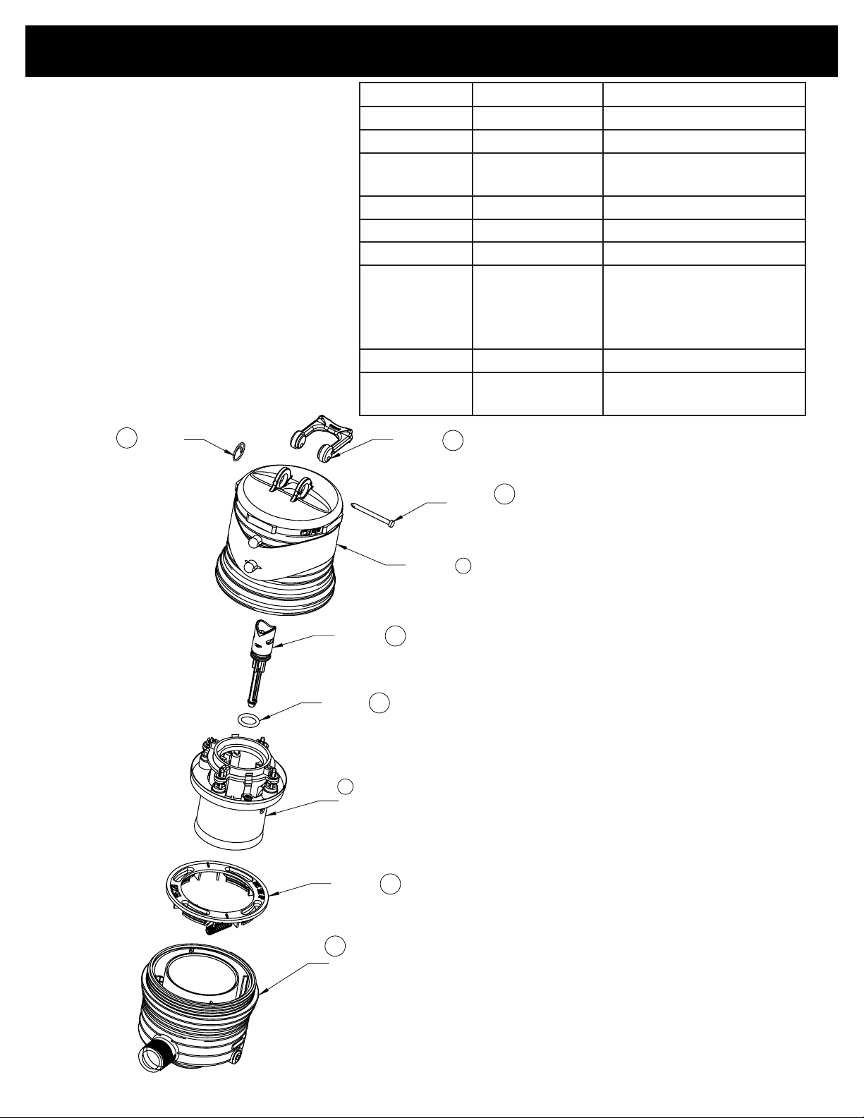
REPAIR PARTS:
87
34
1
9
86
40
20
85
21
195914 (Heavy Duty Pin)
193641
195910
190100
195912
195700
011662UP 20%
011666
195720
011011 20% BSP Threads
Ordering Information
011012 NPT Threads
011013 BSP Threads
011010 20% NPT Threads
212009
(2x for Heavy Duty)
Reference # Part # Description
1 190100 Upper Body
87 195910 On/Off Handle
85
195912
195914
34 193641 Cotter Ring
21 195700 Shaft
20 212009V O-ring
011012
40
011013
011010 20%
011011 20%
86 195720 Mixing Chamber Gasket
9
011666
011662UP 20%
Upper Shaft Pin
Heavy duty upper shaft pin
Lower Body NPT
Lower Body BSP
Piston Assembly
English:13

LOWER END INJECTOR & WEAR PARTS KITS 0.4%:
Kit A - Wear Parts Kit (dosage piston/lower shaft assy,
and oring)
Kit C - Wear Parts Kit (Kit A, inner cylinder and oring) 011110 12, 14, 37, 44, 52
Kit D - Suction Tube Fitting Assy ( poppet, oring, tting,
spring)
Kit E - Wear Parts Kit (Kits C & D, upper shaft, pin) 011112 10, 11, 12, 13, 14, 37, 44, 51, 52,
Kit G - Lower End Kit, complete (Kit E, outer cylinder,
ratio adjuster, orings, clips, pins, retainer, lter, solution
tube)
Kit H - Motor Piston Assy (upper end kit) 011662S 9
Kit Hby - Remote Injection Kit 011762 (Viton) 32
Kit M - Mounting Bracket Kit (mounting bracket, 2 pins) 011732 54, 55
Manual Reference Part # Description of Part
7 190031 MiniDos Outer Cylinder
10 195875 MiniDos 0.4% Spring
11 193201 Suction Tube Fitting
12 212120
*Must specify material
13 011453A Check Poppet
14 212008
*Must specify material
16 195709 Seal
17 212005
*Must specify material
25 011023 Suction Tube 1/8" x 3'
27 003072 Filter for suction tube 1/8"
37 195876 MiniDos 0.4% Inner Cylinder
44 195873 MiniDos 0.4% Dosage Piston
51 011009 MiniDos 0.4% Upper Shaft Assy
52 195871 MiniDos 0.4% Piston Support
60 212517W O-ring
61 195874 MiniDos 0.4% Ratio Adjuster
79 195224 Interlock Pin
82 195740 Shaft seal spacer
91 193054 Seal, check valve
92 193854 Hose Nut 1/8"
Oring
Oring
O-ring
011109 14, 44, 52
011111 10, 11, 13, 91
79, 91
011113 7, 10, 11, 12, 13, 14, 16, 17, 25,
27, 37, 44, 51, 52, 60, 61, 79, 91,
92
011764 (EPDM)
English:14
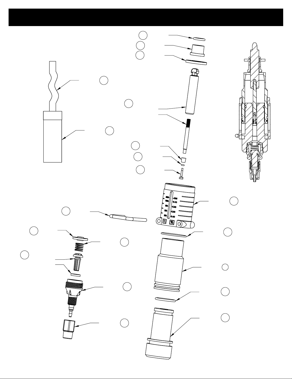
LOWER END INJECTOR PARTS 0.4%:
17
195709
195873
195871
190031
195876
195224
212517
212120
212008
195874
25
190727
195870
011009
212005
19574082
91
011453
27
79
10
11
13
16
52
51
44
14
61
60
12
37
92
194413
193054
195875
194416
193201
193854
003072
011023
7
English:15

LOWER END INJECTOR & WEAR PARTS KITS 1%:
Description of Kit Part # Manual Reference
Kit A – Wear Parts Kit (dosage piston, oring) 011071 14, 44, 51
Kit C – Wear Parts Kit (Kit A, inner cylinder, oring) 011072 12, 14, 44, 51, 63, 68
Kit D – Suction Tube Fitting Assy (poppet, nut, washer,
oring, spring, tting)
Kit E – Wear Parts Kit (Kits C & D, upper shaft, pin) 011073 10, 11, 12, 13, 14, 44, 51, 52,
Kit G – Lower End Cylinder Kit (Kit E, outer cylinder,
ratio adjuster, oring, clip, pin, retainer, lter, solution tube)
Kit H – Motor Piston Assy (upper end kit) 011662S 9
Kit Hby - Remote Injection Kit 011762 (Viton)
Kit M – Mounting Bracket Kit (mounting bracket, 4 hex
caps & nuts)
Manual Reference Part # Description of Part
7 190011 Cylinder,outer
10 194418H Spring
11 194417 Fitting, suction tube, ¼”
12 212120
*Must specify material
13 011453A Poppet, check w/washer
14 212022
*Must specify material
16 195709 Gasket
17 212005
*Must specify material
25 010025 Suction tube, ¼” x 5’
26 195761 Anti Lock Gasket
27 011017 Filter for suction tube, ¼” ID
37 195405 Inner Cylinder
44 195200 Dosage Piston
51 190730 Shaft, lower
52 190030 Shaft, upper
60 212517W O-ring
61 195426 Ratio adjustment sleeve
63 212516
*Must specify material
68 190750 Cylinder, inner for #7
71 194414 Nut, suction tube tting
79 195224 Pin, narrow interlock
80 194415 Twistlock
82 195740 Shaft seal spacer
011046 10, 11, 12, 13, 71, 80
63, 68, 71, 80, 79
011068 7, 10, 11, 12, 13, 14, 16, 17, 25,
26, 27, 37, 44, 51, 52, 60, 61,
63, 68, 71, 79, 80, 82
32
011764 (EPDM)
011732 54, 55
O-ring
O-ring
O-ring
O-ring, inner cylinder
English:16

LOWER END INJECTOR PARTS 1%:
68
011453
79
13
17
82
16
52
44
14
51
60
7
12
26
37
61
010025
011017
71
195740
195709
190030
195200
190730
195426
190011
195761
195405
190750
195224
212005
212022
212517
212120
25
27
12
80
10
11
21251663
194418
194415
194413
194417
194416
194414
212120
English:17

LOWER END INJECTOR & WEAR PARTS KITS 2.5%:
Description of Kit Part # Manual Reference
Kit A – Wear Parts Kit (dosage piston, oring) 011055 17, 44
Kit B – Wear Parts Kit (Kit A, lower shaft, oring) 011044 14, 17, 44, 51
Kit C – Wear Parts Kit (Kit A, inner cylinder, oring) 011045 12, 17, 37, 44
Kit D – Suction Tube Fitting Assy (poppet, nut, washer, oring, spring,
tting)
Kit G - Lower End Kit, complete (Kit D, outer cylinder, ratio adjuster,
oring, retainer clip, pin, retainer, lter, solution tube)
Kit H – Motor Piston Assy (upper end kit) 011662S 9
Kit Hby - Remote Injection Kit 011762 (Viton)
Kit M – Mounting Bracket Kit (mounting bracket, 4 hex caps & nuts) 011732 54, 55
Manual Reference Part # Description of Part
7 190011 Cylinder, outer
10 194418H Spring
11 194417 Fitting, suction tube, ¼”
12 212120
*Must specify material
13 011453A Poppet, check w/washer
14 212501
*Must specify material
16 195709 Gasket
17 212005
*Must specify material
25 010025 Suction tube, ¼” x 5’
O-ring
O-ring
O-ring
26 195760 Anti Lock Gasket
27 011017 Filter and foot valve, suction tube, ¼” ID
37 195404 Inner Cylinder
44 195444P Dosage Piston
51 195408 Shaft, lower
52 195727 Shaft, upper
60 212517W O-ring
61 195430 Ratio adjustment sleeve
71 194414 Nut, suction tube tting
79 195224 Pin, narrow interlock
80 194415 Twistlock
82 195740 Shaft seal spacer
011057 10, 11, 12, 13, 71, 80
011047 7, 10, 11, 12, 13, 14,
16, 17, 25, 26, 27,
37, 44, 51, 52, 60,
61, 71, 79, 80, 82
32
011764 (EPDM)
English:18

LOWER END INJECTOR PARTS 2.5%:
010025
011017
194418
194415
194413
194417
194414
194416
212120
80
27
79
17
82
16
52
44
14
51
61
7
60
12
26
37
11
71
13
10
12
195709
195740
195727
195444
195408
195224
195430
190011
195404
195760
212005
212501
212517
212120
25
011453
English:19

LOWER END INJECTOR & WEAR PARTS KITS 5%:
Description of Kit Part # Manual Reference
Kit A – Wear Parts Kit (dosage piston, oring)
Kit B – Wear Parts Kit (Kit A, shaft)
Kit C – Wear Parts Kit (Kit A, inner cylinder, oring)
Kit D – Suction Tube Fitting Assy (poppet, nut, washer, oring, spring, t-
ting)
Kit E – Wear Parts Kit (Kits C & D, inner cylinder (2nd inner cylinder),
shaft, pin, gasket)
Kit G - Lower End Kit, complete (Kit E, outer cylinder, ratio adjuster, oring,
retainer clip, pin, retainer, lter, solution tube)
Kit H – Motor Piston Assy (upper end kit)
Kit Hby – Remote Injection Kit 011762 (Viton)
Kit M – Mounting Bracket Kit (mounting bracket, 4 hex caps & nuts) 011732 54, 55
Manual Reference Part # Description of Part
7 190031 Cylinder, outer
10 194418H Spring
11 194412 Fitting, suction tube, 3/8”
12 212120
*Must specify material
13 011453A Poppet, check w/washer
14 212005
*Must specify material
16 195709 Gasket
17 212005
*Must specify material
25 011015 Suction tube, 3/8” x 5’
O-ring
O-ring
O-ring
26 195761 Anti Lock Gasket
27 011026 Filter and foot valve, suction tube, 3/8” ID
37 195405 Inner Cylinder
44 010044P Dosage Piston
52 195726 Shaft, upper
60 212517W O-ring
61 195428 Ratio adjustment sleeve
71 194414 Nut, suction tube tting
79 195224 Pin, narrow interlock
80 194415 Twistlock
82 195740 Shaft seal spacer
011076 17, 44
011077 17, 44, 52
011074 12, 17, 37, 44
011079 10, 11, 12, 13, 71,
80
011080 10, 11, 12, 13, 17,
37, 44, 52, 71,
79, 80
011081 7, 10, 11, 12, 13,
14, 16, 17, 25, 26,
27, 37, 44, 52, 60,
61, 71, 79, 80, 82
011662S 9
32
011764 (EPDM)
English:20

LOWER END INJECTOR PARTS 5%:
011015
011026
79
011453
17
82
16
44
14
52
61
26
7
60
12
37
13
194413
194415
194418
194412
194414
194416
212120
11
195740
195709
010044
195726
195428
195761
190031
195405
195224
212005
212005
212517
25
27
12
80
10
212120
71
English:21

LOWER END INJECTOR & WEAR PARTS KITS 10%:
Description of Kit Part # Manual Reference
Kit A – Wear Parts Kit (dosage piston/shaft assy, oring)
Kit B – Wear Parts Kit (Kit A, shaft)
Kit C – Wear Parts Kit (Kit A, inner cylinder, oring)
Kit D – Suction Tube Fitting Assy (poppet, nut, washer, oring, spring, tting)
Kit E – Wear Parts Kit (Kits C & D, inner cylinder (2nd inner cylinder), shaft,
pin, gasket)
Kit G - Lower End Kit, complete (Kit E, outer cylinder, ratio adjuster, oring,
retainer clip, pin, retainer, lter, solution tube)
Kit H – Motor Piston Assy (upper end kit)
Kit Hby – Remote Injection Kit 011762 (Viton)
Kit M – Mounting Bracket Kit (mounting bracket, 4 hex caps & nuts) 011732 54, 55
Manual Reference Part # Description of Part
7 195790 Outer cylinder
10 194418H Spring
11 011452 Fitting, suction tube
12 212120
*Must specify material
13 011453A Poppet, check w/washer
14 212005
*Must specify material
15 194004 Seal retainer, o-ring
16 010016S Gasket, inlet/outlet and cylinder
17 212005
*Must specify material
25 011025 Suction tube, 1/2” x 5’
27 011018 Filter and foot valve, suction tube, 1/2” ID
37 194405P Inner Cylinder
44 194309 Dosage Piston
52 195729 Shaft
61 194406P Ratio adjustment sleeve
64 212017
*Must specify material
65 194310D Pin, upper interlock
66 212025
*Must specify material
71 194414 Nut, suction tube tting
77 003039 Hose Barb 1/2" x 3/8"
79 194410SS Pin, narrow interlock
80 194415 Twistlock
83 190741 Shaft seal spacer
O-ring
O-ring
O-ring
O-ring, inner cylinder, lower end
O-ring, outer cylinder, lower end
English:22
011082 17, 44
011083 17, 44, 52
011084 17, 37, 44, 64
011085 10, 11, 12, 13, 71,
77, 80
011087 10, 11, 13, 17, 37,
44, 52, 64, 65, 71,
77, 79, 80
011088 7, 10, 11, 12, 13,
14, 15, 16, 17, 25,
27, 37, 44, 52, 61,
64, 65, 66, 71, 77,
79, 80, 83
011662S 9
32
011764 (EPDM)

LOWER END INJECTOR PARTS 10%:
212017
194004
190741
010016
194309
195729
195790
194406
194405
194410
25
194310
27
212005
212005
212025
71
011453
17
83
14
52
7
64
61
66
37
65
79
12
80
13
10
11
77
194418
194415
194413
194416
194414
003039
011452
212120
011025
011018
15
16
44
English:23
LOWER END INJECTOR & WEAR PARTS KITS 20%:
Description of Kit Part # Manual Reference
Kit A – Wear Parts Kit (dosage piston, o-rings)
Kit B – Hose Kit
Kit C – Wear Parts Kit (Kit A, o-rings)
Kit H – Motor Piston Assy (upper end kit, excluding knob & shaft)
Kit M – Mounting Bracket Kit (mounting bracket, 4 hex caps & nuts)
Manual Reference Part # Description of Part
7 011913P Ratio adjuster
15 194004 Seal retainer, o-ring
17 212005
*Must specify material
44 195909 Dosage Piston
45 212006
*Must specify material
51 011904 Shaft, upper
53 194344 Klipring
60 011849M Hose Kit
61 195851 Outer Cylinder
66 212228
*Must specify material
68 212002
*Must specify material
72 195850 Adapter
73 195855 Dosage Piston Guide
79 195911 Ratio Locking Pin
83 190741 Shaft seal spacer
91 212518
*Must specify material
92 195861 Shaft Cap
93 193003 Capscrew 10-32 x 1/2" SS Hex Head
94 212004
*Must specify material
O-ring
Oring, Adapter, Dosage Piston Guide
O-ring, outer cylinder, lower end
O-ring, Adapter, Lower Housing
Oring, Dosage Piston Guide
Oring, Ratio Adjuster
011105 17, 44, 45
011849M 60
011106 7, 17, 44, 45, 66,
68, 94
011662UPS 9
011732 54, 55
English:24

LOWER END INJECTOR PARTS 20%:
61
60
51
17
53
83
15
68
72
44
45
73
91
92
93
7
94
66
79
011849M (Kit)
212004
194344
194343
194342
195860
190741
194004
195850
195855
195861
193003
011913P
195911
195851
195909
011904
212010
212005
212002
212006
212518
212228
English:25

WARRANTY:
The Dosmatic Warranty
We believe that we make the best and most reliable water-driven injectors available. Therefore, our war-
ranty reects our condence. We will back our units with the best guarantee available.
Dosmatic will provide for replacement of all parts proven to be defective in material or workmanship from
the date of purchase for the following time periods:
3 years - The cover and body are warranted to be free from defects in materials and workmanship for
THREE YEARS from date of purchase, or we’ll replace them free of charge.
2 years - The water motor is warranted to be free from defects in materials and workmanship for
TWO YEARS from date of purchase, or we’ll replace it free of charge.
1 year - The lower end (chemical pump) is guaranteed for ONE YEAR, or we’ll replace it free of charge.
Your only responsibility is ordinary maintenance.
*Note: (Your only responsibility is ordinary maintenance - ltering incoming water and solution and replacing the o-ring and dosage piston when worn).
Return the unit to the distributor or to Dosmatic’s manufacturing facility, freight prepaid. Upon inspection,
the unit will be repaired or replaced at Dosmatic’s option free of charge, if found to be defective in material
or workmanship and will be returned freight prepaid.
This warranty only covers circumstances where the part has failed due to defects caused by the manufac-
turing process. This warranty is not valid if the defects are found to be due to the product’s misuse, lack of
maintenance, defective installation, freezing, water hammer, misuse or abuse or unwanted side effects due
to the chemicals you choose to inject. Possible warranty issues may arise if injector body is disassembled.
If you suspect you are having a problem in the motor piston assembly or inside the body please contact
Dosmatic or any accredited warranty station to arrange to send the injector in to be evaluated and/or repaired. Before using any aggressive chemicals, please visit www.dosmatic.com to conrm chemical com-
patibility or contact your nearest distributor.
There is no warranty expressed or implied relating in any way to products used in conjunction with Dosmatic USA/International, Inc. products.
Dosmatic or authorized distributor shall no be liable for incidental or consequential damage, such as any
economic loss, resulting from breach of this written warranty or implied warranty. There are no warranties,
expressed or implied, which extend beyond those described above.
English:26

WARRANTY & LOCATIONS:
Dosmatic Europe S.A.R.L.
20 Route de Taillefer
33450 Montussan
(Bordeaux) France
Tel: +33 (0) 5 57 97 13 13
Fax: +33 (0) 5 57 97 10 19
Email: info@dosmatic-europe.com
Dosmatic Australia~New Zealand
P.O. Box 9074
Wyoming, NSW 2250 Australia
Tel: +61 (0) 2 43 29 09 05
Fax: +61 (0) 2 43 29 09 04
Mb: (61) 418 607 156
Email: doug.rowe@dosmatic-anz.com.au
Dosmatic Japan
Kakamigahara City,504 Japan
Tel: +81 (0) 583 83 0505
--
Fax: +81 (0) 583 83 1230
Email: hytem@mx2.ne.jp
Dosmatic Asia Co., Ltd.
861/8 T.I.T. Tower Rm. 1703
Satupradit Rd.
Bangkok, Thailand 10120
Tel: +66 (0) 26 74 97 58
Fax: +66 (0) 26 74 97 59
Email: infor@dosmaticasia.com
Lerenveld 14
Lint 2547 Belgium
Tel: +32 3 488 7371
Fax: +32 3 488 0227
Email: jozef.stolck@dosmatic-benelux.be
Dosmatic Latin America
Tel: +54 11 4115 1235
Fax: +54 11 4115 1481
Email: gpadin@dosmaticla.com.ar
Dosmatic Benelux
Loria 398 , 4º Piso Of. 16
Lomas De Zamora
CP B1832 IXH
Provincia de Buenos Aires , Argentina
2-10 Techno Plaza
Dosmatic U.S.A./International, Inc.
1230 Crowley Circle
Carrollton, TX USA 75006
Tel: (972) 245-9765
+1 (800) 344-6767 (USA & Canada)
Email: info@dosmatic.com
Fax: (972) 245-9000
www.dosmatic.com
To return a unit for repair:
1. Thoroughly rinse all chemical solution from the lower end of the unit.
2. Drain the water from the upper end of the injector, leaving a small amount so that the seals do not dry out.
3. If possible, identify the chemical solution injected and include a copy of the chemical manufacturer’s Material
Safety Data Sheet for each chemical injected.
4. All claims for warranty repair must include a copy of the original invoice listing the serial number of the injector
to be repaired.
5. With each injector returned, please ll out the return form in this manual.
6. If returning to Dosmatic, ship to:
Dosmatic U.S.A.
1230 Crowley Circle
Carrollton, TX 75006
7. For the name of your nearest Service Center, call us toll free at (800) 344-6767 or at (972) 245-9765.
8. There are no warranties which extend beyond those described above.
English:27
 Loading...