


PRODUCT REGISTRATION
20195 S. DIAMOND LAKE RD, STE 100 • ROGERS, MN 55374 • TOLL-FREE: 800.822.0295 • FAX: 763.428.4821
SAFETY, OPERATION, AND PARTS MANUAL
PRODUCT REGISTRATION
Single Disk Chipper
Model No.______________ Serial No. ___________________________
(Serial Number Location: Stamped in Frame, Near the Engine)
Engine Make: ____________________________________
Model No.: _________________ Serial No.: __________________
Clutch Make: _____________________________________
Model No.: _________________ Serial No.: __________________
CUSTOMER INFORMATION:
Name: ______________________________________________________________________________
Address: ____________________________________________________________________________
City:_______________________________State:______Zip:________Phone No.:_________ _________
Signature/Title: _______________________________________________________________________
❑ Yes, I have received my ❑ Chipper Manual, ❑ Knife Gage, ❑ Engine Manual, and ❑ Clutch Manual.
❑ Yes, I have been instructed on the operating and safety procedures of this machine.
DEALER INFORMATION:
Dealer: ______________________________________________________________________________
Address: ____________________________________________________________________________
City:_______________________________State:______Zip:________Phone No.:_________ _________
Signature/Title: _________________________________________Delivery Date:__________________
❑ Yes, I have inspected and prepped this machine for delivery.
Please Complete This Registration Form and Return It To Dosko.
Dosko
REV. 9/99 PAGE 1 D OSKO

TABLE OF CONTENTS
20195 S. DIAMOND LAKE RD, STE 100 • ROGERS, MN 55374 • TOLL-FREE: 800.822.0295 • FAX: 763.428.4821
Model 510 SD - Kubota
PRODUCT REGISTRATION .............................. 1
For Your Records - 3 Part NCR Paper You Must
Complete and Return Top White Copy To Dosko
within 10 days for your warranty to be valid.
TABLE OF CONTENTS ....................................... 2
INTRODUCTION
a. Message To Operator ................................... 3
b. Receiving Your Dosko Unit ......................... 4
c. Pre-Operating Check List ............................ 5
EQUIPMENT
a. Component Identification ............................ 6
b. Dimensions .................................................. 7
c. Specifications ............................................8-9
a. Opening Swing Away Feed Roll Assy ....... 26
b. Knives, Knife Care..................................... 27
c. Knife System .............................................. 28
d. Adjusting Bed Knife .................................. 29
e. Sharpen Feed Roller Blades ...................... 30
f. Changing Knife Holder/Fan Blade ............ 31
g. Closing Chipper Body ............................... 32
h. Adjust Chipper Belt Tension ..................... 33
i. Adjust Hydraulic Pump Belt Tension ........ 34
j. Belt and Sheave Care ................................. 35
k. Sheave Installation and Alignment ............ 36
l. Bolt Torque Chart ...................................... 37
m. Trailer Wiring Diagram .............................. 38
n. Hydraulics .................................................. 39
o. Trouble Shooting Hydraulics ................ 40-43
p. S
q. S
r. S
MART FEED ............................................... 44
MART FEED (Wiring Diagram)................. 45
MART FEED (Trouble Shooting) ............... 46
SAFETY
a. Definitions .................................................. 10
b. Sticker List ................................................. 11
c. Sticker Identification ............................. 12-13
d. Sticker Locations ....................................... 14
SAFETY & OPERATION
a. Instructions To The Crew ...................... 15-16
b. Safe Working Area ..................................... 17
c. Operation and Adjustments ........................ 18
d. Towing Instructions............................... 19-21
OPERATION MAINTENANCE
a. Fuel & Hydraulic Tanks ............................. 22
b. Maintenance Schedule ............................... 23
c. Belt Inspection Cover ................................ 24
d. Lubrication ................................................. 25
MAINTENANCE
PARTS LIST AND ILLUSTRATIONS
a. Hydraulic Components .............................. 47
b. Pump Mount .............................................. 48
c. Main Frame ........................................... 49-50
d. Chipper Assembly ...................................... 51
e. Rotating Chipper Assembly ....................... 52
f. Upper Feed Roll Assembly ........................ 53
g. In-Feed Hopper .......................................... 54
h. Discharge Assembly................................... 55
LIMITED WARRANTY POLICY ..................... 56
(Engine Manual Are Separate Documents)
REV. 9/99 PAGE 2 D OSKO

INTRODUCTION
20195 S. DIAMOND LAKE RD, STE 100 • ROGERS, MN 55374 • TOLL-FREE: 800.822.0295 • FAX: 763.428.4821
MESSAGE TO OPERATOR
Upon receiving you new unit, it is always exciting to “get going” and see its performance!
The “operator”, however, is the key to everything!
Every operator should read this safety and operation manual to be sure of safety instructions and proper
operating procedure. If the owner of this unit is different than the operator, his reading this manual will not
protect the user. As with any mechanical equipment, this equipment is very safe if used with care and
precaution--and very dangerous if used carelessly.
Performance is relative to the operators knowledge
of how to use the equipment!
BE A GOOD OPERATOR...
BE A SAFE OPERATOR!
DOSKOCIL POLICY
Dosko, Inc., reserves the right to
make changes in engineering,
design, and specifi-cations; add
improvements; or discontinue
manufacture at any time without
notice or obligation. Dosko, Inc.,
also reserves the right to change
machine and part prices as needed
without advance notice.
REV. 9/99 PAGE 3 D OSKO

INTRODUCTION
20195 S. DIAMOND LAKE RD, STE 100 • ROGERS, MN 55374 • TOLL-FREE: 800.822.0295 • FAX: 763.428.4821
RECEIVING YOUR
DOSKO SINGLE DISK CHIPPER UNIT
Congratulations, You have just purchased the finest Chipper of it’s kind. Dosko wants to be sure that you have
received it in good condition.
Delivery By Dealer
Your Doskocil unit should have been delivered completely inspected, tested, assembled, and ready to operate!
Do Not take anything for granted! Read the “Pre-Operating Check List” on page 5 and verify that the unit has
been properly “Prepped” before use. The dealer is responsible for delivering the manuals to you, If you have
not received your manuals, DO NOT START the machine, but contact your dealer.
Direct Shipment To Customer:
Upon delivery, “and before the truck driver leaves your premises,” please check for any freight damages. If
freight damages have occurred let the driver know immediately. Have the driver write up a claim form and
contact this company’s claim adjustor to come out and assess the damages for payment to you. This is your
responsibility to notify the truck company’s of freight damages.
Freight damage is not covered under the Dosko warranty policy.
Some assembly may be be required! If so, instructions are included as a separate written flyer. Please read
these special assembly instructions carefully! Your Dosko Brush Chipper has been pre-run at the factory prior
to shipping. Upon receiving your Dosko Chipper, read and understand the complete safety and operational
instruction manual for your unit. Read the “pre-operating” check list on page 5 to properly “prep” your chipper
before using.
The owner’s manual is shipped next day registered air mail, to the customer when a chipper is shipped direct
from the factory. If you should have any questions regarding the safety or operational procedures contact
Dosko before using this chipper.
Factory Pick Up or Delivery:
In these cases, your unit has been completely assembled tested and pre-run. It should be ready for immediate
usage. You will pick up the manuals with the machine. Read and study your manuals.
REV. 9/99 PAGE 4 D OSKO

INTRODUCTION
20195 S. DIAMOND LAKE RD, STE 100 • ROGERS, MN 55374 • TOLL-FREE: 800.822.0295 • FAX: 763.428.4821
PRE-OPERATING CHECK LIST
This check list must be followed and verified before starting this new chipper.
Read chipper, engine, and clutch manuals.
Start with checking the Machine:
❑ All safety sticker in place according to page 14.
❑ Check for safety chain
❑ Check and set rear stabilizer stand and pin.
❑ Check function of jack stand and retainer.
❑ Check hitch and torque bolts.
❑ Check function of all tail lights, running, license,
Stop, Right turn, Left turn lights.
❑ Check condition of plug and cable.
❑ Check tires, lug nuts, pressure.
❑ Check fuel tank (min 1/4).
❑ Check hydraulic tank (oil on screen is full).
❑ Lube all left side bearings (chipper & feed
rollers).
❑ Open belt guard hood, check drive belt tension.
❑ Open battery box, check terminals.
❑ With Kubota engine, centrifugal clutch will
engage at 1,450 RPM. Listen for any foreign
metal to metal sounds. Identify all sounds!!
❑ Check all engine controls and function of gages.
Kubota engine at 3,000 rpm
check the following:
❑ Check feed control lever, pull to feed in, push to
stop, push farther to reverse feed.
❑ Check direction of feed roller rotation, when
control is pulled out, the feed should be in.
❑ Check function of speed control fast to slow, set
at approximately 150 fpm. Lock control lever.
❑ Check Smart Feed function:
reduce engine rpm to 2800, feed roller will stop
turning.
❑ Lube all right side bearings (clutch, chipper, and
feed rollers).
Open Chipper Body:
❑ Check both knives / bed knife clearance.
❑ Check bolt torque, knifes, bed knife, fan blades,
disks.
❑ Close body, re-bolt, be sure all bolts/nuts are
re-assembled and torqued.
Before starting the engine,
check the following:
❑ Check engine oil level.
❑ Check discharge clamp.
❑ Check deflector and control latch.
Plan position of discharge before test run.
Follow all safety rules, wear safety gear:
❑ Feed brush into chipper for approximately one
hour for break in period.
❑ Shut machine down; for complete inspection.
❑ Check engine gages, check belt tension, and
clutch engagement tension. Go through complete
chipper and check for loose nuts and bolts and
any possible hydraulic leaks.
510 30 Kubota
REV. 9/99 PAGE 5 D OSKO

EQUIPMENT
20195 S. DIAMOND LAKE RD, STE 100 • ROGERS, MN 55374 • TOLL-FREE: 800.822.0295 • FAX: 763.428.4821
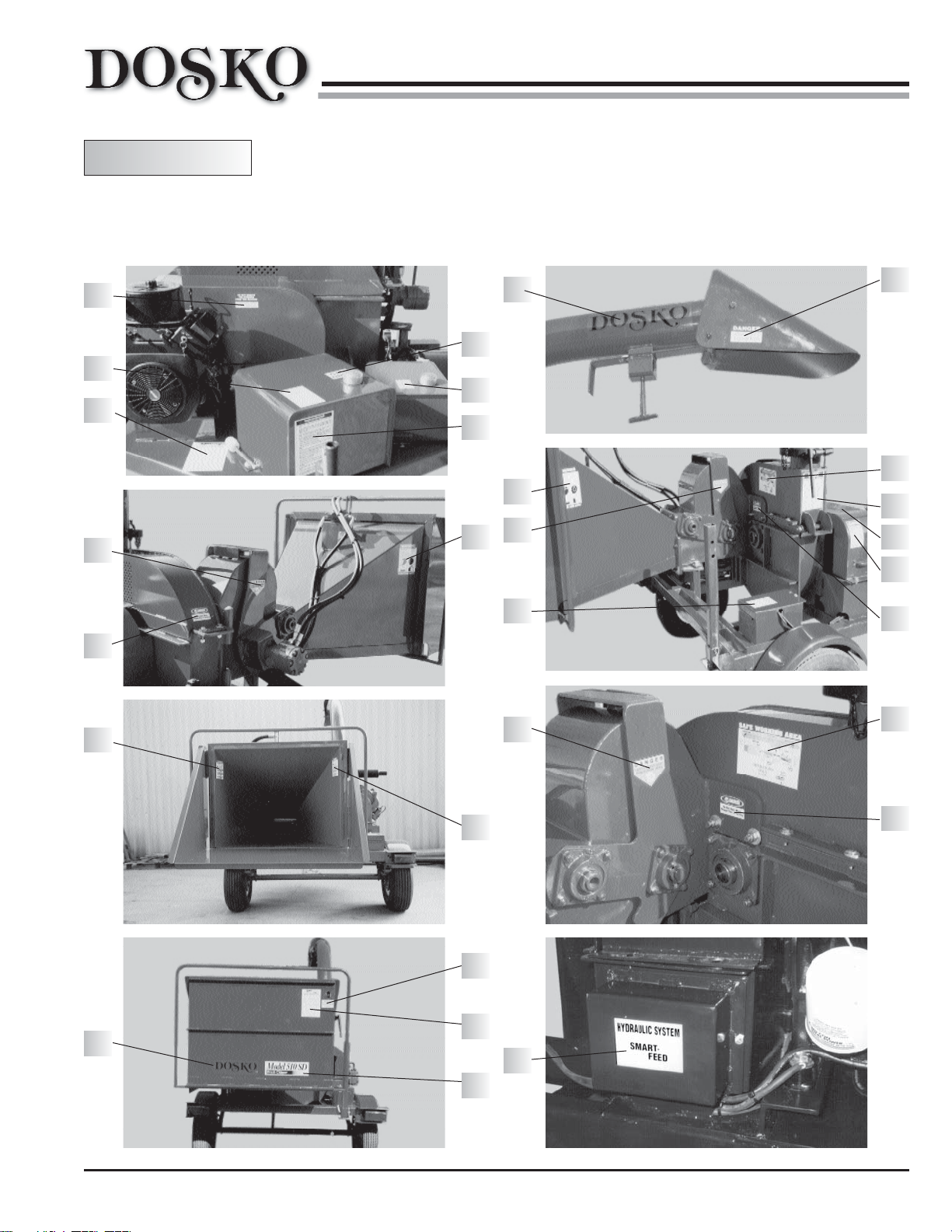
Model 510 SD
Rear Stabilizer
LEFT SIDE VIEW
COMPONENT IDENTIFICATION
Discharge Tube
360° Discharge
Swivel Ring
Deflector Angle Control
Smart Feed Fuse
RIGHT SIDE VIEW
Deflector
Engine
Hitch
Jack Stand
In Feed Hopper
Safety Feed Control
Hydraulic Oil Tank
Upper Feed Roll Arm
Fuel Tank
Knives
Feed Roll Motor
SWING OPEN
FOR SERVICE
Removable Fenders
Tail Light
Bed Knife
REV. 9/99 PAGE 6 D OSKO

EQUIPMENT
20195 S. DIAMOND LAKE RD, STE 100 • ROGERS, MN 55374 • TOLL-FREE: 800.822.0295 • FAX: 763.428.4821
MODEL 510 SD
Table
Height
30”
Fold
Down
32”
DIMENSIONS
Clearance
65”
21”
98”
High
23”
Hitch
WEIGHT
30 HP
KUBOTA
2560 LBS
30”
10”
124”
10”
Throat
38” Hopper
71” Wide
REV. 9/99 PAGE 7 D OSKO

SPECIFICATIONS - MODEL 510 SD
20195 S. DIAMOND LAKE RD, STE 100 • ROGERS, MN 55374 • TOLL-FREE: 800.822.0295 • FAX: 763.428.4821
TRAILER & FRAME
Frame ...............................2” x 3” Rectangle Tube
Sheet Decking ..................3/16” Steel Plate
Jack Stand ........................2,000 lbs. Capacity Pad Jack
Hitch .................................1 7/8 to 2” Adjustable
Tongue ..............................3” x 3” Rectangle Tube
Safety Chains ...................3/8 Safety Chain
Axle ..................................4,500 lbs. Capacity Lief Spring Suspension, 5 Bolt Hubs
Tires .................................205/75 14” Load Range D
Lights ...............................Protected Unitized 12 Volts Running, Stop, License, and Turning
Brakes ..............................None
Fenders .............................Removable 10 Gage Complete With Inner Wall
Rear Stabilizer ..................Adjustable
Fuel Tank .........................12 Gallon
Belt Guard ........................10 Gage Material Hinged For Easy Inspection
Belts .................................2 belts B” Size
Battery Box ......................Lockable Hinged Cover; Water Proofed
Width ................................71” Outside Fenders
Length ..............................124” With The Feed Table In The Closed Position
Height ...............................98” To The Top Of The Deflector
Weight ..............................2,285 lbs, May Vary With Engine Options
EQUIPMENT
ENGINE
Size ...................................25 to 35 hp, Determines Cutting Capacity From 6” to 9” Diameter
Standard ...........................30 hp Kubota
Optional ............................Diesels
DISCHARGE CHUTE
Swivel Ring ......................360° Rotation, Collet Clamp, Lockable For Towing
Discharge Tube ................Round 6” Diameter, 32” Bend Radius
Discharge Deflector .........Adjustable From Straight to 45° Down
Adjustment Handle ..........Easy Reach From Ground
REV. 9/99 PAGE 8 D OSKO

SPECIFICATIONS 510 SD (CONT’D)
20195 S. DIAMOND LAKE RD, STE 100 • ROGERS, MN 55374 • TOLL-FREE: 800.822.0295 • FAX: 763.428.4821
CHIPPER HOUSING & FLYWHEEL ASSEMBLY
Capacity ...........................10” Round Wood, Chipper Opening 10” High x 10” Wide
Side Walls ........................3/8” Thick Lower Half Thru Bearing Support, 1/4” Top Half
Belly Band .......................1/4” Thick
Shaft .................................3” Diameter With Integral Bearing Stops and Hub
Disk ..................................Machined 32” Diameter Disk, 1 1/2” Thick
Knives ..............................Two 5/8 thick x 4” wide x 11” long threaded knives
Fan Blades ........................1/4” Thick With Cuff To Hold Cuttings
Bearings, Shaft .................2 1/4” Flanged SCM Ball Bearings
Bed Knife .........................4 Sided (3/4” Thick x 3” Wide) Thru Hardened CM Steel
UPPER FEED ROLL
Housing ............................Hinged To Swing Open For Service Of Knives, Bed Knife, Feed Roller
Housing Wall ....................1/4” Plate
Housing Floor ..................3/8” Plate
Feed Roller .......................12” Diameter x 10” Wide With 10 Sharpened Blades
Bearings, Shaft .................1 1/2” Diameter Flanged SC Ball Bearings
Ratchet Style ....................Feed Roller Assembly 3/8” Thick Mounted on Articulated Ball Bearings
EQUIPMENT
INFEED TABLE & HOPPER
Hopper Material ...............10 Gage With Reinforced Bottom Corner
Table Hinge ......................1” Diameter, .12 Wall Hinge Tube With .75 Diameter Hinge Pin
Table Size .........................30” Deep x 38” Wide
Control Bar ......................1.0” Diameter Tube On Both Sides And Top, Directly Connected To Valve
HYDRAULIC SYSTEM
Pump ................................5.7 GPM Driven By Engine, System Pressure 2,500 PSI
Motor, Upper ....................28 Cubic Inch At 11,269 In. Lbs. Torque
Control Valve ...................Mounted At Top Of The Hopper With Forward - Neutral - Reverse
Speed Control Valve ........Variable Speed From 0-150 fpm Feed Rate
Oil Tank ...........................7 Gallon With Suction Strainer
Filter .................................Cartridge Type
REV. 9/99 PAGE 9 D OSKO

SAFETY
20195 S. DIAMOND LAKE RD, STE 100 • ROGERS, MN 55374 • TOLL-FREE: 800.822.0295 • FAX: 763.428.4821
SAFETY DEFINITIONS
This manual has been prepared to relate to the important information and procedures for the safe use of the
Dosko Single Disk Chipper. The Dosko Single Disk Chipper has been designed and built with the utmost
attention to safety in mind, but as with any piece of equipment safety must always be a constant thought while
operating, maintaining, and/or storing this machine.
Definition of Signal Words To Pay Attention To:
LIKELIHOOD DEGREE
of OCCURRENCE POTENTIAL
WILL Occur SEVERE
SIGNAL WORDS
If Ignored
CAN Occur SEVERE
If Ignored
COULD Occur MINOR
If Ignored to SEVERE
Save Time
SAVE Save Money
It is the responsibility of the owner or employer to insure that the operator is trained and practices safe operation
while using and servicing the machine. It is also the owner’s responsibility to provide and follow a regularly
scheduled preventative maintenance and repair program on the chipper using only factory approved replacement
parts. Any unapproved parts, repairs, or modifications may not only damage the machine and its performance,
but could result in severe personal injury. Consult the equipment manufacturer.
REV. 9/99 PAGE 10 D OSKO

SAFETY
20195 S. DIAMOND LAKE RD, STE 100 • ROGERS, MN 55374 • TOLL-FREE: 800.822.0295 • FAX: 763.428.4821
SAFETY STICKER LIST
STICKER # PART NUMBER STICKER DESCRIPTION
29500 Complete 510 SD Chipper Decal Set
1 30249 Model 510 SD Chipper
2 30248 Dosko Logo
4 29454 Safe Working Area
5 28455 Warning - Before You Turn This Key
6 29456 Towing Instructions
7 29457 Danger No Smoking Area - Fuel Tank
8 29458 Caution - Before Chipping Discharge Chute
9 29459 Danger - Before Opening Belt Guard
10 29460 Attention - Before Removing Battery Cover
11 29461 Diesel Only
12 29462 Gas Only
13 29463 Hydraulic Oil
14 29464 Danger - High Speed Discharge
15 29465 Danger - Never Reach Inside
16 29466 Do Not Remove Stickers
17 29467 Never Engage Clutch Above
18 29468 Danger - Never Reach, Never Operate
19 29469 Caution - Hot Muffler
20 29470 Infeed Tray Must Be Closed
21 29471 Warning - Proper Safety Gear
22 29472 California Proposition 65 Warning
23 29473 Warning - Engine Exhaust
24 29474 Danger - Do Not Open When Turning
25 29475 Danger Keep Hands Away (Feed Roll Area)
26 29476 Before You Open This Hopper
27 29477 S
28 29499 Kubota Starting Instructions
MART FEED
REV. 9/99 PAGE 11 D OSKO

SAFETY
20195 S. DIAMOND LAKE RD, STE 100 • ROGERS, MN 55374 • TOLL-FREE: 800.822.0295 • FAX: 763.428.4821
SAFETY STICKERS IDENTIFICATION
If any of these stickers become unreadable replace immediately!
1
2
4
5
510
Brush Chipper
SAFE WORKING AREA
7
8
9
10
6
11
12
REV. 9/99 PAGE 12 D OSKO

SAFETY
20195 S. DIAMOND LAKE RD, STE 100 • ROGERS, MN 55374 • TOLL-FREE: 800.822.0295 • FAX: 763.428.4821
SAFETY STICKERS IDENTIFICATION
If any of these stickers become unreadable replace immediately!
17
13
14
15
16
21
22
23
19
20
18
INFEED TRAY
MUST BE CLOSED
& SECURED WHEN
IN TRANSIT.
26
25
24
Do Not Open When
Chipper Disc Is Turning
27
HYDRAULIC SYSTEM
SMART
FEED
28
INSTRUCTIONS
KUBOTA
STARTING
REV. 9/99 PAGE 13 D OSKO
SAFETY
20195 S. DIAMOND LAKE RD, STE 100 • ROGERS, MN 55374 • TOLL-FREE: 800.822.0295 • FAX: 763.428.4821
MODEL 510 SD
16
7
5
25
SAFETY STICKER LOCATIONS
All stickers must be on machine during operation.
If any sticker becomes worn or damaged, replace immediately.
2
12
13
6
21
25
21
10
14
4
8
9
28
24
24
18
2
18
20
26
1
25
27
4
24
REV. 9/99 PAGE 14 D OSKO

SAFETY & OPERATION
20195 S. DIAMOND LAKE RD, STE 100 • ROGERS, MN 55374 • TOLL-FREE: 800.822.0295 • FAX: 763.428.4821
INSTRUCTIONS TO THE CREW
Every Dosko machine is designed and manufactured with safety in mind. All Dosko machines are built with
the highest grades of steel and component parts available. Equipped with lockable hood and belt guard, safety
decals, and operating instructions on every machine provide minimum chance of an accident.
No matter how hard a manufacturer tries to design a safe machine; accidents can still happen. Normally,
accidents happen when people do not read the owner’s manual or ignore warning stickers. Don’t ever take the
machine for granted, this is when accidents can happen.
Listed are a safety procedure to keep in mind
when operating a safe machine.
Before starting the machine. Make sure the area has been secured to keep
bystanders at a positioned into a safe and restricted area. Follow safe working
area sticker as pictured on page 17. Check to see that all belt guards are in place
and that the infeed hopper is clear of any foreign objects.
Make sure to position the discharge chute into a safe and restricted area.
Discharged chips are moving at a high rate of speed and can cause property
damage and/or injuries to animals or pedestrians.
When operating this type of machine, never wear loose fitting clothing or gloves
that do not fit your hand snug. Loose fitting clothes can become entangled in the
machine’s moving parts.
Whenever feeding brush into chipper always stand to the curb side of the hopper
infeed table. Never stand directly in hopper opening. Limbs and chips can be
kicked back or thrown out of hopper.
Never push short branches, twigs, and leaves into the Chipper. When you are
feeding a longer branch simply toss the smaller pieces on top. The longer branch
will pull them into the chipper automatically.
“NEVER” reach into infeed hopper. If a feeding problem should occur shut the
machine down and solve the problem.
REV. 9/99 PAGE 15 D OSKO

SAFETY & OPERATION
20195 S. DIAMOND LAKE RD, STE 100 • ROGERS, MN 55374 • TOLL-FREE: 800.822.0295 • FAX: 763.428.4821
INSTRUCTIONS TO THE CREW (CONT’D)
Listed are a safety procedure to keep in mind
when operating a safe machine.
Whenever feeding limbs into chipper, feed butt end in first. This practice will
decrease the problem of limbs wedging or jamming in hopper.
Always keep chipper on level ground when unhooked from truck. Always block
both tires, front and view. Make sure rear stabilizer tube is down and locked to
keep chipper from tipping backwards. Chipper should always be sitting level
from front to back when unhooked from truck.
Replace all decals on the chipper that are missing or that may have become
unreadable. Make sure decals are replaced in there original locations.
Make sure to replace all nuts and bolts with the same grade and style used.
Check all chipper bolts and nuts to maintain proper torques. All bolts and nuts
should be checked every two weeks. Always tighten bolts to our recommended
torque.
After completing any type of maintenance on this machine, make sure you
removed all tools and wrenches. Start engine and run chipper disk at a low RPM
Listen for any type of metal against metal noise. If you should hear any foreign
noise, disengage clutch immediately, stop engine and solve problem. Re-start
and slowly bring engine to a full RPM this practice can prevent machine damage
or worse, severe personal injury.
30 HP Kubota: Bring engine throttle to 3,000 RPM, in order to engage Smart
Feed system.
510 30 Kubota
REV. 9/99 PAGE 16 D OSKO

SAFETY & OPERATION
20195 S. DIAMOND LAKE RD, STE 100 • ROGERS, MN 55374 • TOLL-FREE: 800.822.0295 • FAX: 763.428.4821
SAFE WORKING AREA
In order to create a safe working area, each crew must consider:
1) Placement of equipment and the brush pile.
2) Keeping children, pets and onlookers at a safe distance.
3) Guard chipper discharge.
4) Minimize interference with auto traffic.
Using these safety tools, layout a safe working area that best fits
your project and/or situation.
Barricade
Signs
Safety
Cones
Caution
Tape
The example below, is also a sticker on the side of your machine.
Please Note: This is a proposed layout, your safe working area may vary.
REV. 9/99 PAGE 17 D OSKO

SAFETY & OPERATION
20195 S. DIAMOND LAKE RD, STE 100 • ROGERS, MN 55374 • TOLL-FREE: 800.822.0295 • FAX: 763.428.4821
OPERATION AND ADJUSTMENTS
1) Follow all Job Site, Equipment, and Operator Safety Precautions.
2) Start Engine (30 HPKubota) - Follow engine manual directions. Allow proper warm up period at idle
speed, before bringing engine to full speed.
3) Clutch Engagement - With 30 HP Kubota Engines, bring engine throttle up slowly, clutch will
automatically engage at approximately 1450 RPM. Listen every time for any sounds of possible foreign
material (metal changing sounds) in chipper.
4) Set engine RPM to 3000 on the 30 HP Kubota.
5) Engage Safety Control (pictured on page 6) A push or pull will change the direction of the hydraulic
powered feed roller. If a branch becomes stuck, reverse the control lever to free it.
6) Speed Control (a valve located next to the hydraulic tank) - Turn to the right to slow the infeed roller.
Turn to the left to increase the infeed roller speed. Control valve is variable from 0 to 150 feet per minute.
By adjusting roller speeds up you can increase or decrease the chip size. Be sure to retighten lock
screw.
7) To Shut Down Engine:
1. Release locking nut on throttle.
2. Turn throttle slowly, clockwise until engine is down to 800 rpm.
3. Pull shut down knob to shut down engine.
4. Turn key to off position.
Do not attempt to move or due any maintenance
to the chipper until the disk has stopped turning completely.
Be careful to step aside when feeding.
510 30 Kubota
REV. 9/99 PAGE 18 D OSKO

SAFETY & OPERATION
20195 S. DIAMOND LAKE RD, STE 100 • ROGERS, MN 55374 • TOLL-FREE: 800.822.0295 • FAX: 763.428.4821
TOWING INSTRUCTIONS
In addition to common safety practices, there are certain legal road requirements for various states. It is the
responsibility of the owner or user to be aware of these laws, and to abide by them. For example, there may
be certain lighting or licensing requirements.
Adjust Hitch To Proper Height
Tighten Hitch/Tongue Bolts
5/8 size to 112 ft lbs
X
Chipper Frame Must Set Level (Same Measurement Front and Back)
X
Always Be Sure of Proper Size
Ball and Coupler
Connect Safety Chains in a Cross Pattern
Right to Left, Left to Right Thread chain thru bracket as shown, thru central hole.
Do not let chains drag on the pavement.
REV. 9/99 PAGE 19 D OSKO

TOWING INSTRUCTIONS (CONT’D)
20195 S. DIAMOND LAKE RD, STE 100 • ROGERS, MN 55374 • TOLL-FREE: 800.822.0295 • FAX: 763.428.4821
Always close and lock
safety coupler.
Oversight can cause loss of chipper or accident.
1) Raise the rear stabilizer stand.
SAFETY & OPERATION
Feed Chain
Through Handle
2) Be sure that the Jack Stand is raised and
removed before towing.
Connect and check electric cable for working
stop and turning lights, also check for brakes.
Never attempt to transport chipper by lifting the tongue and moving
the unit by lifting the tongue and moving it on two wheels.
The chipper weighs 2560 lbs.
The chipper may tip
over or cause injury
to you or others.
REV. 9/99 PAGE 20 D OSKO

TOWING INSTRUCTIONS (CONT’D)
20195 S. DIAMOND LAKE RD, STE 100 • ROGERS, MN 55374 • TOLL-FREE: 800.822.0295 • FAX: 763.428.4821
Never tow with chipper
engine running!
N
EVER USE CHIPPER TO
CARRY
OR
TRANSPORT ITEMS
Be sure that the key is removed from the engine control panel.
.
SAFETY & OPERATION
Never exceed your local city, state, or
federal highway speeds for towing!
55
Doskocil Does Not recommend exceeding
55 mph when towing this chipper.
ALWAYS BE CAUTIOUS WHEN BACKING.
1. Block both sides of both tires.
2. Lower and pin rear stabilizer stand.
Before unhooking chipper from truck.
REV. 9/99 PAGE 21 D OSKO

OPERATION MAINTENANCE
20195 S. DIAMOND LAKE RD, STE 100 • ROGERS, MN 55374 • TOLL-FREE: 800.822.0295 • FAX: 763.428.4821
FUEL & HYDRAULIC TANKS
Fuel tank capacity 12 gallons
Use only designated type fuel.
Follow all safe fueling rules.
No smoking while fueling.
Fuel tank
Hydraulic tank capacity 7 gallons
Wipe around filler cap before opening
Use only recommended type oil
See maintenance pages 39
keep oil level 2 inches below top of tank
Hydraulic
tank
Always Be Sure To Wipe Up
Any Fuel Or Oil Spills
REV. 9/99 PAGE 22 D OSKO

OPERATION MAINTENANCE
20195 S. DIAMOND LAKE RD, STE 100 • ROGERS, MN 55374 • TOLL-FREE: 800.822.0295 • FAX: 763.428.4821
MAINTENANCE SCHEDULE
MODEL 510 SD
Make copies of this abbreviated check list
DAILY
Okay Serviced
1) Engine Oil ❑ ❑
2) Chipper Belt Tension ❑ ❑
3) Oil Pump Belt Tension ❑ ❑
4) Condition of Knives ❑ ❑
Serviced By__________________________________________ Date______________
Checked
Checked
Okay Serviced
5) Air Cleaner ❑ ❑
6) Fuel Level ❑ ❑
7) Hydraulic Oil Level ❑ ❑
WEEKLY
Okay Serviced
1) Bed Knife Adjustment ❑ ❑
2)
Check Tail Lights & Brakes
3) Tires and Lug Nuts ❑ ❑
4)
Check For Loose Nuts, Bolts
Checked
❑ ❑
❑ ❑
Checked
Okay Serviced
DO NOT OVER GREASE.
6) Grease Chipper Bearing(2) ❑ ❑
7)
Grease Feed Roll Bearing(4)
8)
Check Feed Roll Motor Couplings
❑ ❑
❑ ❑
Serviced By__________________________________________ Date______________
MONTHLY
Okay Serviced
1)
Check Entire Hydraulic System
for function & leaks ❑ ❑
2) Check Feed Roll Blades ❑ ❑
3)
Check Discharge Deflector
4) Check Swivel Clamp ❑ ❑
Serviced By__________________________________________ Date______________
REV. 9/99 PAGE 23 D OSKO
Checked
❑ ❑
Checked
Okay Serviced
5) Check Total hours for
Engine Oil Change ❑ ❑
6) Check Total Hours For
Hydraulic Oil Filter Change
7) Grease Feed Roll Hinges ❑ ❑
❑ ❑

OPERATION MAINTENANCE
20195 S. DIAMOND LAKE RD, STE 100 • ROGERS, MN 55374 • TOLL-FREE: 800.822.0295 • FAX: 763.428.4821
HINGED BELT COVER
Always remove key from engine ignition and remove positive battery terminal from
the battery.
D
RIVE BELTS
Proper belt tension: 70 lbs deflection
force, using belt tension gage.
Simple test: Pull first belt mid span
fairly hard, 1/2 deflection maximum.
Adjust according to page 33
HYDRAULIC BELT:
Proper belt tension: 7 lbs deflection
force, using belt tension gage
Simple test: Pull first belt mid span
fairly hard, 3/8 deflection maximum.
Adjust according to page 34
REV. 9/99 PAGE 24 D OSKO

OPERATION MAINTENANCE
20195 S. DIAMOND LAKE RD, STE 100 • ROGERS, MN 55374 • TOLL-FREE: 800.822.0295 • FAX: 763.428.4821
LUBRICATION
Engine
Follow engine manufacturers guide line in
manual.
Chipper Main Bearings
2 each front and rear.
Bearings should be greased weekly or every
10 hours of use. Note: Do not over grease.
Too much grease will damage bearing seals.
Use EP-2 lithium base grease for bearings.
Open belt guard as per page 24
Feed Roll Bearings
Two bearings on each side
Rear Bearing
Front Bearing
Feed Role Bearings
Bearing
Bearing
REV. 9/99 PAGE 25 D OSKO

OPENING SWING AWAY FEED ROLL ASSY
20195 S. DIAMOND LAKE RD, STE 100 • ROGERS, MN 55374 • TOLL-FREE: 800.822.0295 • FAX: 763.428.4821
Always remove key from engine ignition and remove positive battery terminal from
the battery.
1) Remove (2) ea. 5/8” nuts holding feed roll assembly
to the chipper body.
2) Remove one 3/4” bolt on feed roll chamber
holding it to the frame.
3) Swing entire in-feed hopper to the left,
being careful of hoses
Nut/Washer
MAINTENANCE
Hinge
Change Knives
Adjust Bed Knife
Sharpen Feed Roll Blades
Upper Feed Roller
Bolt
Knives
Bed Knife
REV. 9/99 PAGE 26 D OSKO

MAINTENANCE
20195 S. DIAMOND LAKE RD, STE 100 • ROGERS, MN 55374 • TOLL-FREE: 800.822.0295 • FAX: 763.428.4821
KNIVES
How long can I go without changing the knives?
The knives on your Dosko Chipper are made from the highest grade of Chipper Steel, which is heat treated
and ground to a very sharp edge. Their life is simply relative to what they chip. They may dull the first day
or they may last for months. The knife life naturally depends on the amount of dirt and rocks that enters the
chipper. Sometimes trees will have nails or wire imbedded below the surface.
Why must the knives be checked daily?
Because...
a) Dull knives cause excessive fuel consumption.
b) Dull knives cause unnecessary stress and strain on the machine.
c) Dull knives produce poor quality chips.
d) Dull knives reduce production rate slowing the feed rate.
e) Dull knives actually wear further and faster.
Disk
Knives See Page 28
Bolt
Knife
Bed Knife Adjustment See Page 29
.090 to .095
Bed Knife
Bolt
REV. 9/99 PAGE 27 D OSKO
Dosko Model 510 SD

CHANGING KNIVES
20195 S. DIAMOND LAKE RD, STE 100 • ROGERS, MN 55374 • TOLL-FREE: 800.822.0295 • FAX: 763.428.4821
MAINTENANCE
TO TURN OR
CHANGE KNIVES
1) Loosen bolts with 1 1/8” 12 point
impact or socket wrench.
2) Remove knife.
3) Clean knife and knife pockets on disc.
4) Turn or replace knife.
5) Install all 5 knife bolts before
tightening bolts to 130 ft. lbs.
Note: Be sure to wear gloves while changing knives.
REV. 9/99 PAGE 28 D OSKO

ADJUST BED KNIFE
20195 S. DIAMOND LAKE RD, STE 100 • ROGERS, MN 55374 • TOLL-FREE: 800.822.0295 • FAX: 763.428.4821
Attention: Keep bed knife properly adjusted for efficient running chipper.
Note: bed knife is thru hardened and will not be effected by regrinding.
1) Loosen bed knife, use 12 point socket wrench.
2) Adjust bed knife to proper gap of .090 to .095 inch.
Since knives may vary from one to the other,
check each knife gap with the Knife gage.
Be sure to adjust to the closest knife.
MAINTENANCE
3) Tighten bed knife bolts 4 each 5/8-11 12 point, 112 ft lbs torque.
Double check each knife.
Knife
Bed Knife
3/4-16 Bolts
3/4 Lock Washer
REV. 9/99 PAGE 29 D OSKO

SHARPEN FEED ROLLER BLADES
20195 S. DIAMOND LAKE RD, STE 100 • ROGERS, MN 55374 • TOLL-FREE: 800.822.0295 • FAX: 763.428.4821
Open chipper body by swinging away feed roll as per page 26.
Feed
Roll
MAINTENANCE
GRIND
HERE
Always wear heavy duty gloves, long
sleeve shirt, safety glasses, and face
shield while sharpening blades.
As the feed roll blades become dull, they may be sharpened
with a small hand grinder without being removed from the
machine.
1) Remove hydraulic motor.
2) Place a 2x4 under feed roller to keep it from turning while
sharpening blades.
3) Grind the angled side of the blade only to a 45 degree
angle, do not grind front face.
4) Turn feed roller to get all blades
5) Inspect feed roll bolts for tightness by looking thru slots in
roll body.
6) Reassemble Hydraulic motor.
REV. 9/99 PAGE 30 D OSKO

OPEN TOP CHIPPER HOOD
20195 S. DIAMOND LAKE RD, STE 100 • ROGERS, MN 55374 • TOLL-FREE: 800.822.0295 • FAX: 763.428.4821
T
O CHANGE KEY KNIFE HOLDERS OR FAN BLADES
Always remove key from engine ignition and remove positive battery terminal from
the battery.
1) Open swing away feed roller assembly
MAINTENANCE
2) Remove 4 top bolts on chipper body
cover.
3) Discharge tube should face forward
towards the tongue and be pinned so it
will not rotate.
4) One man lifts the handle from the left side, a second man positioned on the right side of the machine
catches the chipper hood and pulls it to its stop position, slowly.
Remove 2 Bolts
Remove
2 Bolts
With two workers use extreme caution
turning cutter wheel, it is very easy to
injure the other guys fingers. If not careful.
To close reverse this procedure.
Re install 4 1/2 bolts to 60 ft lbs torque.
REV. 9/99 PAGE 31 D OSKO

MAINTENANCE
20195 S. DIAMOND LAKE RD, STE 100 • ROGERS, MN 55374 • TOLL-FREE: 800.822.0295 • FAX: 763.428.4821
CLOSING SWING AWAY FEED ROLL ASSY
Note: Keep the feed roller
housing hinges greased at all
times with bearing grease.
As Open
Note: Keep the feed roller housing slide plate greased
at all times with bearing grease
1) Swing Closed
Do not pinch hoses.
2) Install and tighten 2 nuts/washers on the side of the feed
roll. Torque 5/8-11 Nuts to 112 ft. lbs.
3) Install and tighten one 3/4” bolt on feed roll chamber
support. Torque to 3/4-10 Bolt to 130 ft. lbs.
5/8 Nut/Washer
3/4 Bolt
Closed Side View
REV. 9/99 PAGE 32 D OSKO
Do not attempt to operate chipper
without re-installing these nuts and
bolts and properly torquing them.

MAINTENANCE
20195 S. DIAMOND LAKE RD, STE 100 • ROGERS, MN 55374 • TOLL-FREE: 800.822.0295 • FAX: 763.428.4821
ADJUST CHIPPER BELT TENSION
Always remove key from engine ignition and
remove positive battery terminal from the battery.
1) Loosen all four (4) engine mount bolts
2) Loosen jam nuts
3) Pull engine forward with tension nuts
if Kubota engine
Adjust both sides the same amount to avoid
losing the proper alignment.
5) Always be sure to re-tighten engine hold down nuts & bolts, 1/2-13 to 80 ft lbs. torque.
6) Do not operate the machine without closing the belt guard.
Mount
Bolt
Tension
Bolt
Jam
Nut
PROPER BELT TENSION:
70 LBS DEFLECTION FORCE, USING BELT TENSION GAGE
Simple Test: Pull first belt mid span fairly hard,
1/2 inch deflection max.
Check Daily
Note: When installing a new set of belts, a breaking
in period of 2 hours is recommended, with
re-tensioning at that point.
Caution: Never replace less than a full set of belts.
Proper alignment is for the front and back of both sheaves (all 4 faces) to be in a straight line.
Use a long straight edge to check. See page 35 for proper belt and sheave care.
REV. 9/99 PAGE 33 D OSKO

MAINTENANCE
20195 S. DIAMOND LAKE RD, STE 100 • ROGERS, MN 55374 • TOLL-FREE: 800.822.0295 • FAX: 763.428.4821
ADJUSTING HYDRAULIC PUMP BELT TENSION
Always remove key from engine ignition key and remove positive battery terminal
from the battery
Tension
Bolt
3 Nuts For
Mounting Bolts
The proper belt tension and sheave alignment is essential for trouble free performance and optimum production
of your chipper. If the sheaves are not loosened or moved the belts can be tightened by simply sliding the pump
bracket.
1) Loosen the 3 nuts.
2) Loosen jam nut on tension bolt.
3) Tighten tension bolt to tension the belt. Proper belt tension is 7 lbs deflection. Without a gage, pull the belt
fairly hard with fore finger mid span. The belt should pull out approximately 3/8 inch.
4) Re-tighten 3/8-16 nuts to 23 ft. lbs. torque.
5) Re-tighten tension nut.
6) If sheaves are removed, follow directions on page 36 for sheave installation.
REV. 9/99 PAGE 34 D OSKO

MAINTENANCE
20195 S. DIAMOND LAKE RD, STE 100 • ROGERS, MN 55374 • TOLL-FREE: 800.822.0295 • FAX: 763.428.4821
BELT AND SHEAVE CARE
No matter how many times you hear it; proper belt tension and sheave alignment is vital to every brush chipper
success. Here are just a few problems that can occur when belts and sheave are not properly maintained or
cared for.
Loose Belt - a loose belt will slip and then glaze over.
Once this happens the belt will not transmit power to the
flywheel which can cause the chipper to clog. Loose
belts once glazed over, can cause excess sheave wear.
Good Sheave Worn Sheave
Over Tightened Belt - to much belt tension can
cause premature bearing wear. If the belts are over
tightened you can break the crank shaft of the engine
or ruin the clutch from to much side load. When the
belts are worn out from over tightening they will
only cause the sheaves to wear.
Misaligned Sheaves - when sheaves are not aligned
properly the belts will glaze very quickly and a
slipping will occur. Misaligned sheaves will cause
belt to bounce or vibrate causing damage to bearings,
clutch and metal stress on machine.
Top View
Top View
Chipper Body
Chipper Body
REV. 9/99 PAGE 35 D OSKO

SHEAVE INSTALLATION & ALIGNMENT
20195 S. DIAMOND LAKE RD, STE 100 • ROGERS, MN 55374 • TOLL-FREE: 800.822.0295 • FAX: 763.428.4821
Always remove key from engine ignition key and remove positive battery terminal
from the battery
1) Before installing sheaves, make sure the chipper
shaft and engine shaft are clean and square or parallel
to each other. This can be done by using two large
contractor’s squares.
MAINTENANCE
Top View
Square to
Sidewall
Chipper Body
2) Assemble bushings into sheaves leaving them loose then slide them
on the shafts and finally install key, be sure to consider belt guard and
cover clearance. Tighten set screws evenly to the proper torque.
Bushing No. Screws Torque ft lbs
1610 3/8” Set Screws 15
2012 7/16” Set Screws 23
2517 1/2” Set Screws 36
3030 5/8” Set Screws 67
3) Place and slide the sheaves onto the shaft,
and make sure they are in line. Then using a
long straight edge, align them with each other.
Tighten all bolts evenly; chipper and engine
sheave bushings should be torqued according
to chart above.
4) Tighten belts keeping sheaves properly
aligned.
Top View
Chipper Body
REV. 9/99 PAGE 36 D OSKO

MAINTENANCE
20195 S. DIAMOND LAKE RD, STE 100 • ROGERS, MN 55374 • TOLL-FREE: 800.822.0295 • FAX: 763.428.4821
BOLT TORQUE CHART
(These Values Are Based On Clean Dry Threads)
OLT SIZE LOCATION BOLT GRADE TORQUE, FT LBS.
B
3/4-10 NC Swing Open Feed Roller 5 130
3/4-16 NF Knife Bolts 8 130
5/8-11 NC Adjust Hitch to Tongue 8 112
5/8-11 NC Feed Roll Shaft Bearings 5 112
5/8-11 12 Point Bed Knife 4 ea. 8 112
1/2-20 NF Wheel Lug Nuts 8 80
1/2-13 NC Engine Hold Down 8 80
Disks, Fan Blades
1/2-13 NC Covers 5 60
3/8-16 NC Oil Pump Mount 5 23
Fenders
5/16-18 NC Flanges, Covers 5 20
5/8 Set Screw Taper Bushing 67
1/2 Set Screw Taper Bushing 36
7/16 Set Screw Taper Bushing 23
3/8 Set Screw Taper Bushing 15
REV. 9/99 PAGE 37 D OSKO

ELECTRICAL MAINTENANCE
20195 S. DIAMOND LAKE RD, STE 100 • ROGERS, MN 55374 • TOLL-FREE: 800.822.0295 • FAX: 763.428.4821
TRAILER WIRING DIAGRAM
WIRE COLOR CODE
Bk . . . . . . . . . . . . Black
Bl. . . . . . . . . . . . . .Blue
R . . . . . . . . . . . . . . Red
G . . . . . . . . . . . . Green
W. . . . . . . . . . . . White
Or . . . . . . . . . . Orange
Y . . . . . . . . . . . . Yellow
12 Gage Wire
Shown here with optional electric brakes
REV. 9/99 PAGE 38 D OSKO

MODEL 510 SD
20195 S. DIAMOND LAKE RD, STE 100 • ROGERS, MN 55374 • TOLL-FREE: 800.822.0295 • FAX: 763.428.4821
MAINTENANCE
HYDRAULICS
Wipe top of tank
clean before
opening filler cap
1) Keep hydraulic oil level in tank within 2 inches of the top. Do not over fill.
2) Use a good grade anti-wear hydraulic fluid equivalent to ISO-32. Check with supplier for severe hot or
severe cold oil recommendation.
3) The spin-on type hydraulic filter must be changed after the first ten hours of use, this allows for the initial
system cleanout. Then the filter should be changed after every 250 hours of use.
4) The hydraulic pump is belt driven directly from the engine so that the system is continuously under pressure
when the engine is running. Keep the belt tight, see page 34.
5) The system pressure is set for 2500 psi. Do not raise the pressure relief beyond 2500 psi. This would
damage the motors. (Note: Pressure relief valve is preset at the factory. DO NOT ADJUST or alter the
factory setting.)
6) The safety control bar is connected to the direction control valve causing the feed roll to turn forward,
neutral or reverse.
7) The speed control valve is located next to the hydraulic tank.
8) Keep your hydraulic system clean. Replace oil yearly, thoroughly clean tank. Clean filter screen. Replace
oil immediately if it becomes contaminated.
9) See S
REV. 9/99 PAGE 39 D OSKO
MART FEED section on pages 44-46.

MAINTENANCE
20195 S. DIAMOND LAKE RD, STE 100 • ROGERS, MN 55374 • TOLL-FREE: 800.822.0295 • FAX: 763.428.4821
TROUBLE SHOOTING HYDRAULICS
P
ROBLEM POSSIBLE CAUSE SOLUTION
Hydraulic oil hot 1) Low oil level - Fill
or system runs slow 2) Dirty oil filter - Replace
3) Feed roll jammed -
4) Damaged hose - Replace
5) Pressure relief valve stuck open - See page 41 Clean and adjust
6) Worn pump - See page 42 Test & replace
7) Wrong hydraulic oil - Clean and replace
Feed Roller turns slow 8) Plugged suction line screen - Clean
or not at all 9) Pump belt slipping - Tighten or replace
10) Feed control valve worn - Repair or replace
or not shifting properly
11) Plugged cartridge valve - See page 43 clean
12)
SMART FEED stopping feed roller
Open swing away feed roll & clean
- See pages 44 and 46
Test Tools
Flow Meter Tool #29001
REV. 9/99 PAGE 40 D OSKO
Pressure Test Tool #29000
JIC Tee
JIC Nipple

TROUBLE SHOOTING HYDRAULICS (CONT’D)
20195 S. DIAMOND LAKE RD, STE 100 • ROGERS, MN 55374 • TOLL-FREE: 800.822.0295 • FAX: 763.428.4821
5) Suspect plugged pressure relief valve
PARTS LIST
Item Part# Name
4 82515 Slot Set Screw
5 A-6033 Relief Spring
15 82531 Ball 11/32 dia.
16 82527 Boss plug
28 A-6154 Valve Seat
MAINTENANCE
DIRECTION CONTROL VALVE
15
4
16
28
5
PRESSURE RELIEF
A) Follow standard safety procedures: Always remove key from engine ignition and
remove positive battery terminal from the battery.
B) Remove Boss Plug #16.
C) Notice the exact position of the adjusting Screw Slot.
D) Count the exact number of turns required to remove the Screw and record.
E) Remove Spring, Ball, and Seat.
F) Clean and flush out.
G) Re-assemble using same number of turns and position for Screw slot of approximate pressure
adjustment. If position is lost, turn screw all the way in, then back off 1 1/2 turns.
H) Re-install Boss Plug #16.
I) For exact pressure relief setting, the system must be tested under pressure with the chipper turning
and the engine running at full RPM
1) install pressure gage and Tee fitting (DOSKO PN# 29000) at the speed control discharge
position A, see page 47.
2) Run chipper engine and feed roller in forward direction.
3) Adjust the pressure relief valve to 2500 psi.
REV. 9/99 PAGE 41 D OSKO

TROUBLE SHOOTING HYDRAULICS (CONT’D)
20195 S. DIAMOND LAKE RD, STE 100 • ROGERS, MN 55374 • TOLL-FREE: 800.822.0295 • FAX: 763.428.4821
6) Suspect worn pump.
1) Use flow meter to prove pump’s performance.
MAINTENANCE
Pump
Dosko PN#29001
2) Disconnect hose #6 from cartridge valve. See page 47, this is test point B.
3) Connect flow meter as shown, use hose to flow back to tank.
4) Adjust engine to 3000 RPM, flow should be 5.7 GPM (use auxiliary tach).
2500 RPM, flow should be 4.75 GPM
2000 RPM, flow should be 3.8 GPM
1500 RPM, flow should be 2.85 GPM
1000 RPM, flow should be 1.9 GPM
5) If pump does not meet the standards listed above, replace.
Hose to Tank
REV. 9/99 PAGE 42 D OSKO

TROUBLE SHOOTING HYDRAULICS (CONT’D)
20195 S. DIAMOND LAKE RD, STE 100 • ROGERS, MN 55374 • TOLL-FREE: 800.822.0295 • FAX: 763.428.4821
11) Suspect plugged cartridge valve.
SOLENOID
MAINTENANCE
CARTRIDGE
CARTRIDGE
A) Follow standard safety procedures: Always remove key from engine ignition and
remove positive battery terminal from the battery.
B) Remove Solenoid.
C) Remove Cartridge
D) Check for debris and wash Cartridge with solvent (brake cleaner).
E) Re-assemble.
VALVE
REV. 9/99 PAGE 43 D OSKO

MAINTENANCE
20195 S. DIAMOND LAKE RD, STE 100 • ROGERS, MN 55374 • TOLL-FREE: 800.822.0295 • FAX: 763.428.4821
SMART FEED
The SMART FEED system monitors the chipper shaft speed and automatically stops the feed roller before
clogging occurs. SMART FEED will increase bearing, belt, and clutch life while reducing engine stress.
Normal Operation
1) 30 HP Kubota: Bring the engine speed up slowly to operating speed of 3000 RPM. The feed roller will
not turn until the engine exceeds 2800 RPM, the feed roller will start automatically.
2) S
MART FEED is always on, and in operation. The feed rollers will not turn if the chipper is not turning
at proper speed.
3) S
MAGNETS
MART FEED may be by-passed by removing its fuse. By removing the fuse you can by-pass the SMART
FEED if a failure occurs. Chipping can continue; However the operator must monitor the material in
take by using the forward, neutral, reverse bar located at the back of the hopper.
Sensor Controller Cartridge Valve
Factory set not to be adjusted
Keep this area free of grease
510 30 KUBOTA
REV. 9/99 PAGE 44 D OSKO

MAINTENANCE
20195 S. DIAMOND LAKE RD, STE 100 • ROGERS, MN 55374 • TOLL-FREE: 800.822.0295 • FAX: 763.428.4821
SMART FEED WIRING DIAGRAM
Controller
PN 29251
PN 29253
Factory Set
DO NOT ADJUST
PN 29252
Coil
PN 29250
REV. 9/99 PAGE 45 D OSKO

MAINTENANCE
20195 S. DIAMOND LAKE RD, STE 100 • ROGERS, MN 55374 • TOLL-FREE: 800.822.0295 • FAX: 763.428.4821
TROUBLE SHOOTING SMART FEED
PROBLEM POSSIBLE CAUSE SOLUTION
Feed Rollers 1) No power to SMART FEED box. Check for lose wiring connections or
will not turn blown fuse.
2) Chipper not running at full speed. Set engine at 3000 RPM.
(Use separate tach to check RPM)
3) Forward/Reverse feed control
valve in neutral position Set in forward direction. (pull out)
4) Sensor dirty. Stop chipper, open belt guard,
clean sensor and magnets.
5) Sensor out of adjustment. Set sensor 1/8 to 1/2 in. from magnet.
6) Two magnets not in place. Replace magnet collar.
(a missing magnet)
S
MART FEED 1) Fuse blown. Replace fuse.
will not operate,
2) Check for power to SMART FEED. Measure 12 volts.
feed rollers
3) Coil on cartridge valve not operating. Check for 12 volts at coil at full RPM.
keep turning if power is present, then replace coil.
4) Check that the wiring is not damaged. Must have 9 volts to
the magnetic sensor
5) Check output of the magnetic sensor. Use inductive tach
(Like Fluke MD 88 meter).
High Low
Please Note:
To properly trouble shoot this S
meter, or one that is similar. This multi meter must be able to read RPM & Hz to properly trouble shoot this
system.
Do not use any other electrical component parts on this S
by the factory.
MART FEED System you must use a “multimeter” like the Fluke brand MD 88
MART FEED system other than what is recommended
30 HP Kubota 95.00 Hz - 80.00 Hz
510 30 KUBOTA
REV. 9/99 PAGE 46 D OSKO

PARTS LIST & ILLUSTRATIONS
20195 S. DIAMOND LAKE RD, STE 100 • ROGERS, MN 55374 • TOLL-FREE: 800.822.0295 • FAX: 763.428.4821
MODEL 510 SD
Item Qty Part # Part Name
1 1 30251 Hydraulic Pump 5.7GPM
2 3 30266 Fitting 8 MJ x 12 MP
3 3 30701 Fitting 10 MB x 8 MJ
4 1 30260 Hose 33”
5 1 30267 Fitting 8 MB x 8 MJ
6 1 30261 Hose 32”
7 3 30268 Fitting 8 MJ x 8 MP
8 1 29248 Cartridge Valve Assembly
1 29249 Cartridge Only
1 29250 Coil Only
9 1 30269 Nipple 8 Mp x 8 MB
10 1 30270 Elbow 8 MP x 8 FP90
11 1 30271 Fitting 12 MB x 12 MJ90
12 1 29204 Speed Control Valve
13 1 30263 Hose 87”
14 1 29202 Direction Control Valve
HYDRAULIC COMPONENTS
Item Qty Part # Part Name
15 1 30262 Hose 55”
16 2 29207 Hydraulic Motor
17 1 30264 Hose 56”
18 1 30265 Hose 79”
19 2 30272 Fitting (T) MJ FJ x MJT8
20 1 30258 Hose 19”
21 1 30259 Hose 24”
22 1 30273 Fitting 8 MJ x 8 MP90
23 1 29208 Filter Assembly
24 29209 Filter Cartridge
25 1 30155 Tank
26 1 29210 Filler Cap
27 1 29211 Screen
28 1 29223 Fitting 12 MJ x 16 MP
29 1 29225 Plug
30 1 30702 Fitting 8 MB x 8 MJ90
28 CU
REV. 9/99 PAGE 47 D OSKO

PARTS LIST & ILLUSTRATIONS
20195 S. DIAMOND LAKE RD, STE 100 • ROGERS, MN 55374 • TOLL-FREE: 800.822.0295 • FAX: 763.428.4821
MODEL 510 SD
Item Qty Part # Part Name
1 1 30251 Hydraulic Pump 5.7 GPM
2 1 50856 Key
3 1 30213 Bushing
4 1 30214 Belt
5 1 30212 Pulley
6 1 50415
Bolt 3/8-16 x 2 1/2 Full Thread
PUMP MOUNT
Item Qty Part # Part Name
7 1 50021 Nut Plain 3/8-16
8 5 50022 Lock Nut 3/8-16
9 3 50110 Washer USS 3/8
10 1 30014 Pump Mount Weldment
11 2 50403 Bolt 3/8-16 x 1 1/4
REV. 9/99 PAGE 48 D OSKO

PARTS LIST & ILLUSTRATIONS
20195 S. DIAMOND LAKE RD, STE 100 • ROGERS, MN 55374 • TOLL-FREE: 800.822.0295 • FAX: 763.428.4821
MODEL 510 SD
Item Qty Part # Part Name
1 1 30012 Main Frame Weldment
2 1 28255 Tongue Jack With Pad
3 1 28257 Jack Keeper Pin
4 1 28258 Safety Chain
5 1 28259 Electrical Plug
6 1 30218 Electrical Harness
7 1 30158-G Fuel Tank - Gas
7 1 30158-D Fuel Tank - Diesel
8 2 29210 Filler Cap
9 1 30155 Hydraulic Tank
10 1 30219 Fuel Line
11 2 30171 Bolt on Fender
12 2 30222 Wheel
13 2 30223 Tire
14 1 30224 Axle Assy (Plain)
15 2 30222 Dust Cap
16 2 50961 Cotter Pin
17 2 30234 Castle Nut
18 4 30235 Bearing
19 2 30236 Hub
20 2 30237 Dust Seal
21 2 30225 Lief Spring
22 2 30226 Hanger
23 1 29113 Light Guard LH
24 1 29249 Modular Lamp LH
25 1 30190 Rear Support Stand
26 1 50962 Lock Pin
27 1 50963 Safety Pin
28 1 50803 Bolt 3/4-10 x 1 1/2
29 1 29114 Light Guard RH
30 1 29250 Modular Lamp RH
31 1 28265 Battery
32 1 30220 Positive Lead
33 1 30221 Negative Lead
34 1 30192 Belt Guard Filler
35 1 30164 Belt Guard
36 1 30189 S
37 1 29253 S
38 1 29251 S
39 1 29252 S
40 1 30375 30 HP Kubota Engine
MAIN FRAME ASSEMBLY
MART FEED Cover
MART FEED Fuse
MART FEED Controller
MART FEED Sensor
41 1 30376 Oil Filter
42 1 30377 Fuel Filter
43 1 30378 Shroud, Flywheel
44 1 30379 Stub Shaft
45 1 30208 Pulley Engine Hyd. Pump
46 1 30381 Belt B-39
47 1 50866 Keyway 3/8 x 3/8 x 1/2
48 1 30307 5/32 Long Shaft Spacer
49 1 30308 Clutch Rotor Spring Assy.
50 1 30309 Clutch Housing Only
51 1 30310 Complete Clutch
52 2 30380 Belts 5VX-600
53 1 50887 Keyway 3/8 x 4 3/4
54 1 30311 Endcap
55 1 30312 Shaft Bolt
56 1 30382 Control Panel
57 1 30383 RPM Gauge
58 1 30384 Wire Harness
59 1 30385 Engine Shut Down Cable
60 1 30386 Glow Lamp Light
61 1 30387 Throttle Control
62 1 30388 Key Switch
63 1 30389 Lamp Timer
64 1 30390 Jam Nut
65 2 30391 Engine Adjustment Bolt
66 4 30392 Bolt 1/2-13 x 2
67 4 30393 Lock Nuts 1/2-13
68 8 30394 Washers 1/2 USS
69 3 30403 Clamp Hose
70 1 30402 Hose Air Cleaner
71 1 30401 Air Cleaner Hood
72 1 30400 Air Cleaner Pre Cleaner Cap
73 1 30399 Mount Bracket - Air Cleaner
74 1 30398 Rubber Gasket - Air Cleaner
75 1 30397 Air Filter
76 1 30395 Air Cleaner Hood - End Cap
77 1 30396
Remote Air Cleaner Complete - Kubota
REV. 9/99 PAGE 49 D OSKO

PARTS LIST & ILLUSTRATIONS
20195 S. DIAMOND LAKE RD, STE 100 • ROGERS, MN 55374 • TOLL-FREE: 800.822.0295 • FAX: 763.428.4821
MODEL 510 SD
MAIN FRAME ASSEMBLY
30 HP KUBOTA
& D
REV. 9/99 PAGE 50 D OSKO
RIVE

PARTS LIST & ILLUSTRATIONS
20195 S. DIAMOND LAKE RD, STE 100 • ROGERS, MN 55374 • TOLL-FREE: 800.822.0295 • FAX: 763.428.4821
MODEL 510 SD
Item Qty Part # Part Name
1 1 30018 Hood Assy Weldment
2 1 30019 Body Weldment
3 1 30050 Bed Knife
4 4 50119 Washer 5/8 USS
5 4 50121 Washer 5/8 Lock
6 4 50701 Bolt 5/8-11 x 1 1/4
7 2 50604 Bolt 1/2-13 x 1 1/2
8 4 50116 Washer 1/2 USS
CHIPPER ASSEMBLY
Item Qty Part # Part Name
9 2 50052 Flex Lock Nut 1/2-13
10 1 50711 Bolt 5/8-11 x 7 1/2
11 1 50602 Flex Lock Nut 5/8-11
12 2 50119 Washer 5/8 USS
13 2 50062 Flex Lock Nut 5/8-11
14 2 50052
15 2 50116 Flat Washer 1/2 USS
16 1 30052 Stud Bar
Flex Lock Nut 1/2-13
REV. 9/99 PAGE 51 D OSKO

PARTS LIST & ILLUSTRATIONS
20195 S. DIAMOND LAKE RD, STE 100 • ROGERS, MN 55374 • TOLL-FREE: 800.822.0295 • FAX: 763.428.4821
MODEL 510 SD
Item Qty Part # Part Name
1 1 30010 Disk 1 1/2
2 1 30035 Shaft
3 14 50607 Bolt 1/2-13 x 2 1/4
4 14 50052 Flex Lock Nut 1/2 -13
5 10 30009 Bolt 3/4-16 x 1 3/4 GR#8
6 10 30008 Lock Washer 3/4
7 2 30011 Knives 5/8 x 4 x 11
10 2 30094 Fan Blade Assy
11 - 30036
12 2 30201 Bearing 2 1/4 SCM
ROTATING CHIPPER ASSEMBLY
Shims 1/32, 1/16, 1/8, 3/16
Item Qty Part # Part Name
13 1 30152 S
14 1 30151
15 3 30217 Magnet
16 1 30202 Sheave
17 1 30204 Bushing 2 1/4
18 1 50809 Key 1/2 Sq x 3
20 8 50062 Flex Lock Nut 5/8-11
21 1 30346 Bearing Protector
22 1 29252 Smart Feed Sensor
23 1 29251 Smart Feed Controller
MART FEED Bracket
S
MART FEED
Magnet Collar
See Pages
44-46
REV. 9/99 PAGE 52 D OSKO

PARTS LIST & ILLUSTRATION
20195 S. DIAMOND LAKE RD, STE 100 • ROGERS, MN 55374 • TOLL-FREE: 800.822.0295 • FAX: 763.428.4821
MODEL 510 SD
Item Qty Part # Part Name
1 1 30020 Feed Roll Weldment
2 1 30097 Feed Roller
3 1 30375 Shaft
4 1 29267 Coupling
5 1 50881 Key 1/4 Woodruff
6 2 50719 Bolt 5/8-11 GR 8 x 3
7 2 50064 Stover Lock Nut 5/8-11
8 1 30021 Arm Assembly
UPPER FEED ROLL ASSEMBLY
Item Qty Part # Part Name
9 4 29269 Bearing 1 1/2 SC (Square)
10 8 50604 Bolt 1/2 - 13 x 1 1/2
11 8 50052 Flex Lock Nut 1/2 -13
12 1 29207
13 1 50856 Key 1/4 sq.
14 8 50117 Washer 1/2 SAE
16 16 50114 Washer 7/16 SAE
17 16 50042 Flex Lock Nut 7/16 -14
Hydraulic Motor 28 cu inch
REV. 9/99 PAGE 53 D OSKO

PARTS LIST & ILLUSTRATIONS
20195 S. DIAMOND LAKE RD, STE 100 • ROGERS, MN 55374 • TOLL-FREE: 800.822.0295 • FAX: 763.428.4821
MODEL 510 SD
Item Qty Part # Part Name
1 1 30022 In-Feed Hopper Assy.
2 1 30023 Tray Assembly
3 1 30078 Hinge Pin Tray
4 1 30071 Feed Control Arm
5 1 30073 Hinge Pin Feed Control
6 4 50112 Lock Washer 3/8
7 1 29202 Valve
IN -FEED HOPPER
Item Qty Part # Part Name
8 4 50401 Bolt3/8-16 x 3/4
9 2 29075 Control Lever
10 3 50203 Bolt 1/4-20 x 1 1/4
11 3 50012 Flex Lock Nut 1/4-20
12 1 29260 Latch - Hopper
13 1 50902 Spring
REV. 9/99 PAGE 54 D OSKO

PARTS LIST & ILLUSTRATIONS
20195 S. DIAMOND LAKE RD, STE 100 • ROGERS, MN 55374 • TOLL-FREE: 800.822.0295 • FAX: 763.428.4821
MODEL 510 SD
Item Qty Part # Part Name
1 1 30017
2 1 30039 Discharge Tube Weldment
3 1 30091 Deflector Weldment
4 1 29165 Control Arm Weldment
5 1 29168 Lock Handle
6 1 50901 Spring
7 1 50116 Washer 1/2 USS
8 1 50952 Keeper Spring Pin
9 2 50601 Bolt 1/2-13 x 3/4
10 2 50117 Washer 1/2 SAE
11 2 50042 Flex Lock Nut 7/16-14
DISCHARGE ASSEMBLY
Complete 6” Discharge Assy
Item Qty Part # Part Name
12 2 50114 Washer 7/16 SAE
13 1 50546
14 1 30034 Clamp Half Single Ear
15 1 30035 Clamp Half Double Ear
16 1 29172 Clamp Handle Bolt
17 1 50123 Washer 3/4 SAE
18 1 50702 Bolt 5/8-11 x 1 1/2
19 1 50062 Lock Nut 5/8-11
20 1 30016 Complete Clamp Assy
21 1 29171 Pin Assy, Flange Lock
22 1 50956 Keeper Spring Pin
All Thread Shaft 7/16-14 x 9 1/2
REV. 9/99 PAGE 55 D OSKO

D EDICATED TO BUILDING QUALITY PRODUCTS WORLDWIDE
20195 S. DIAMOND LAKE RD, STE 100 • ROGERS, MN 55374 • TOLL-FREE: 800.822.0295 • FAX: 763.428.4821
1324 RIALTO AVENUE • SAN BERNARDINO • CALIFORNIA • 92410 • (909) 885-0988 • FAX (909) 381-4743
Limited Warranty Policy
Dosko, Inc. warrants each Dosko chipper to be free from defect in factory materials and workmanship for a
period of one year subsequent to the first retail purchase.
During the first 90 days period of this warranty your authorized Dosko dealer will repair or replace free of any
charge for parts or labor, that are found to be defective.
Labor is covered only on the first 90 days of this warranty policy.
This warranty will not apply to any Dosko chipper which has been modified, repaired, or altered in such a
manner as to effect its stability, performance or operation, and which has been subjected to misuse, abuse,
negligence or accident.
The following examples would void warranty:
1) The chipper has been abused or neglected proper maintenance.
2) Repairs made without prior written authorization.
3) Repairs made due to normal wear.
4) The machine is involved in or damaged by an accident.
5) Chipper damaged from foreign materials such as steel, rocks, nails, etc.
The owner is responsible for all regular maintenance as explained in the operators manual. Neglect in regular
maintenance or failure to replace normal wear items such as knives, bed knife, lubrication oils, filters, belts,
bearings, etc. may void warranty.
THIS WARRANTY IS EXPRESSLY IN LIEU OF ANY OTHER WARRANTIES, EXPRESSED OR IMPLIED, INCLUDING
ANY IMPLIED WARRANTY OR MERCHANTABILITY OF FITNESS FOR A PARTICULAR PURPOSE AND OF ANY
NON-CONTRACTUAL LIABILITIES INCLUDING PRODUCT LIABILITIES, BASED UPON NEGLIGENCE OR
STRICT LIABILITY. DOSKO, INC. WILL NOT BE LIABLE FOR CONSEQUENTIAL DAMAGES RESULTING FROM
BREACH OF WARRANTY.
In order to validate this warranty on your new Dosko chipper fill out and return to Dosko the enclosed product
registration form with in 10 days of purchase. (Page 1)
Purchased component parts (i.e. tires, batteries, engines, belts bearing, etc. are not warranted by Dosko.
Many of these component parts are warranted by the manufacture of that component part.
Any machines used for lease or rental - warranty is limited to 90 days from first day of initial service.
It is the owner’s responsibility to report the claims promptly to Dosko or one of our authorized dealer from
whom the equipment was purchased.
1. Dealer from whom purchased
2. Date purchased & delivered
3. Model number, serial of unit
4. Engine make and serial number
5. Number of hours in use
6. Date failure occurred
7. Nature of failure.
EV. 9/99 - CHIPPER PAGE 56 D OSKO
R

Enjoy Your Dosko Chipper
20195 S. DIAMOND LAKE RD SUITE 100
R
OGERS, MN 55374
800-822-0295

Safety, Operation,
And Parts Manual
Model 510 SD Brush Chipper
20195 S. DIAMOND LAKE RD SUITE 100
R
OGERS, MN 55374
800-822-0295
 Loading...