

Dorrough VLM-40 NTSC Technical Instruction Manual
COMPOSITE VIDEO LUMINANCE METER
MODEL VLM-40
-48
-40
0
20
40
60
80
100
120
© 1990
S
Y
N
C
L
U
M
I
N
A
N
C
E
I
R
E
U
N
I
T
S
-32
SYNC SETUP
COMPOSITE VIDEO LUMINANCE METER
MODEL VLM-40 NTSC
TECHNICAL INSTRUCTION MANUAL

Introduction – 1
EASY-TO-USE
VIDEO LEVEL METER...
S
IMULTANEOUS DISPLAY...
PEAK AND AVERAGE...
S
PECIFICATIONS...
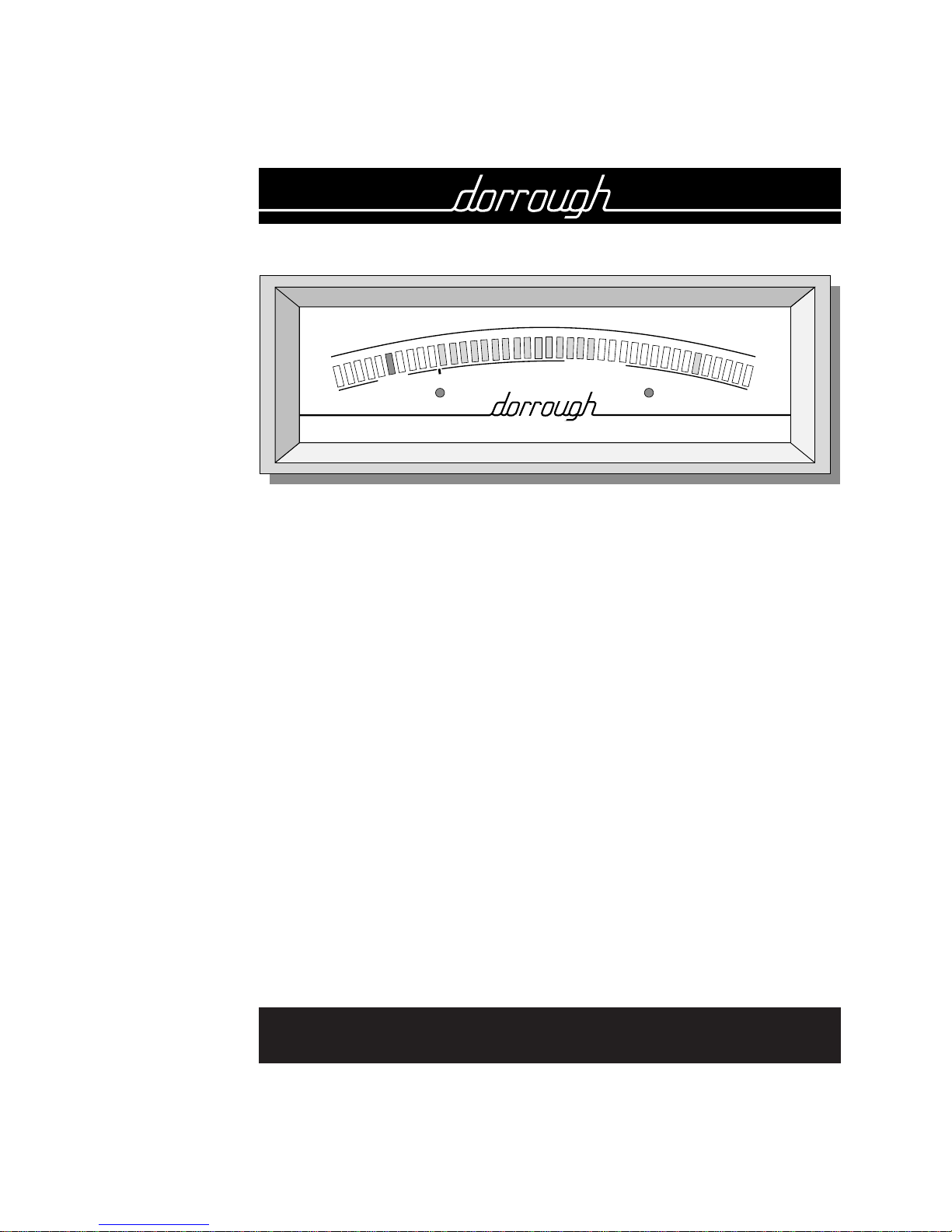
The DORROUGH Composite Video Luminance Meter, Model
VLM-40, is a simple, easy-to-use, video level meter designed
for quick dynamic measurements of video levels from any
connected NTSC source (e.g., camera, VTR, etc.).
Using a single 40-segment bar graph, the VLM-40
simultaneously displays three amplitude parameters of the
composite video signal: sync, average luminance, and peak
luminance. Two additional indicators detect the presence of
proper sync and setup levels.
Just like a traditional waveform monitor, the VLM-40’s peak-toaverage features enable you to quickly check lighting
conditions, contrast, drop-outs, sync stability, and video signal
quality. However, you’ll find it easier to use as you interpret
data on the single meter scale. The VLM-40 is insensitive to
chroma information, VITS (vertical interval test signals), and it
responds to luminance signals as short as 200 ns in length.
• INPUT IMPEDANCE
25 kΩ unterminated, 75 Ω terminated
• SYNC RANGE
-50 to -32 IRE units
• LUMINANCE RANGE
0 to 120 IRE units
• SYNC AND LUMINANCE FREQUENCY RESPONSE
Exceeds IRE frequency response
• MINIMUM PULSE WIDTH RESPONSE
200 ns
• METER RESOLUTION
Luminance scale is 4 IRE units; Sync scale is 2 IRE units
• DIMENSIONS
8
1
⁄4" W x 27⁄ 8"H x 61⁄2"D
DORROUGH Electronics constantly strives to meet or exceed the highest
professional standards. As a result of these efforts, modifications may be made
from time to time to existing products without prior notice. Specifications
and appearance may differ from those listed or shown in this manual.
© DORROUGH Electronics, 1994
DORROUGH Electronics
5221 Collier Place
Woodland Hills, CA 91364 USA
Voice: 818•998•2824 – FAX: 818•998•1507
VLM-40 NTSC TECHNICAL INSTRUCTION MANUAL
INTRODUCTION

2 – Description
The VLM-40 features a single 40-segment bar graph, as shown
in Fig. 1. Peak and average luminance are simultaneously
displayed on 30 LED segments over a range of 0 to 120 IRE
units (for a resolution of 4 IRE units). Average luminance levels
are indicated as a continuous bar, while peak levels are
displayed as a single LED above the bar. Luminance levels in
the 0 to 100 IRE range are displayed as green LED segments.
Levels over 100 IRE use red indicators for increased recognition.
Sync is displayed on one of ten yellow LED segments on an
expanded scale ranging from -52 to -30 IRE units (for a
resolution of 2 IRE units). A green LED indicates a proper sync
level of -40 IRE.
The front meter panel also includes sync and setup LEDs that
detect the status of these corresponding video levels. Under
normal operating conditions, the sync LED will be green
whenever the video source has a proper sync signal. If sync
drops out, the sync LED will flash red for single sync drop-outs
greater than 2 H, or stay on full for continuous drop-outs.
The setup LED is green whenever the video source has a Setup
level greater than 7.5 IRE units, and red when setup goes below
4 IRE. The examples in the Operation chapter (starting on
page 6) will explain how to use all these features in more detail.
SIMULTANEOUS PEAK AND
AVERAGE DISPLAY...
Fig. 1. The VLM-40’s 40-segment
bar graph displays sync, average,
and peak luminance video levels.
SYNC AND SETUP
VIOLATION LEDS...
VLM-40 NTSC T
ECHNICAL INSTRUCTION MANUAL
DESCRIPTION
COMPOSITE VIDEO LUMINANCE METER
MODEL VLM-40
-48
-40
0
20
40
60
80
100
120
© 1990
S
Y
N
C
L
U
M
I
N
A
N
C
E
I
R
E
U
N
I
T
S
-32
SYNC SETUP

Description – 3
REAR PANEL CONNECTIONS..
Fig. 2. The VLM-40’s rear panel
provides video connections and a
termination switch for 75 ohms or
loop connection (Hi-Z).
ABOUT THIS MANUAL...
As shown in Fig. 2, the VLM-40’s rear panel is equipped with
BNC connectors for video and loop, and a switch for 75-ohm
termination or loop connection. An ac power cord provides
power to the unit from a standard 115 V ac receptacle.
The VLM-40 weighs less than two pounds, can be easily read
from a distance of 20 feet, and may be installed in an optional
panel mount (e.g., DORROUGH Rack Mount Kit, 40-S for a
single meter or 40-D for dual meters) or operated as a standalone package.
The remainder of this Technical Instruction Manual is divided
into the following sections: Installation, Operation, Calibration,
and Circuit Schematics. Before you install the unit, take a
moment to read through the Operation chapter to fully
understand the capabilities of the VLM-40. After you have
determined how best to use the unit for your purposes, follow
the instructions listed in the Installation chapter.
VLM-40 NTSC TECHNICAL INSTRUCTION MANUAL
DESCRIPTION
AC Cord
DORROUGH ELECTRONICS
WOODLAND HILLS, CA 91364
Loop Through
Term.
Hi-Z
Gain
4 – Installation
VLM-40 NTSC TECHNICAL INSTRUCTION MANUAL
INSTALLATION
UNPACKING...
INITIAL SET-UP...
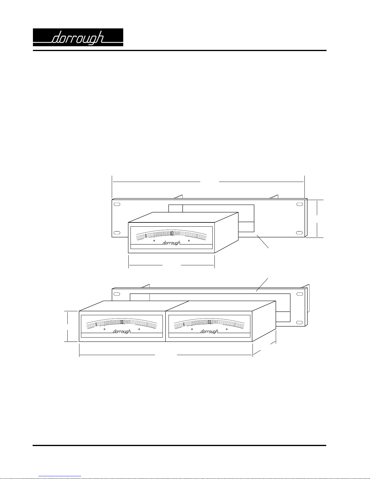
Fig. 3. Dimensions for mounting
a VLM-40 in an optional
Dorrough panel.
Your unit was carefully packed at the factory. Nevertheless,
please take a moment to examine it for any signs of shipping
damage. If damage is evident, retain the carton and notify the
transit carrier and your local distributor about your claim.
Once you are satisfied with the physical integrity of the unit,
follow the steps listed below to verify initial operation.
1. The VLM-40 can either be mounted in a panel or operated
as a stand-alone package.
• To panel-mount the VLM-40, refer to Fig. 3 for mounting
dimensions. Choose a ventilated area that provides a
minimum depth of 10" for proper cable routing.
• Consider a location that not only will offer easy
observation of the meter movements, but will also allow
convenient access to the back panel controls and
proximity to a 120 Vac receptacle.
• For stand-alone use, place the VLM-40 on any table top,
counter, or cabinet near a 120 Vac receptacle.
19.00 "
3.50 "
8.125 "
PANEL #40A-S
16.250 "
6.50 "
3.00 "
PANEL #40A-D
COMPOSITE VIDEO LUMINANCE METER
MODEL VLM-40
-48
-40
0
20
40
60
80
100
120
© 1990
S
Y
N
C
L
U
M
I
N
A
N
C
E
I
R
E
U
N
I
T
S
-32
SYNC SETUP
COMPOSITE VIDEO LUMINANCE METER
MODEL VLM-40
-48
-40
0
20
40
60
80
100
120
© 1990
S
Y
N
C
L
U
M
I
N
A
N
C
E
I
R
E
U
N
I
T
S
-32
SYNC SETUP
COMPOSITE VIDEO LUMINANCE METER
MODEL VLM-40
-48
-40
0
20
40
60
80
100
120
© 1990
S
Y
N
C
L
U
M
I
N
A
N
C
E
I
R
E
U
N
I
T
S
-32
SYNC SETUP
 Loading...