

Page 1
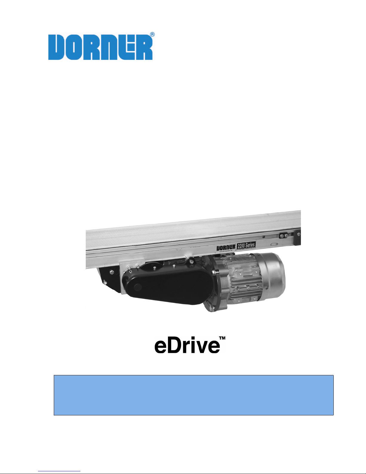
2200 and 2300 Series Mid
Mount Drive Package for
Standard & Heavy Load
Gearmotors
Installation, Maintenance & Parts Manual
Featuring:
DORNER MFG. CORP. INSIDE THE USA OUTSIDE THE USA
P.O. Box 20 • 975 Cottonwood Ave. TEL: 1-800-397-8664 TEL: 262-367-7600
Hartland, WI 53029-0020 USA FAX: 1-800-369-2440 FAX: 262-367-5827
For other service manuals visit our website at:
www.dorner.com/service_manuals.asp
851-734 Rev. B
Technology
Page 2
Table of Contents
IMPORTANT
Introduction ......................................................................... 2
Warnings - General Safety ................................................. 3
Specifications ...................................................................... 4
Gearmotor Mounting Package Models:........................... 4
Example:....................................................................... 4
Mid Mount Drive...................................................... 4
Gang Mid Side Mount Drive ................................... 4
Table 1: Gearmotor Specifications .................................. 5
U.S. Version ................................................................. 5
CE Version ................................................................... 5
Table 2: Belt Speeds for Standard &
Heavy Load Fixed Speed 90° Gearmotors ...................... 5
U.S. Version (60 Hz Gearmotors) ................................ 5
CE Version (50 Hz Gearmotors) .................................. 6
Table 3: Belt Speeds for Standard &
Heavy Load Variable Speed 90° DC Gearmotors ........... 6
U.S. Version ................................................................. 6
CE Version ................................................................... 6
Table 4: Belt Speeds for Heavy Load
Variable Speed 90° VFD Gearmotors ............................. 6
Table 5: Belt Speeds
for Brushless DC 90° Gearmotors ................................... 6
Table 6: RPM/Torque for Standard Load
Fixed Speed Parallel Shaft 60 Hz Gearmotors ............... 7
Table 7: RPM/Torque for Standard Load
Variable Speed Parallel Shaft VFD Gearmotors ............. 7
Table 8: RPM/Torque for Standard Load
Variable Speed Parallel Shaft DC Gearmotors ............... 7
Table 9: RPM/Torque for Brushless DC Parallel Shaft
Gearmotors....................................................................... 7
Table 10: Pulley Ratio / Timing Belt ............................... 8
Table 11: Conveyor Belt Speed Factor ............................ 8
Belt Speed Calculation: .................................................... 8
How to Calculate Belt Speed ........................................ 8
Installation............................................................................ 9
Required Tools ................................................................. 9
Mid Drive Installation ...................................................... 9
Bottom Mount Mid Drive Assembly ............................ 9
Side Mount Mid Drive Assembly ............................... 11
Gang Side Mount Mid Drive Assembly ..................... 12
Preventive Maintenance and Adjustment .......................... 13
Required Tools ............................................................... 13
Timing Belt Tensioning.................................................. 13
Timing Belt Replacement............................................... 13
Drive or Driven Pulley Replacement ............................. 14
Gear Reducer Replacement ............................................ 14
For e-Drive style gearmotor........................................ 15
For old style gearmotor prior to June 2011................. 16
Motor Replacement ........................................................ 17
Single Phase Motor ..................................................... 17
Three Phase Motor...................................................... 17
DC Variable Speed Motor .......................................... 17
Brushless Motor .......................................................... 17
All Models .................................................................. 18
Notes .................................................................................. 19
Service Parts....................................................................... 20
Bottom Mount Mid Drive Assembly.............................. 20
SEW Gearmotor.......................................................... 21
Side Mount Mid Drive Assembly .................................. 22
Gang Side Mount Mid Drive Assembly......................... 23
U.S. Version 90° Gearmotors ......................................... 24
CE Version 90° Gearmotors ........................................... 24
Parallel Shaft Gearmotors ............................................. 25
Return Policy...................................................................... 26
Introduction
Some illustrations may show guards
removed. Do NOT operate equipment without
guards.
Upon receipt of shipment:
• Compare shipment with packing slip. Contact factory
regarding discrepancies.
• Inspect packages for shipping damage. Contact carrier
regarding damage.
• Accessories may be shipped loose. See accessory instructions for installation.
2200 and 2300 Series Mid Mount Drive Package for Standard & Heavy Load Gearmotors
Dorner Mfg. Corp. 2 851-734 Rev. B
Dorner 2100 Series conveyors are covered by the following
patent numbers: 5,131,529, 5,174,435, and corresponding
patents and patent applications in other countries.
Dorner 2200 Series conveyors are covered by patent number
5,174,435, 6422382 and corresponding patents and patent
applications in other countries.
Dorner 6200 Series conveyors are covered by patent number
6,109,427, 6,298,981, 6,685,009 and corresponding patents
and patent applications in other countries.
Dorner’s Limited Warranty applies.
Dorner reserves the right to make changes at any time
without notice or obligation.
Dorner has convenient, pre-configured kits of Key Service
Parts for all conveyor products. These time saving kits are
easy to order, designed for fast installation, and guarantee
you will have what you need when you need it. Key Parts
and Kits are marked in the Service Parts section of this
manual with the Performance Parts Kits logo .
Page 3
Warnings - General Safety
A
A
A
A
A
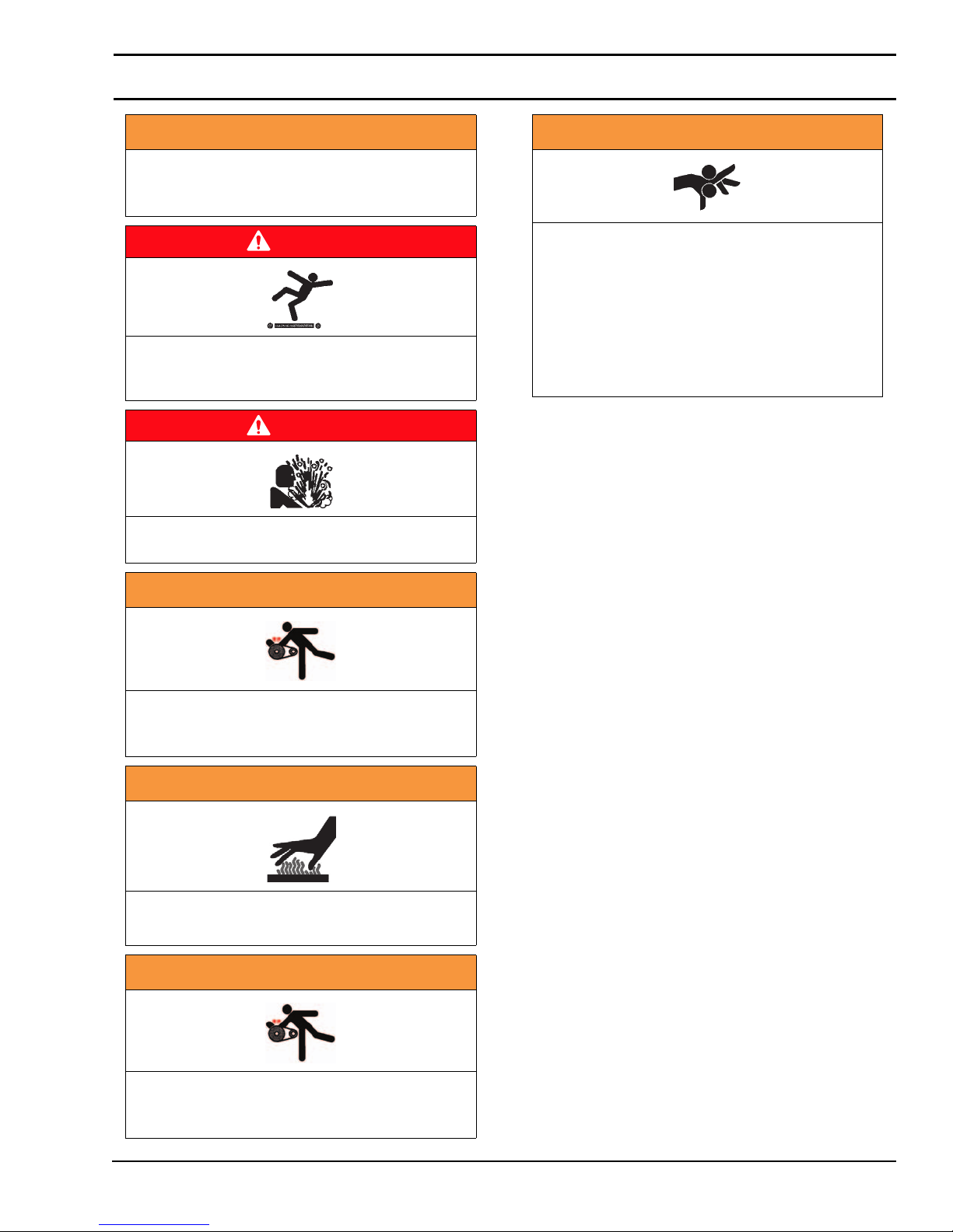
WARNING
The safety alert symbol, black triangle with
white exclamation, is used to alert you to
potential personal injury hazards.
DANGER
Climbing, sitting, walking or riding on
conveyor will cause severe injury. KEEP OFF
CONVEYORS.
DANGER
DO NOT OPERATE CONVEYORS IN AN
EXPLOSIVE ENVIRONMENT.
WARNING
Dorner cannot control the physical
installation and application of conveyors.
Taking protective measures is the
responsibility of the user.
When conveyors are used in conjunction
with other equipment or as part of a multiple
conveyor system, CHECK FOR POTENTIAL
PINCH POINTS and other mechanical
hazards before system start-up.
WARNING
Exposed moving parts can cause severe
injury. LOCK OUT POWER before removing
guards or performing maintenance.
WARNING
Gearmotors may be HOT.
DO NOT TOUCH Gearmotors.
WARNING
Exposed moving parts can cause severe
injury. REPLACE ALL GUARDS BEFORE
RUNNING CONVEYOR.
2200 and 2300 Series Mid Mount Drive Package for Standard & Heavy Load Gearmotors
851-734 Rev. B 3 Dorner Mfg. Corp.
Page 4
Specifications
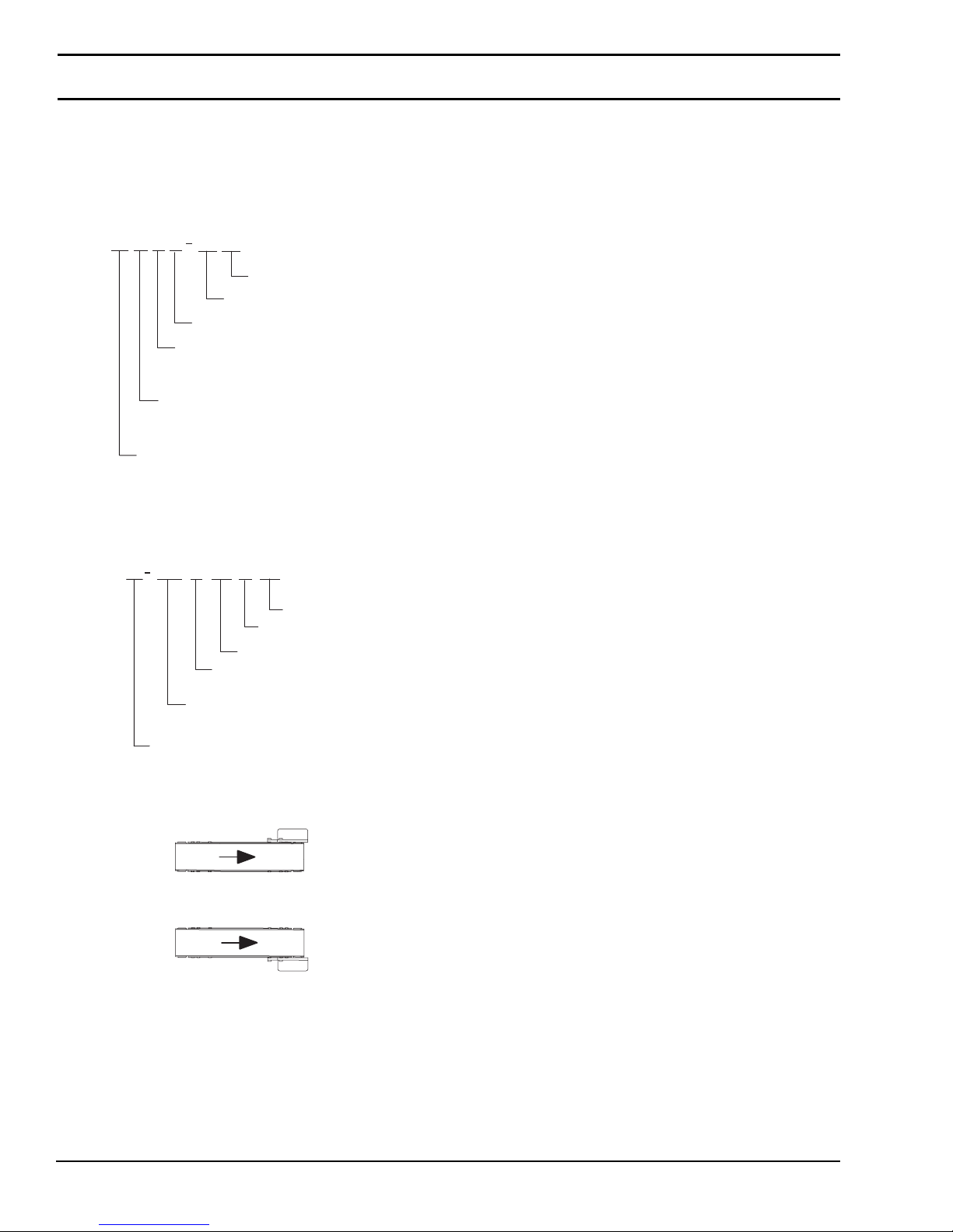
Gearmotor Mounting Package Models:
Example:
Mid Mount Drive
P
22M6
Gang Mid Side Mount Drive
22MGE
E
S
S A
Mount Style: B = Bottom
32 32
Drive Pulley
Mount Position = A or D
Gearmotor Type: S = Standard Load
Output Shaft: E = eDrive
S = Side
Q
WW
Gearmotor Type: S = Standard Load
GG
A
End Guard Length
Conveyor Quantity: D = Double
Distance between outer edges
of conveyor
Driven Pulley
H = Heavy Load
B = Brushless DC
P = Parallel
W = SEW
CC
Center Guard Length
Mount Position = A or D
T = Triple
H = Heavy Load
A
D
2200 and 2300 Series Mid Mount Drive Package for Standard & Heavy Load Gearmotors
Dorner Mfg. Corp. 4 851-734 Rev. B
Page 5
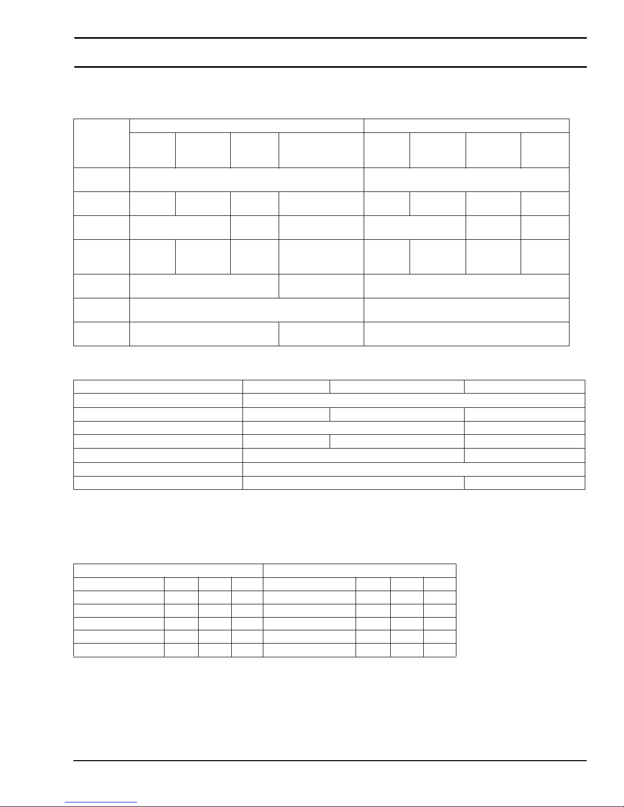
Table 1: Gearmotor Specifications
U.S. Version
Standard Load Gearmotor Heavy Load Gearmotor
DC
Variable
Speed
130VDC 115/230 Volts
NEMA 42CZ NEMA 56C
Brushless DC
Non-ventilated
Output
Power
Input
Voltage
Input
Frequency
Input
Current
(Amperes)
Gearmotor
Ratios
Frame
Size
Motor
Ty p e
Single-
Phase
115VAC 208 – 230/
5.0 1.2/0.6 2.2 8.8 / 3.4 7.4 2.1 – 2/1 1.6 5.0
5:1, 10:1, 20:1, 40:1, 60:1 10:1, 20:1, 50:1 5:1, 10:1, 20:1, 40:1, 60:1
Totally enclosed, Fan cooled Totally enclosed,
Three
Phase
0.25 hp (0.19 kw) 0.5 hp (0.37 kw)
460 VAC
60Hz N/A 60 Hz 60Hz 10 – 60Hz N/A
D.C.
Single-
Phase
115VAC 208 – 230/
Three
Phase
460 VAC
Totally enclosed, Fan cooled
Specifications
VFD
Variable
Speed
230 VAC 90VDC
DC
Variable
Speed
CE Version
Single Phase Three Phase VFD Variable Speed
Output Power 0.18 kw
Input Voltage 230 VAC 230/400 VAC 230 VAC
Input Frequency 50Hz 25 to 63 Hz
Input Current 1.6 Amperes 1.4/0.8 Amperes 1.4 Amperes
Gearmotor Ratios 5:1, 10:1, 20:1, 40:1, 60:1 5:1, 10:1, 20:1
Protection Rating IP55
Frame Size IEC 63 B5 IEC 71 B5
Table 2: Belt Speeds for Standard & Heavy Load Fixed Speed 90°
Gearmotors
U.S. Version (60 Hz Gearmotors)
Standard Load Gearmotors Heavy Load Gearmotors
Part Number RPM In-lb N-m Part Number RPM In-lb N-m
32M060EL4(vp)F(n) 29 226 25.5 32M060HS4(vp)F(n) 29 226 25.5
32M040EL4(vp)F(n) 43 237 26.8 32M040HS4(vp)F(n) 43 247 27.9
32M020EL4(vp)F(n) 86 142 16 32M020HS4(vp)F(n) 86 248 27.9
32M010EL4(vp)F(n) 173 78 8.8 32M010HS4(vp)F(n) 173 156 17.6
32M005EL4(vp)F(n) 345 41 4.6 32M005HS4(vp)F(n) 345 81 9.1
(vp) = voltage and phase
11 = 115 V, 1-phase
23 = 208 – 230/460 V, 3-phase
2200 and 2300 Series Mid Mount Drive Package for Standard & Heavy Load Gearmotors
851-734 Rev. B 5 Dorner Mfg. Corp.
Page 6
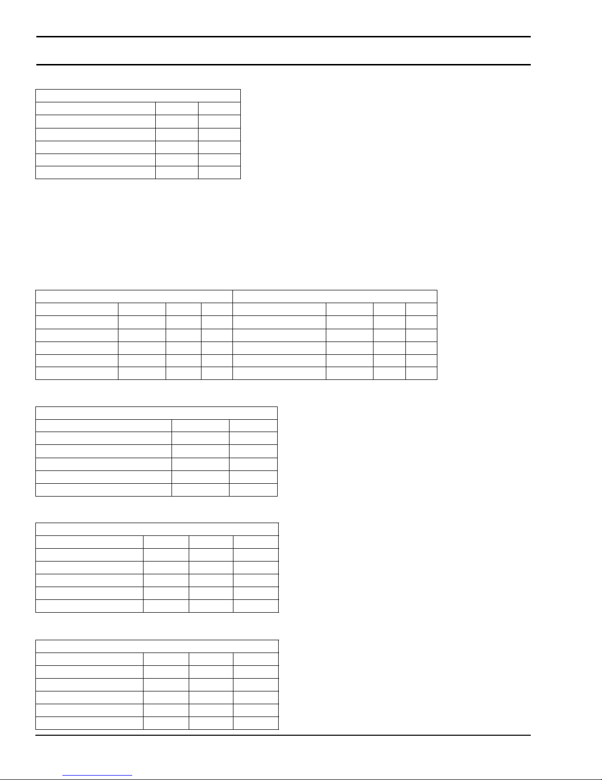
Specifications
CE Version (50 Hz Gearmotors)
Gearmotors
Par t Num ber RPM N-m
62Z060ES4(vp)FN 23 26.4
62Z040ES4(vp)FN 35 28.9
62Z020ES4(vp)FN 70 19.4
62Z010ES4(vp)FN 140 10.7
62Z005ES4(vp)FN 280 5.6
(vp) = voltage and phase
21 = 230 V, 1-phase
23 = 230 V, 3-phase
43 = 400 V, 3-phase
Table 3: Belt Speeds for Standard & Heavy Load Variable Speed 90° DC
Gearmotors
U.S. Version
Standard Load Gearmotors Heavy Load Gearmotors
Part Number RPM In-lb N-m Part Number RPM In-lb N-m
32M060ELD3DEN 5 - 42 198 22.4 32M060HSD9DEN 5 - 42 198 22.4
32M040ELD3DEN 8 - 63 163 18.4 32M040HSD9DEN 8 - 63 215 24.3
32M020ELD3DEN 15 - 125 98 11.1 32M020HSD9DEN 15 - 125 196 22.1
32M010ELD3DEN 30 - 250 54 6.1 32M010HSD9DEN 30 - 250 108 12.2
32M005ELD3DEN 61 - 500 28 3.2 32M005HSD9DEN 61 - 500 56 6.3
CE Version
Gearmotors
Part Number RPM N-m
62Z060ES423EN 9 - 23 26.4
62Z040ES423EN 14 - 35 28.9
62Z020ES423EN 28 - 70 19.4
62Z010ES423EN 56 - 140 10.7
62Z005ES423EN 112 - 280 5.6
Table 4: Belt Speeds for Heavy Load Variable Speed 90° VFD Gearmotors
Heavy Load Gearmotors
Part Number RPM In-lb N-m
32M060ES423EN 3-29 226 25.5
32M040ES423EN 5-43 247 27.9
32M020ES423EN 10-86 248 27.9
32M010ES423EN 20-173 156 17.6
32M005ES423EN 42-345 81 9.1
Table 5: Belt Speeds for Brushless DC 90° Gearmotors
Heavy Load Gearmotors
Part Number RPM In-lb N-m
62M060ESBDDEN 2-50 106 12.4
62M040ESBDDEN 3-75 123 14.3
62M020ESBDDEN 5-150 89 10.4
62M010ESBDDEN 10-300 49 5.7
62M005ESBDDEN 20-600 25 2.9
2200 and 2300 Series Mid Mount Drive Package for Standard & Heavy Load Gearmotors
Dorner Mfg. Corp. 6 851-734 Rev. B
Page 7
Specifications
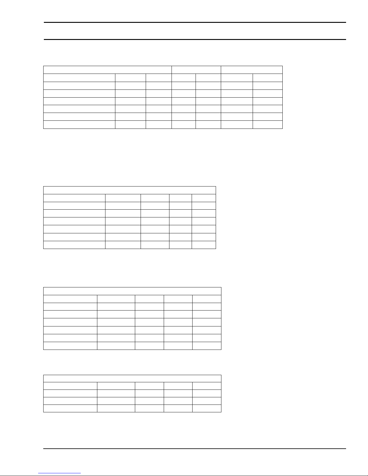
Table 6: RPM/Torque for Standard Load Fixed Speed Parallel Shaft 60 Hz
Gearmotors
Gearmotors* 1 Phase 3 Phase
Part Number Ratio RPM In-lb N-m In-lb N-m
62M180PS4(vp)F(n) 180:1 10 341 38.5 341 38.5
62M060PS4(vp)F(n) 60:1 29 270 30.5 270 30.5
62M030PS4(vp)F(n) 30:1 58 135 8.26 250 28.3
62M020PS4(vp)F(n) 20:1 86 90 10.2 167 18.9
62M010PS4(vp)F(n) 10:1 173 45 5.1 115 13
62M005PS4(vp)F(n) 5:1 345 25 2.8 58 6.5
(vp) = voltage and phase
11 = 115 V, 1-phase
23 = 230V, 3-phase
Table 7: RPM/Torque for Standard Load Variable Speed Parallel Shaft VFD
Gearmotors
Gearmotors*
Part Number Gear Ratio RPM* In-lb* N-m*
62M180PS423EN 180:1 1-10 341 38.5
62M060PS423EN 60:1 3-29 270 30.5
62M030PS423EN 30:1 6-58 250 28.3
62M020PS423EN 20:1 9-86 167 18.9
62M010PS423EN 10:1 17-173 115 13
62M005PS423EN 5:1 35-345 58 6.5
* At 60 Hz
(n) = reversing capability
N = no reversing switch
R = with reversing switch (115V, 1 phase only)
Table 8: RPM/Torque for Standard Load Variable Speed Parallel Shaft DC
Gearmotors
Gearmotors
Part Number Gear Ratio RPM In-lb N-m
62M180PSD3DEN 180:1 2-14 341 38.5
62M060PSD3DEN 60:1 5-42 270 30.5
62M030PSD3DEN 30:1 10-83 135 15.3
62M020PSD3DEN 20:1 16-125 90 10.2
62M010PSD3DEN 10:1 31-250 72 8.1
62M005PSD3DEN 5:1 63-500 25 2.8
Table 9: RPM/Torque for Brushless DC Parallel Shaft Gearmotors
Gearmotors
Part Number Gear Ratio RPM In-lb N-m
62M050PSBDDEN 50:1 2-60 240 28
62M020PSBDDEN 20:1 5-150 103 11.7
62M010PSBDDEN 10:1 10-300 52 5.9
2200 and 2300 Series Mid Mount Drive Package for Standard & Heavy Load Gearmotors
851-734 Rev. B 7 Dorner Mfg. Corp.
Page 8
Specifications
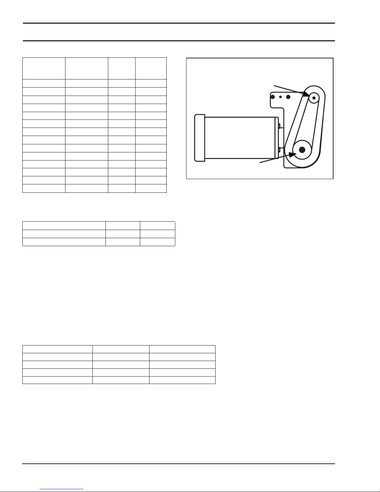
Table 10: Pulley Ratio / Timing Belt
Motor (Drive)
Pulley Teeth
22 32 0.69 814-104
28 28 1.00 814-104
28 32 0.88 814-065
32 22 1.45 814-104
32 28 1.14 814-065
44 22 2.00 814-065
44 28 1.57 814-101
44 32 1.38 814-108
48 22 2.18 814-101
48 28 1.71 814-108
48 32 1.50 814-108
60 22 2.73 814-064
60 28 2.14 814-064
60 32 1.88 814-099
Conveyor
(Driven)
Pulley Teeth
Table 11: Conveyor Belt Speed Factor
Pulley
Ratio
Timing
Belt
Figure 1
Driven Pulley
Drive Pulley
Figure 1
Conveyor Series/Type Ft / Min M / Min
2200 / 2300 0.35 0.107
2200 Precision Move 0.394 0.12
Belt Speed Calculation:
How to Calculate Belt Speed
1. Determine gearmotor RPM from tables 2-9.
2. Determine the pulley kit ratio. Count the number of teeth on the drive and driven pulleys following figure 1. Using table
10, look up pulley ratio based on pulley combinations.
3. Determine conveyor speed factor using table 11. Based on your conveyor type, select the appropriate factor.
4. Calculate belt speed:
Example: Belt Speed = Gearmotor RPM (tables 2-9) x Pulley Kit Ratio (table 10) x Conveyor Speed Factor (table 11)
2200 Series parallel shaft DC variable speed 20:1 gearmotor with 44 tooth sprocket on gearmotor (Drive) and 28 tooth
sprocket on the conveyor output shaft (Driven).
Gearmotor = 62M020PSD3DEN = 16 - 125 RPM
Pulley Kit = 44 t mtr. - 28 t conv. = 1.57
Speed Factor = 2200 Series = 0.350 ft/min per RPM
Minimum Belt Speed = 16 x 1.57 x 0.350 = 8.8 Ft/min
Maximum Belt Speed = 125 x 1.57 x 0.350 = 69 Ft/min
2200 and 2300 Series Mid Mount Drive Package for Standard & Heavy Load Gearmotors
Dorner Mfg. Corp. 8 851-734 Rev. B
Page 9
Installation
A
Required Tools
• Hex key wrenches:
2 mm, 2.5 mm, 3 mm, 5 mm
• Straight edge
• Torque wrench
Mid Drive Installation
WARNING
Exposed moving parts can cause severe
injury.LOCK OUT POWER before removing
guards or performing maintenance.
NOTE
Type 1 mounting package shown below left
(Figure 2). Type 2 mounting package shown
below right (Figure 2).
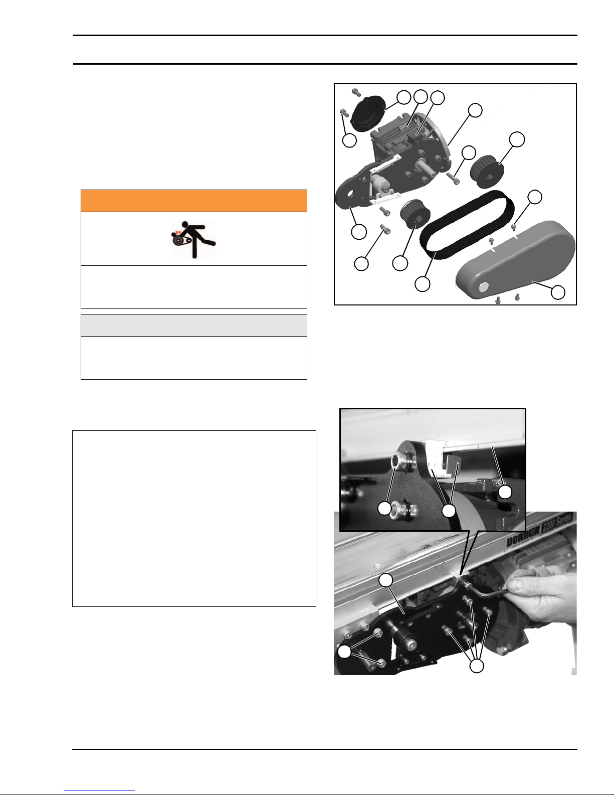
Bottom Mount Mid Drive Assembly
Installation Component List:
Figure 2
3
2
1
10
9
12
4
5
11
6
7
13
Figure 2
2. Install gearmotor and plate (Figure 3, item 1) onto
conveyor frame channel (Figure 3, item 2) with
retaining clip assembly (Figure 3, item 3) and socket
head screw (Figure 3, item 4).w Secure bottom with
two socket head screws (Figure 3, item 5). Do not
tighten screws at this time.
Figure 3
8
1 M6x12 Screws (2x)
2Cover
3 Drop-In Tee Bar
4 Frame Clamp Block
5 Gear Reducer
6 M6x25 Socket Head Screw
7 M4x8 Screws (4x)
8Drive Guard
9 M6x16 Socket Head Screws (2x)
10 Mount Assembly Bracket
11 Drive Pulley
12 Driven Pulley
13 Timing Belt
1. Gather installation components (Figure 2)
2
4
1
5
3
6
Figure 3
3. If required, change gearmotor position by removing four
(4) screws (Figure 3, item 6). Rotate gearmotor to other
position and replace screws. Tighten to 103 in-lb (12
Nm).
2200 and 2300 Series Mid Mount Drive Package for Standard & Heavy Load Gearmotors
851-734 Rev. B 9 Dorner Mfg. Corp.
Page 10
Installation
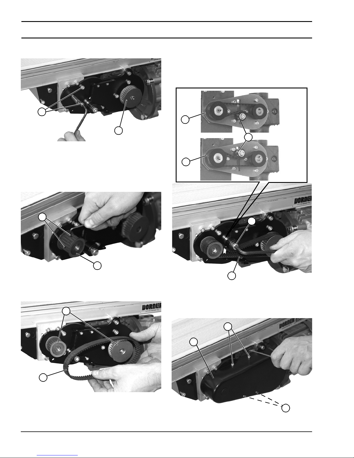
4. Tighten two socket head screws (Figure 4, item 1) to 60
in-lb (7 Nm).
Figure 4
1
2
Figure 4
5. Install drive pulley (Figure 4, item 2) onto gearmotor
shaft.
6. Install driven pulley (Figure 5, item 1) onto spindle
shaft. Tighten two set screws (Figure 5, item 2) to 35
in-lb (4 Nm).
Figure 5
8. Depending on direction of conveyor belt travel (Figure
7, item 1 or 2), position belt tensioner (Figure
7, item 3) as shown. Tension belt to obtain 0.125” (3
mm) deflection for 1.0 lb (456 grams) of force at belt
mid-point (Figure 7, item 4). Tighten tensioner screw
(Figure 7, item 5) to 103 in-lb (12 Nm).
Figure 7
1
3
2
2
1
Figure 5
7. Install belt (Figure 6, item 1) and both pulleys (Figure
6, item 2).
Figure 6
2
1
2
5
4
Figure 7
9. Install cover (Figure 8, item 1) onto drive assembly
with four M4 socket head screws (Figure 8, item 2).
Tighten screws to 35 in-lb (4 Nm).
Figure 8
2
1
Figure 6
2200 and 2300 Series Mid Mount Drive Package for Standard & Heavy Load Gearmotors
Dorner Mfg. Corp. 10 851-734 Rev. B
2
Figure 8
Page 11
Installation
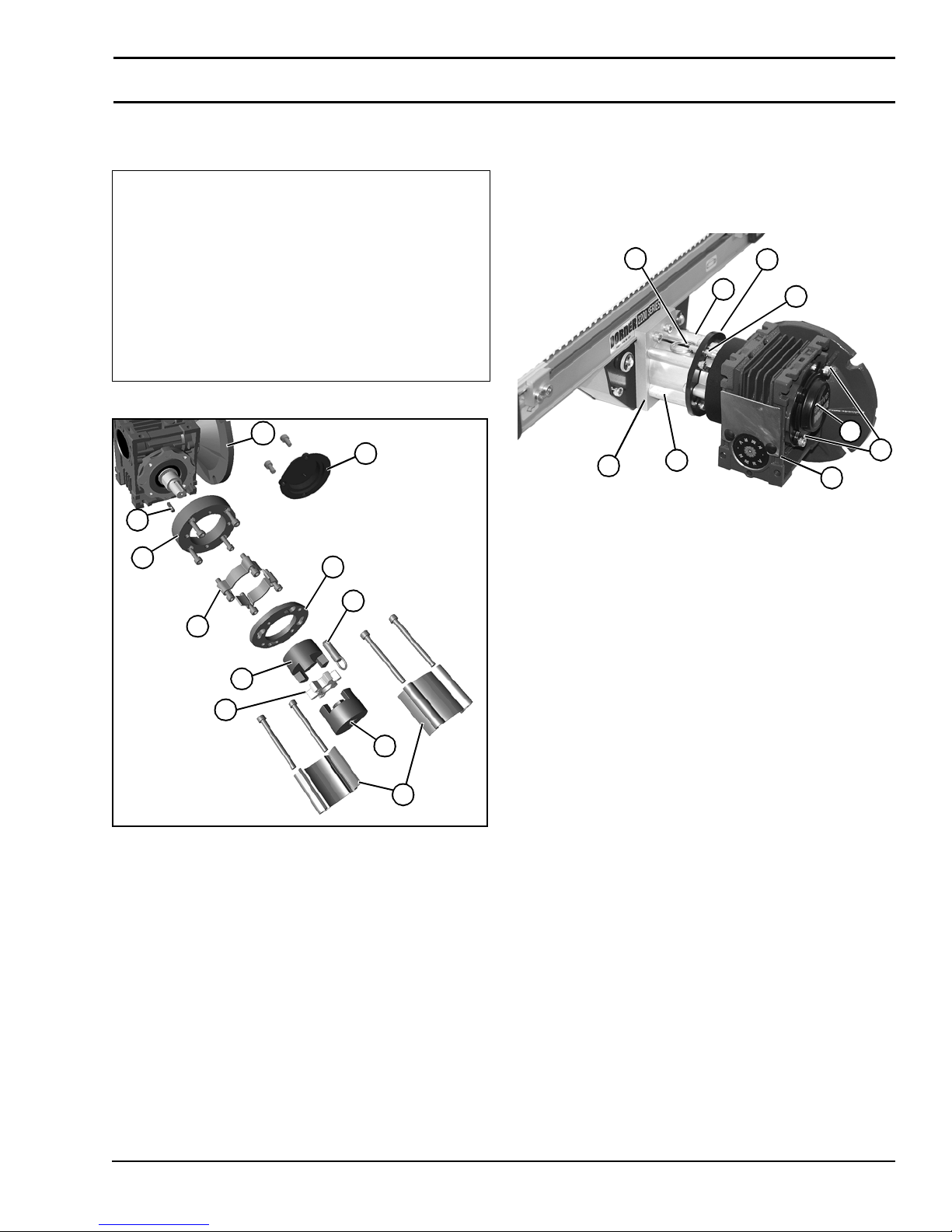
Side Mount Mid Drive Assembly
Installation Component List:
1Key
2 Spacer Ring
3 Short Side Drive Guard (2x)
4 Mounting Ring
5 3-Jaw Coupler (2x)
6 3-Jaw Spider
7 Quick Release Pin
8 Long Side Drive Guard (2x)
9Cover
10 Gear Reducer
1. Gather installation components (Figure 9)
Figure 9
10
9
1
2
3
5
4
7
2. Raise gearmotor assembly (Figure 10, item 1) into
position on mounting block (Figure 10, item 2). Install
two long side drive couplings (Figure 10, item 3) and
mounting ring (Figure 10, item 4) with four M6x70
socket head screws (Figure 10, item 5). Tighten screws
to 60 in-lb (7 Nm).
Figure 10
6
2
3
4
3
5
7
1
Figure 10
3. Install quick release pin (Figure 10, item 6) into
mounting ring to secure position.
4. Install motor onto gearmotor assembly (Figure
10, item 1). Tighten M6 motor mounting screws to 60
in-lb (7 Nm).
5. Install cover (Figure 10, item 7) with two M4 socket
head screws (Figure 10, item 8). Tighten screws
enough to secure cover.
8
6
Figure 9
5
8
2200 and 2300 Series Mid Mount Drive Package for Standard & Heavy Load Gearmotors
851-734 Rev. B 11 Dorner Mfg. Corp.
Page 12
Installation
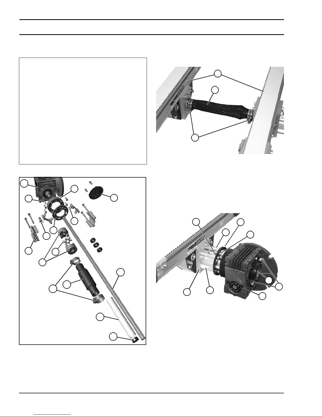
Gang Side Mount Mid Drive Assembly
Installation Component List:
1Key
2 Spacer Ring
3 Short Side Drive Guard (2x)
4 Mounting Ring
5 3-Jaw Coupler (2x)
6 3-Jaw Spider
7 Quick Release Pin
8 Long Side Drive Guard (2x)
9Cover
10 Mesh Sleeve
11 Hose Clamp (2x)
12 Shaft
13 Shaft Guard
14 Plug
15 Gear Reducer
1. Gather installation components (Figure 11)
Figure 11
15
2
1
9
2. Install protective cover (Figure 12, item 1) and two
clamps (Figure 12, item 2) onto shaft, and install
assembly between conveyor sections (Figure
12, item 3).
Figure 12
3
1
2
Figure 12
3. Raise gearmotor assembly (Figure 13, item 1) into
position on shaft (just installed) and on mounting block
(Figure 13, item 2). Install two long side drive
couplings (Figure 13, item 3) and mounting ring
(Figure 13, item 4) with four M6x70 socket head
screws (Figure 13, item 5). Tighten screws to 60 in-lb
(7 Nm).
Figure 13
3
4
7
8
6
5
12
10
11
13
6
2
3
4
3
5
7
8
1
Figure 13
4. Install quick release pin (Figure 13, item 6) into
mounting ring to secure position.
14
5. Install motor onto gearmotor assembly (Figure
13, item 1). Tighten M6 motor mounting screws to 60
Figure 11
in-lb (7 Nm).
6. Install cover (Figure 13, item 7) with two M4 socket
head screws (Figure 13, item 8). Tighten screws
enough to secure cover.
2200 and 2300 Series Mid Mount Drive Package for Standard & Heavy Load Gearmotors
Dorner Mfg. Corp. 12 851-734 Rev. B
Page 13
Preventive Maintenance and Adjustment
A
A
Required Tools
• Hex key wrenches:
2 mm, 2.5 mm, 3 mm, 5 mm
• Adjustable wrench (for hexagon head screws)
• Straight edge
• Torque wrench
Timing Belt Tensioning
WARNING
Exposed moving parts can cause severe
injury.LOCK OUT POWER before removing
guards or performing maintenance.
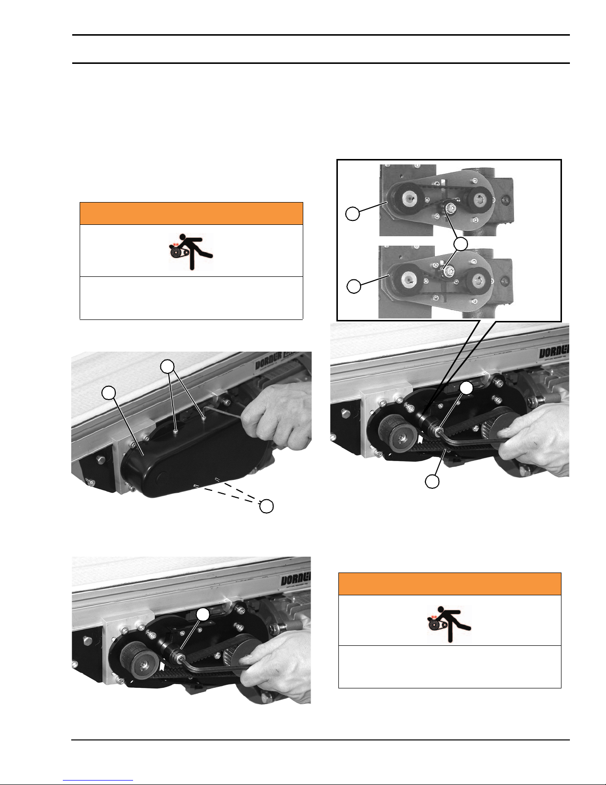
1. Remove four (4) screws (Figure 14, item 1) and
remove cover (Figure 14, item 2).
Figure 14
1
2
3. Depending direction of conveyor belt travel (Figure
16, item 1 or 2), position belt tensioner (Figure
16, item 3) as shown. Tension belt to obtain 0.125” (3
mm) deflection for 1.0 lb (456 grams) of force at belt
mid-point (Figure 16, item 4). Tighten tensioner screw
to 103 in-lb (12 Nm).
Figure 16
1
3
2
2
5
Figure 14
2. Loosen tensioner (Figure 15, item 1).
Figure 15
2
1
Figure 15
2200 and 2300 Series Mid Mount Drive Package for Standard & Heavy Load Gearmotors
851-734 Rev. B 13 Dorner Mfg. Corp.
4
1
4. Install cover (Figure 14, item 2) with four (4) screws
(Figure 14, item 1). Tighten screws to 35 in-lb (4 Nm).
Figure 16
Timing Belt Replacement
WARNING
Exposed moving parts can cause severe
injury. LOCK OUT POWER before removing
guards or performing maintenance.
1. Remove four (4) screws (Figure 14, item 1) and
remove cover (Figure 14, item 2).
2. Loosen tensioner (Figure 15, item 1).
Page 14
Preventive Maintenance and Adjustment
A
A
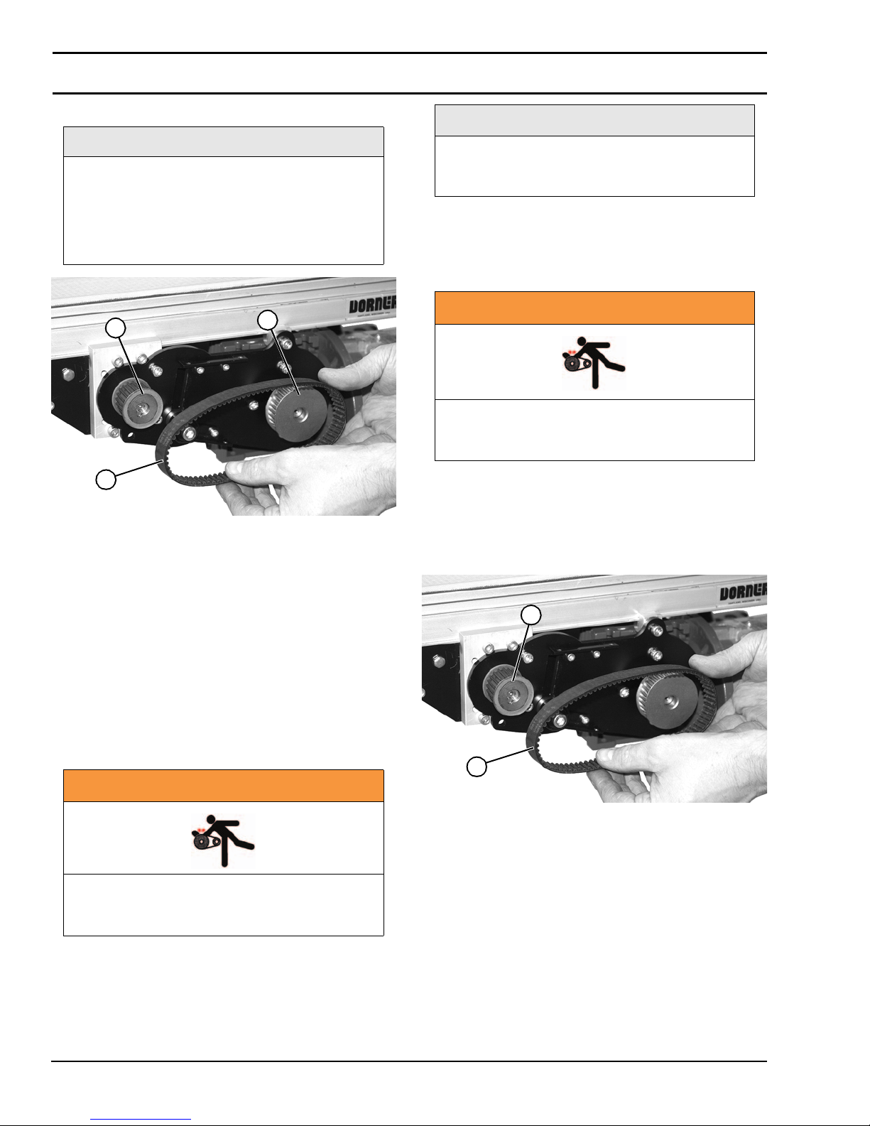
3. Remove timing belt (Figure 17, item 1).
NOTE
If timing belt does not slide over driven pulley
(Figure 17, item 3) flange, loosen driven
pulley set screws and remove pulley with belt
(Figure 17, item 1). For re-installation, see
steps 7 and 8 of "Bottom Mount Mid Drive
Assembly" story on page 8.
Figure 17
If drive pulley (Figure 17, item 2) is replaced,
wrap timing belt around drive pulley and
complete step 3.
3. Complete steps 7 through 9 of "Bottom Mount Mid
Drive Assembly" story on page 8.
Gear Reducer Replacement
NOTE
3
1
Figure 17
4. Install new timing belt around drive pulley (Figure
17, item 2) and driven pulley (Figure 17, item 3).
5. Depending direction of conveyor belt travel (Figure
16, item 1 or 2), position belt tensioner (Figure
16, item 3) as shown. Tension belt to obtain 0.125” (3
mm) deflection for 1.0 lb (456 grams) of force at belt
mid-point (Figure 16, item 4). Tighten tensioner screw
to 103 in-lb (12 Nm).
6. Install cover (Figure 14, item 1) with four (4) screws
(Figure 14, item 2). Tighten screws to 35 in-lb (4 Nm).
2
WARNING
Exposed moving parts can cause severe
injury. LOCK OUT POWER before removing
guards or performing maintenance.
1. Remove four (4) screws (Figure 14, item 2) and
remove cover (Figure 14, item 1).
2. Loosen tensioner (Figure 15, item 1).
3. Loosen driven pulley set screws and remove driven
pulley (Figure 18, item 1) and timing belt (Figure
18, item 2).
Figure 18
1
Drive or Driven Pulley Replacement
WARNING
Exposed moving parts can cause severe
injury. LOCK OUT POWER before removing
guards or performing maintenance.
1. Complete steps 1 through 3 of “Timing Belt
Replacement” section on page 13.
2. Loosen set screws and remove drive or driven pulley.
2200 and 2300 Series Mid Mount Drive Package for Standard & Heavy Load Gearmotors
Dorner Mfg. Corp. 14 851-734 Rev. B
2
Figure 18
Page 15
Preventive Maintenance and Adjustment
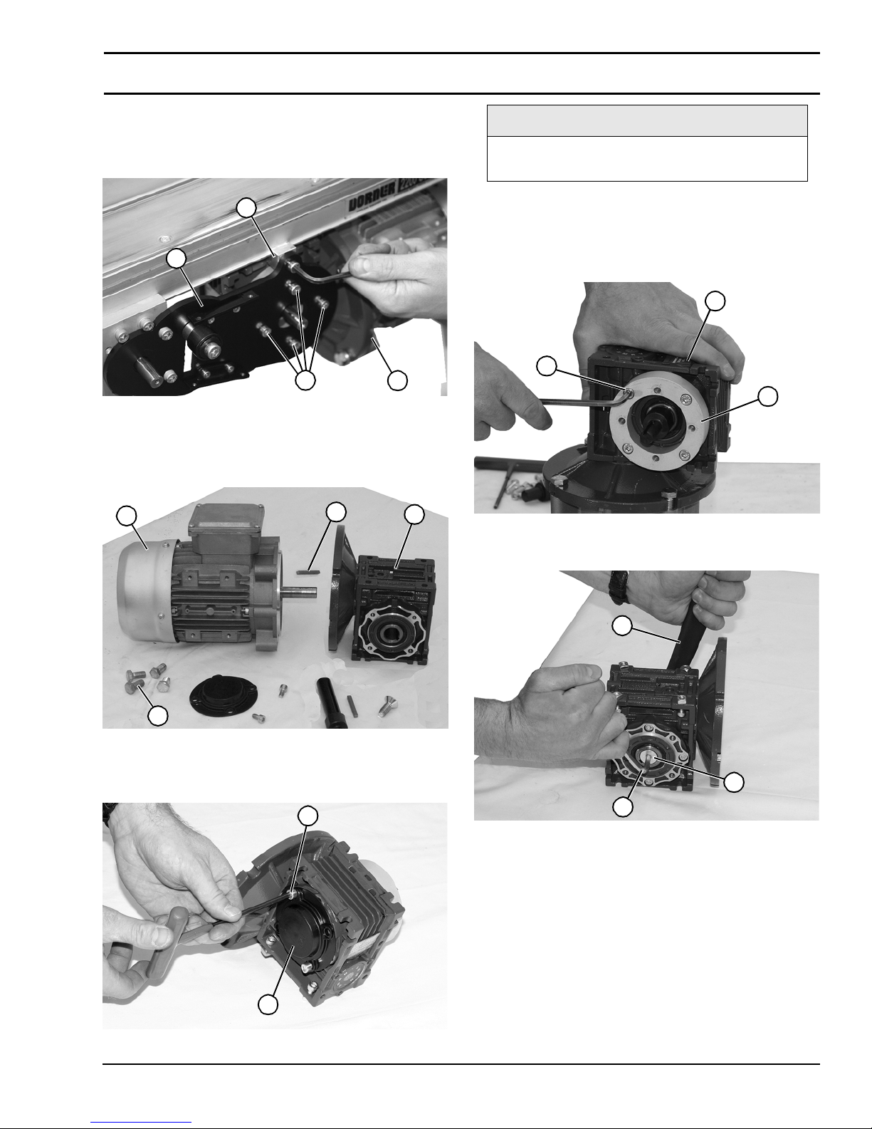
4. Remove four (4) gear reducer mounting screws (Figure
19, item 1) and retaining clip (Figure 19, item 2).
Remove gearmotor (Figure 19, item 3) from mounting
plate (Figure 19, item 4).
Figure 19
NOTE
Follow proper procedure below depending
upon old or new style gearmotor assembly.
2
4
1
3
Figure 19
5. Remove four screws (Figure 20, item 1). Detach motor
(Figure 20, item 2) from gear reducer (Figure
20, item 3). Retain shaft key (Figure 20, item 4).
Figure 20
2
4
3
For e-Drive style gearmotor
1. Loosen four (4) socket head screws (Figure 22, item 1)
and detach spacer (Figure 22, item 2) from gear reducer
(Figure 22, item 3).
Figure 22
3
1
2
Figure 22
2. Loosen driveshaft bolt (Figure 23, item 1).
Figure 23
1
Figure 20
6. Remove two (2) screws (Figure 21, item 1) and detach
output shaft cover (Figure 21, item 2).
Figure 21
1
2
2
1
3
Figure 23
3. Hold the driveshaft with a wrench (Figure 23, item 2)
as shown to keep shaft from turning, while removing
screw with hex wrench (Figure 23, item 3).
Figure 21
2200 and 2300 Series Mid Mount Drive Package for Standard & Heavy Load Gearmotors
851-734 Rev. B 15 Dorner Mfg. Corp.
Page 16
Preventive Maintenance and Adjustment
IMPORTANT
IMPORTANT
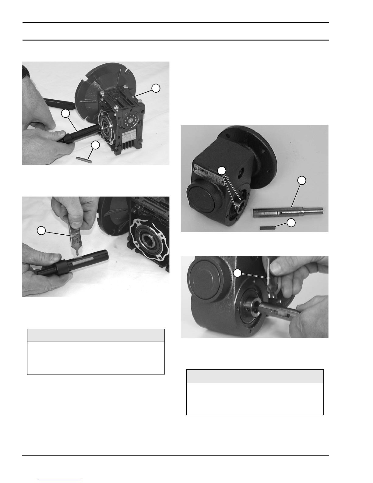
4. Remove driveshaft (Figure 24, item 1) and key (Figure
24, item 2).
Figure 24
3
1
2
Figure 24
5. Replace gear reducer (Figure 24, item 3).
6. Apply anti-seize (Figure 25, item 1) to shaft.
Figure 25
1
10. Install spacer (Figure 22, item 2) onto gear reducer
(Figure 22, item 3) with four (4) socket head screws
(Figure 22, item 1).
11. Complete steps 7 through 9 of "Bottom Mount Mid
Drive Assembly" story on page 8.
For old style gearmotor prior to June 2011
1. Loosen six (6) set screws (Figure 26, item 1). Remove
drive shaft (Figure 26, item 2) and key (Figure
26, item 3).
Figure 26
1
2
3
Figure 26
Figure 25
7. Replace the original shaft components into new gear
reducer (Figure 24).
Be extremely careful when coupling motor to
gear reducer. Avoid misalignment and forcing
the connection causing possible permanent
gear reducer seal damage.
8. Hold the driveshaft with a wrench (Figure 23, item 2)
as shown to keep shaft from turning, while installing
screw with hex wrench (Figure 23, item 3). Tighten
screw to 100 in-lb (11.5 Nm) for 42CZ or 350 in-lb
(39.5 Nm) for 52C, 63B5 and 71B5.
9. Apply anti-seize to motor shaft before assembling to
gearbox. With key (Figure 20, item 4) in keyway, slide
motor (Figure 20, item 2) and gear reducer (Figure
20, item 3) together. Install screws (Figure 20, item 1)
and tighten.
2. Apply anti-seize (Figure 27, item 1) to shaft.
Figure 27
1
Figure 27
3. Replace the original shaft components into new gear
reducer (Figure 26).
Be extremely careful when coupling motor to
gear reducer. Avoid misalignment and forcing
the connection causing possible permanent
gear reducer seal damage.
2200 and 2300 Series Mid Mount Drive Package for Standard & Heavy Load Gearmotors
Dorner Mfg. Corp. 16 851-734 Rev. B
Page 17
Preventive Maintenance and Adjustment
A
4. Apply anti-seize to motor shaft before assembling to
gearbox. With key (Figure 34, item 4) in keyway, slide
motor (Figure 34, item 2) and gear reducer (Figure
34, item 3) together. Install screws (Figure 34, item 1)
and tighten.
5. Complete steps 7 through 8 of "Bottom Mount Mid
Drive Assembly" story on page 8.
Motor Replacement
WARNING
Exposed moving parts can cause severe
injury. LOCK OUT POWER before removing
guards or performing maintenance.
DANGER
Three Phase Motor
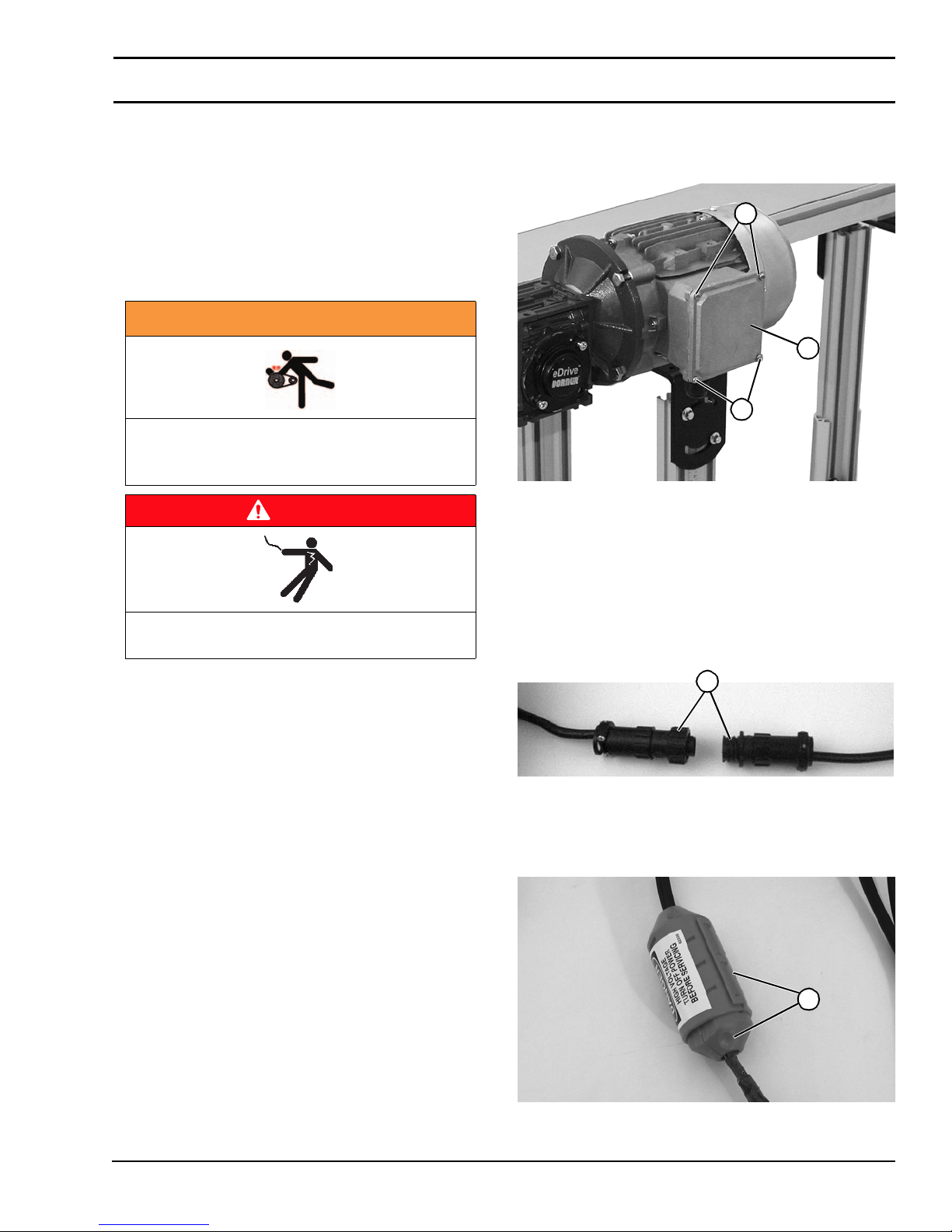
1. Loosen terminal box screws (Figure 28, item 1) and
remove cover (Figure 28, item 2).
Figure 28
1
2
1
Figure 28
2. Record wire colors on terminals 1, 2 and 3. Loosen wire
nuts and remove wires 1, 2 and 3.
3. Loosen cord grip and remove cord.
Hazardous voltage will cause severe injury or
death. LOCK OUT POWER BEFORE WIRING.
Single Phase Motor
1. For single phase motor, unplug power cord from outlet.
DC Variable Speed Motor
1. For DC variable speed motor, unplug motor cord at
disconnect (Figure 29, item 1).
Figure 29
1
Figure 29
Brushless Motor
1. Twist covers (Figure 30, item 1) apart.
Figure 30
1
2200 and 2300 Series Mid Mount Drive Package for Standard & Heavy Load Gearmotors
851-734 Rev. B 17 Dorner Mfg. Corp.
Figure 30
Page 18
Preventive Maintenance and Adjustment
IMPORTANT
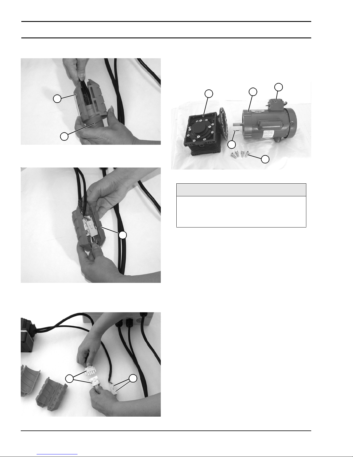
2. Remove outer cord cover (Figure 31, item 1) from
inner cord cover (Figure 31, item 2).
Figure 31
1
2
Figure 31
3. Open inner cord cover (Figure 32, item 1).
Figure 32
All Models
1. Remove four (4) screws (Figure 34, item 1). Detach
motor (Figure 34, item 2) from gear reducer (Figure
34, item 3). Retain motor output shaft key (Figure
34, item 4).
Figure 34
3
4
2
Figure 34
Be extremely careful when coupling motor to
gear reducer. Avoid misalignment and forcing
the connection causing possible permanent
gear reducer seal damage.
5
1
1
Figure 32
4. Unplug motor cord connectors (Figure 33, item 1) and
signal cable connectors (Figure 33, item 2).
Figure 33
1
2
2. With key (Figure 34, item 4) in keyway, slide motor
(Figure 34, item 2) and gear reducer (Figure
34, item 3) together, noting where position of switch
(Figure 34, item 5) will be during installation on
conveyor.
3. Install screws (Figure 34, item 1) and tighten to 60 inlb (7 Nm).
4. Replace wiring:
• For a single phase motor, reverse step 1 in “Single Phase
Motor” on page 17.
• For a three phase motor, reverse steps 1-3, in “Three Phase
Motor” on page 17.
• For a DC variable speed motor, reverse step 1 on “DC
Variable Speed Motor” on page 17.
• For a brushless motor, reverse steps 1-2 on “Brushless
Motor” on page 17.
Figure 33
2200 and 2300 Series Mid Mount Drive Package for Standard & Heavy Load Gearmotors
Dorner Mfg. Corp. 18 851-734 Rev. B
Page 19

Notes
2200 and 2300 Series Mid Mount Drive Package for Standard & Heavy Load Gearmotors
851-734 Rev. B 19 Dorner Mfg. Corp.
Page 20
Service Parts
NOTE
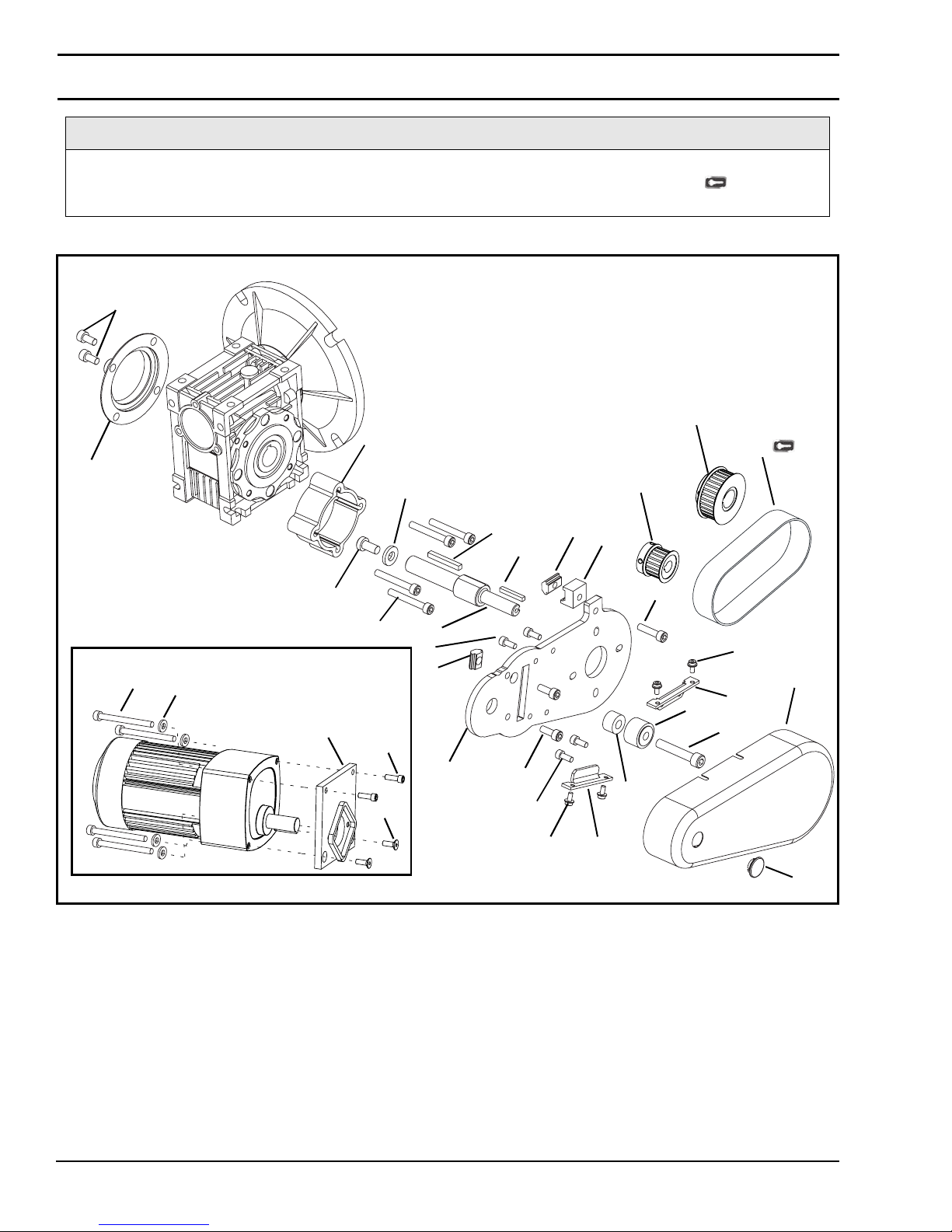
For replacement parts other than those shown in this section, contact an authorized Dorner Service Center
or the factory. Key Service Parts and Kits are identified by the Performance Parts Kits logo . Dorner
recommends keeping these parts on hand.
Bottom Mount Mid Drive Assembly
15
26
20
16
23
25
24
Parallel Shaft Option
31
30
22
27
21
28
29
11
17
7
10
9
4
13
10
8
5
1
14
6
5
2
18
19
3
12
11
2200 and 2300 Series Mid Mount Drive Package for Standard & Heavy Load Gearmotors
Dorner Mfg. Corp. 20 851-734 Rev. B
Page 21
Service Parts
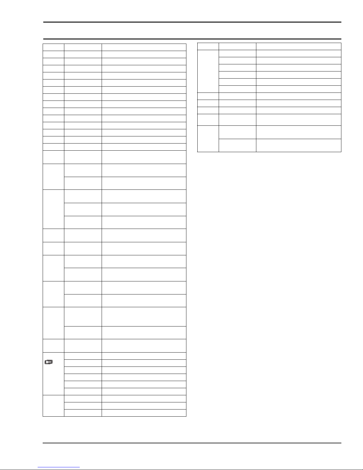
Item Part Number Description
1 802-046 Bearing Cam
2 807-226 Snap-out Plastic Plug
3 201894 Mounting Plate
4 202481 Frame Clamp Block
5 450375 Mounting Cover Bracket
6 450445 Spacer
7 202390M Nut
8 450376M Drive Guard
9 639971M Drop-In Tee Bar
10 920481M Socket Head Screw, M4-0.70 x 8 mm
11 920512M Socket Head Screw, M5-0.70 x 12 mm
12 920616M Socket Head Screw, M6-1.00 x 16 mm
13 920625M Socket Head Screw, M6-1.00 x 25 mm
14 920845M Socket Head Screw, M8-1.25 x 45 mm
15 920612M Socket Head Screw, M6-1.00 x 12 mm
(for 90°Gearmotors Only)
16 807-2059 Cover (for 42CZ C Face Gearmotors)
(for 90°Gearmotors Only)
807-2016 Cover (for 56 C Face Gearmotors)
(for 90°Gearmotors Only)
17 202272 Output Shaft (for 42CZ C Face 90°
Gearmotors Only)
350122 Output Shaft (for 56 C Face 90°
Gearmotors Only)
201677 Output Shaft
(for SEW Gearmotors Only))
18 912-084 Square Key, 0.188 x 1.50
(for 90°Gearmotors Only)
19 980422M Square Key 4 mm x 22 mm
(for 90°Gearmotors Only)
20 202270 Spacer (for 42CZ C Face Gearmotors)
(for 90°Gearmotors Only)
350115 Spacer (for 56 C Face Gearmotors)
(for 90°Gearmotors Only)
21 920645M Socket Head Screw, M6-1.00 x 12 mm
(for 90°Gearmotors Only)
920625M Socket Head Screw, M6-1.00 x 25 mm
(for SEW Gearmotors Only)
22 920893M Low Head Cap Screw, M8-1.25 x 16
mm (for 42CZ C Face 90°
Gearmotors)
931020M Flat Head Screw, M10-0.50 x 20 mm
(for 56 C Face 90° Gearmotors)
23 605280P Washer
(for 42CZ C Face 90° Gearmotors)
24 814-104 Timing Belt, 15mm W x 450mm L
814-065 Timing Belt, 15mm W x 475mm L
814-101 Timing Belt, 15mm W x 500mm L
814-108 Timing Belt, 15mm W x 520mm L
814-064 Timing Belt, 15mm W x 535mm L
814-099 Timing Belt, 15mm W x 565mm L
25 450366MP Driven Pulley, 22Tooth, 12mm bore
450367MP Driven Pulley, 28Tooth, 12mm bor e
450368MP Driven Pulley, 32Tooth, 12mm bor e
Item Part Number Description
26 450434 Drive Pulley, 22Tooth, 0.75" bore
450435 Drive Pulley, 28Tooth, 0.75" bore
450436 Drive Pulley, 32Tooth, 0.75" bore
450437 Drive Pulley, 44Tooth, 0.75" bore
450438 Drive Pulley, 48Tooth, 0.75" bore
450439 Drive Pulley, 60Tooth, 0.75" bore
27 450029M Adaptor Plate Assembly
28 902-157 Sock Cap Head Screw, 1/4-28 x 0.75”
29 903-161 Flat Cap Head Screw, 1/4-28 x 0.75”
30 911-120 Washer, (for 50:1 Brushless DC Motor
31 920890M Socket Head Screw, M8 x 90mm
920875M Socket Head Screw, M8 x 75mm
only)
(for 50:1 Brushless DC Motor only)
(for 10:1 Brushless DC Motor only)
2200 and 2300 Series Mid Mount Drive Package for Standard & Heavy Load Gearmotors
851-734 Rev. B 21 Dorner Mfg. Corp.
Page 22
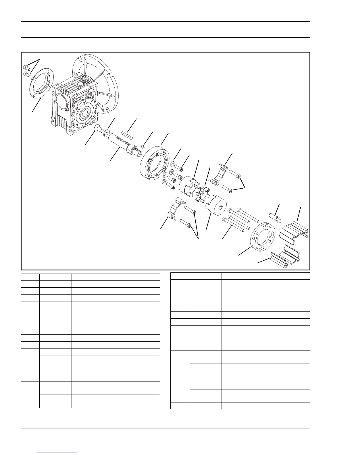
Service Parts
Side Mount Mid Drive Assembly
14
9
13
10
16
11
Item Part Number Description
1 807-1143 3-Jaw Spider
2 807-1169 Quick Release Pin
3 807-1566 3 Jaw Coupling
4 202359 Long Side Drive Guard (x2)
5 301092 Short S ide Dr ive Guard (x2)
6 301094 Mounting Ring
201722 Mounting Ring
7 920630M Socket Head Screw, M6-1.00 x 30 mm
8 920670M Socket Head Screw, M6-1.00 x 70 mm
9 807-2059 Cover (for 42CZ C Face Gearmotors)
807-2016 Cover (for 56 C Face Gearmotors)
10 912-084 Square Key, 0.188 x 1.50
912-077 Square Key, 0.188 x 0 .62
11 202273 Output Shaft (for 42CZ C Face
350120 Output Shaft (for 56 C Face Gearmotors)
201692 Output Shaft (for SEW Gearmotors Only)
(for SEW Gearmotors Only)
(for SEW Gearmotors Only)
Gearmotors)
17
12
19
15
18
5
1
7
5
3
7
8
6
4
Item Part Number Description
12 400026 Spacer Ring (for 42CZ C Face
Gearmotors)
350115 Adapter Ring (for 56 C Face Gearmotors)
201681 Adapter Ring
(for SEW Gearmotors Only)
13 605280P Washer (for 42CZ C Face Gearmotors)
14 920612M Socket Head Screw, M6-1.00 x 12 mm
15 920620M Socket Head Screw, M6-1.00 x 20 mm
920616M Flat Head Screw, M6-1.00 x 16 mm (for
16 920893M Low Head Cap Screw, M8-1.25 x 16 mm
931020M Flat Head Screw, M10-0.50 x 20 mm (for
17 980416M Square Key, 4 mm x 16 mm
18 807-1566 3 Jaw Coupling
807-1141 3 Jaw Coupling
19 807-2092 Washer (for SEW Gearmotors Only)
(for 56 C Face Gearmotors)
SEW Gearmotors Only)
(for 42CZ C Face Gearmotors)
56 C Face Gearmotors)
(for SEW Gearmotors Only)
2
4
2200 and 2300 Series Mid Mount Drive Package for Standard & Heavy Load Gearmotors
Dorner Mfg. Corp. 22 851-734 Rev. B
Page 23
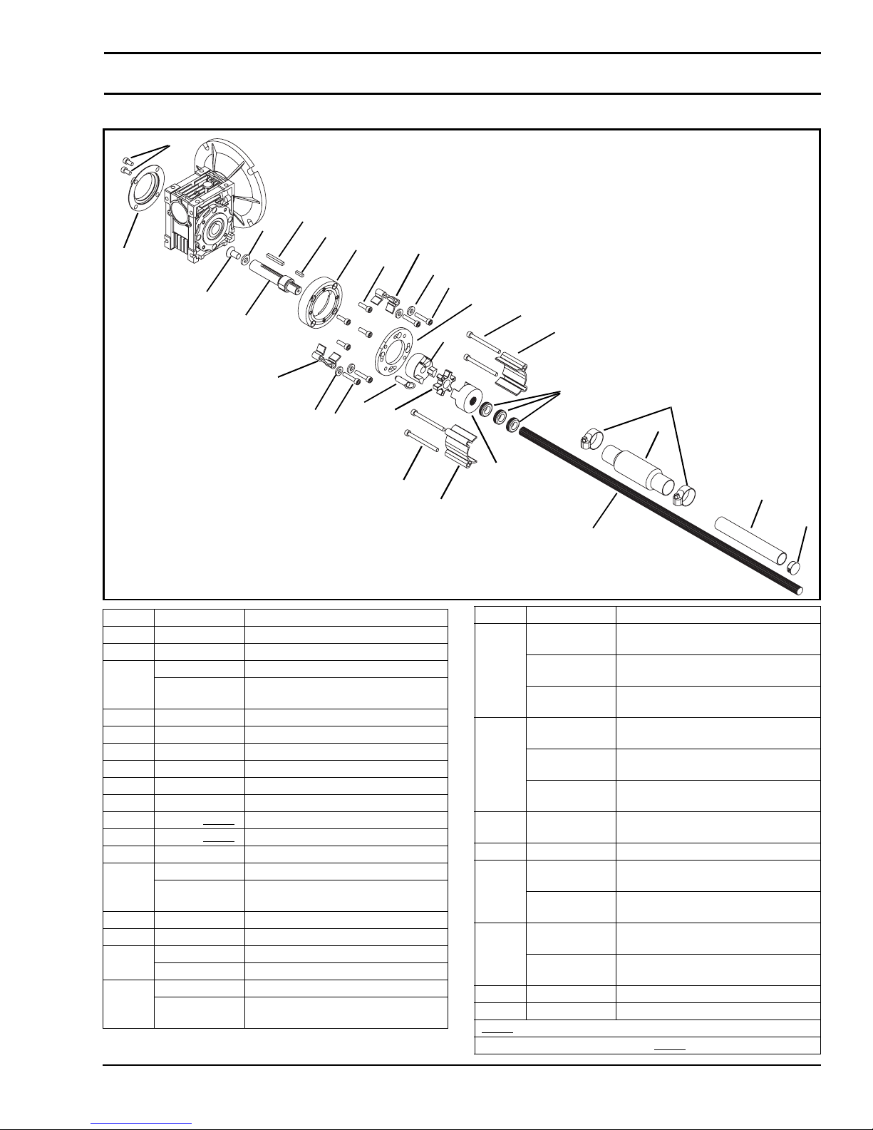
Gang Side Mount Mid Drive Assembly
21
17
20
16
23
18
24
19
22
12
25
14
3
13
Service Parts
15
9
12
2
25
14
1
15
Item Part Number Description
1 807-1143 3-Jaw Spider
2 807-1169 Quick Release Pin
3 807-1566 3-Jaw Coupling, 12 mm
807-1141 3-Jaw Coupling, (for SEW
4 807-2109 Hose Clamp
5 807-2110 Mesh Sleeve
6207-2113Plug
7 812-079 Grommet
8 202358 3-Jaw Coupling, 0.60"
9 202359 Long Side Drive Guard (x2)
10 202432-LLLLL
11 202462-LLLLL
12 301092 Short Side Drive Guard (x2)
13 301094 Mounting Ring
201722 Mounting Ring
14 920630M Socket Head Screw, M6-1.00 x 30 mm
15 920670M Socket Head Screw, M6-1.00 x 70 mm
16 807-2059 Cover (for 42CZ C Face Gearmotors)
807-2016 Cover (for 56 C Face Gearmotors)
17 912-084 Square Key, 0.188 x 1.50
912-077 Square Key, 0.188 x 0 .62
Gearmotors Only)
Shaft
Shaft Guard
(for SEW Gearmotors Only)
(for SEW Gearmotors Only)
7
4
5
8
11
9
6
10
Item Part Number Description
18 202273 Output Shaft (for 42CZ C Face
Gearmotors)
350120 Output Shaft (for 56 C Face
Gearmotors)
201692 Output Shaft (for SEW Gearmotors
19 400026 Spacer Ring (for 42CZ C Face
350115 Adapter Ring (for 56 C Face
201681 Adapter Ring
20 605280P Washer (for 42CZ C Face
21 920612M Socket Head Screw, M6-1.00 x 12 mm
22 920620M Socket Head Screw, M6-1.00 x 20 mm
920616M Flat Head Screw, M6-1.00 x 16 mm
23 920893M Low Head Cap Screw, M8-1.25 x 16
931020M Flat Head Scr ew, M10-0.50 x 20 mm
24 980416M Square Key, 4 mm x 16 mm
25 807-2092 Washer (for SEW Gearmotors Only)
= Length in inches with 2 decimal places.
LLLLL
Length Example: Length = 35.25" LLLLL
Only)
Gearmotors)
Gearmotors)
(for SEW Gearmotors Only)
Gearmotors)
(for 56 C Face Gearmotors)
(for SEW Gearmotors Only)
mm (for 42CZ C Face Gearmotors)
(for 56 C Face Gearmotors)
= 03525
2200 and 2300 Series Mid Mount Drive Package for Standard & Heavy Load Gearmotors
851-734 Rev. B 23 Dorner Mfg. Corp.
Page 24
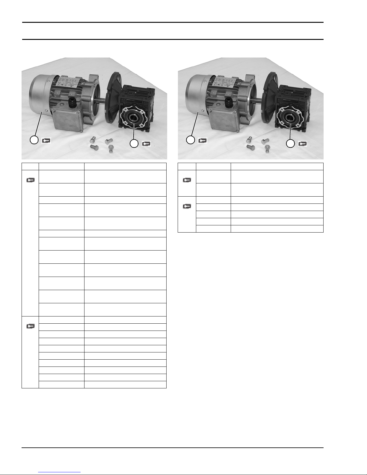
Service Parts
U.S. Version 90° Gearmotors CE Version 90° Gearmotors
1
Item Part Number Description
1 62MES411FN Motor, 0.25HP, (0.19 Kw), 115/230
Volts, 60 Hz, 1-Phase
62MES423FN Motor, 0.25HP, (0.19 Kw), 208-230/
460 Volts, 60 Hz, 3-Phase
62MSD3DEN Motor, 0.25HP, (0.19 Kw), 130 VDC
62MEH423FN Motor, 0.50HP, (0.37 Kw), 115/230
Volts, 60 Hz, 1-Phase
32MEH423FN Motor, 0.50HP, (0.37 Kw), 208-230/
460 Volts, 60 Hz, 3-Phase
62MHD9DEN Motor, 0.50HP, (0.37 Kw), 90 VDC
32MES423EN Motor, 0.50HP, (0.37 Kw), 230 Volts,
3-Phase Inverter Duty
62M060ESBDDEN Motor, 0.25HP, (0.19 Kw), 50 RPM,
Brushless DC
62M040ESBDDEN Motor, 0.25HP, (0.19 Kw), 75 RPM,
Brushless DC
62M020ESBDDEN Motor, 0.25HP, (0.19 Kw), 150 RPM,
Brushless DC
62M010ESBDDEN Motor, 0.25HP, (0.19 Kw), 300 RPM,
Brushless DC
62M005ESBDDEN Motor, 0.25HP, (0.19 Kw), 600 RPM,
Brushless DC
2 32M005EL Gear Reducer, 5:1, NEMA 42 CZ
32M010EL Gear Reducer, 10:1, NEMA 42 CZ
32M020EL Gear Reducer, 20:1, NEMA 42 CZ
32M040EL Gear Reducer, 40:1, NEMA 42 CZ
32M060EL Gear Reducer, 60:1, NEMA 42 CZ
32M005ES Gear Reducer, 5:1, 56C
32M010ES Gear Reducer, 10:1, 56C
32M020ES Gear Reducer, 20:1, 56C
32M040ES Gear Reducer, 40:1, 56C
32M060ES Gear Reducer, 60:1, 56C
2
1
Item Part Number Description
1 826-284 Motor, 0.19 Kw 230 Volts, 1400 RPM 50
Hz, 3-Phase
826-285 Motor, 0.19 Kw 230/400 Volts, 1400 RPM
50 Hz, 3-Phase
2 62Z005ES Gear Reducer, 5:1, 63 B5
62Z010ES Gear Reducer, 10:1, 63 B5
62Z020ES Gear Reducer, 20:1, 63 B5
62Z040ES Gear Reducer, 40:1, 63 B5
62Z060ES Gear Reducer, 60:1, 63 B5
2
2200 and 2300 Series Mid Mount Drive Package for Standard & Heavy Load Gearmotors
Dorner Mfg. Corp. 24 851-734 Rev. B
Page 25
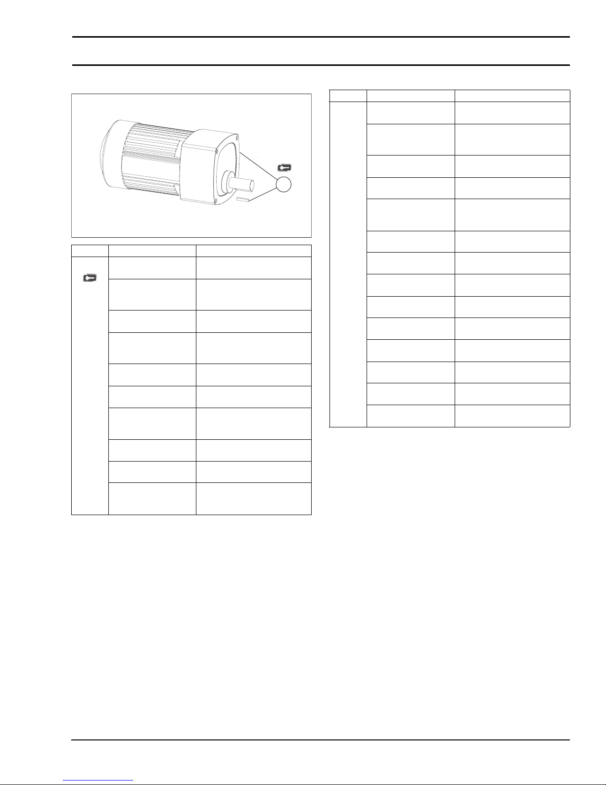
Parallel Shaft Gearmotors
Item Part No. Part Description
1 62M180PS411FN Motor, 0.08hp (0.06Kw), 10
RPM, 115VAC, 60Hz, 1-Phase
62M180PS411FR Motor, 0.08hp (0.06Kw), 10
RPM, 115VAC, 60Hz, 1-Phase
with reversing switch
62M060PS411FN Motor, 0.17hp (0.13Kw), 29
RPM, 115VAC, 60Hz, 1-Phase
62M060PS411FR Motor, 0.17hp (0.13Kw), 29
RPM, 115VAC, 60Hz, 1-Phase
with reversing switch
62M060PS423FN Motor, 0.25hp (0.19Kw), 29
RPM, 230VAC, 60Hz, 3-Phase
62M030PS411FN Motor, 0.17hp (0.13Kw), 58
RPM, 115VAC, 60Hz, 1-Phase
62M030PS411FR Motor, 0.17hp (0.13Kw), 58
RPM, 115VAC, 60Hz, 1-Phase
with reversing switch
62M030PS423FN Motor, 0.25hp (0.19Kw), 58
RPM, 230VAC, 60Hz, 3-Phase
62M020PS411FN Motor, 0.17hp (0.13Kw), 86
RPM, 230VAC, 60Hz, 1-Phase
62M020PS411FR Motor, 0.17hp (0.13Kw), 86
RPM, 115VAC, 60Hz, 1-Phase
with reversing switch
Service Parts
Item Part No. Part Description
62M010PS411FN Motor, 0.17hp (0.13Kw), 173
RPM, 115VAC, 60Hz, 1-Phase
62M010PS411FR Motor, 0.17hp (0.13Kw), 173
62M010PS423FN Motor, 0.25hp (0.19Kw), 173
1
62M005PS411FN Motor, 0.17hp (0.13Kw), 345
62M005PS411FR Motor, 0.17hp (0.13Kw), 345
62M180PSD3DEN Motor, 0.12hp (0.09Kw), 14
62M060PSD3DEN Motor, 0.25hp (0.19Kw), 42
62M030PSD3DEN Motor, 0.25hp (0.19Kw), 83
62M020PSD3DEN Motor, 0.25hp (0.19Kw), 125
62M010PSD3DEN Motor, 0.25hp (0.19Kw), 250
62M005PSD3DEN Motor, 0.25hp (0.19Kw), 500
62M050PSBDDEN Motor, 0.25hp (0.19Kw), 60
62M020PSBDDEN Motor, 0.25hp (0.19Kw), 150
62M010PSBDDEN Motor, 0.25hp (0.19Kw), 300
RPM, 115VAC, 60Hz, 1-P hase
with reversing switch
RPM, 230VAC, 60Hz, 3-Phase
RPM, 230VAC, 60Hz, 1-Phase
RPM, 115VAC, 60Hz, 1-P hase
with reversing switch
RPM, 130VDC
RPM, 130VDC
RPM, 130VDC
RPM, 130VDC
RPM, 130VDC
RPM, 130VDC
RPM, Brushless DC
RPM, Brushless DC
RPM, Brushless DC
2200 and 2300 Series Mid Mount Drive Package for Standard & Heavy Load Gearmotors
851-734 Rev. B 25 Dorner Mfg. Corp.
Page 26
Return Policy
Returns must have prior written factory authorization or they will not be accepted. Items that are returned to Dorner without
authorization will not be credited nor returned to the original sender. When calling for authorization, please have the
following information ready for the Dorner factory representative or your local distributor:
1. Name and address of customer.
2. Dorner part number(s) of item(s) being returned.
3. Reason for return.
4. Customer's original order number used when ordering the item(s).
5. Dorner or distributor invoice number (if available, part serial number).
A representative will discuss action to be taken on the returned items and provide a Returned Goods Authorization (RMA)
number for reference. RMA will automatically close 30 days after being issued. To get credit, items must be new and
undamaged. There will be a return charge on all items returned for credit, where Dorner was not at fault. It is the
customer’s responsibility to prevent damage during return shipping. Damaged or modified items will not be accepted. The
customer is responsible for return freight.
Conveyors and conveyor accessories
Standard catalog conveyors 30%
MPB, 7200, 7300 Series, cleated and specialty belt 50%
AquaGard & AquaPruf Series conveyors non-returnable items
Engineered to order products case by case
Drives and accessories 30%
Sanitary stand supports non-returnable items
Parts
Standard stock parts 30%
Plastic chain, cleated and specialty belts non-returnable items
Returns will not be accepted after 60 days from original invoice date. The return charge covers inspection, cleaning,
disassembly, disposal and reissuing of components to inventory. If a replacement is needed prior to evaluation of returned
item, a purchase order must be issued. Credit (if any) is issued only after return and evaluation is complete.
Dorner has representatives throughout the world. Contact Dorner for the name of your local representative. Our Customer
Service Team will gladly help with your questions on Dorner products.
For a copy of Dorner's Warranty, contact factory, distributor, service center or visit our website at www.dorner.com.
For replacement parts, contact an authorized Dorner Service Center or the factory.
Dorner Mfg. Corp. reserves the right to change
or discontinue products without notice. All
products and services are covered in
accordance with our standard warranty. All
rights reserved. © Dorner Mfg. Corp. 2012
851-734 Rev. B Printed in U.S.A.
DORNER MFG. CORP.
975 Cottonwood Ave., PO Box 20
Hartland, WI 53029-0020 USA
TEL 1-800-397-8664 (USA)
FAX 1-800-369-2440 (USA)
Internet: www.dorner.com
Outside the USA:
TEL 1-262-367-7600
FAX 1-262-367-5827
 Loading...