

Page 1
2200 Series
SmartFlex Conveyors
Installation, Maintenance & Parts Manual
DORNER MFG. CORP. INSIDE THE USA OUTSIDE THE USA
P.O. Box 20 • 975 Cottonwood Ave. TEL: 1-800-397-8664 TEL: 262-367-7600
Hartland, WI 53029-0020 USA FAX: 1-800-369-2440 FAX: 262-367-5827
For other service manuals visit our website at:
www.dorner.com/service_manuals.asp
851-757 Rev. A
Page 2

Table of Contents
Introduction ......................................................................... 3
Warnings - General Safety ................................................. 4
Produc t D es c r ip t io n ...... ............... .. ... .............. ... .. ................ 5
Specifications ...................................................................... 6
Modules: ........ ........................... ................... .................... 6
Conveyor Supports:............................... ........... .......... ..... 7
Maxim u m D is tances : .. ... .............. ... .. ...................... .. ... . 7
Specifications: .............................................................. 7
Table 1: Gearmotor Specifications .................................. 7
U.S. Version ................................................................. 7
CE Version ................................................................... 7
SEW Gearmotor Specifications ................................... 8
Table 2: Belt Speed for Stan dard Load
Fixed Sp eed 9 0° G ear m o to r s . .. ...................... .. ... ............. 8
U.S. Version (60 Hz Gearmotors)................................ 8
CE Version (50 H z G ea rmotors )......... .. ............... .. .. .... 8
Table 3: Belt Speeds f or Standard Load
Variable Speed 90° DC Gearmotors................................ 8
U.S. Version (60 Hz Gearmotors)................................ 8
Table 4: Belt Speeds f or Standard Load
Variable Speed 90° VFD Gearmotors ............................. 9
U.S. Version (60 Hz Gearmotors)................................ 9
CE Version (50 H z G ea rmotors )......... .. ............... .. .. .... 9
Table 5: Belt Speeds for Standard Load SEW
Fixed Sp eed G earmoto r s............... .. ... ...................... .. .. .... 9
Table 6: Belt Speeds for Standard Load SEW
Variable Speed Gearmotors ............................................. 9
Table 7: Belt Speed for Heavy Load
Fixed Sp eed 9 0° G ear m o to r s . .. ...................... .. ... ............. 9
U.S. Version (60 Hz Gearmotors)................................ 9
Table 8: Belt Speed for Heavy Load
Variable Speed 90° VFD Gearmotors ........................... 10
U.S. Version (60 Hz Gearmotors).............................. 10
Table 9: Belt Speeds for Heavy Load
SEW Fix e d S p ee d Ge ar mo t o rs ....... ... ....... .. ... .. ........ .. .. .. 10
Table 10: Belt Speeds for Heavy Load
SEW V ar i ab le S pe ed G ea rmotor .. .. ...................... ... .. .... 10
Install at i on . ............... .. .. ...................... ... .. ...................... .. .. 11
Required Tools............................................................... 11
Recom mended Ins t al l at io n Se q u en ce .. ....... ... .. .............. 11
Module Lengths Longer Than 10 ft (3048 m m)............ 11
Knuck l es ..... .. ........ .. .. ...................... ... .. ...................... .. .. 12
Curv es ......... .. ... ...................... .. .. ...................... ... .. ......... 12
Tails .. .. ... ............... .. .. ...................... ... .. ...................... .. .. 13
Unroll Wear Strips......................................................... 13
Mounting Bracket s.......................................... ............... 14
Instal l S u p po rt Stands .. .. ... ....... .. ... ...................... .. ... ...... 14
Belt Installation.............................................................. 14
Weigh t ed Ta ke - U p.. .. .............................. .. .. ................... 16
Instal l G u id i ng . .. ... .............. ... .. ............... .. .. ................... 17
Standard 1.5” Guiding................................................ 17
Fully Adjustable Guiding........................................... 18
Instal l D r iv e Pa ck ag e ................. ... .. ............... .. ... ........... 20
Preventive Maintenance and Adjustment.......................... 21
Required Tools............................................................... 21
Checklist ....................................................................... 21
Lubri ca ti o n............................... .. ... .............. ... .. .............. 21
Maintaining the Conveyor Belt...... ........ ........................ 21
Troubleshooting ......................................................... 21
Conveyor Belt Replacement...... ........ ................. .......... 21
Replacing a Section of Belt........................................ 21
Replacing the Entire Belt ........................................... 22
Conveyor Belt Tensioning.............................................. 22
Wear Strip Removal ....................................................... 23
Wear Strip Installation.................................................... 23
Attaching Wear Strip on Straight Frame .................... 23
Attaching Wear Strip on Conveyor Frame ................. 24
Attaching Wear Strip at Wheel Bend ......................... 25
Attaching Wear Strip .................................................. 25
Idler Pu ll ey A ss e m b ly ..................... .. ... ...................... .. .. 26
Drive Spindle Shaft Assembly ....................................... 27
Retaining Guide Replacement........................................ 28
Driv e En d.......... .. ... .............. ... .. ... ....... ... .. ................... 28
Idler End ..................................................................... 29
Curve Assembly ............................................................. 30
Weighted Take-Up ......................................................... 30
Power Tr an sf e r ....... ... .. ...................... ... .. ... ....... .. ... ......... 32
Removal...................................................................... 32
Installation .................................................................. 36
Roller Transfer ............................................................... 39
Serv ic e P arts . .. ........ .. .. ............... .. ... ...................... .. ... ......... 40
Drive Tail ....................................................................... 40
Weighted Take-Up ......................................................... 42
Weigh te d Tak e- U p D ri v e Ta il. ...................... ... .. ............ 44
Idler Ta il ..... ... .............. ... .. ...................... ... .. ................... 45
Frame A ss e m b ly........ .. ... ....... .. ... ...................... .. ... ......... 46
Wear Str i p R ep la cemen t To o l .... .. ............... .. ... .............. 47
65 Width Curve Frame Assembly.................................. 48
105 Width Curve Frame Assembly ................................ 49
150 Width Curve Frame Assembly ................................ 50
65 Width Kn u c kl e Fr ame Asse m b ly ............................ .. 51
105 Widt h Kn u ck l e Fr ame Assembly .. .............. ... .. ....... 52
150 Widt h Kn u ck l e Fr ame Assembly .. .............. ... .. ....... 53
04 3" High Sides for Straight Modules .......................... 54
04 3" High Sides for Curve Modules ............................. 55
04 3" High Sides for Incline/Decline Modules .............. 56
05 1.50 " Hi g h Si de s for S traight M o du l es .... ... ....... ... .. .. 57
05 1.50" Hi g h Si de s for Cu r ve Module s ....... ... .. ............ 58
05 1.50" High Sides for Incline/Decline Modules ......... 59
13 Fully Adjustabl e Guiding for Straight Modules........ 60
13 Fully Adjustable Guiding for Curve Modules........... 61
14 Tool-Less Fully Adjustable Guiding
for Straight Modules...... ......................................... .. ...... 62
14 Tool-Less Fully Adjustable Guiding
for Curve Modules.......................................................... 63
16 Gull Wing Guiding for Straight Modules.................. 64
16 Gull Wing Guiding for Curve Modules ................. .. . 65
#13 & #14 - Adjustable Guiding and #16 - Gull
Wing Gu id i ng f or I nc li n e/ D ecline M o dules..... .. ............ 66
Power Tr an sf e r ....... ... .. ...................... ... .. ... ....... .. ... ......... 67
Transfer Roller ............................................................... 68
Transfer Roller to 2200 Series Conveyor....................... 69
Mount in g Brackets ......... .............. ... .. ............... .. ... ......... 70
Motor Mounting Assem bly............................................ 71
Connecting Assembly..................................................... 72
Gearmotor Mounting Package........................................ 73
SEW Gearmotor Mounting Package .............................. 74
90° SEW G earmot ors .. ... ....... .. ... ...................... .. ... ......... 75
90° Industrial Gearmotors.............................................. 75
Ordering a Replacement Chain ...................................... 76
Belt Removal Tool ......................................................... 76
Notes .................................................................................. 77
Return Policy...................................................................... 78
Dorner Mfg. Corp. 2 851-757 Rev. A
2200 Series SmartFlex Conveyors
Page 3
IMPORTANT
Some illustrations may show guards
removed. DO NOT operate equipment
without guards.
Upon receipt of shipment:
• Compare shipment with packing slip. Contact factory
regarding discrepancies.
• Inspect packages for shipping damage. Contact carrier
regarding damage.
• Accessories ma y be shipped loose. See acce ssory instructions for installation.
Dorner’s Limi ted Warranty applies.
Introduction
Dorner has convenient, pre-configur ed kit s of K ey Serv ice
Parts for all conveyor produc ts. These time saving kit s are
easy to order, designed for fast installation, and guarantee
you will have what you need when you need it. Key Parts
and Kits are marked in the Service Parts section of this
manual with the Performance Parts Kits logo .
Dorner reserves the right to make changes at any time
without notice or obligation.
851-757 Rev. A 3 Dorner Mfg. Corp.
2200 Series SmartFlex Conveyors
Page 4
Warnings - General Safety
A
A
A
A
A
A
A
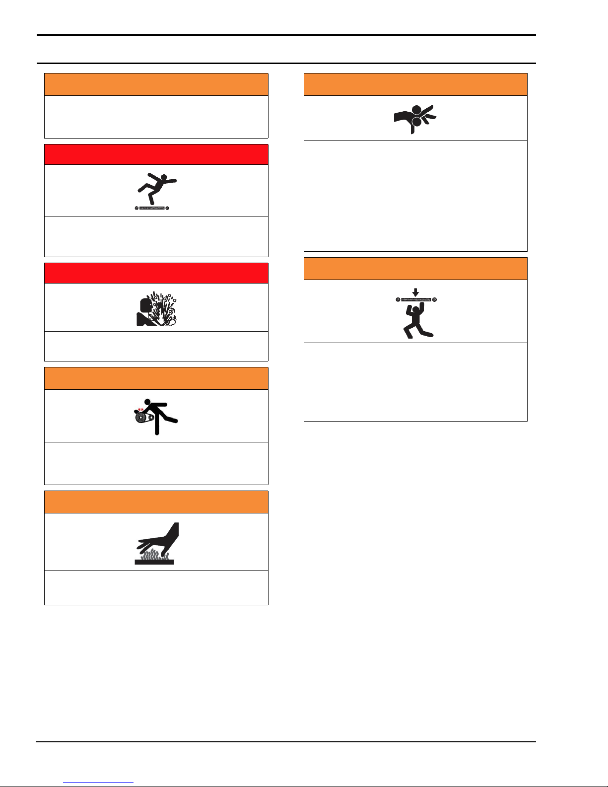
WARNING
The safety alert symbol, black triangle with
white exclamation, is used to alert you to
potential personal injury hazards.
DANGER
Climbing, sitting, walking or riding on
conveyor will cause severe injury. KEEP OFF
CONVEYORS.
DANGER
DO NOT OPERATE CONVEYORS IN AN
EXPLOSIVE ENVIRONMENT.
WARNING
WARNING
Dorner cannot control the physical
installation and application of conveyors.
Taking protective measures is the
responsibility of the user.
When conveyors are used in conjunction
with other equipment or as part of a multiple
conveyor system, CHECK FOR POTENTIAL
PINCH POINTS and other mechanical
hazards before system start-up.
WARNING
Loosening stand height or angle adjustment
screws may cause conveyor sections to drop
down, causing severe injury.
SUPPORT CONVEYOR SECTIONS PRIOR TO
LOOSENING STAND HEIGHT OR ANGLE
ADJUSTMENT SCREWS.
Exposed moving parts can cause severe
injury. LOCK OUT POWER before removing
guards or performing maintenance.
WARNING
Gearmotors may be HOT.
DO NOT TOUCH Gearmotors.
Dorner Mfg. Corp. 4 851-757 Rev. A
2200 Series SmartFlex Conveyors
Page 5
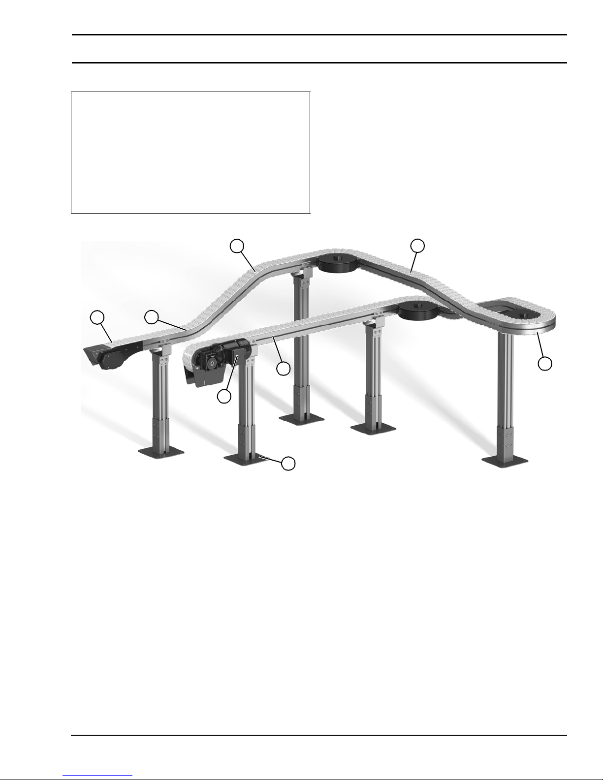
Refer to Figure 1 for typical components.
1 Infeed Module
2 Curve Module
3 Incline Module
4 Decline Module
5 Intermediate Module
6 Drive Module
7 Gearmotor
8 Stands
Figure 1
Product Description
4
1
3
6
7
8
5
2
Figure 1
851-757 Rev. A 5 Dorner Mfg. Corp.
2200 Series SmartFlex Conveyors
Page 6
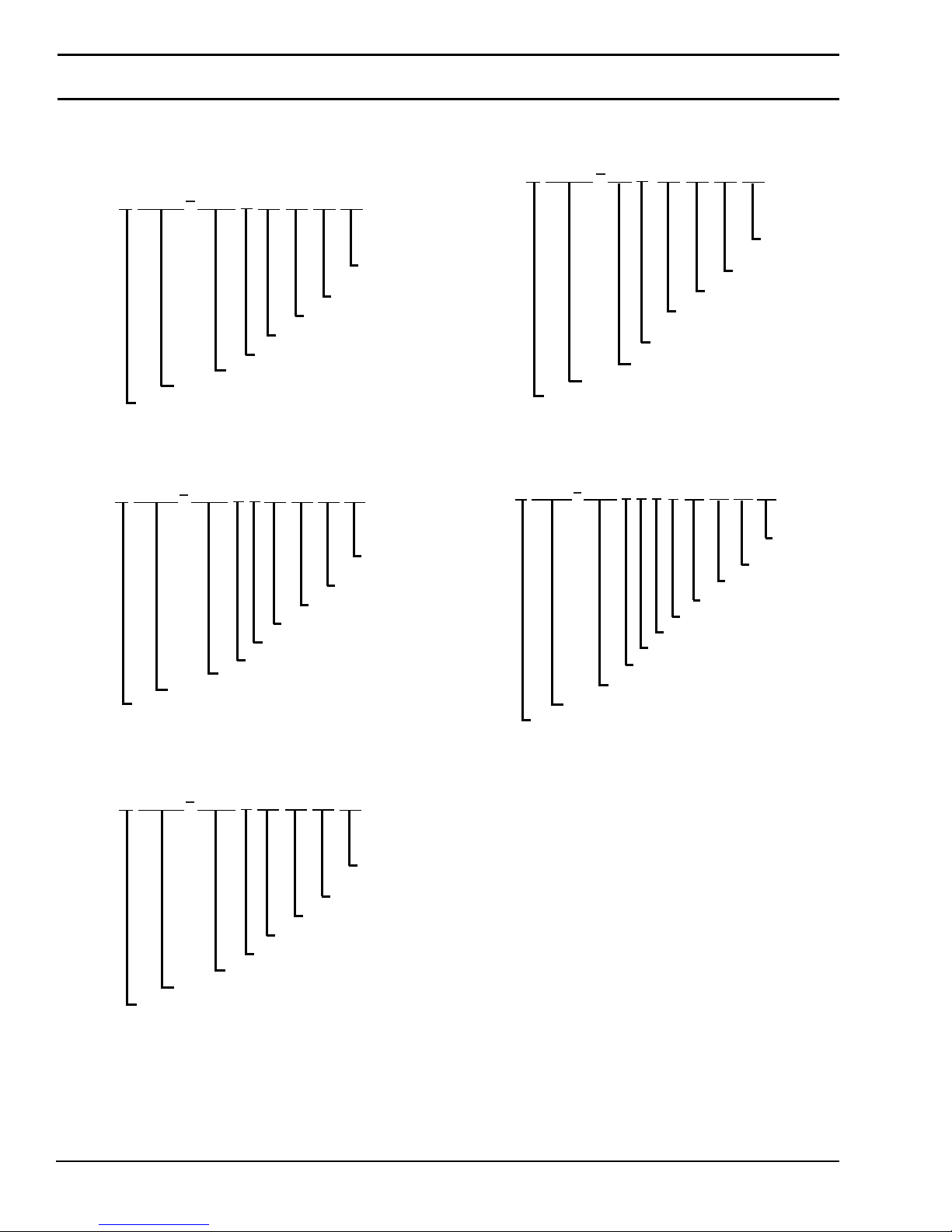
Specifications
Modules:
Infeed Module
22SF 1
Curve Module
22SF 2
WWW
M
Document Language
WWW
M
Document Language
I
LLLL
Convey or Width
AAA
Convey or Width
PP
Idler T ail Type
Module Length
T
D
Curve T ype
Angle
PP
BB
Profile D Side
Profile A Side
PP
PP
Direction
BB
Profile D Side
Profile A Side
SS
Sequence
Number
Belt T ype
SS
Sequence
Number
Belt T ype
Incline/Decline Module
22SF 4
WWW
M
Convey or Width
Document Language
AA
U
Angle
Drive Module
22SF 5
WWW
M
Conveyor Width
Document Language
DPT
LLLL
Drive T ail Type
Conveyor Length
PP
PP
Knuckle Type
Shaft Position
BB
SS
Sequence
Number
Belt T ype
Profile D Side
Profile A Side
PP
PP
M
Motor Code
Weighted Take-Up Location
BB
SS
Belt T ype
Profile D Side
Profile A Side
Sequence
Number
Intermediate Module
22SF 3
WWW
M
Convey or Width
Document Language
Dorner Mfg. Corp. 6 851-757 Rev. A
I
LLLL
Module Length
PP
PP
Idler T ail Type
BB
Profile D Side
Profile A Side
SS
Sequence
Number
Belt T ype
2200 Series SmartFlex Conveyors
Page 7
Specifications
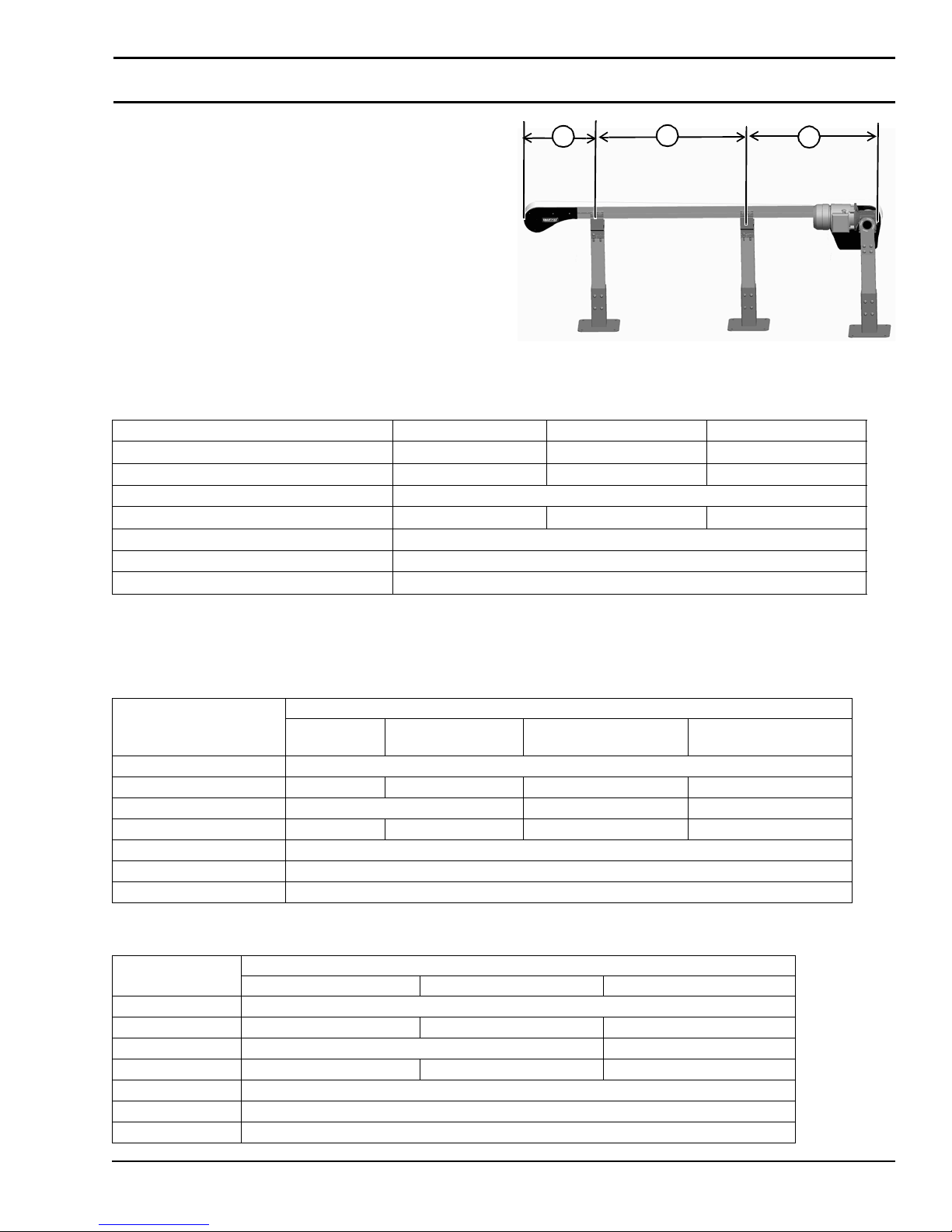
Conveyor Supports:
Maximum Distances:
1 = 36” (914 mm)
2 = 10 ft (3048 mm)*
3 = 36
” (914 mm)
* For conveyors longer than 10 ft (3048 mm), insta ll suppo rt
at joint.
Note: Additional support required on 180° curve modules.
Specifications:
Conveyor Widths Reference (WW) 065 105 150
Conveyor Belt Width 2.47” (63 mm) 4.05” (103 mm) 5.91” (150 mm)
Maximum Load 330 lb (149 kg) 660 lb (299 kg) 660 lb (299 kg)
Maximum Belt Speed 250 RPM
Belt Takeup (Standard Weighted Take-up) 6” / 8” (152 mm / 203 mm) 6” / 8” (152 mm / 203 mm) 6” / 8” (152 mm / 203 mm)
Module Length Reference 0167-5000
Module Length 1.67' (509 mm)- 50.00' (15,240 mm)
Total Conveyor Length 99 ft (30,175 mm) maximum
Figure 2
1
2
3
Figure 2
Table 1: Gearmotor Specifications
U.S. Version
Standard Load Gearmotor
Item
Output Power 0.5 hp (0.37 kw)
Input Voltage 115 VAC 208 – 230/460 VAC 230 VAC 90VDC
Input Frequency 60Hz 10 – 60Hz N/A
Input Current (Amperes) 7.4 2.1 – 2/1 1.6 5.0
Gearmotor Ratios 5:1, 10:1, 20:1
Frame Size NEMA 56C
Motor Type Totally enclosed, Fan cooled
CE Version
Item
Output Power 0.37 kW
Input Voltage 230 VAC 230/400 VAC 230 VAC
Input Frequency 50 Hz 25 to 63 Hz
Input Current 2.6 Amperes 2.1/1.2 Amperes 2.1Amperes
Gearmotor Ratios 5:1, 10:1, 20:1
Protection Rating IP55
Frame Size IEC 71 B5
Single-
Phase
Single Phase Three Phase VFD Variable Speed
Three Phase VFD Variable Speed DC Variable Speed
Standard Load Gearmotor
851-757 Rev. A 7 Dorner Mfg. Corp.
2200 Series SmartFlex Conveyors
Page 8
Specifications
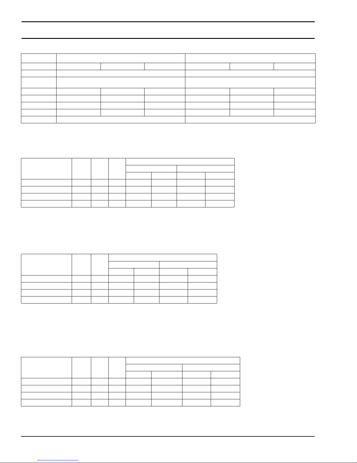
SEW Gearmotor Specifications
Three Phase VFD Vari Speed
Output Power 0.5 Hp (0.37 kW) 0.75 Hp (0.56 kW) 1 Hp (0.75 kW) 0.5 Hp (0.37 kW) 0.75 Hp (0.56 kW) 1 Hp (0.75 kW)
Input Voltage 230/460 230/460
Input
Frequency
Input Current 1.84/0.92 2.50/1.25 2.90/1.44 1.84/0.92 2.50/1.25 2.90/1.44
RPM 47 134 264 8 to 47 22 to 134 44 to 264
Ratio 37.7:1 13.4:1 6.8:1 37.7:1 13.4:1 6.8:1
Motor Frame IEC71
Motor Type IP54 Totally Enclosed Fan Cooled IP54 Totally Enclosed Fan Cooled
Table 2: Belt Speed for Standard Load Fixed Speed 90° Gearmotors
U.S. Version (60 Hz Gearmotors)
Part Number RPM In-lb N-m
32M060ES4(vp)FN 29 226 25.5 38 11.6 40 12.2
32M040ES4(vp)FN 43 247 27.9 58 17.7 60 18.3
32M020ES4(vp)FN 86 248 27.9 115 35.1 121 36.9
32M010ES4(vp)FN 173 156 17.6 230 70.1 241 73.5
(vp) = voltage and phase
11 = 115 V, 1-phase
23 = 208 – 230/460 V, 3-phase
60 Hz 10 to 60 Hz
IEC71 IEC80
Belt Speed
65 mm 105 mm & 150mm
Ft/min M/min Ft/min M/min
IEC71
IEC71 IEC80
CE Version (50 Hz Gearmotors)
Belt Speed
Part Number RPM N-m
62Z060ES4(vp)FN 23 26.8 31 9.4 33 10.1
62Z040ES4(vp)FN 35 29.4 47 14.3 49 14.9
32Z020ES4(vp)FN 70 29.9 93 28.3 98 29.9
32Z010ES4(vp)FN 140 21.5 187 57.0 196 59.7
(vp) = voltage and phase
21 = 230 V, 1-phase
65 mm 105 mm & 150 mm
Ft/min M/min Ft/min M/min
23 = 230 V, 3-phase
43 = 400 V, 3-phase
Table 3: Belt Speeds for Standard Load Variable Speed 90° DC Gearmotors
U.S. Version (60 Hz Gearmotors)
Belt Speed
Part Number RPM In-lb N-m
32M060ESD9DEN 42 198 22.4 6.8 - 56 2.1 - 17.1 7.0 - 58 2.1 - 17.7
32M040ESD9DEN 63 215 24.3 10 - 83 3.0 - 25.3 11 - 87 3.3 - 26.5
62M020ESD9DEN 125 196 22.1 20 - 167 6.1 - 50.9 21 - 175 6.4 - 53.3
62M010ESD9DEN 250 108 12.2 40 - 333 12.2 - 76.2 42 - 349 12.8 - 76.2
65 mm 105 mm & 150 mm
Ft/min M/min Ft/min M/min
Dorner Mfg. Corp. 8 851-757 Rev. A
2200 Series SmartFlex Conveyors
Page 9
Specifications
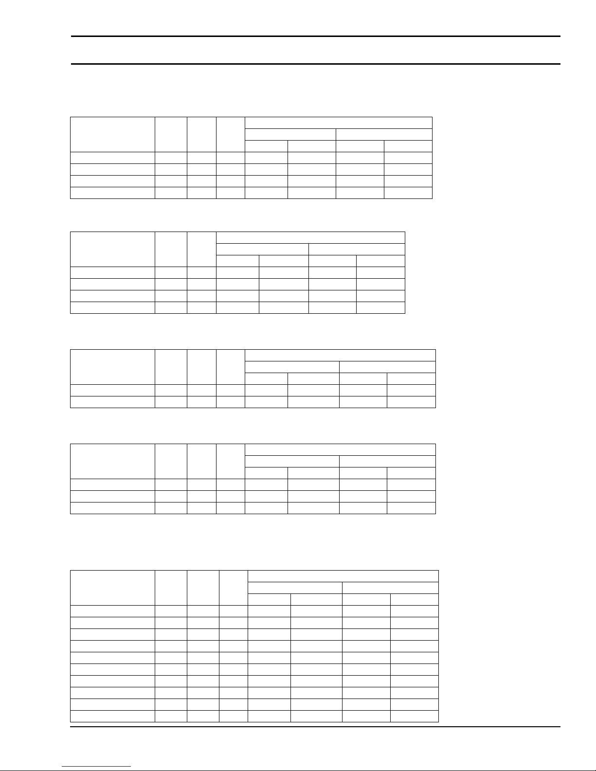
Table 4: Belt Speeds for Standard Load Variable Speed 90° VFD Gearmotors
U.S. Version (60 Hz Gearmotors)
Belt Speed
Part Number RPM In-lb N-m
32M060ES423EN 29 226 25.5 3.8 - 38 1.2 - 11.6 4.0 - 40 1.2 - 12.2
32M040ES423EN 43 247 27.9 5.8 - 58 1.8 - 17.7 6.0 - 60 1.8 - 18.3
32M020ES423EN 86 248 27.9 12 -115 3.7 - 35.1 12 - 121 3.7 - 36.9
32M010ES423EN 173 156 17.6 23 - 230 7.0 - 70.1 24 - 241 7.3 - 73.5
CE Version (50 Hz Gearmotors)
Part Number RPM N-m
Ft/min M/min Ft/min M/min
62Z060ES423EN 23 26.8 16 - 39 4.9 - 11.9 17 - 42 5.2 - 12.8
62Z040ES423EN 35 29.4 24 - 59 7.3 - 18.0 25 - 62 7.6 - 18.9
32Z020ES423EN 70 29.9 47 -117 14.3 - 35.7 49 - 123 14.9 - 37.5
32Z010ES423EN 140 21.5 94 - 236 28.7 - 71.9 98 - 247 29.9 - 75.3
Table 5: Belt Speeds for Standard Load SEW Fixed Speed Gearmotors
65 mm 105 mm & 150mm
Ft/min M/min Ft/min M/min
Belt Speed
65 mm 105 mm & 150mm
Belt Speed
Part Number RPM In-lb N-m
32M038WS423EN 47 548 61.9 63 19.2 66 20.1
32M013WS423EN 134 327 37.0 179 54.6 187 57.0
65 mm 105 mm & 150 mm
Ft/min M/min Ft/min M/min
Table 6: Belt Speeds for Standard Load SEW Variable Speed Gearmotors
Belt Speed
Part Number RPM In-lb N-m
32M038WS423EN 47 548 61.9 6.3 - 63 1.9 - 19.2 6.6 - 66 2.0 - 20.1
32M013WS423EN 134 327 37.0 18 - 179 5.5 - 54.6 19 - 187 5.8 - 57.0
32M007WS423EN 264 221 25.0 35 - 352 10.7 - 76.2 37- 369 11.3 - 76.2
65 mm 105 mm & 150 mm
Ft/min M/min Ft/min M/min
Table 7: Belt Speed for Heavy Load Fixed Speed 90° Gearmotors
U.S. Version (60 Hz Gearmotors)
Belt Speed
Part Number RPM In-lb N-m
32M100EH4(vp)FN 17 913 103 23 7.0 24 7.3
32M080EH4(vp)FN 22 833 94 29 8.8 31 9.4
32M060EH4(vp)FN 29 680 76 39 11.9 41 12.5
32M050EH423FN 35 1206 136 47 14.3 49 14.9
32M040EH423FN 43 1023 115 57 17.4 60 18.3
32M030EH423FN 58 1217 137 77 23.5 81 24.7
32M025EH423FN 69 1069 121 92 28.0 96 29.3
32M020EH423FN 86 1184 134 115 35.1 120 36.6
32M015EH423FN 115 910 103 153 46.6 161 49.1
32M010EH423FN 173 636 72 231 70.4 242 73.8
65 mm 105 mm & 150 mm
Ft/min M/min Ft/min M/min
851-757 Rev. A 9 Dorner Mfg. Corp.
2200 Series SmartFlex Conveyors
Page 10
Specifications
Table 8: Belt Speed for Heavy Load Variable Speed 90° VFD Gearmotors
U.S. Version (60 Hz Gearmotors)
Belt Speed
Part Number RPM In-lb N-m
32M100HH423EN 17 913 103 2.3 - 23 0.7 - 7.0 2.4 - 24 0.7 - 7.3
32M080HH423EN 22 833 94 2.9 - 29 0.9 - 8.8 3.1 - 31 0.9 - 9.4
32M060HH423EN 29 680 76 3.9 - 39 1.2 - 11.9 4.1 - 41 1.2 - 12.5
32M050HH423EN 35 1206 136 4.7 - 47 1.4 - 14.3 4.9 - 49 1.5 - 14.9
32M040HH423EN 43 1023 115 5.7 - 57 1.7 - 17.4 6.0 - 60 1.8 - 18.3
32M030HH423EN 58 1217 137 7.7 - 77 2.3 - 23.5 8.1 - 81 2.5 - 24.7
32M025HH423EN 69 1069 121 9.2 - 92 2.8 - 28.0 9.6 - 96 2.9 - 29.3
32M020HH423EN 86 1184 134 12 - 115 3.7 - 35.1 12 - 120 3.7 - 36.6
32M015HH423EN 115 910 103 15 - 153 4.6 - 46.6 16 - 161 4.9 - 49.1
32M010HH423EN 173 636 72 23 - 231 7.0 - 70.4 24 - 242 7.3 - 73.8
Table 9: Belt Speeds for Heavy Load SEW Fixed Speed Gearmotors
Part Number RPM In-lb N-m
32M128WH423EN 13 991 112.0 17 5.2 18 5.5
32M044WH423EN 38 973 109.9 51 15.5 53 16.2
32M016WH423EN 106 787 88.9 141 43.0 148 45.1
32M008WH423EN 201 575 65.0 268 81.7 281 85.6
65 mm 105 mm & 150 mm
Ft/min M/min Ft/min M/min
Belt Speed
65 mm 105 mm & 150 mm
Ft/min M/min Ft/min M/min
Table 10: Belt Speeds for Heavy Load SEW Variable Speed Gearmotor
Belt Speed
Part Number RPM In-lb N-m
32M128WH423EN 13 991 112.0 1.7 - 17 0.5 - 5.2 1.8 - 18 0.5 - 5.5
32M044WH423EN 38 973 109.9 5.1 - 51 1.6 - 15.5 5.3 - 53 1.6 - 16.2
32M016WH423EN 106 787 88.9 14 - 141 4.3 - 43.0 15 - 148 4.6 - 45.1
32M008WH423EN 201 575 65.0 27 - 268 8.2 - 81.7 28 - 281 8.5 - 85.6
65 mm 105 mm & 150 mm
Ft/min M/min Ft/min M/min
Dorner Mfg. Corp. 10 851-757 Rev. A
2200 Series SmartFlex Conveyors
Page 11
Installation
Required Tools
• 3/32” hex wrench
• 3 mm hex wrench
• 4 mm hex wrench
• 5 mm hex wrench
• 6 mm hex wrench
• 8 mm hex wrench
• 10 mm wrench
• 13 mm wrench
• 16 mm wrench
• Belt Removal Tool #203480
Recommended Installation
Sequence
• Locate and arrange secti ons by section labels:
• Assemble conveyor (Module lengths longer than 10 ft
(3000 mm)”)
• Install knuckles
• Install curves
• Install tails
• Unroll wear strips
• Install mounting bracket
• Install support stands
• Install belt
• Install weighted take-up
• Install guiding
• Install drive package
- Motor mounting package
- Gearmotor
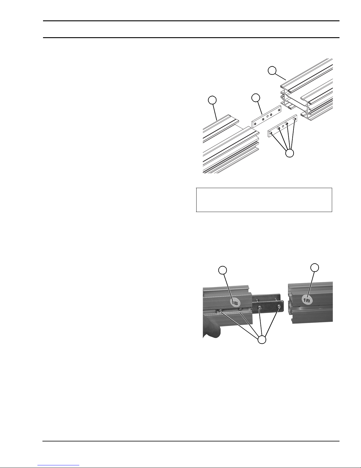
Typical Connecting Components (Figur e 3)
Figure 3
2
2
1
3
Figure 3
1Clamp Plate
2 Conveyor frames
3 Set Screw, M8 - 1.25 x 10 mm
Module Lengths Longer Than 10 ft
(3048 mm)
1. Locate and arrange conveyor sections by section labels
(Figu re 4 , item 1).
Figure 4
1
1
851-757 Rev. A 11 Dorner Mfg. Corp.
2
Figure 4
2. Join both conveyor sections, and tighten two set screws
(Figu re 4 , item 2) on both sides. Tig hten al l s et screws
1/4 turn past contact with frame.
2200 Series SmartFlex Conveyors
Page 12
Installation
Knuckles
NOTE
Be sure all frame sections
properly supported during knuckle assembly.
Figure 5
1
Figure 5
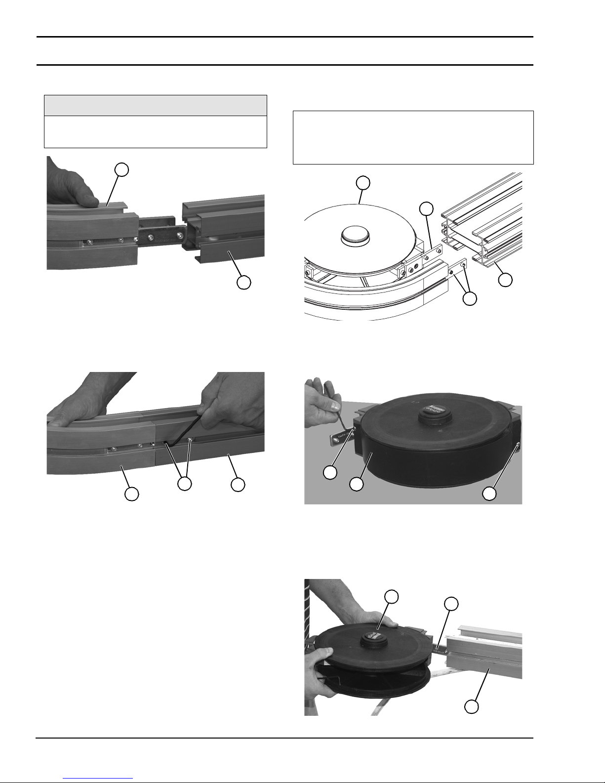
1. Join knuckle conveyor frame s ection (Figure 6, item 1),
and conveyor frame (Figure 6 , item 2) and secure with
two set screws (Figure 6, item 3) on both sides. T ighte n
all set s cr e w s 1/ 4 tu r n pa s t co n t ac t w ith fram e .
Figure 6
(Figure 5, item
1) are
1
Curves
Typical Curve Connecting Componen ts (Figure 7)
1Clamp Plate
2 Conveyor Frames
3 Curve Assembly
4 Set Screw, M8 - 1.25 x 10 mm
Figure 7
3
1
2
4
Figure 7
1. Remove two screws (Figure 8, item 1) and guard
(Figu re 8 , item 2) from curve assembly.
Figure 8
3
1
Figure 6
Dorner Mfg. Corp. 12 851-757 Rev. A
1
2
2. In st al l cu r v e assembl y (Fig u re 9, it em 1) clamp plates
(Figu re 9 , item 2) into one conveyor section (Figure
9, item 3) by lining up cl amp plat e with s lot in co nveyor
frame.
Figure 9
2200 Series SmartFlex Conveyors
2
1
Figure 8
1
2
3
Figure 9
Page 13
Installation
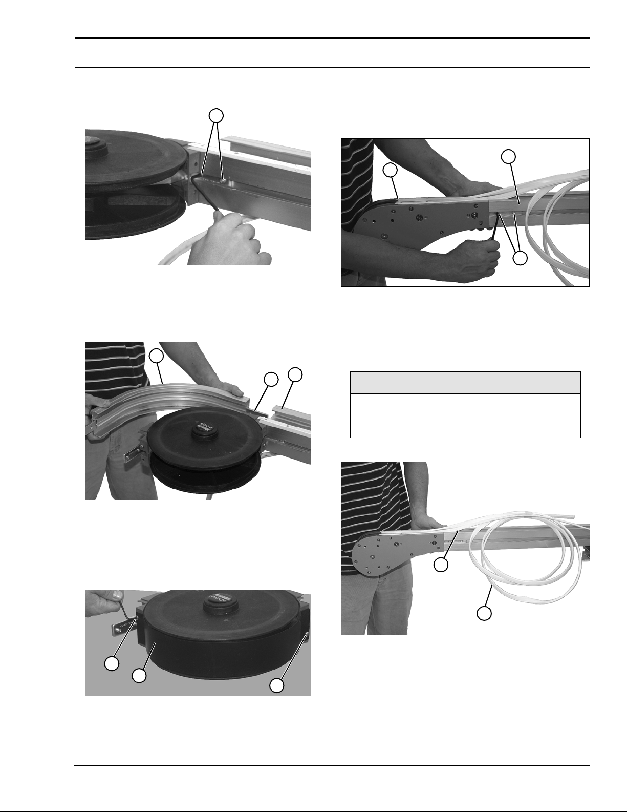
3. Secure with two se t screws (Figure 10, item 1). Tighten
all set s cr e w s 1/ 4 tu r n pa s t co n t ac t w ith fram e .
Figure 10
1
Figure 10
4. Inst all outer curve fra me assembly (Figure 11, item 1)
clamp plate (Fig ure 11, item 2) into conveyor frame
section (Figure 11, item 3) by lining up clamp plate
with slot in conveyor frame.
Figure 11
1
3
2
Tails
1. In s t al l tail assembl y (Figure 13, item 1) clamp plate
into conveyor frame sect ion ( Figur e 9, item 2) by lining
up clamp plate with slot in conveyor frame.
Figure 13
2
1
3
Figure 13
2. Secure with two set sc rews (Figure 13, item 3). Tight en
all set screws 1/4 turn pas t contact with frame.
Unroll Wear Strips
NOTE
Figure 11
5. Install opposite end of conveyor onto curve assembly,
repeating pr oce dure. Tighten all set screws 1/4 turn past
contact wi th frame.
6. Install guard with (F igu re 12, item 1) two screws
(Figure 12, item 2).
Figure 12
2
1
2
Top and bottom wear strips are shipped
pinned/attached at various places on
conveyor.
1. Unroll wear strip (Figure 14, item 1).
Figure 14
2
1
Figure 14
2. Guide wear strip into channel (Fi gu re 14, item 2) on
conveyor frame.
Figure 12
851-757 Rev. A 13 Dorner Mfg. Corp.
2200 Series SmartFlex Conveyors
Page 14
Installation
Mounting Brackets
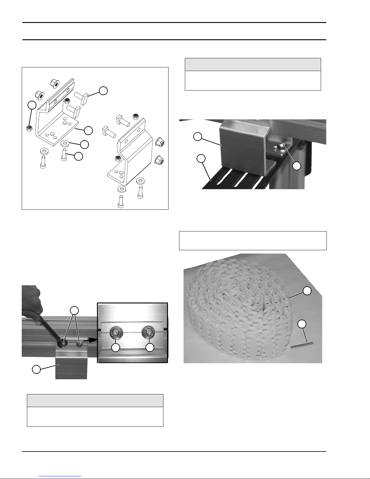
1. Locate bracke ts. Exploded views shown in Figure 15.
Figure 15
5
1
4
2
3
Figure 15
2. Remove nuts (Figure 15, item 1), washers (Figure
15, item 2), and screws (Figure 15 , ite m 3 ) from
brackets (F igu re 15, item 4).
3. Insert bracket wit h st uds (Figure 15, item 5) with head
parallel to slot into conveyor side slots.
4. Fasten brackets (Figure 16,item 1) to conveyor with
nuts (Figure 16, item 2) on studs. Turn nuts clockwis e
to rotate studs in side slots.
Figure 16
Install Support Stands
NOTE
For detailed assembly instructions, please
see your appropriate support stand manual.
1. Fasten brackets (Figure 1 7,item 1) to support stand
(Figure 17, item 2) with m ountin g s crews, was hers, and
nuts (Figure 17, item 3).
Figure 17
1
2
3
Figure 17
Belt Installation
Ty pical Belt Components (Figure 18).
1 Chain Belt
2 Belt Rod
Figure 18
1
2
3
1
Figure 16
NOTE
Be certain that stud slot (Figure 16, item 3) is
close to vertical when finished tightening nut.
5. Tighten nuts (Figure 16, item 2).
Dorner Mfg. Corp. 14 851-757 Rev. A
2
3
Figure 18
1. Position the belt on the conveyor frame.
2200 Series SmartFlex Conveyors
Page 15
Installation
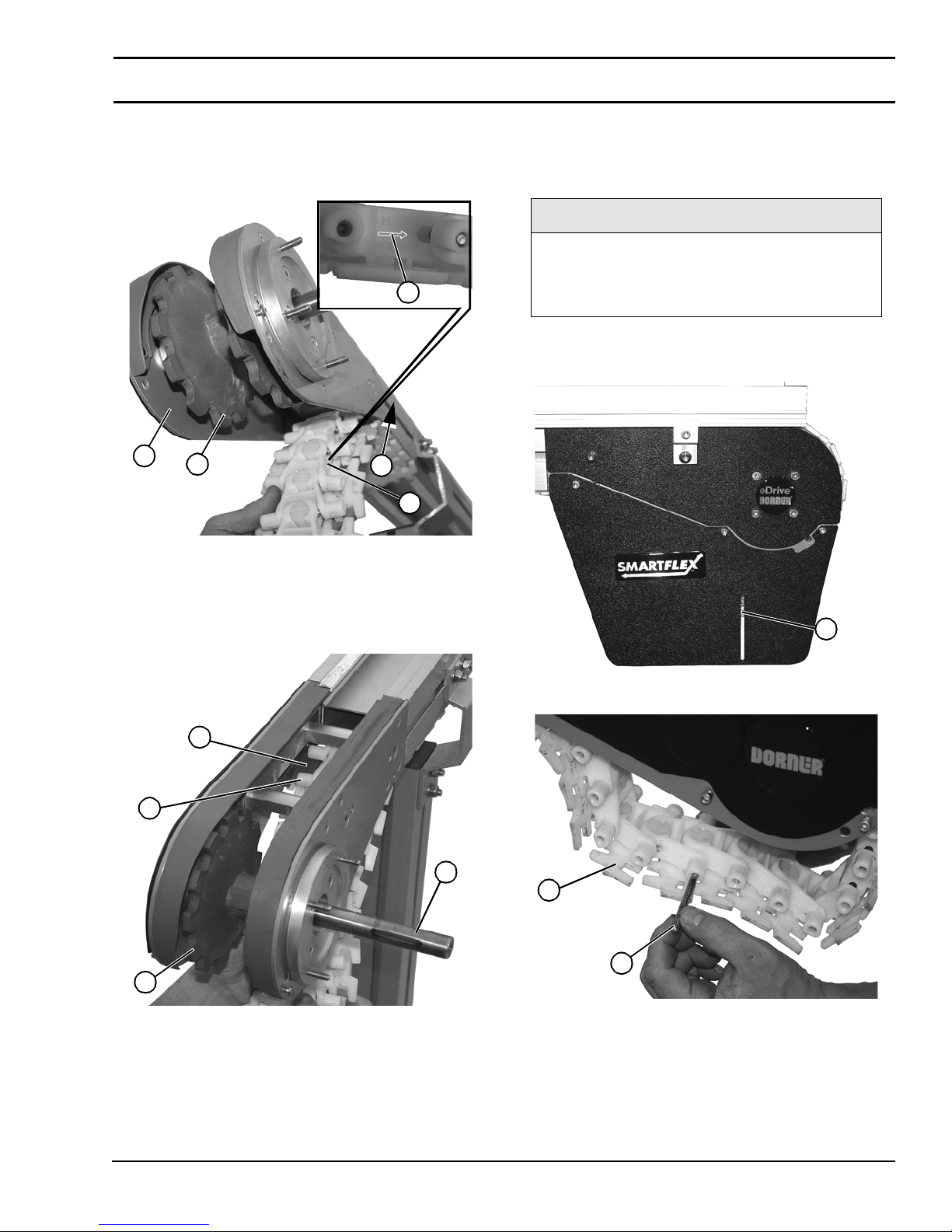
2. Install the bel t with direction arrow (Figure 19, item 1)
pointing in direction of belt travel (Figure 19, item 2).
Install belt from under tail end (Figure 19, item 3) and
onto cogs (Figur e 19, item 4)of shaft.
Figure 19
1
3
4
2
1
Figure 19
Standard Tail
• Install belt around drive end of conveyor and bring the
ends of the belt (Figure 22, item 1) together.
• Insert rod (Figu re 2 2 , item 2 ).
NOTE
Before inserting belt rod to connect belt ends,
be certain that the slack on belt is showing in
slotted area (Figure 21, item 1) on conveyor
drive end.
• Use punch and hammer or belt removal tool #203480 to
press pin just below flush with side of belt. Stop when pin
detent is felt.
Figure 21
3. Continue wrapping belt (Figure 20, item 1) on top of
idler t ail re ta ining gu ide (Figure 20, item 2), continuing
to turn sh a ft (Figure 20, item 3) to guide belt around
cogs (Figure 20, item 4) of sh af t.
Figure 20
2
1
3
4
Figure 20
1
Figure 21
Figure 22
1
2
Figure 22
4. Insert the belt rod:
851-757 Rev. A 15 Dorner Mfg. Corp.
2200 Series SmartFlex Conveyors
Page 16
Installation
Weighted Take Up Tail
• Install belt around drive end of conveyor and bring the
ends (Figure 23, item 1) of the belt togethe r.
• Insert rod (Figure 23, item 2).
• Use punch and hammer or belt removal tool #203480 to
press pin just below flush with side of belt. Stop when pin
detent is felt.
Figure 23
1
2
1
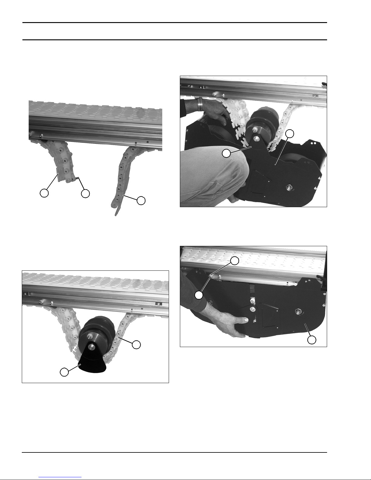
3. Raise weighted ta ke up box assembly, with plate
(Figure 25, item 1) on idler pulley assembly o n outside
of outer plate (Figure 25, item 2) weighted take up
assembly.
Figure 25
2
1
Figure 25
Figure 23
Weighted Take-Up
1. Instal l idler pulley ass em b ly (Figure 24, item 1) onto
belt (Figure 24,item 2).
Figure 24
2
1
Figure 24
4. Raise weighted ta ke up assembly (Figure 26, item 1)
with notch (Figure 26, item 2) in assembly mating with
stud (Figure 26, item 3) on conveyor frame.
Figure 26
3
2
1
Figure 26
2. Make sure teeth on pulley and guard are facing mating
teeth on take up box assembly.
Dorner Mfg. Corp. 16 851-757 Rev. A
2200 Series SmartFlex Conveyors
Page 17
Installation
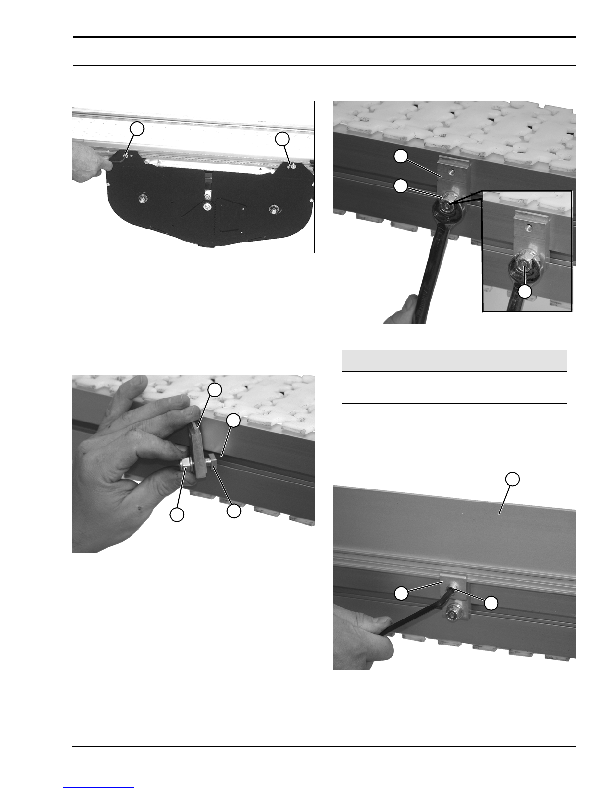
5. Install and tighten two hex head screws (Figure
27, item 1) on each sid e to secure assemb ly to fram e.
Figure 27
1
1
Figure 27
Install Guiding
All guiding must be located and installed by the end user.
Standard 1.5” Guiding
1. Install stud (Figure 28, item 1) onto retaining clip
(Figure 28, item 2) with nut (Figure 28, item 3).
Figure 28
2
3. Fasten retaining clip (Figure 29, item 1) to conveyor
with nut (Figure 29, item 2) on stud.
Figure 29
1
2
3
Figure 29
NOTE
Be certain that slot (Figure 29, item 3) is
close to vertical when finished tightening nut.
4
3
1
Figure 28
2. Install stud (Figure 28, item 1) into side rail channel
(Figure 28, item 4). The end clips should be no greater
than 12" from end of the conveyor.
4. Tighten nuts ( Figure 29, item 2).
5. Install guide (Fig ure 30, item 1) and retaining clip
(Figure 30, item 2) to con veyor side rail with socket
head screw (Figure 30, item 3).
Figure 30
1
2
3
Figure 30
851-757 Rev. A 17 Dorner Mfg. Corp.
2200 Series SmartFlex Conveyors
Page 18
Installation
Fully Adjustable Guiding
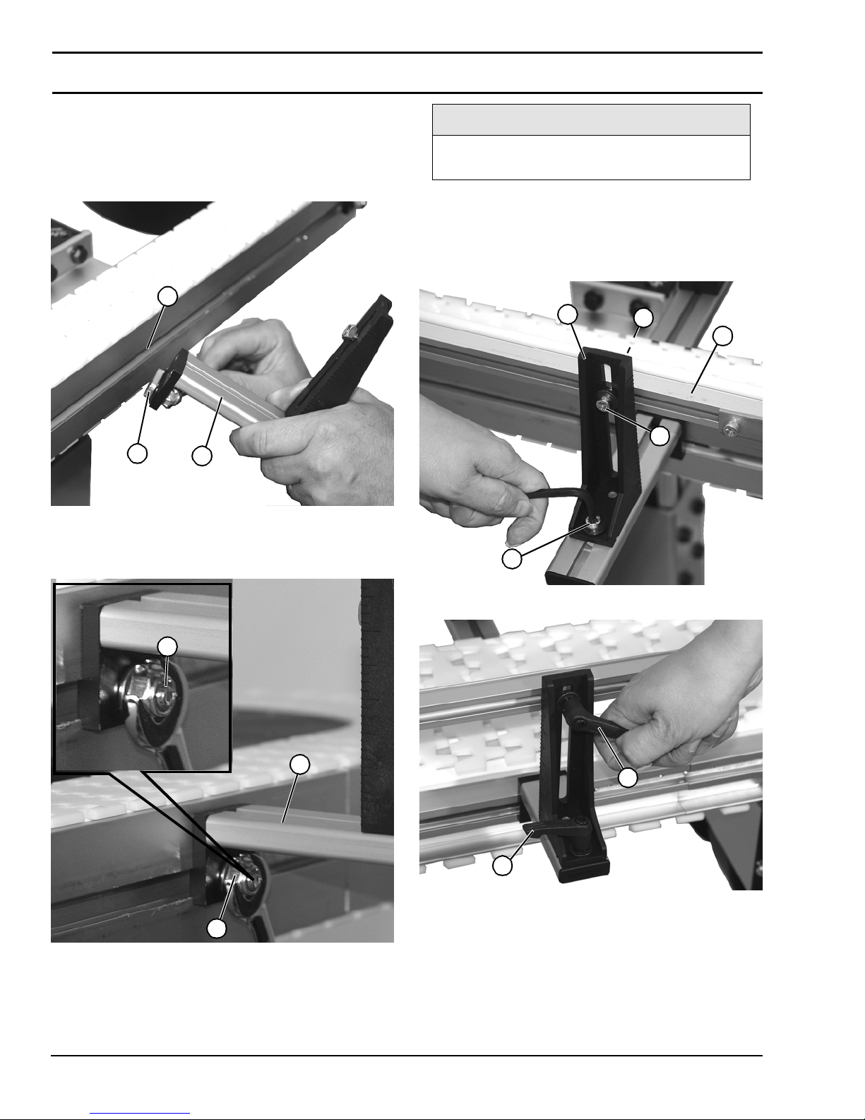
1. Install stud (Figure 31, item 1) on guiding assembly
(Figure 31, item 2) into side rail channel (Figure
31, item 3). The end guiding assembl ies should be no
greater than 12" f r o m end of the co nveyor.
Figure 31
3
1
2
NOTE
Be certain that slot (Figure 32, item 3) is
close to vertical when finished tightening nut.
3. Tighten nuts (F igure 32,item 2).
4. Install guide rail (Figure 33, item 1) onto squar e nut
(Figure 33, item 2) onto mounting bracket (Figure
33, item 3) with socket he ad screw (Figure 33, item 4)
or handle (Figur e 34, item 1) for tool-less guiding.
Figure 33
3
2
1
4
Figure 31
2. Tighte n stud on guidi ng assembly (Figur e 32, item 1) to
conveyor with nut (Figure 32, item 2) on stud.
Figure 32
3
1
2
Figure 32
5
Figure 33
Figure 34
1
2
Figure 34
5. Loosen socket head screw (Figure 33, item 5) or handle
(Figure 34, item 2) and adjust mounting bracket
(Figure 33, item 3) as needed.
Dorner Mfg. Corp. 18 851-757 Rev. A
2200 Series SmartFlex Conveyors
Page 19
Installation
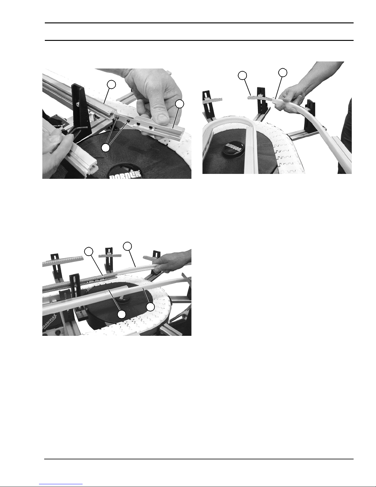
6. For curves, install inside of curve guide rail (Figure
35, item 1) to straight guide rails (Figure 35, item 2).
Tighten set screws (Figure 35,item 3).
Figure 35
2
1
3
Figure 35
7. To i nsta ll c urve ass embl y guiding, sta rt a t one en d of the
conveyor and slid e the guiding over the guide rails.
8. On the inside of the curve , inst all inn er guidin g (Figure
36, item 1) onto both of the inne r guide rails (Figure
36, item 2).
Figure 36
9. On outside of curve, install guidin g ( Figure 37, item 1)
on the guide supports (Figure 37, item 2).
Figure 37
2
1
Figure 37
10. To adjust guiding width loosen screws (Figure
33, item 5) or han d le (Figure 34 , i tem 2 ). Adjust to
desired width. Tighten screw or handle.
11. To adjust guiding height loosen screws (Figure
33, item 4) or han d le (Figure 34 , i tem 1 ). Adjust to
desired height. Tighten screw or handle.
2
Figure 36
1
1
2
851-757 Rev. A 19 Dorner Mfg. Corp.
2200 Series SmartFlex Conveyors
Page 20
Installation
Install Drive Package
NOTE
For detailed assembly instructions, refer to
the appropriate Drive Packages Installation,
Maintenance and Parts Manual.
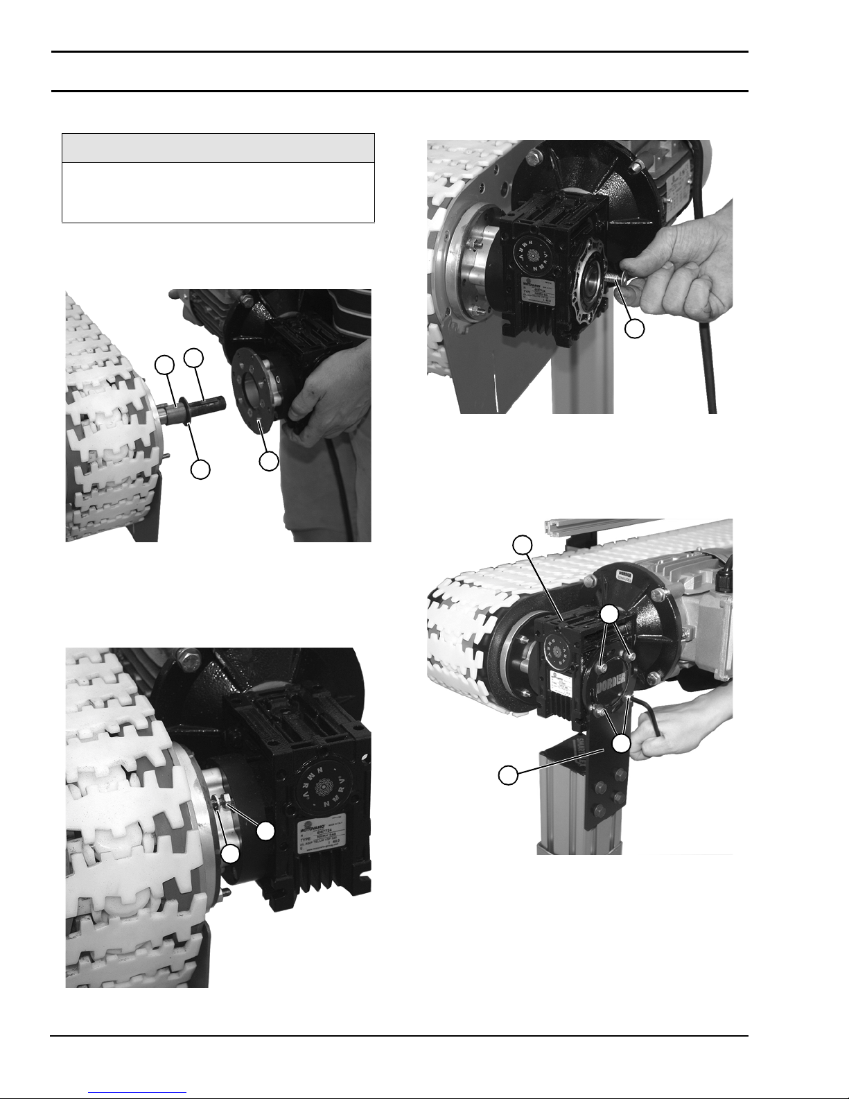
1. Install spacer (when applicable) (Figure 38, item 1),
washer (Figure 38, item 2), and key (Figure
38, item 3) onto drive shaft.
Figure 38
3
1
2
4
4. Install and tighten flat head screw (Figure 40, item 1)
onto the dr ive shaft.
Figure 40
1
Figure 40
5. Install drive motor stand mounting bracket (Figure
41, item 1) onto the drive motor (Figure 41, item 2)
with four washers and socket head screws (Figure
41, item 3).
Figure 41
Figure 38
2. Attach the mot or (Figure 38,item 4) onto the drive
shaft.
3. Install four washers ( Figure 39,item 1) and nuts
(Figure 39, item 2) to secure motor to conveyor.
Figure 39
2
1
2
3
3
1
Figure 41
Figure 39
Dorner Mfg. Corp. 20 851-757 Rev. A
2200 Series SmartFlex Conveyors
Page 21
Preventive Maintenance and Adjustment
A
A
A
Required Tools
• 3/32” hex wrench
• 3 mm hex wrench
• 4 mm hex wrench
• 5 mm hex wrench
• 6 mm hex wrench
• 8 mm hex wrench
• 10 mm wrench
• 13 mm wrench
• 16 mm wrench
• Belt Removal Tool #203480
Checklist
• Keep service parts on hand. Refer to the "Service Parts"
section start ing on page 40 for recommendations.
• Replace any worn or damaged parts .
Lubrication
No lubrication is required. Replace bea rings if worn.
Conveyor Belt Replacement
WARNING
SEVERE HAZARD!
LOCK OUT POWER before removing guards
or performing maintenance. Exposed moving
parts can cause serious injury.
Replacing a Section of Belt
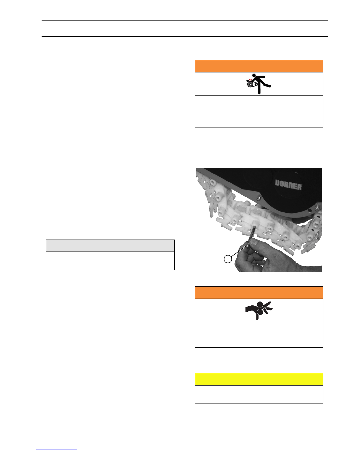
1. Use a punch and hammer or belt removal tool #203480
to push the belt rod (Figure 42, item 1) out by striking
the rod end.
Figure 42
Maintaining the Conveyor Belt
Troubleshooting
NOTE
Visit www.dorner.com for complete list of
troubleshooting solutions.
Inspect conveyor belt for:
• Surface cuts or wear
• Skipping
Damage to belt links or rods, surface cuts and / or
wear indic ate:
• Sharp or heavy parts impacting belt
• Jammed parts
• Accu mulated d ir t
• Foreign material inside the co nveyor
• Improperly positioned accessories
Skipping indicates:
• Excessive load on bel t
• Worn spindle or impact ed dirt on drive spindle
1
Figure 42
WARNING
SEVERE HAZARD!
If conveyor belt is damaged or worn, replace
belt section.
2. Remove the belt rods on both sides of the section of belt
being replaced.
3. Replace old section of belt.
CAUTION
851-757 Rev. A 21 Dorner Mfg. Corp.
DO NOT reuse belt rods that are damaged or
show signs of wear.
2200 Series SmartFlex Conveyors
Page 22
Preventive Maintenance and Adjustment
A
A
NOTE
Before inserting belt rod to connect belt ends,
be certain that the slack on belt is showing in
slotted area (Figure 43, item 1) on convey or
drive end.
Figure 43
1
Figure 43
Replacing the Entire Belt
1. Use a punch and hammer or belt removal tool #203480
to push the bel t r o d (Figure 44, item 1) out by striking
the rod end.
Figure 44
NOTE
Drive spindle shaft assembly replacement is
recommended with belt replacement (see
“Drive Spindle Shaft Assembly” on page 27).
CAUTION
DO NOT reuse belt rods that are damaged or
show signs of wear.
Conveyor Belt Tensioning
WARNING
SEVERE HAZARD!
LOCK OUT POWER before removing guards
or performing maintenance. Exposed moving
parts can cause serious injury.
NOTE
Belt should not be stretched during
installation. A proper length of belt can be
installed by interlocking the ends by hand
without excess links.
2
1
Figure 44
2. Slide the old belt (Figu re 44, item 2) off the convey or
frame.
3. Replace the old belt with a new one. Refer to “Belt
Installation” on page 14.
1. Remove one or more belt links to take up tension. Refer
to “Replacing a Section of Belt” on page 21.
NOTE
Before inserting belt rod to connect belt ends,
be certain that the slack on belt is showing in
slotted area (Figure 45, item 1) on convey or
drive end.
Figure 45
1
Figure 45
Dorner Mfg. Corp. 22 851-757 Rev. A
2200 Series SmartFlex Conveyors
Page 23
Preventive Maintenance and Adjustment
Wear Strip Removal
Replace the wear strips if they become worn.
NOTE
Top and bottom wear strips are shipped
pinned/attached at various places on
conveyor.
1. Remove belt. S ee “Conveyor Belt Replacement” on
page 21.
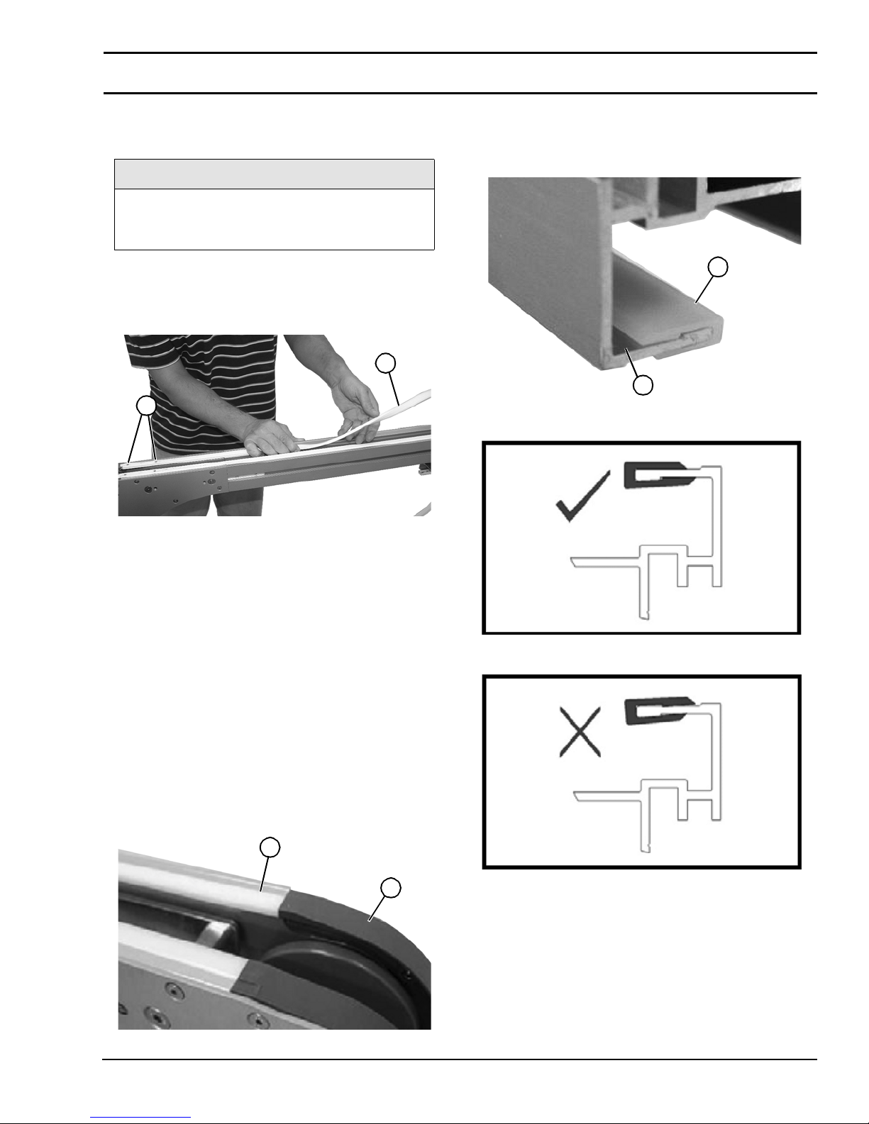
2. Remove wear strip (Figure 46, item 1) from top of
frame assembly up to pinned end (Figure 46, item 2).
Figure 46
1
2
2. Make sure the wear strip (Figure 48, item 1) is properly
mounted and snaps onto the fr ame (Figure 48, item 2).
Please identify the longer flange of the wear strip must
always face the inside of the conveyor.
Figure 48
1
2
Figure 48
Figure 46
3. Cut and remove worn wear strip sec tion and replace
with new wear strip. See “Wear Strip Installation” on
page 23.
4. Remove lower wear strips, as needed, repeat procedure
used for upper wear strips.
Wear Strip Installation
1. Remove wear strips. See “Wear S trip Removal” on
page 23.
Attaching Wear Strip on Straight Frame
1. Start the wear strips (Fig u re 4 7 , item 1 ) at an id l er en d
(Figure 47, item 2) of conveyor. Separate the top and
bottom flange of the wear strip at the end of rail and
press into place.
Figure 47
1
2
Correct Installation
Wrong Installation
Figure 47
851-757 Rev. A 23 Dorner Mfg. Corp.
2200 Series SmartFlex Conveyors
Page 24
Preventive Maintenance and Adjustment
Attaching Wear Strip on Conveyor Frame
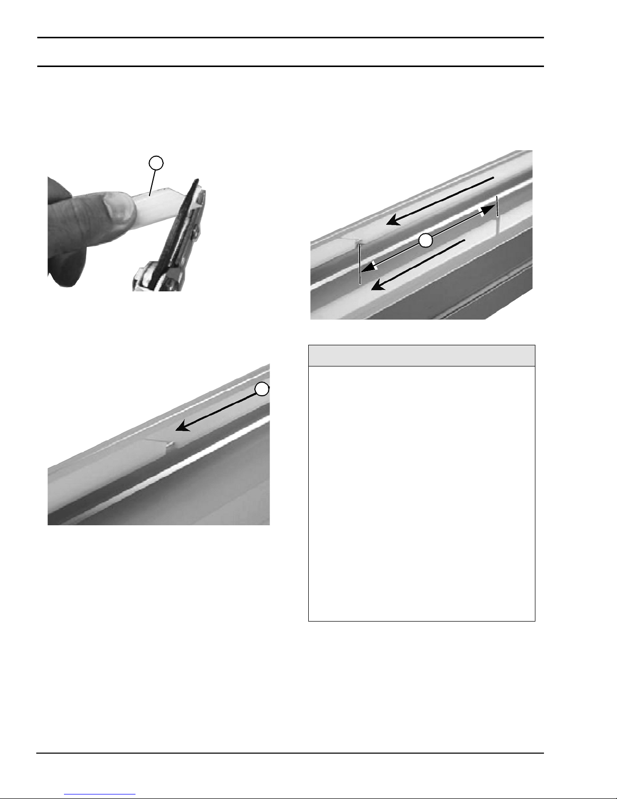
1. Cut both wear stri p (Figure 49, item 1) ends in a 45°
angle. The begin ning of a ne w wear strip (in the
direction of travel) must cut back a small angle.
Figure 49
1
Figure 49
2. Allow a space of approxi ma tely 1/16” to 1/8” (Figure
50, item 1) between two wear strip ends. The travel
direction is indicated by arrow.
Figure 50
3. Do not place two wear strip joints opposite each other.
Make sure there is a di stance of at least 4” (Figure
51, item 1) between them to make the chain run
smoother . This does not apply to a wear stri p tha t begin s
by an idler unit or af ter a drive tail, where joints are
always parallel.
Figure 51
1
Figure 51
NOTE
Figure 50
Try to let the wear strip run in as continuous
1
lengths as possible by reducing number of
breaks, except in circumstances stated
below:
• It is recommended to use short wear strips
(75” - 100”) where chemicals may have an
effect on the wear strip composition.
• It is important to cut the wear strip and allow
for elongation in high load areas. Cutting is
required in wheel bends (see following page),
at idler tails and where the conveyor will be
heavily loaded, especially at drive unit. This
prevents the wear strip from stretching out
and entering into the drive tail, which may
block the chain movement.
• Never join wear strip in horizontal or vertical
bends, since forces are higher on the wear
strip side in these sections. Instead, place the
joint before the bend.
• Avoid joining wear strips on top of the
conveyor frame joints.
Dorner Mfg. Corp. 24 851-757 Rev. A
2200 Series SmartFlex Conveyors
Page 25
Preventive Maintenance and Adjustment
Attaching Wear Strip at Wheel Bend
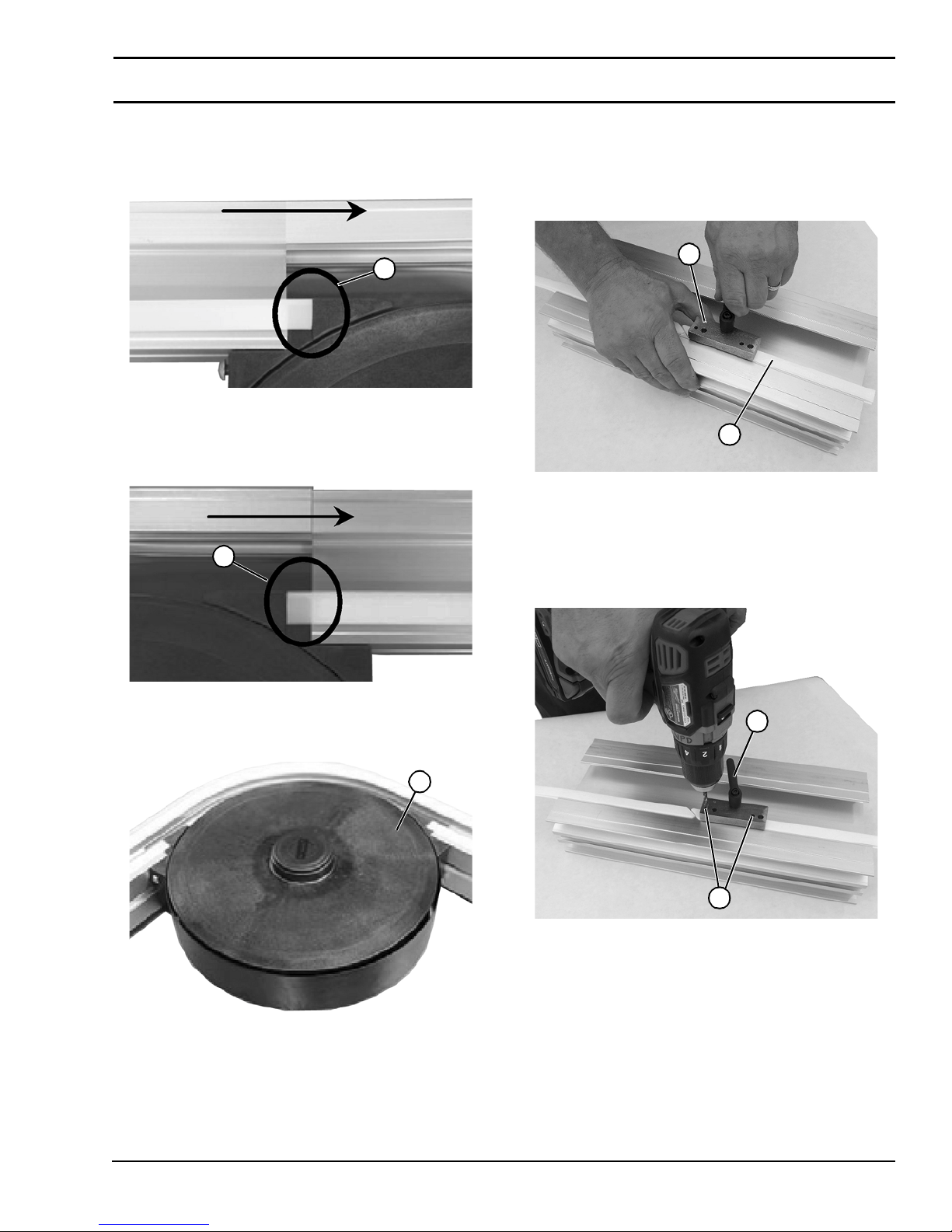
1. Cut the wear strip end fl at (Figure 52, item 1). Make
sure there is no gap cr ea ted at the plastic mol ding part.
Figure 52
1
Figure 52
2. The step is applied onto out feed end (Figure
53, item 1) as well.
Figure 53
1
Attaching Wear Strip
1. Attach wear strip replacement tool (Figure 55, item 1)
over wear strip (Figure 55, item 2) and frame near the
beginning of each wear strip section. Ti ghtly secure in
place.
Figure 55
1
2
Figure 55
2. Using the wear strip replacem ent tool (Figure
56, item 1) drill two h oles through the two small
location holes (Figure 56, item 2) through the wear
strip and frame using the #18 drill bit from the wear
strip replacement kit.
Figure 56
Figure 53
3. In the outer bend (Figur e 54, item 1), make sur e that the
wear strip is proper ly connected to the conveyor fra me.
Figure 54
1
Figure 54
1
2
Figure 56
3. Remove debris from conveyor frame.
4. Relocate wear strip replacement tool to align the two
larger guide holes with the holes drilled in the frame.
851-757 Rev. A 25 Dorner Mfg. Corp.
2200 Series SmartFlex Conveyors
Page 26
Preventive Maintenance and Adjustment
A
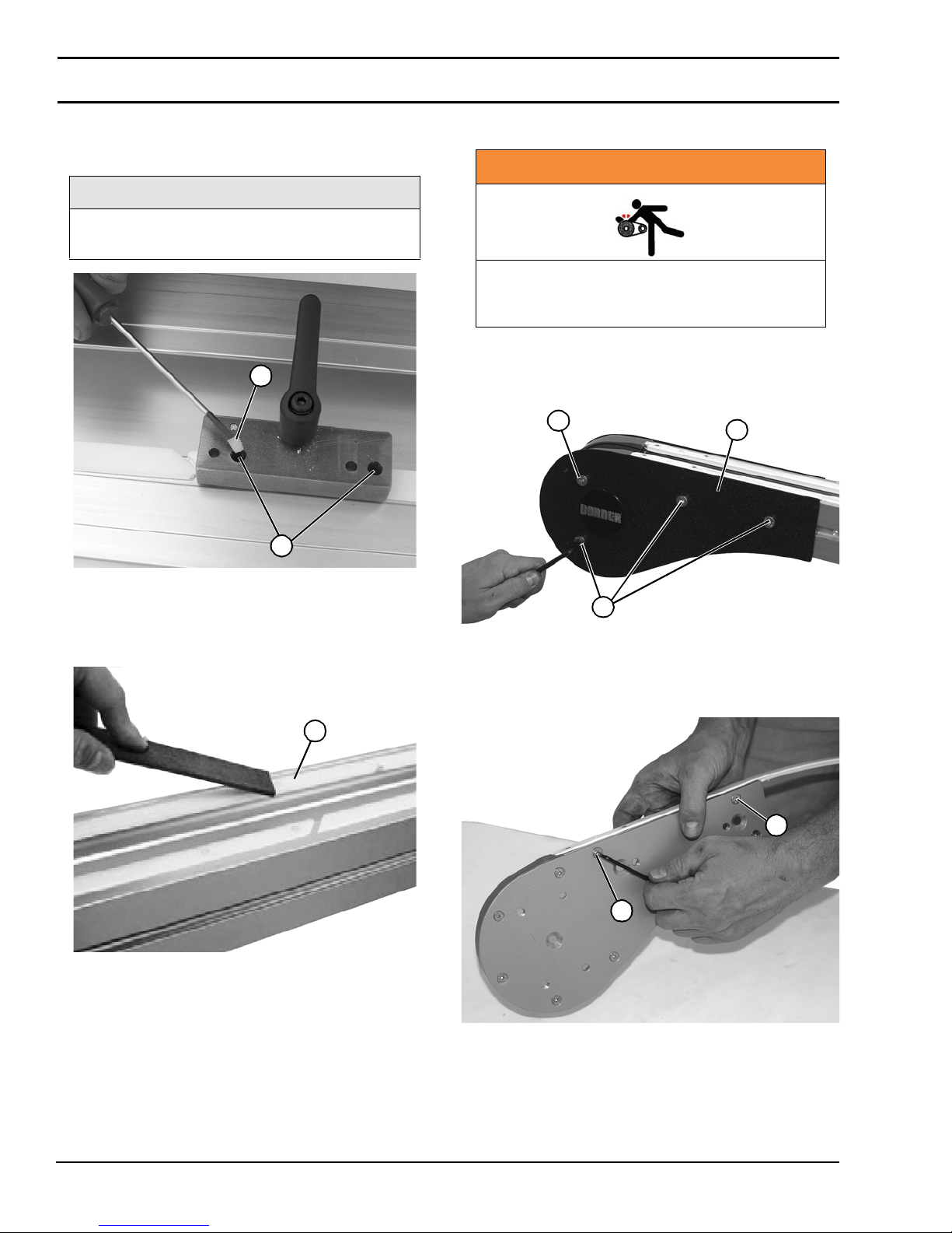
5. Pressing down firmly, ins tall nylon set screws (Figure
57, item 1) through larger guide holes (Figure
57, item 2) into conveyor frame.
NOTE
Nylon set screw should be almost flush with
the wear strip top when installed correctly.
Figure 57
1
2
Idler Pulley Assembly
WARNING
Exposed moving parts can cause severe
injury. LOCK OUT POWER before removing
guards or performing maintenance.
1. Remove four (4) head plate faste ning screws (Figure
59, item 1) and remove cover plate (Fi gure 59,item 2).
Repeat on opposite side of idler tail assembly.
Figure 59
1
2
Figure 57
6. Using a file, scrape off the top of the nylon set screw
above the wear strip (Figure 58, item 1) to assur e a
smooth surface for the belt.
Figure 58
1
Figure 58
1
Figure 59
2. Remove two flat head screws (Figure 60, item 1) from
idler head plate ass embly.
Figure 60
1
1
Dorner Mfg. Corp. 26 851-757 Rev. A
Figure 60
2200 Series SmartFlex Conveyors
Page 27
Preventive Maintenance and Adjustment
A
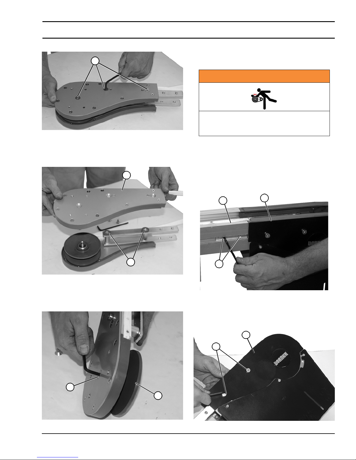
3. Remove three flat head screws (Figure 61, item 1).
Figure 61
1
Figure 61
4. Remove the head plate (Figure 62, item 1) from the
idler end, making note of two spacers (Figure
62, item 2) on idler head plate ass embly.
Figure 62
1
6. Install components reverse of removal.
Drive Spindle Shaft Assembly
WARNING
Exposed moving parts can cause severe
injury. LOCK OUT POWER before removing
guards or performing maintenance.
1. Remove the gearmotor. For detailed instructions, refer
to the appropriate drive package manual.
2. Loosen two socket head set screws (Figu re 64, item 1)
on each side of conveyor, and remove the drive ta il
assembly (Figure 64, item 2) from the conveyor frame
(Figure 64, item 3 ).
Figure 64
3
2
2
Figure 62
5. Remove flat head screw (Figure 63,item 1) and
remove idler pulley (Figur e 63, item 2) from idler head
plate assembly.
Figure 63
1
2
Figure 63
1
Figure 64
3. Remove two (2) head plate cover fastening screws
(Figure 65, item 1 ) and remove cover plate (Figure
65, item 2).
Figure 65
2
1
Figure 65
851-757 Rev. A 27 Dorner Mfg. Corp.
2200 Series SmartFlex Conveyors
Page 28
Preventive Maintenance and Adjustment
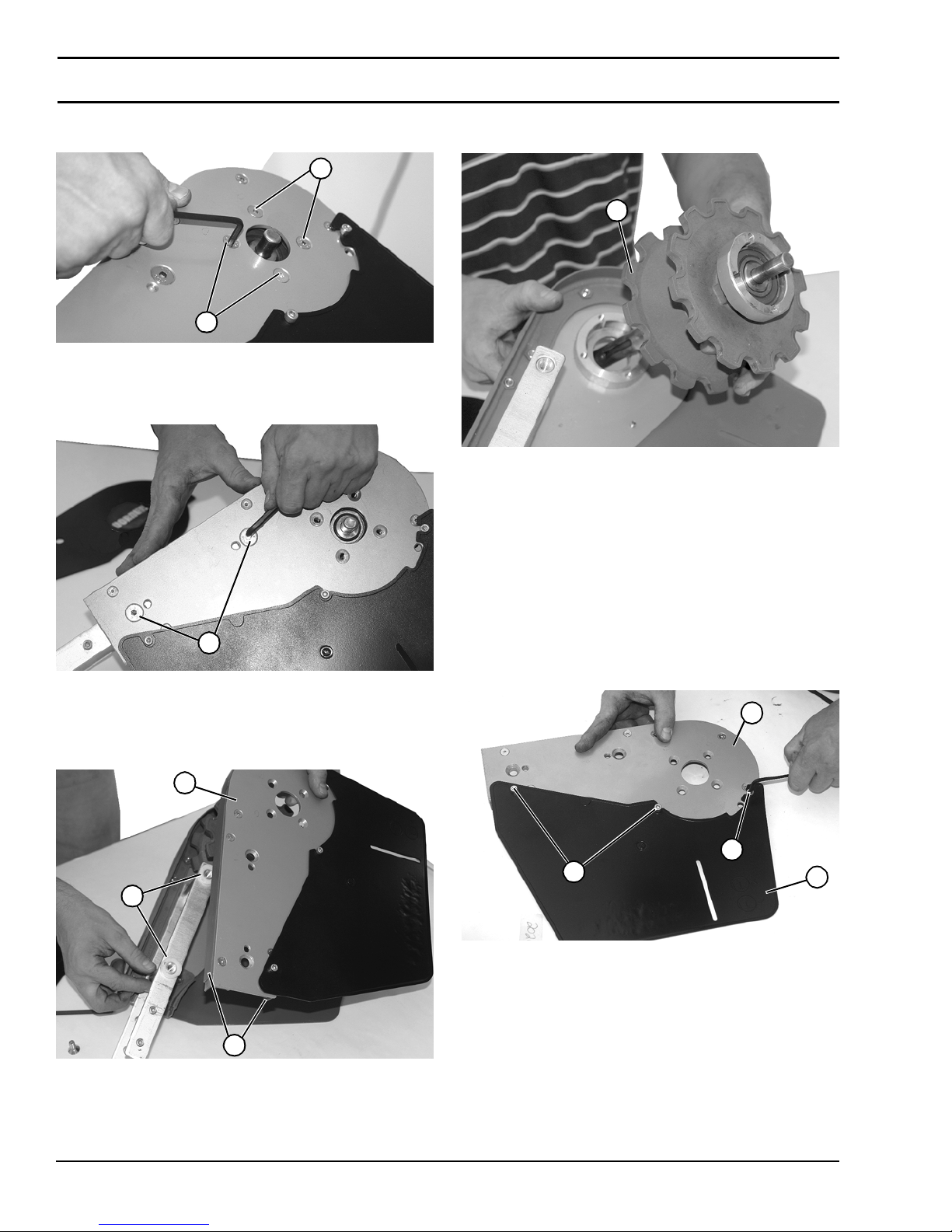
4. Remove four (4) socket head screws (Figure
66, item 1) on side of drive spindle.
Figure 66
1
1
Figure 66
5. Remove two (2) socke t head sc rews (Figure 67, item 1)
on side of drive spindle.
Figure 67
8. Remove spindle shaft assembly (Figure 69, item 1)
from idler head plate assembly.
Figure 69
1
Figure 69
9. Install components reverse of removal.
Retaining Guide Replacement
1
Figure 67
6. Remove the head plate (Figure 68, item 1) from the
drive end, making note of two spacers (Figure
68, item 2) on idler head plate ass embly.
Figure 68
1
2
Drive End
1. Remove drive spindle shaft assembly. See “Drive
Spindle Shaft Asse mb ly” on page 27.
2. Remove three socket head screws (Figure 70, item 1)
and remove drive plate guard (Fig ure 70, item 2) from
drive plate (Figure 70, item 3).
Figure 70
3
1
1
Figure 70
2
3
Figure 68
7. To remove upper and lower retaining guides (Figure
68, item 3), see “Retaining Guide Replacement” on
page 28.
Dorner Mfg. Corp. 28 851-757 Rev. A
2200 Series SmartFlex Conveyors
Page 29
Preventive Maintenance and Adjustment
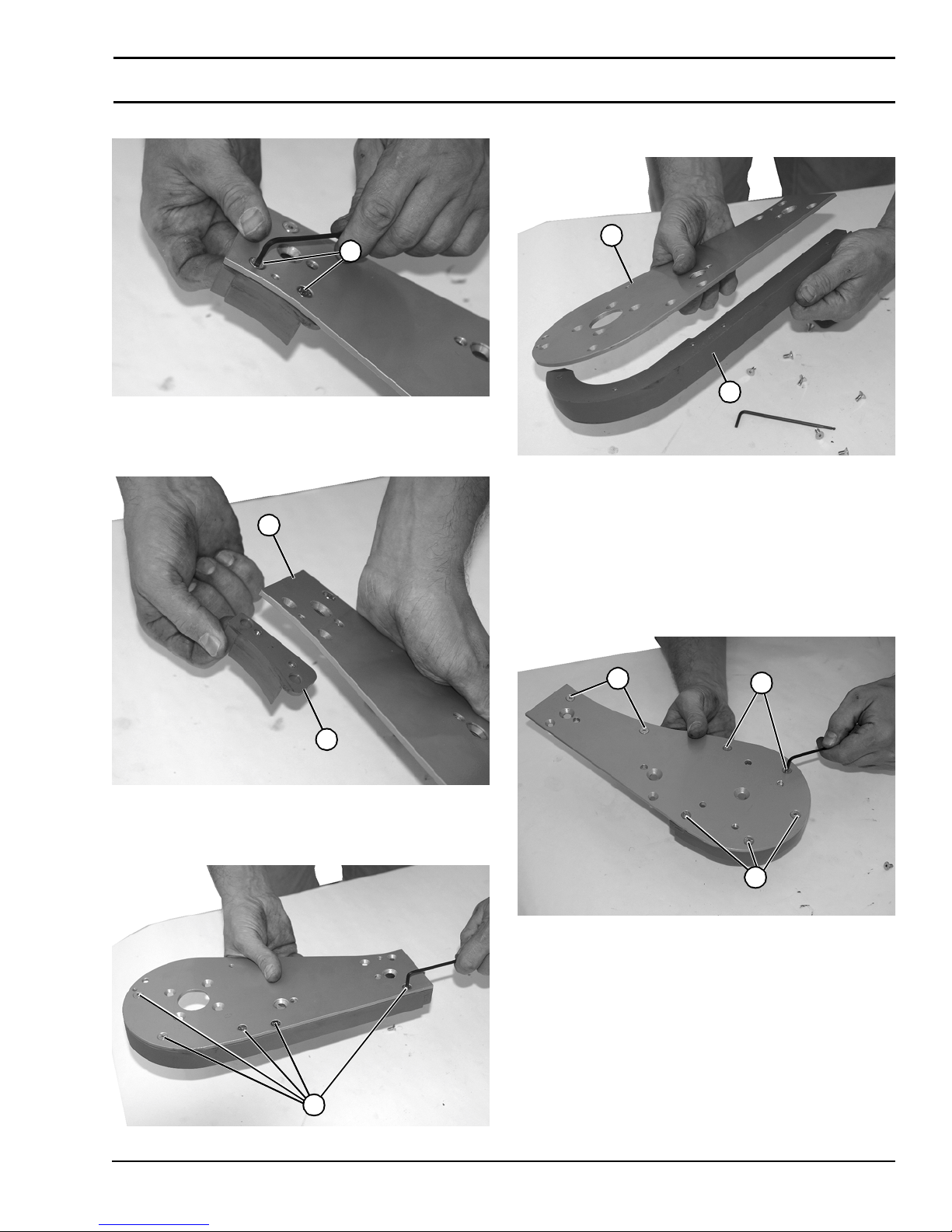
3. Remove two socket head screws (Figure 71,item 1).
Figure 71
1
Figure 71
4. Remove lower reta ining guid e (Figure 72, item 1) from
drive plate (Figure 72, item 2).
Figure 72
2
6. Remove upper retain ing guide (F ig ur e 74,item 1) from
drive plate (Figure 74, item 2).
Figure 74
2
1
Figure 74
7. Install components reverse of removal.
Idler End
1. Remove idler pulley assembly. See “Idler Pulley
Assembly” on page 26.
2. Remove seven (7) socket head screws (Figure
75, item 1) from idler head plate assembly.
Figure 75
1
Figure 72
5. Remove five (5) socket head screws (Figure
73, item 1).
Figure 73
1
1
1
1
Figure 75
Figure 73
851-757 Rev. A 29 Dorner Mfg. Corp.
2200 Series SmartFlex Conveyors
Page 30
Preventive Maintenance and Adjustment
A
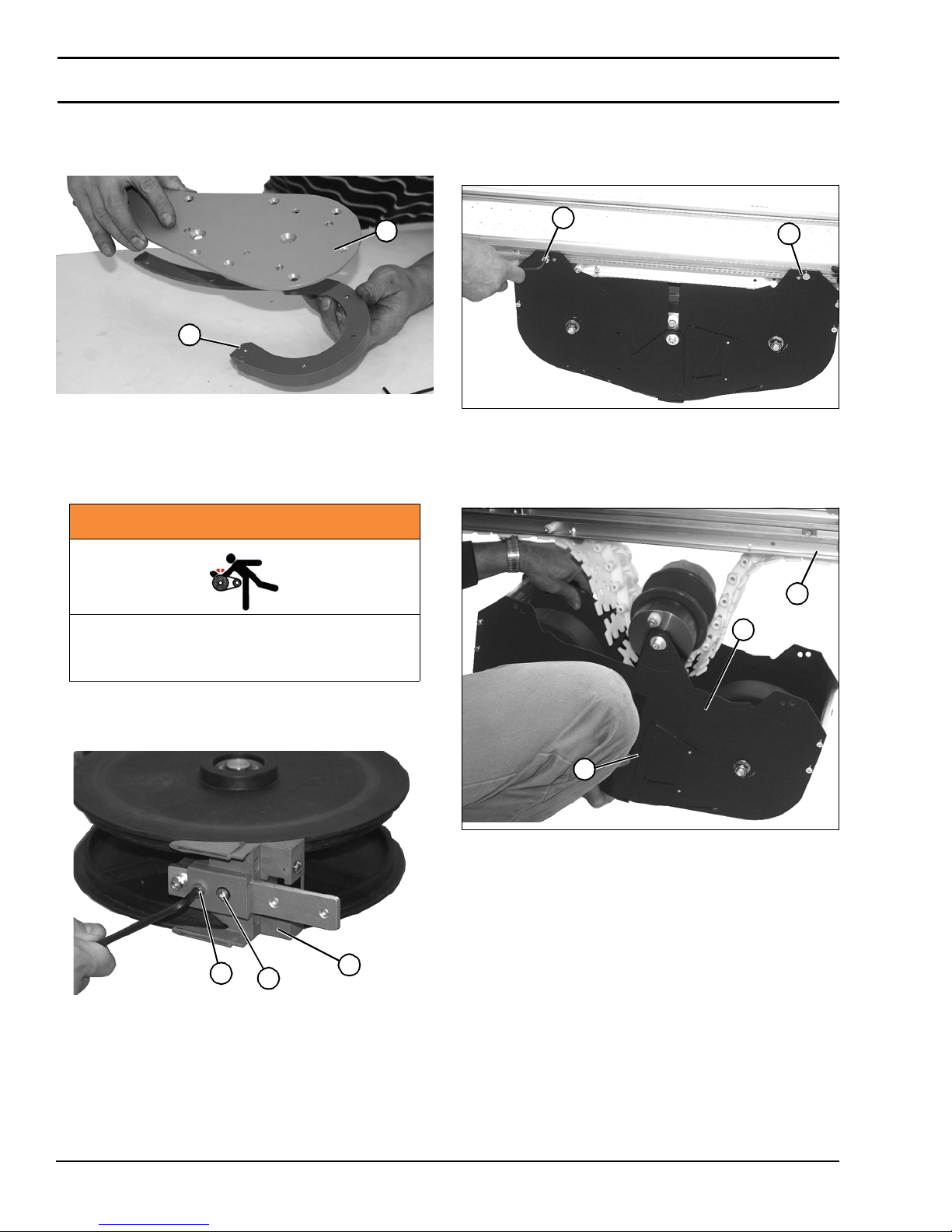
3. Remove retaining guide (Figu re 7 6 , item 1 ) fr o m i d ler
head plate assembly (Figure 76, item 2). Replace
components, as needed.
Figure 76
2
1
Figure 76
4. Install component s re verse of removal.
Curve Assembly
WARNING
Weighted Take-Up
1. Remove two socket head screws (Figure 78, item 1) on
each side securin g assembl y to frame.
Figure 78
1
1
Figure 78
2. Lower weighted take up assem bly (Figure 79, item 1)
from conveyor (Figure 79, item 2) by disengaging
locking teeth (Figure 79, item 3) on both sides.
Figure 79
Exposed moving parts can cause severe
injury. LOCK OUT POWER before removing
guards or performing maintenance.
1. Remove socket head screw (Figu re 7 7 , item 1 ) and
socket he ad scr e w (Figure 77, item 2) from corner
wheel assembly pi nch bracket (Figure 77,item 3).
Figure 77
1
2
3
Figure 77
2. Install component s re verse of removal.
2
1
3
Figure 79
Dorner Mfg. Corp. 30 851-757 Rev. A
2200 Series SmartFlex Conveyors
Page 31
Preventive Maintenance and Adjustment
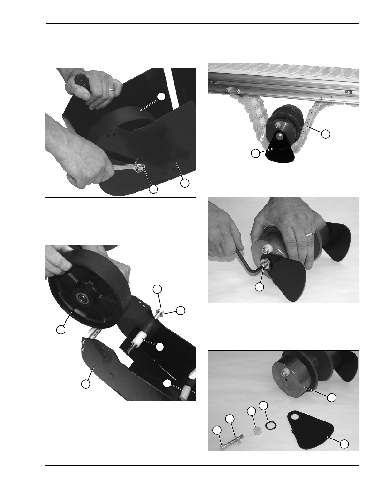
3. Use two wrenches to remove nut (Figure 80,item 1) on
bolt securi ng wheel (Fig u re 8 0 , item 2 ) onto weighted
take up assembly housing (Figure 80, item 3).
Figure 80
2
3
1
Figure 80
4. Remove bolt (Figure 81, item 1), washe r (Figure
81, item 2), two spacers (Figure 81, item 3), and wheel
(Figure 81, item 4) from take up assembly housing
(Figure 81, item 5).
Figure 81
5. Remove idler pulle y assem bly ( Fig ur e 8 2, item 1) from
belt (Figure 82, item 2).
Figure 82
2
1
Figure 82
6. Remove socket head screw (Figure 83, item 1) from
end of idler pulley assembly.
Figure 83
1
2
1
Figure 83
7. Remove bolt (Figure 84, item 1), washer (Figure
4
3
5
3
Figure 81
84, item 2), spacer (Figure 84, item 3), wave washer
(Figure 84, item 4), and plate (Figure 84,item 5) from
end of idler assembly (Figure 84, item 6).
Figure 84
6
4
3
2
1
5
Figure 84
851-757 Rev. A 31 Dorner Mfg. Corp.
2200 Series SmartFlex Conveyors
Page 32
Preventive Maintenance and Adjustment
8. Repeat on opposite side.
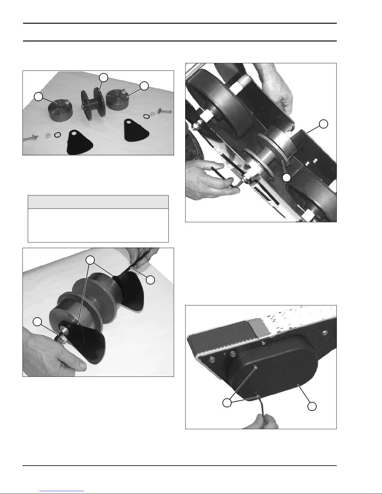
9. Remove two weights (Figure 85, item 1) from ea ch
side of pulley (Figure 85, item 2).
Figure 85
2
1
1
Figure 85
10. Install components reverse of removal, using two hex
wrenches (Figure 86, item 1) on each s ide o f idl er
assembly to tighten components.
NOTE
Be certain that notches (Figure 86, item 2)
on both plates are on top side, and spacers
are in same orientation, as shown, before
tightening components.
Figure 86
2
11. Instal l id ler pulley a ss embly (Figure 87, item 1) onto
weighted take up assembly (Figure 87, item 2).
Figure 87
2
1
Figure 87
12. Install remaining components reverse of removal.
Power Transfer
Removal
1
1
Figure 86
1. Remove two hex head screws (Figure 88, item 1) and
cover (Figure 88, item 2) from power transfer
assembly.
Figure 88
1
2
Figure 88
Dorner Mfg. Corp. 32 851-757 Rev. A
2200 Series SmartFlex Conveyors
Page 33
Preventive Maintenance and Adjustment
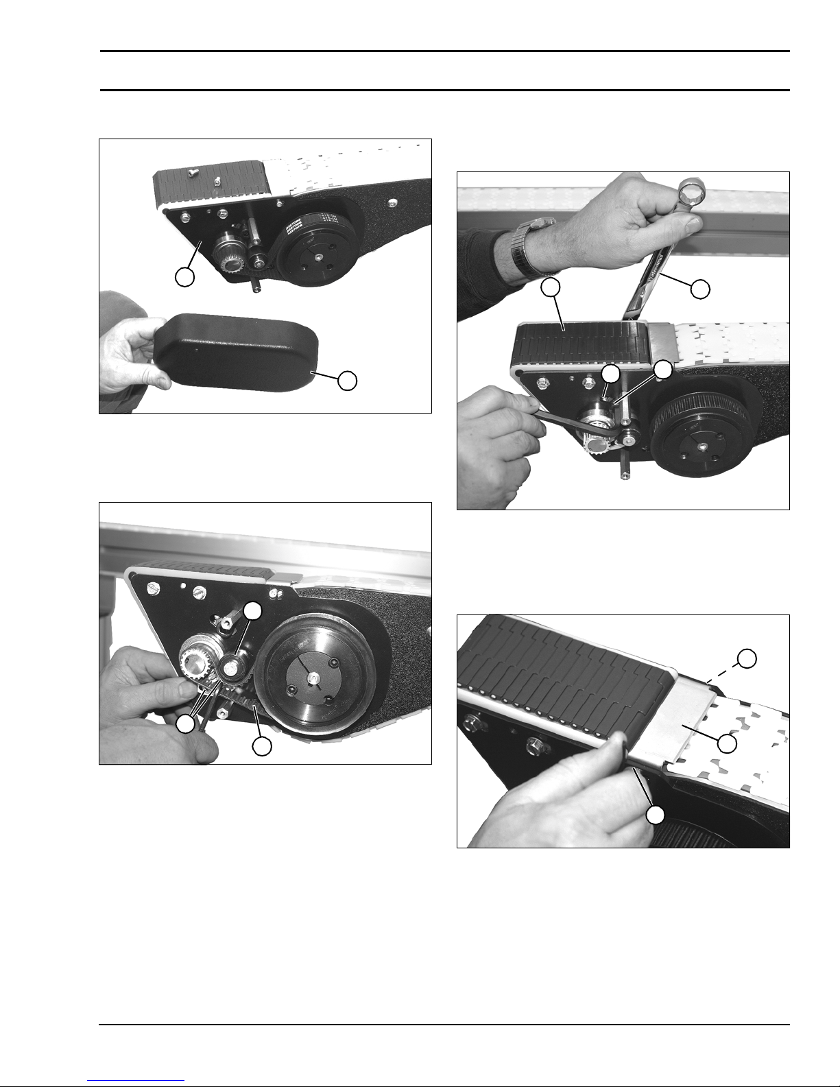
2. Remove power transf er cover (Figure 89, item 1) from
power transfer assembly (F igure 89, item 2).
Figure 89
2
1
Figure 89
3. Loosen two socket head screws (Figure 90, item 1)
holding tensioning pulley (Figur e 90, item 2) onto
timing belt (Figure 90, item 3).
Figure 90
5. While holding onto nut with a wrench (Figure
91, item 1) loosen socket head screw (Figure
91, item 2) to loosen tension on belt (Figure
91, item 3).
Figure 91
3
4
1
2
2
1
3
Figure 90
4. Remove timing belt (Figure 90, item 3) from assembly.
Figure 91
6. Slide assembly within slot (Figure 91, item 4) to
remove tension on belt.
7. Remove two socket head screws (Figure 92, item 1)
and tensioner plate (Figure 92, item 2).
Figure 92
1
2
1
Figure 92
851-757 Rev. A 33 Dorner Mfg. Corp.
2200 Series SmartFlex Conveyors
Page 34
Preventive Maintenance and Adjustment
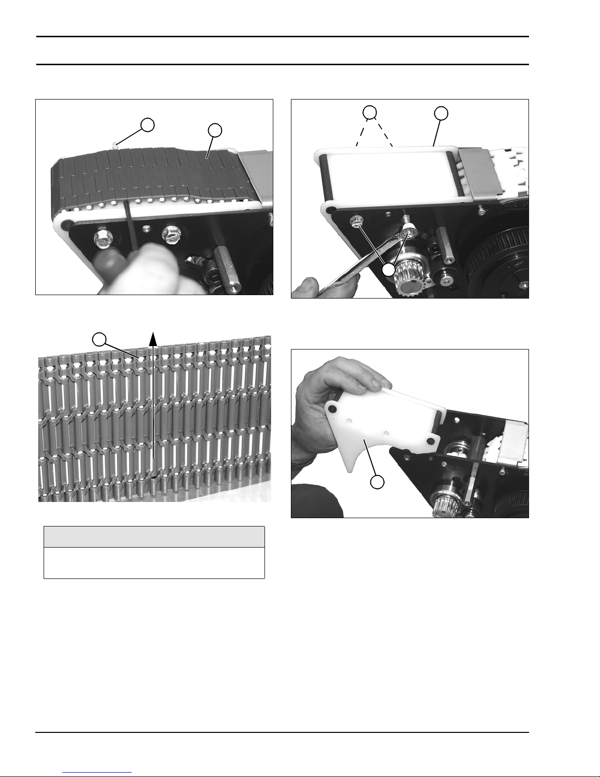
8. Lift slightly on belt (Figure 93,item 1) and push pin
(Figure 93, item 2) o u t of belt.
Figure 93
2
1
Figure 93
Figure 94
1
10. Remove four bol ts ( Figur e 95, item 1) holding wear bar
assembly (Figure 95, item 2) onto power transfer.
Figure 95
1
1
2
Figure 95
11. Remove wear bar assembly (Figure 96, item 1) from
power transfer.
Figure 96
Figure 94
NOTE
Note that head of pin (Figure 94, item 1)
should be removed in direction shown.
9. Remove belt.
Dorner Mfg. Corp. 34 851-757 Rev. A
1
Figure 96
2200 Series SmartFlex Conveyors
Page 35
Preventive Maintenance and Adjustment
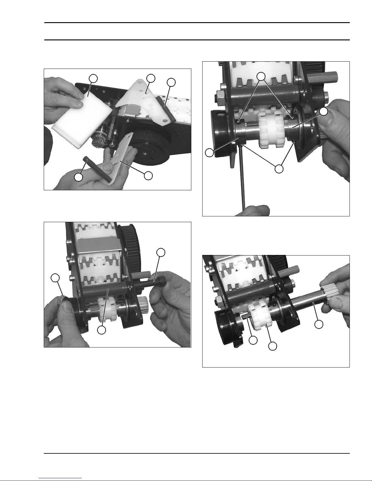
12. Disassemble side guide pla tes (Fi gure 97, item 1), wear
rods (Figure 97, item 2), and wear bar (Figure
97, item 3). Replace worn components.
Figure 97
3
2
1
2
1
Figure 97
13. Remove nut (Fig ure 98, item 1), bolt (Figure
98, item 2), and wear tube (Figure 98, item 3).
Figure 98
15. Loosen four set screws (Figure 99, item 1) on tw o
bearings (Figure 99, item 2).
Figure 99
1
2
2
1
Figure 99
2
1
3
Figure 98
14. Replace wear tube and install bolt and nut to secure.
16. Remove drive shaft (Figure 100, item 1), making
certain not to loose key (Figure 100, item 2) when
removing gear (Figure 100, item 3).
Figure 100
1
2
3
Figure 100
851-757 Rev. A 35 Dorner Mfg. Corp.
2200 Series SmartFlex Conveyors
Page 36
Preventive Maintenance and Adjustment
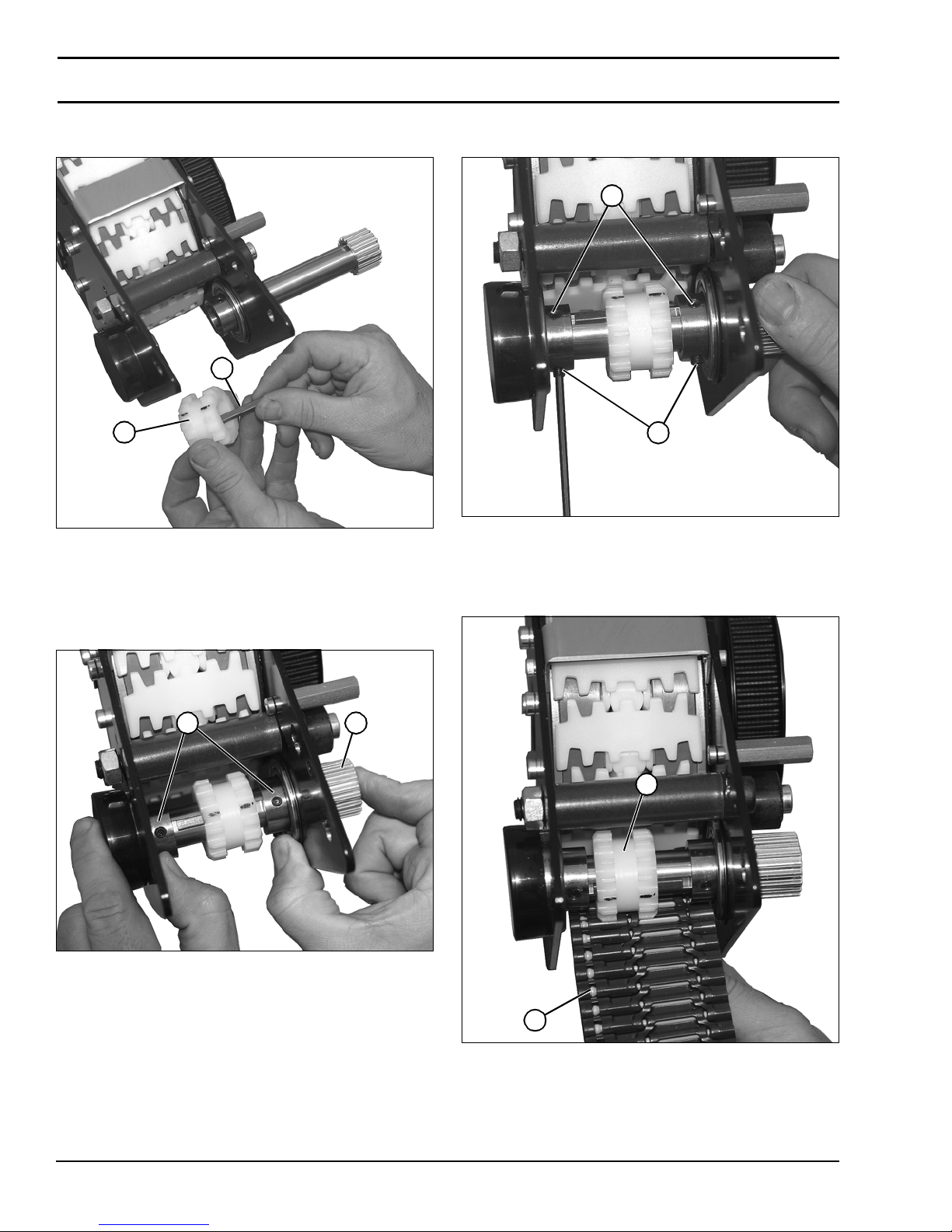
17. Remove key (Figur e 101,item 1) from gear (Figure
101, item 2).
Figure 101
1
2
Figure 101
Installation
1. Inst all drive shaft (Figure 102, item 1) on tw o beari n gs
(Figure 102, item 2) and press outward as shown.
Figure 102
2. Secure drive shaft onto bearings with four set scre ws
(Figure 103, item 1).
Figure 103
1
1
Figure 103
3. Raise belt (Figure 104, item 1) into position, and move
gear (Figur e 104, item 2) so that co gs line up with be lt,
as shown.
Figure 104
Figure 102
12
2
1
Figure 104
Dorner Mfg. Corp. 36 851-757 Rev. A
2200 Series SmartFlex Conveyors
Page 37
Preventive Maintenance and Adjustment
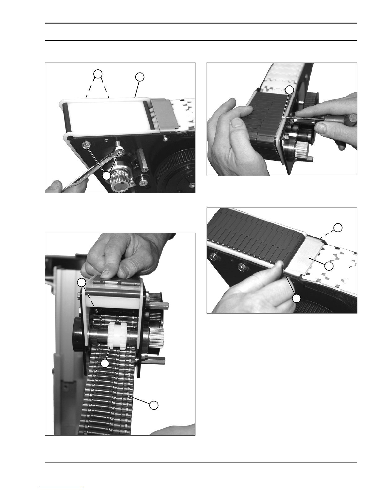
4. Install wear bar assembly (Figure 105, item 1) with
four bolts (Figure 105, item 2).
Figure 105
2
1
2
Figure 105
5. Guide belt (Figure 106, item 1) through wear bar
assembly with belt routing under gear (Figure
106, item 2) and over wear tube (Fig u re 106, item 3).
Figure 106
6. Bring ends of belt together and install pin (Figure
107, item 1).
Figure 107
1
Figure 107
7. Install tensioner plate (Figure 108, item 1) with two
socket h ead scre ws (Figure 108,item 2).
Figure 108
2
1
3
2
Figure 108
2
1
Figure 106
851-757 Rev. A 37 Dorner Mfg. Corp.
2200 Series SmartFlex Conveyors
Page 38
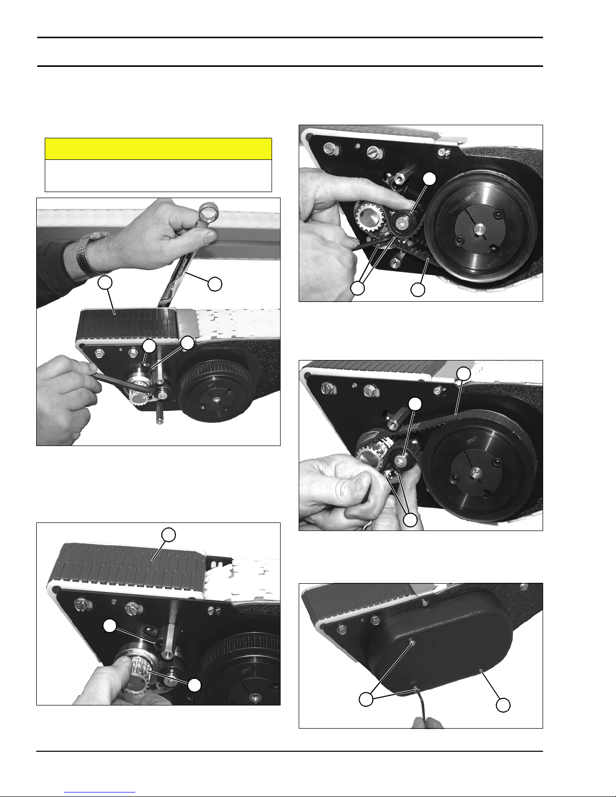
Preventive Maintenance and Adjustment
A
8. While holding onto nut with a wrench (Figure
109, item 1), slide assembly within slot (Figure
109, item 2) to remove excess slack from belt (Figure
109, item 3). Tighten hex head screw (Figure
109, item 4).
CAUTION
DO NOT overtighten belt or excessive wear
will occur.
Figure 109
3
2
1
4
10. Install timing belt:
• On idler end, route and install belt (Figure 111, item 1)
as shown. Press down on tensioner (Figur e 111, item 2)
and tighten two hex head screws (Figure 1 11, item 3).
Figure 111
2
3
1
Figure 111
• On drive end, route and install belt (Figure 112, item 1) as
shown. Press upward on tens ioner (Figure 112, item 2)
and tighten two hex head screws (Figure 112, item 3)
Figure 112
Figure 109
9. Rotate drive shaft (Figure 110, item 1) to verify
tightness of belt (Figure 110, item 2). Belt should turn
freely. Loosen hex head screw (Figure 110, item 3) and
adjust , if necessary.
Figure 110
2
3
1
2
3
Figure 112
11. Install cover (Figure 113 ,item 1) with two hex head
screws (Figure 113, item 2).
Figure 113
1
Figure 110
Dorner Mfg. Corp. 38 851-757 Rev. A
2200 Series SmartFlex Conveyors
2
1
Figure 113
Page 39
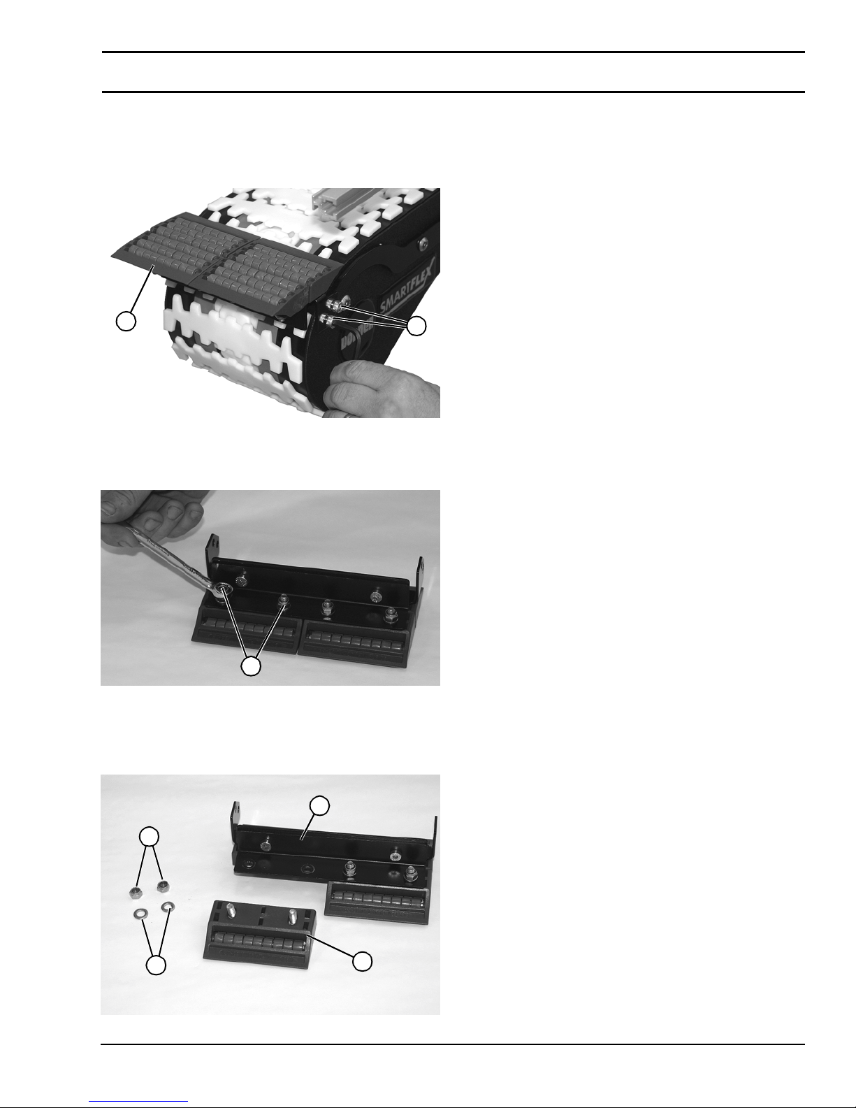
Preventive Maintenance and Adjustment
Roller Transfer
1. Remove two hex head scre ws (Figure 114, item 1) on
each side of conveyor, and remove roller tran sfer
assembly (Figure 114, item 2) from conveyor.
Figure 114
2
1
Figure 114
2. Remove two nuts (Figure 115, item 1) from one end of
roller tr ansfer ass embly.
Figure 115
1
Figure 115
3. Remove nuts (Figure 116,item 1), was he rs (F igure
116, item 2), and roller transfer (Figure 116, ite m 3)
from frame (Figur e 116 ,item 4).
Figure 116
1
2
Figure 116
851-757 Rev. A 39 Dorner Mfg. Corp.
4
3
2200 Series SmartFlex Conveyors
Page 40
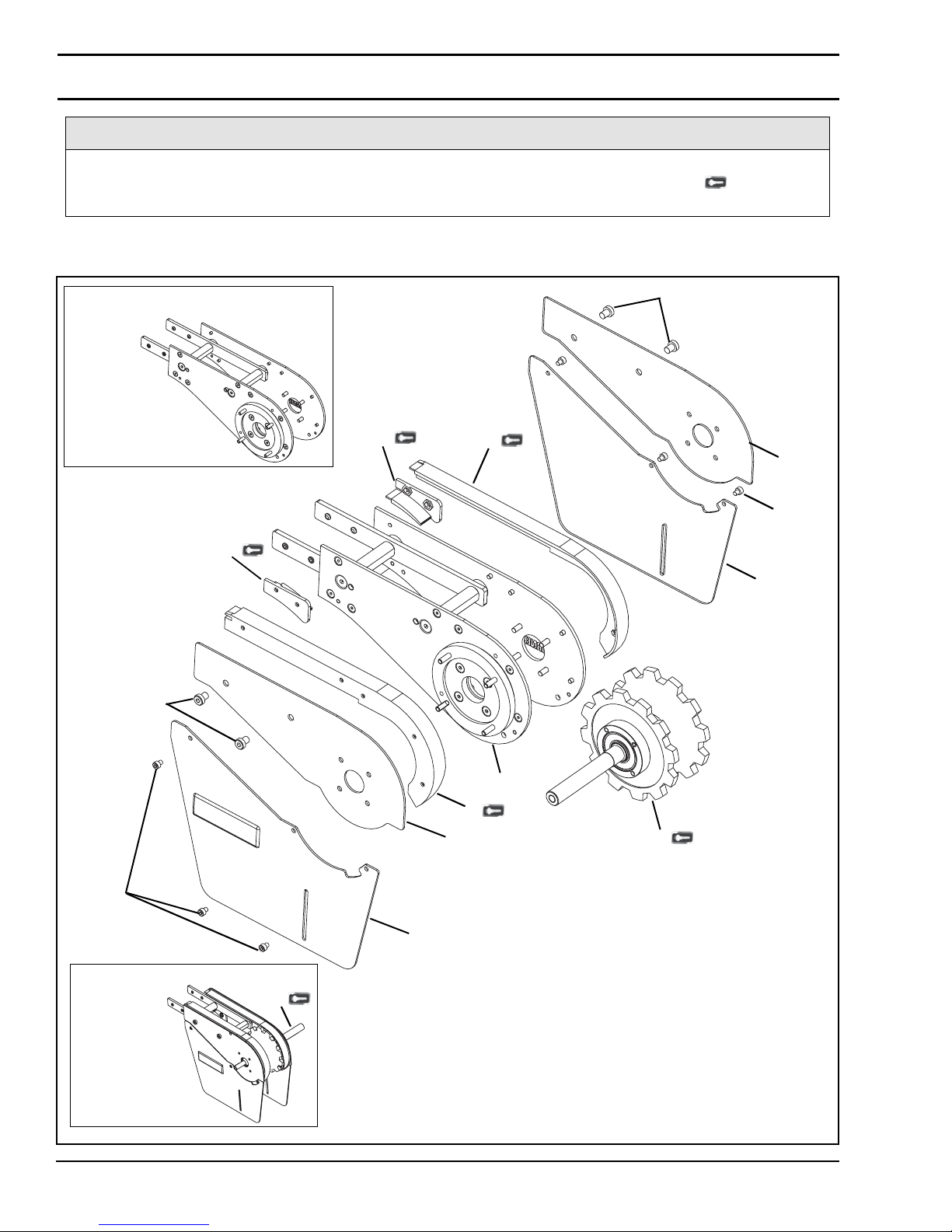
Service Parts
NOTE
For replacement parts other than those shown in this section, contact an authorized Dorner Service Center
or the factory. Key Service Parts and Kits are identified by the Performance Parts Kits logo . Dorner
recommends keeping these parts on hand.
Drive Tail
10 Drive Tail Kit
8
8
2
2
1
3
7
5
7
Optional Auxiliary Shaft Shown
9
Dorner Mfg. Corp. 40 851-757 Rev. A
10
1
4
6
2200 Series SmartFlex Conveyors
9
Page 41
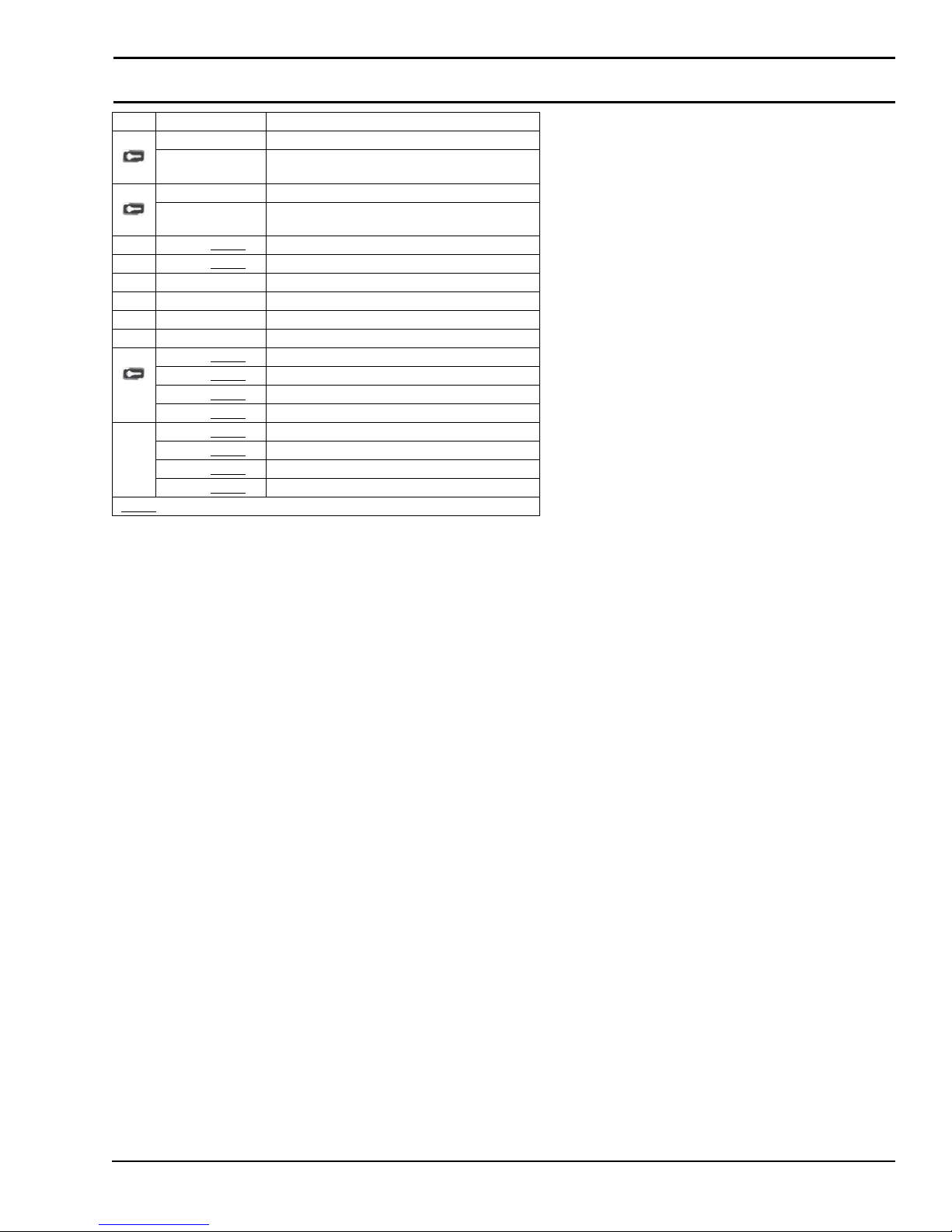
Item Part Number Description
1 834-120 Retaining Guide Set for 65 width Conveyor
834-149 Retaining Guide Set for 105 & 150 width
2 834-124 Belt Capture Guide Set for 65 width Conveyors
834-151 Belt Capture Guide Set for 105 & 150 width
3 202995-WWW
4 202995-WWW
5 203365-LH Bottom Drive Guard - Left Hand
6 203365-RH Bottom Drive Guard - Right Hand
7 910506M Button Head Screw, M5-0.80 x 6 mm
8 920812M Button Head Cap Screw, M8-1.25 x 12 mm
9 204170-WWW
203170-WWW
204071-WWW
203171-WWW
10 204072-WWW
204073-WWW
207079-WWW
204080-WWW
W= Conveyor width reference: 065, 105, 150
WW
Conveyors
Conveyors
LH Drive Plate Guard - Left Hand
RH Drive Plate Guard - Right Hand
Spindle Shaft Assembly
CE Spindle Shaft Assembly
Spindle Shaft Assembly with Auxiliary Shaft
CE Spindle Shaft Assembly with Auxiliary Shaft
Drive Tail Kit
CE Drive Tail Kit
Drive Tail with Auxiliary Shaft Kit
CE Drive Tail with Auxiliary Shaft Kit
Service Parts
851-757 Rev. A 41 Dorner Mfg. Corp.
2200 Series SmartFlex Conveyors
Page 42
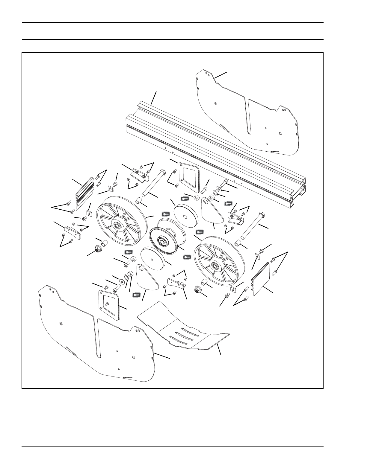
Service Parts
Weighted Take-Up
16
21
24
1
3
10
20
13
2
18
17
3
20
8
15
7
5
14
14
12
15
4
3
1
22
10
17
23
6
11
1
8
4
5
21
24
3
7
24
5
9
9
21
16
1
21
24
22
4
8
6
11
8
18
9
9
4
5
23
Dorner Mfg. Corp. 42 851-757 Rev. A
13
2200 Series SmartFlex Conveyors
19
Page 43
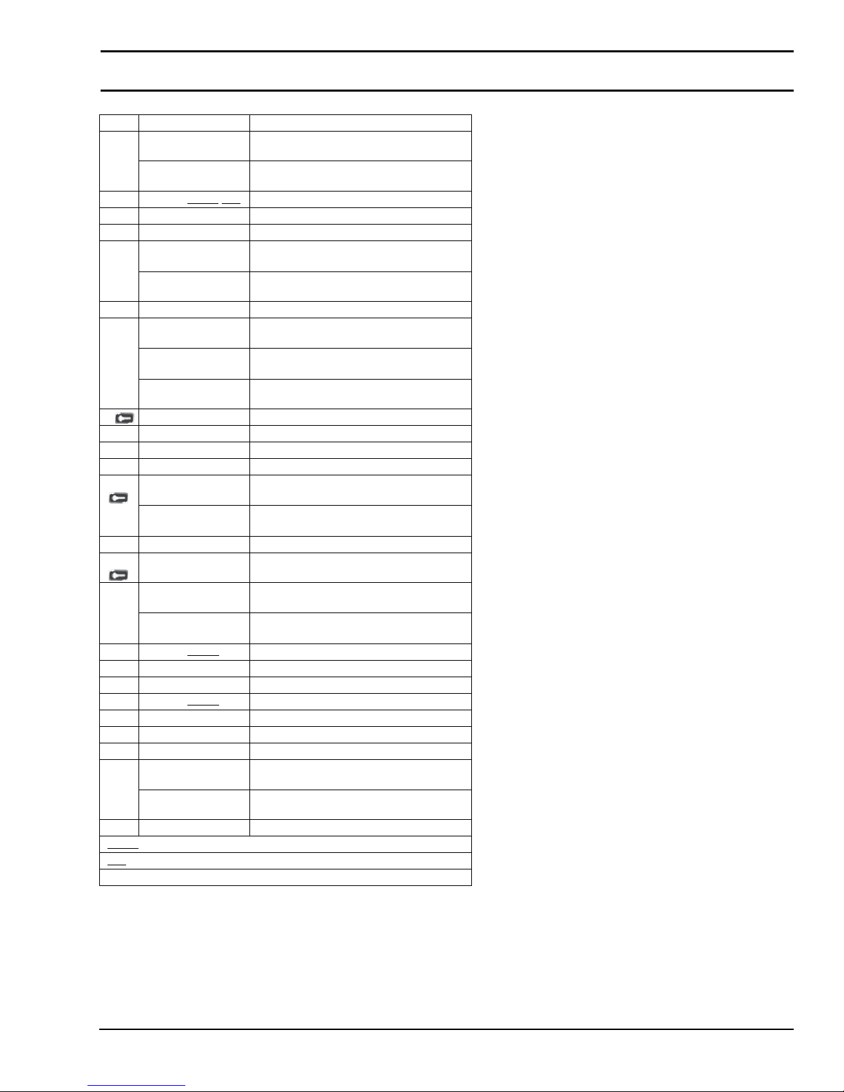
Item Part Number Description
1 834-124 Belt Capture Guide Set,
834-151 Belt Capture Guide Set,
2 203345-WWW
3 920508M Socket Head Screw, M5-.80 x 8 mm
4 990501M Hex Nut, M5-0.80
5 203455 Bushing, 0.50" x 0.75"
203456 Bushing 0.50" x 1.125"
6 807-1760 Washer
7 807-2290 Hex Bolt, 1/2-13 x 3.5"
807-2291 Hex Bolt, 1/2-13 x 5"
807-2292 Hex Bolt, 1/2-13 x 7"
8 807-2297 Nylon Spacer, 0.75" x 0.32" x 0.375"
9 834-014 Slide Nut
10 910-320 Lock Nut
11 807-2314 Spring Washer
12 201716 Idler Pulley Assembly
201756 Idler Pulley Assembly
13 203330 Weighted Take-Up Plate
14 203331 Wheel
for 65 width Conveyors
for 105 & 150 width Conveyors
-LLL Conveyor Section
for 105 width Conveyors
for 150 width Conveyors
for 65 width Conveyors
for 105 width Conveyors
for 150 width Conveyors
for 65 width Conveyors
for 105 & 150 width Conveyors
Service Parts
15 203343 Weighted Take-Up Disk for 65 & 105 width
Conveyors
203363 Weighted Take-Up Disk for 150 width
Conveyors
16 203344-WWW
17 203349 Latching Cover
18 203351 Ratchet P late
19 203457-WWW
20 920691M Low Head Cap Screw, M6-1.00 x 10 mm
21 920693M Low Head Cap Screw, M6-1.00 x 16 mm
22 920820M Socket Head Cap Screw, M8-125 x 20 mm
23 920830M Socket Head Cap Screw, M8-125 x 30 mm
920850M Socket Head Cap Screw, M8-125 x 50 mm
24 920891M Low Head Cap Screw, M8-1.25 x 10 mm
W= Conveyor width reference: 065, 105, 150
WW
= Conveyor frame section in inches: 029, 035, 047, 059
LLL
Length Example: Length = 29" LLL = 029
End Guard
Bottom Guard
for 65 & 105 width Conveyors
for 150 width Conveyors
851-757 Rev. A 43 Dorner Mfg. Corp.
2200 Series SmartFlex Conveyors
Page 44
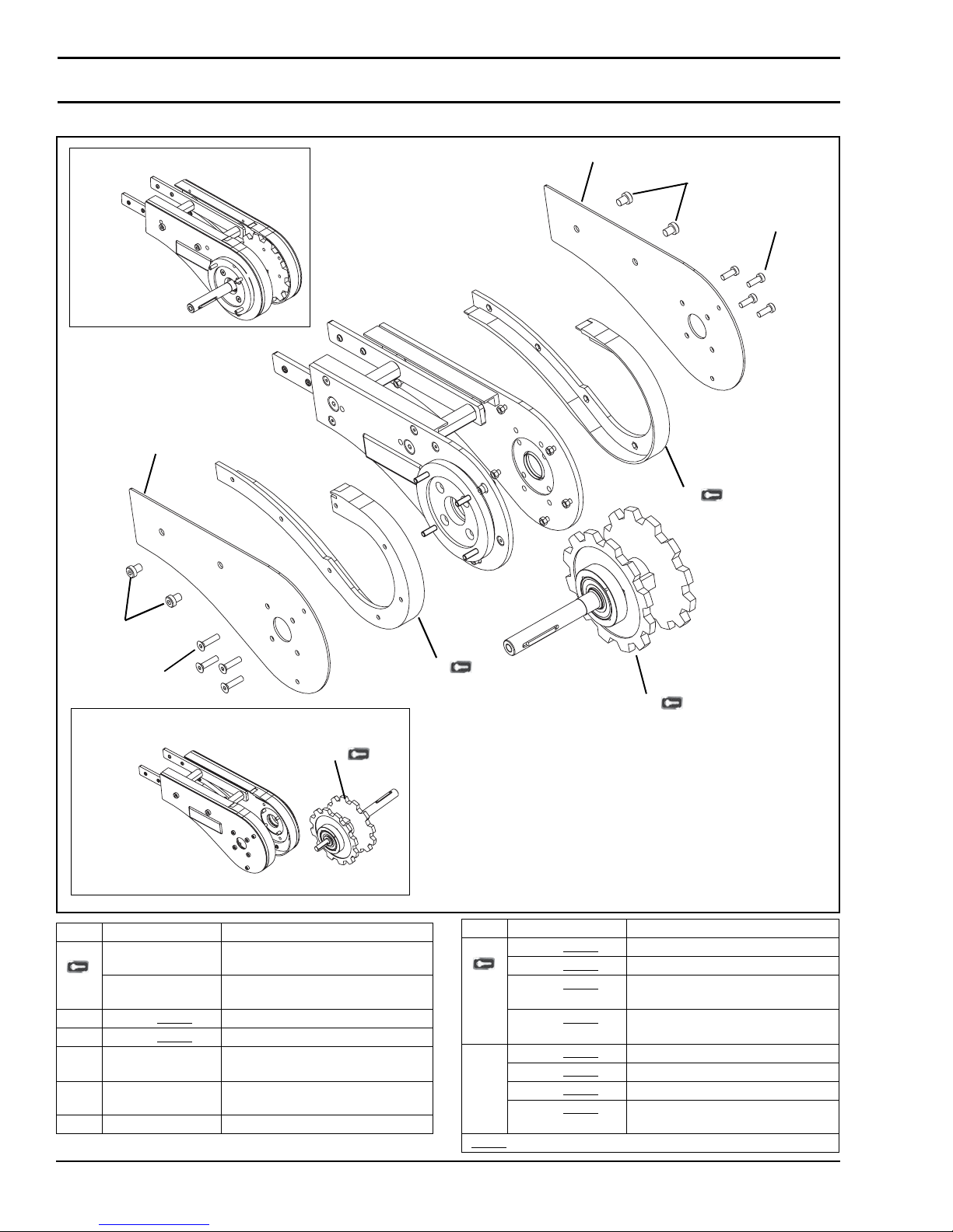
Service Parts
Weighted Take-Up Drive Tail
8 Weighted Drive Tail Kit
3
2
5
4
1
5
6
Optional Auxiliary Shaft Shown
7
Item Part Number Description
1 834-130 Retaining Guide Set for 65 width
Conveyors
834-157 Retaining Guide Set for 105 & 150
width Conveyors
2 202997-WWW
3 202997-WWW
4 920694M Button Head Cap Screw,
5 910812M Button Head Cap Screw,
6 930625M Flat Head Screw, M6-1.00 x 25 mm
LH Drive Plate Guard - Left Hand
RH Drive Plate Guard - Right Hand
M6-1.00 x 16 mm
M8-1.25 x 12 mm
1
7
Item Part Number Description
7 203168-WWW Spindle Shaft Assembly
203184-WWW
203183-WWW
203185-WWW
8 204083-WWW
204085-WWW
207084-WWW
204086-WWW
W= Conveyor width reference: 065, 105, 150
WW
CE Spindle Shaft Assembly
Spindle Shaft Assembly with
Auxiliary Shaft
CE Spindle Shaft Assembly with
Auxiliary Shaft
Drive Tail Kit
CE Drive Tail Kit
Drive Tail with Auxiliary Shaft Kit
CE Drive Tail with Auxiliary Shaft
Kit
Dorner Mfg. Corp. 44 851-757 Rev. A
2200 Series SmartFlex Conveyors
Page 45
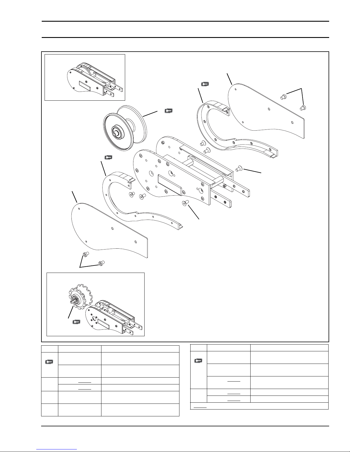
Idler Tail
6 Idler Tail Kit
Service Parts
2
1
3
5
1
4
2
4
3
Optional Auxiliary Shaft Shown
5
Item Part Number Description
1 834-130 Retaining Guide Left Hand for 65
width Conveyors
834-157 Retaining Guide Left Hand for 105
2 202997-WWW
202997-WWW
3 910812M Button Head Cap Screw,
4 920891M Flat Head Cap Screw,
& 150 width Conveyors
LH Drive Plate Guard - Left Hand
RH Drive Plate Guard - Right Hand
M8-1.00 x 12 mm
M8-1.25 x 10 mm
851-757 Rev. A 45 Dorner Mfg. Corp.
Item Part Number Description
5 201716 Idler Pulley Assembly for 65 width
201756 Idler Pulley Assembly for 105 &
203169-WWW
6 202996-WWW
204082-WWW
W= Conveyor width reference: 065, 105, 150
WW
2200 Series SmartFlex Conveyors
Conveyors
150 width Conveyors
Idler Pulley Assembly with Auxiliary
Shaft
Idler Tail Kit
Idler Tail with Auxiliary Shaft Kit
Page 46
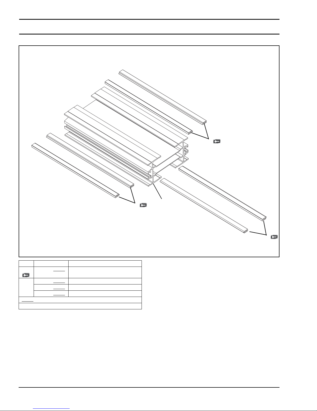
Service Parts
Frame Assembly
1
Item Part Number Description
1 834-001-LLLLL
2 834-021-LLLLL
834-041-LLLLL
834-061-LLLLL
= Part length in inches with two decimal places.
LLLLL
Length Example: Length = 95.25" LLLLL = 09525
Wear Strips
Frame for 65 width Conveyors
Frame for 105 width Conveyors
Frame for 150 width Conveyors
1
2
1
Dorner Mfg. Corp. 46 851-757 Rev. A
2200 Series SmartFlex Conveyors
Page 47
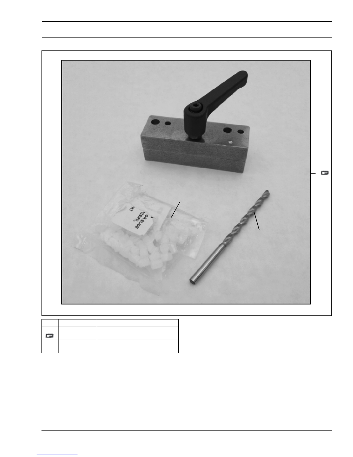
Wear Strip Replacement Tool
Service Parts
1
Item Part Number Description
1 203475 Wear Strip Replacement Tool Kit
2 834-003 Nylon Set Screws, M5 x 6 mm
3 896-1008 Drill Bit, #18, 0.1695"
2
3
851-757 Rev. A 47 Dorner Mfg. Corp.
2200 Series SmartFlex Conveyors
Page 48
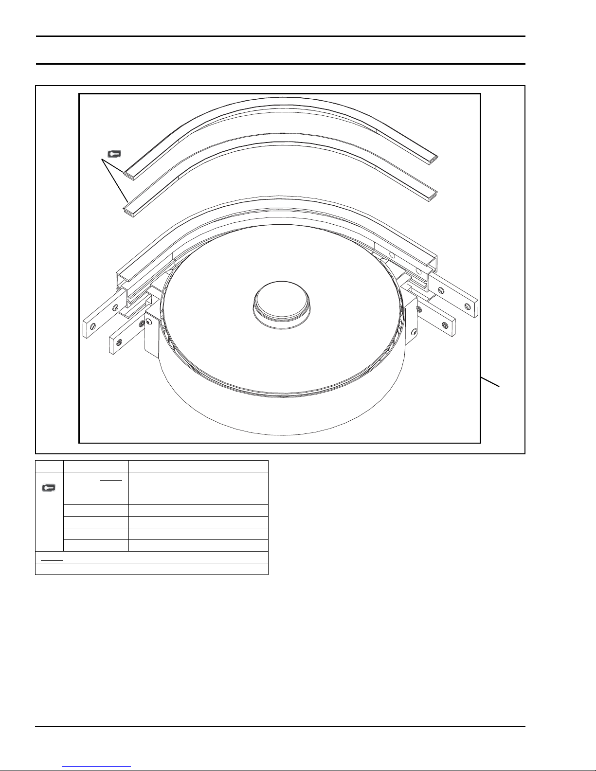
Service Parts
65 Width Curve Frame Assembly
1
Item Part Number Description
1 834-001-LLLLL
2 203458-045 45° Wheel Curve Kit
203458-090 90° Wheel Curve Kit
203458-180 180° Wheel Curve Kit
834-034 90° 500 Radius Plain Bend Curve Kit
834-035 90° 700 Radius Plain Bend Curve Kit
= Part length in inches with two decimal places.
LLLLL
Length Example: Length = 95.25" LLLLL = 09525
Wear Strips
2
Dorner Mfg. Corp. 48 851-757 Rev. A
2200 Series SmartFlex Conveyors
Page 49
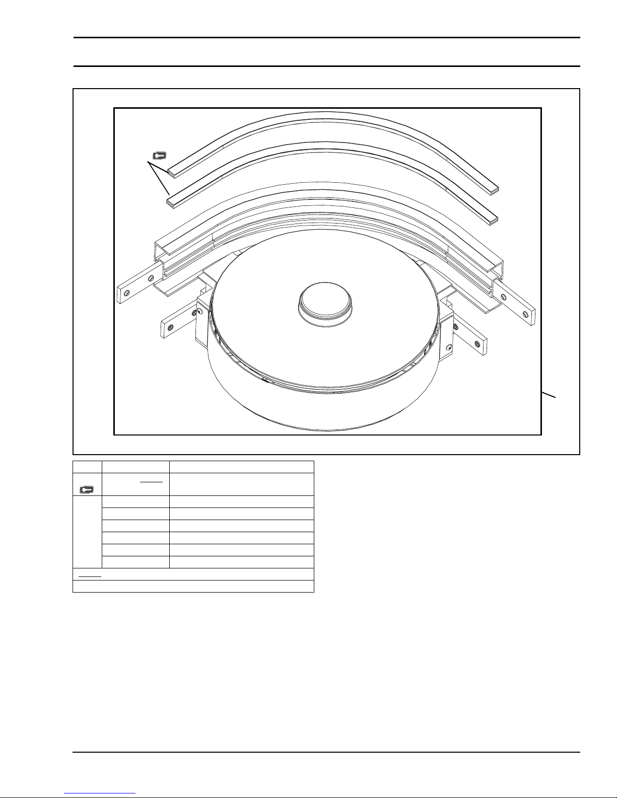
105 Width Curve Frame Assembly
1
Service Parts
Item Part Number Description
1 834-001-LLLLL
2 203459-045 45° Wheel Curve Kit
203459-090 90° Wheel Curve Kit
203459-135 135° Wheel Curve Kit
203459-180 180° Wheel Curve Kit
834-054 90° 500 Radius Plain Bend Curve Kit
834-055 90° 700 Radius Plain Bend Curve Kit
= Part length in inches with two decimal places.
LLLLL
Length Example: Length = 95.25" LLLLL = 09525
Wear Strips
2
851-757 Rev. A 49 Dorner Mfg. Corp.
2200 Series SmartFlex Conveyors
Page 50
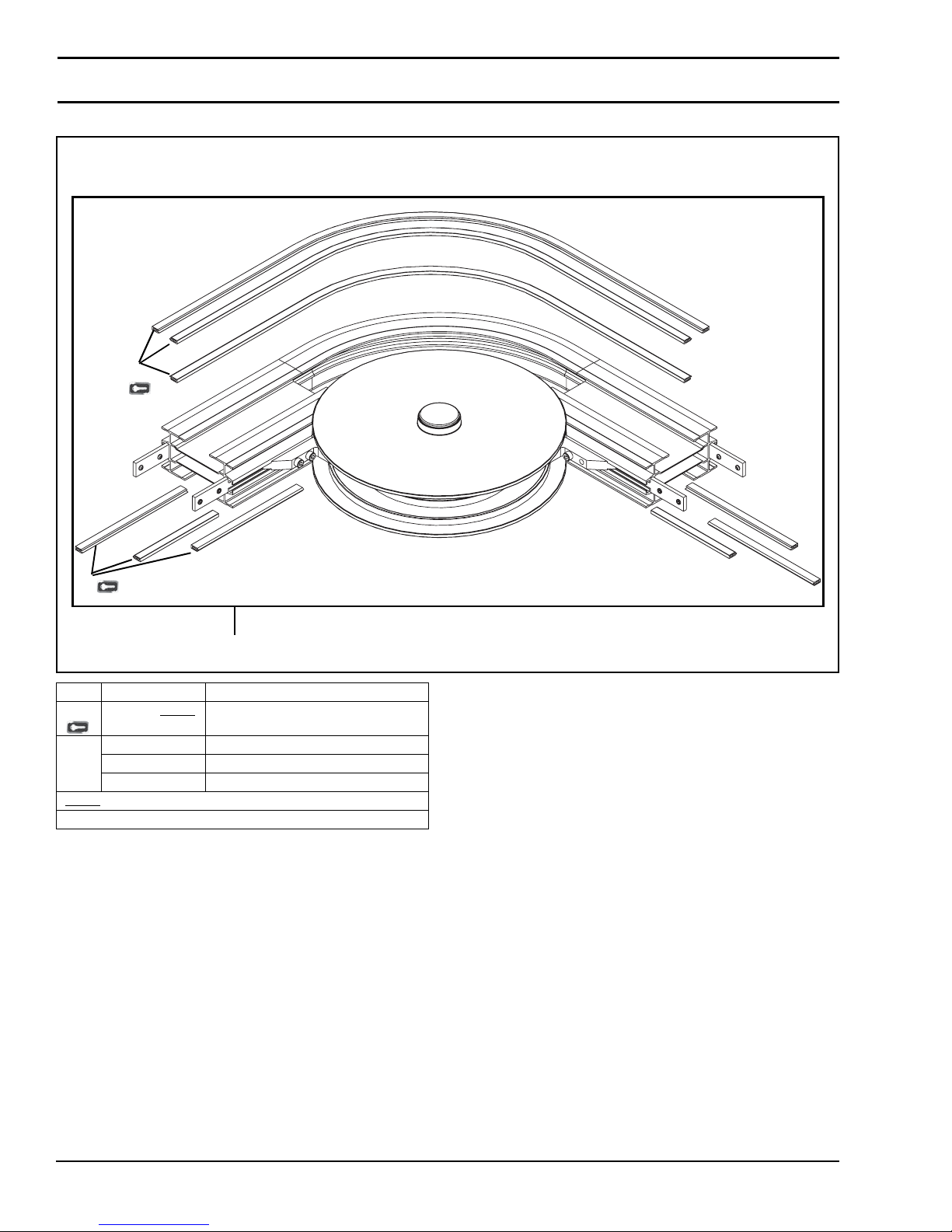
Service Parts
150 Width Curve Frame Assembly
1
1
2
Item Part Number Description
1 834-001-LLLLL
2 203460-045 45° Wheel Curve Kit
203460-090 90° Wheel Curve Kit
203460-180 180° Wheel Curve Kit
LLLLL
= Part length in inches with two decimal places.
Length Example: Length = 95.25" LLLLL = 09525
Wear Strips
Dorner Mfg. Corp. 50 851-757 Rev. A
2200 Series SmartFlex Conveyors
Page 51
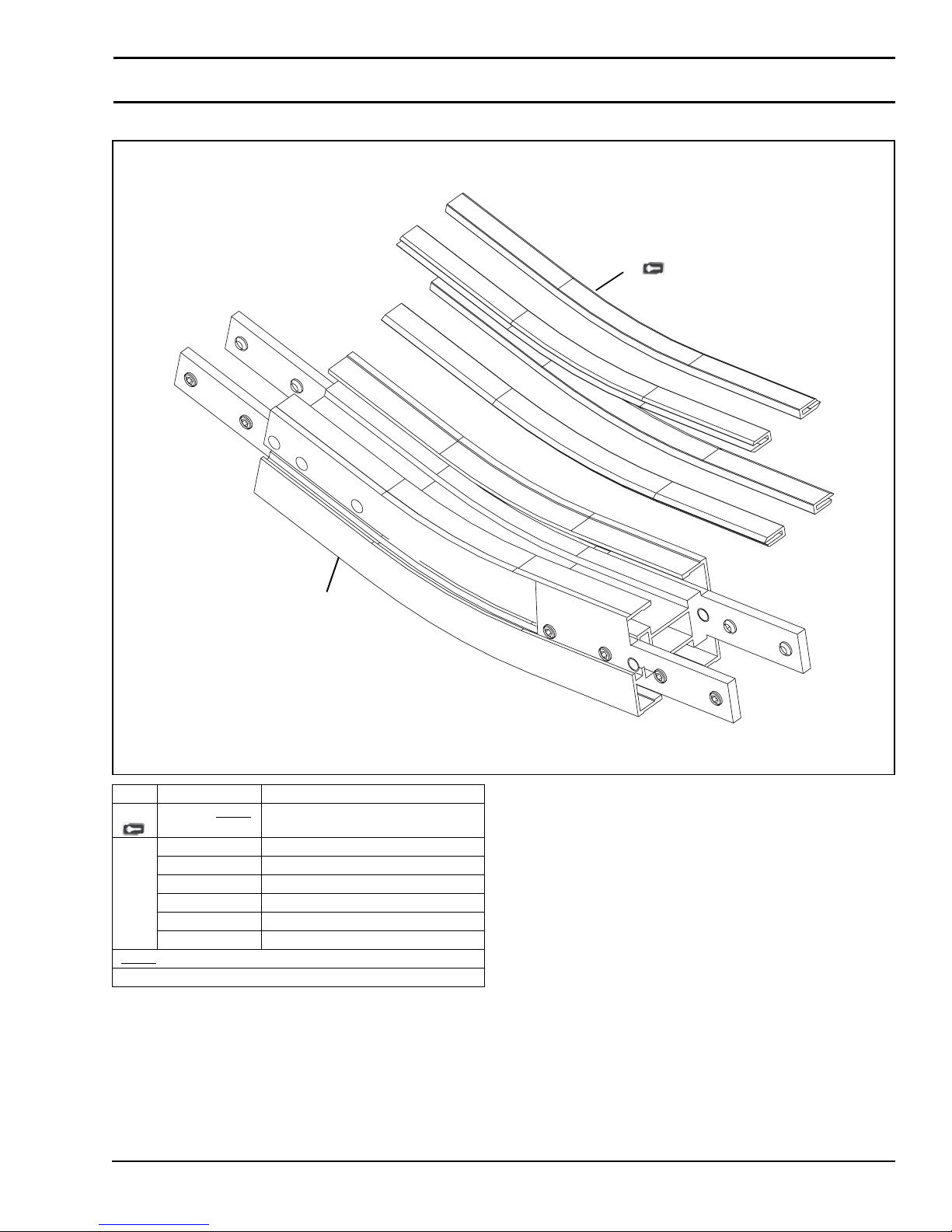
65 Width Knuckle Frame Assembly
Service Parts
1
2
Item Part Number Description
1 834-001-LLLLL
2 834-030 5° Knuckle Kit
834-036 7° Knuckle Kit
834-031 10° Knuckle Kit
834-037 15° Knuckle Kit
834-032 20° Knuckle Kit
834-033 30° Knuckle Kit
= Part length in inches with two decimal places.
LLLLL
Length Example: Length = 95.25" LLLLL = 09525
Wear Strips
851-757 Rev. A 51 Dorner Mfg. Corp.
2200 Series SmartFlex Conveyors
Page 52
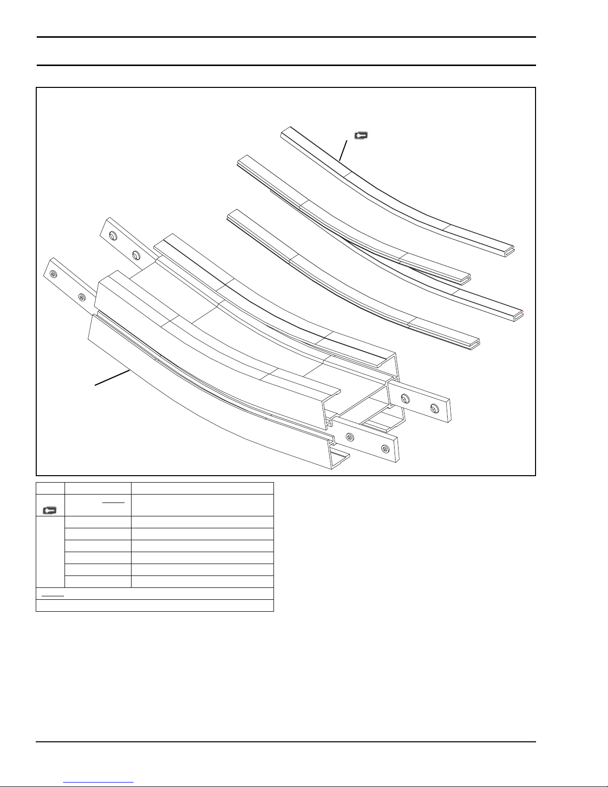
Service Parts
105 Width Knuckle Frame Assembly
1
2
Item Part Number Description
1 834-001-LLLLL
2 834-050 5° Knuckle Kit
834-056 7° Knuckle Kit
834-051 10° Knuckle Kit
834-057 15° Knuckle Kit
834-052 20° Knuckle Kit
834-053 30° Knuckle Kit
= Part length in inches with two decimal places.
LLLLL
Length Example: Length = 95.25" LLLLL = 09525
Wear Strips
Dorner Mfg. Corp. 52 851-757 Rev. A
2200 Series SmartFlex Conveyors
Page 53
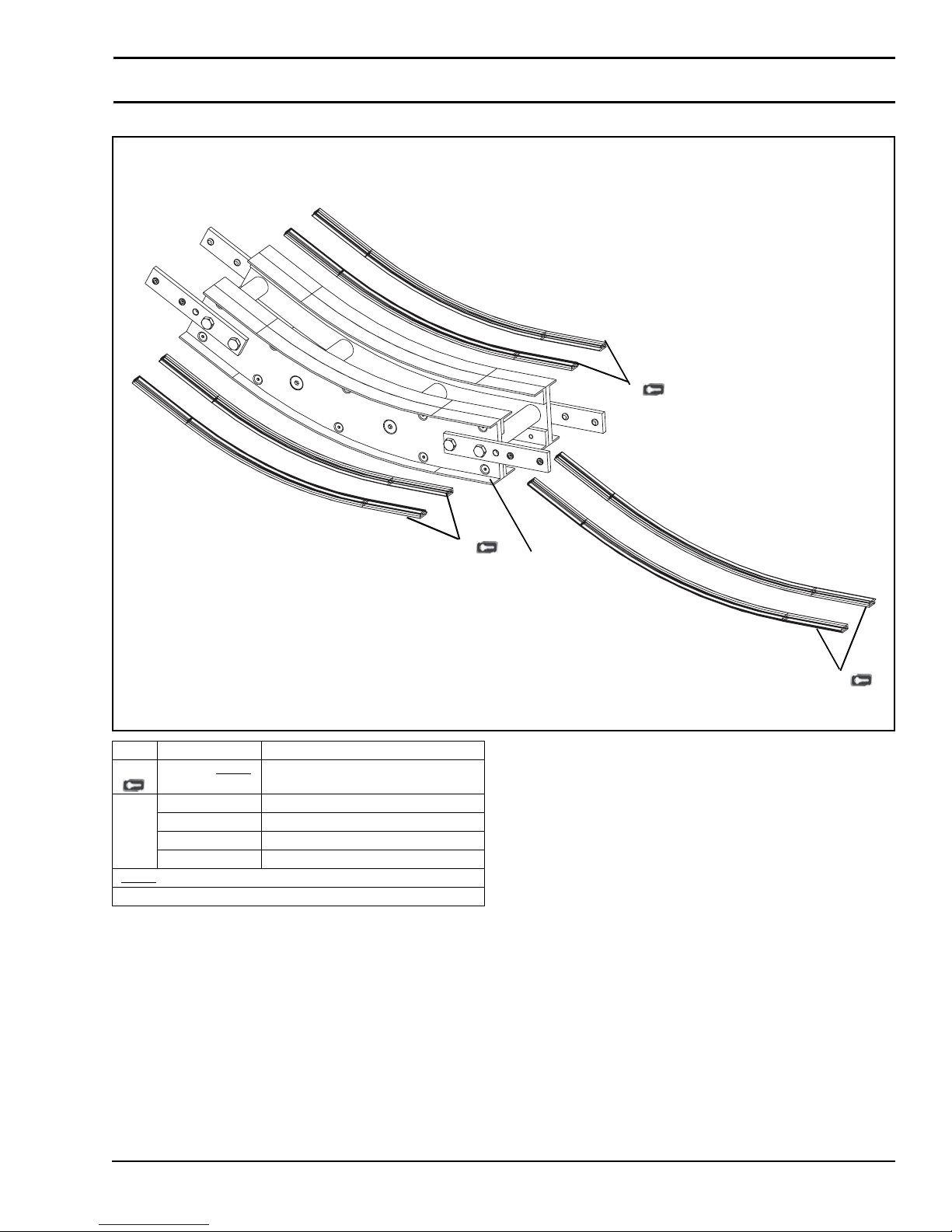
150 Width Knuckle Frame Assembly
Service Parts
1
Item Part Number Description
1 834-001-LLLLL
2 834-070 5° Knuckle Kit
834-071 10° Knuckle Kit
834-072 20° Knuckle Kit
834-073 30° Knuckle Kit
= Part length in inches with two decimal places.
LLLLL
Length Example: Length = 95.25" LLLLL = 09525
Wear Strips
1
2
1
851-757 Rev. A 53 Dorner Mfg. Corp.
2200 Series SmartFlex Conveyors
Page 54
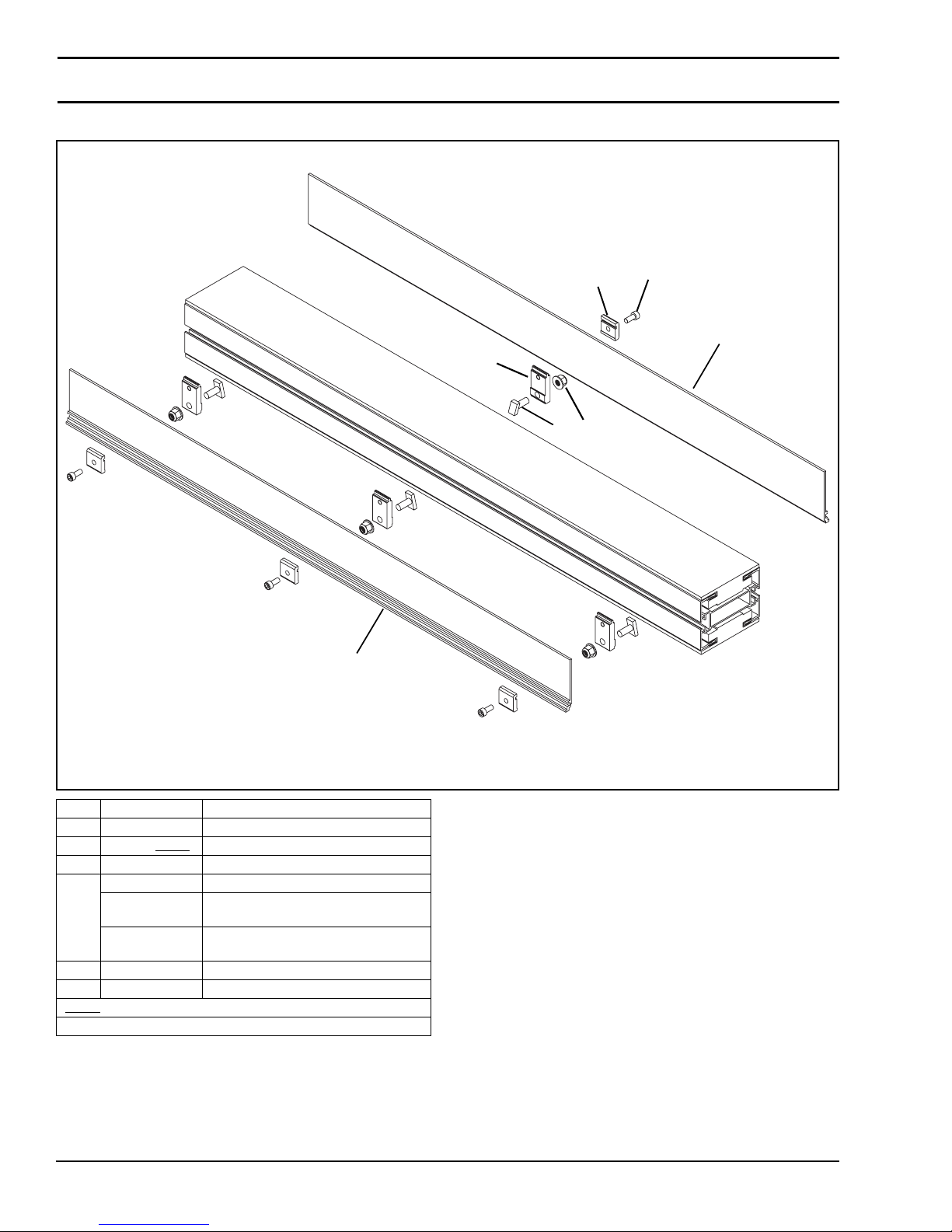
Service Parts
04 3" High Sides for Straight Modules
3
4
1
6
2
5
2
Item Part Number Description
1 834-007 Stud, M8 x 20 mm
2 204127-LLLLL
3 204566 Mounting Clip
4 210829 Guide Clip Adapter
210831 Guide Clip Adapter
210836 Guide Clip Adapter
5 920614M Socket Head Screw, M6-1.00 x 14 mm
6 990812M Hex Nut, M8-1.25
= Part length in inches with two decimal places.
LLLLL
Length Example: Length = 95.25" LLLLL = 09525
3" High Side
for Tail Mount Only
for Roller Transfer Tail Mount Only
Dorner Mfg. Corp. 54 851-757 Rev. A
2200 Series SmartFlex Conveyors
Page 55
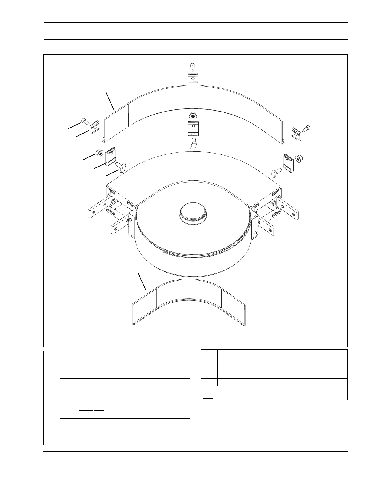
04 3" High Sides for Curve Modules
2
6
4
7
5
1
Service Parts
3
Item Part Number Description
1 834-007 Stud, M8 x 20 mm
2 204134-WWW
204336-WWW
204340-WWW
3 204136-WWW
204335-WWW
204339-WWW
-AAA 3" High Side for Wheel Bend Curves Outside Edge
-AAA 3" High Side for 500R Plain Bend
Curves - Outside Edge
-AAA 3" High Side for 700R Plain Bend
Curves - Outside Edge
-AAA 3" High Side for Wheel Bend Curves Inside Edge
-AAA 3" High Side for 500R Plain Bend
Curves - Inside Edge
-AAA 3" High Side for 700R Plain Bend
Curves - Inside Edge
Item Part Number Description
4 204566 Mounting Clip
5 210829 Clip Guide Adapter
6 920614M Socket Head Screw, M6-1.00 x 14 mm
7 990812M Hex Nut, M8-1.25
= Conveyor width reference: 065, 105, 150
WWW
= Angle of curve: 045, 090, 135, 180
AAA
851-757 Rev. A 55 Dorner Mfg. Corp.
2200 Series SmartFlex Conveyors
Page 56
Service Parts
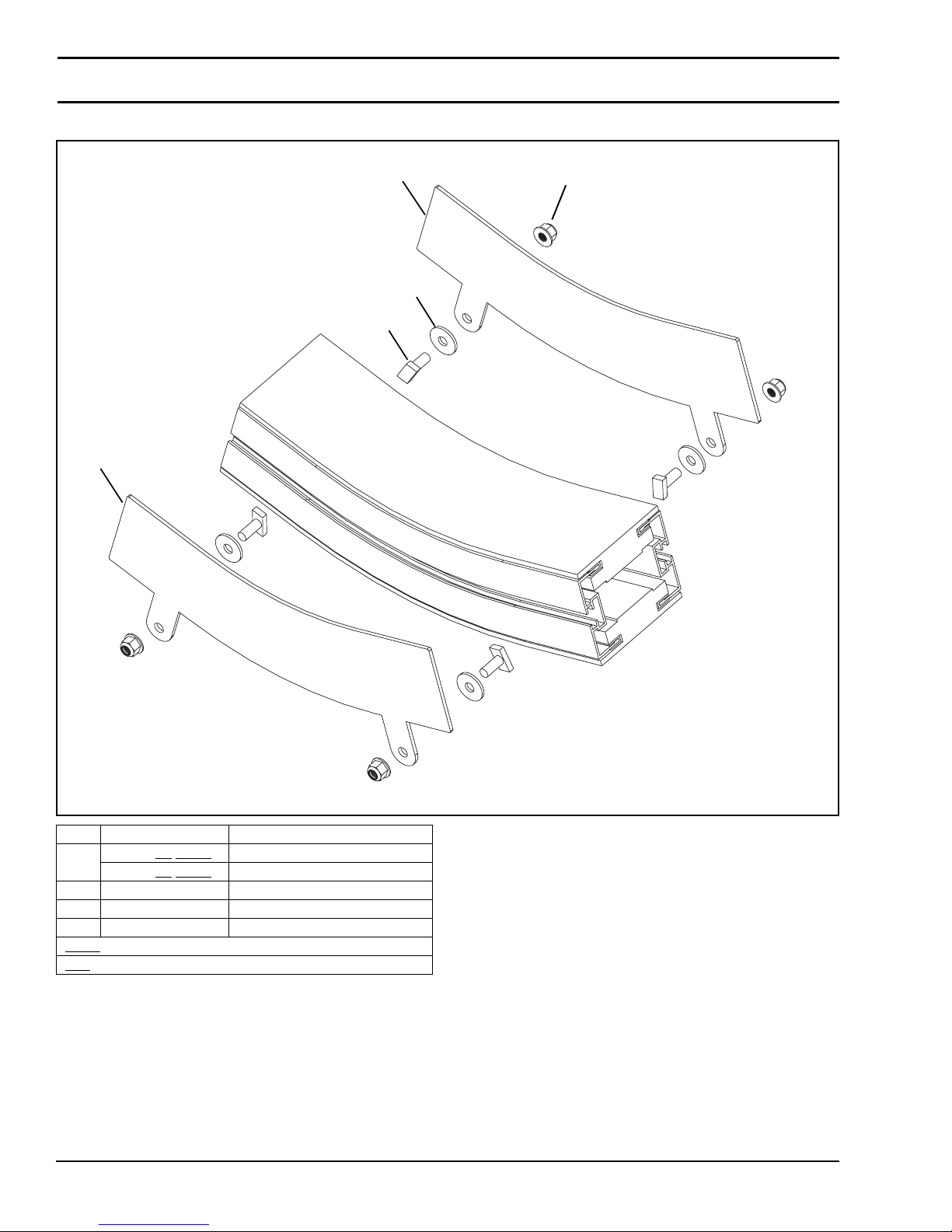
04 3" High Sides for Incline/Decline Modules
1
4
2
1
3
Item Part Number Description
1 204144-AA
204174-AA
2 834-007 Stud, M8 x 20 mm
3 990812M Hex Nut, M8-1.25
4 204145 Spacer
= Conveyor width reference: 065, 105, 150
WWW
= Angle of curve: 045, 090, 135, 180
AAA
-WWW Guide Plate for Lower knuckle
-WWW Guide Plate for Upper Knuckle
Dorner Mfg. Corp. 56 851-757 Rev. A
2200 Series SmartFlex Conveyors
Page 57
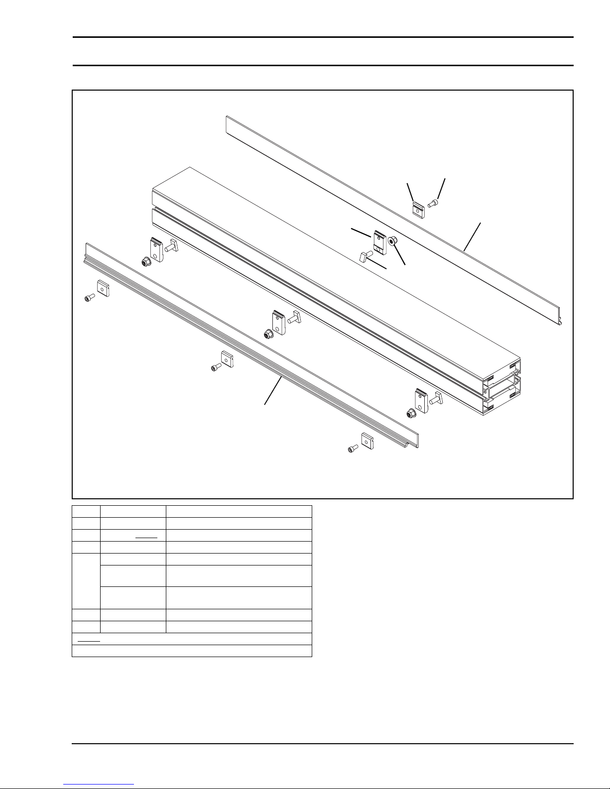
05 1.50" High Sides for Straight Modules
Service Parts
3
4
1
6
2
5
2
Item Part Number Description
1 834-007 Stud, M8 x 20 mm
2 204172-LLLLL
3 204566 Mounting Clip
4 210829 Guide Clip Adapter
210831 Guide Clip Adapter
210836 Guide Clip Adapter
5 920614M Socket Head Screw, M6-1.00 x 14 mm
6 990812M Hex Nut, M8-1.25
= Part length in inches with two decimal places.
LLLLL
Length Example: Length = 95.25" LLLLL = 09525
1.50" High Side
for Tail Mount Only
for Roller Transfer Tail Mount Only
851-757 Rev. A 57 Dorner Mfg. Corp.
2200 Series SmartFlex Conveyors
Page 58
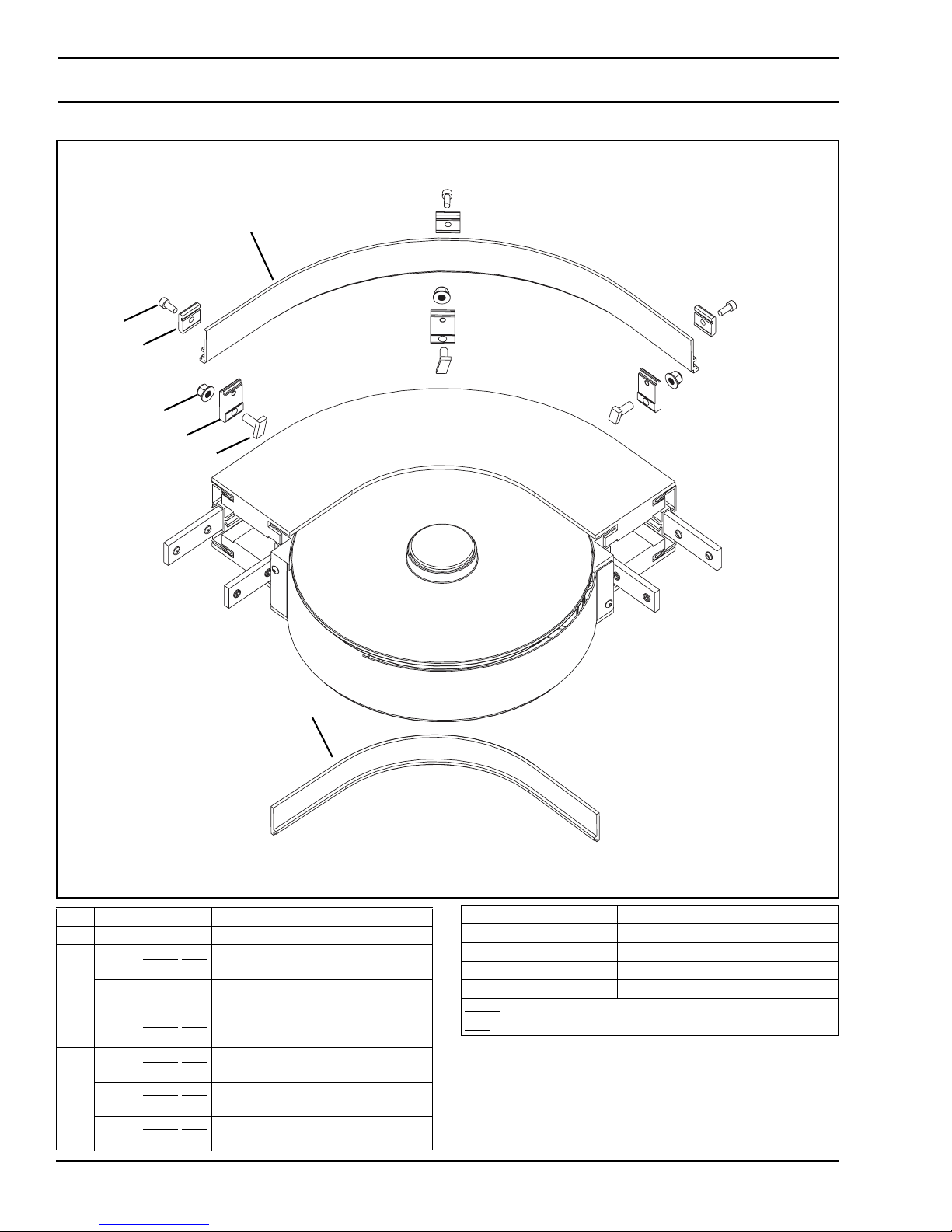
Service Parts
05 1.50" High Sides for Curve Modules
2
6
4
7
5
1
3
Item Part Number Description
1 834-007 Stud, M8 x 20 mm
2 204135-WWW
204334-WWW
204338-WWW
3 204137-WWW
204333-WWW
204337-WWW
-AAA 1.50" High Side for Wheel Bend
Curves - Outside Edge
-AAA 1.50" High Side for 500R Plain Bend
Curves - Outside Edge
-AAA 1.50" High Side for 700R Plain Bend
Curves - Outside Edge
-AAA 1.50" High Side for Wheel Bend
Curves - Inside Edge
-AAA 1.50" High Side for 500R Plain Bend
Curves - Inside Edge
-AAA 1.50" High Side for 700R Plain Bend
Curves - Inside Edge
Item Part Number Description
4 204566 Mounting Clip
5 210829 Clip Guide Adapter
6 920614M Socket Head Screw, M6-1.00 x 14 mm
7 990812M Hex Nut, M8-1.25
= Conveyor width reference: 065, 105, 150
WWW
= Angle of curve: 045, 090, 135, 180
AAA
Dorner Mfg. Corp. 58 851-757 Rev. A
2200 Series SmartFlex Conveyors
Page 59
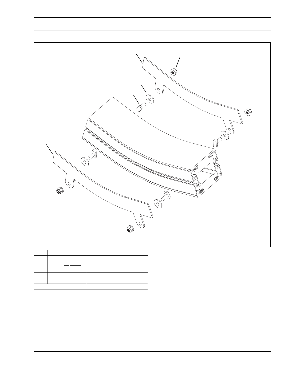
05 1.50" High Sides for Incline/Decline Modules
Service Parts
1
4
2
1
3
Item Part Number Description
1 204342-AA
204343-AA
2 834-007 Stud, M8 x 20 mm
3 990812M Hex Nut, M8-1.25
4 204145 Spacer
= Conveyor width reference: 065, 105, 150
WWW
= Angle of curve: 045, 090, 135, 180
AAA
-WWW Guide Plate for Lower knuckle
-WWW Guide Plate for Upper Knuckle
851-757 Rev. A 59 Dorner Mfg. Corp.
2200 Series SmartFlex Conveyors
Page 60
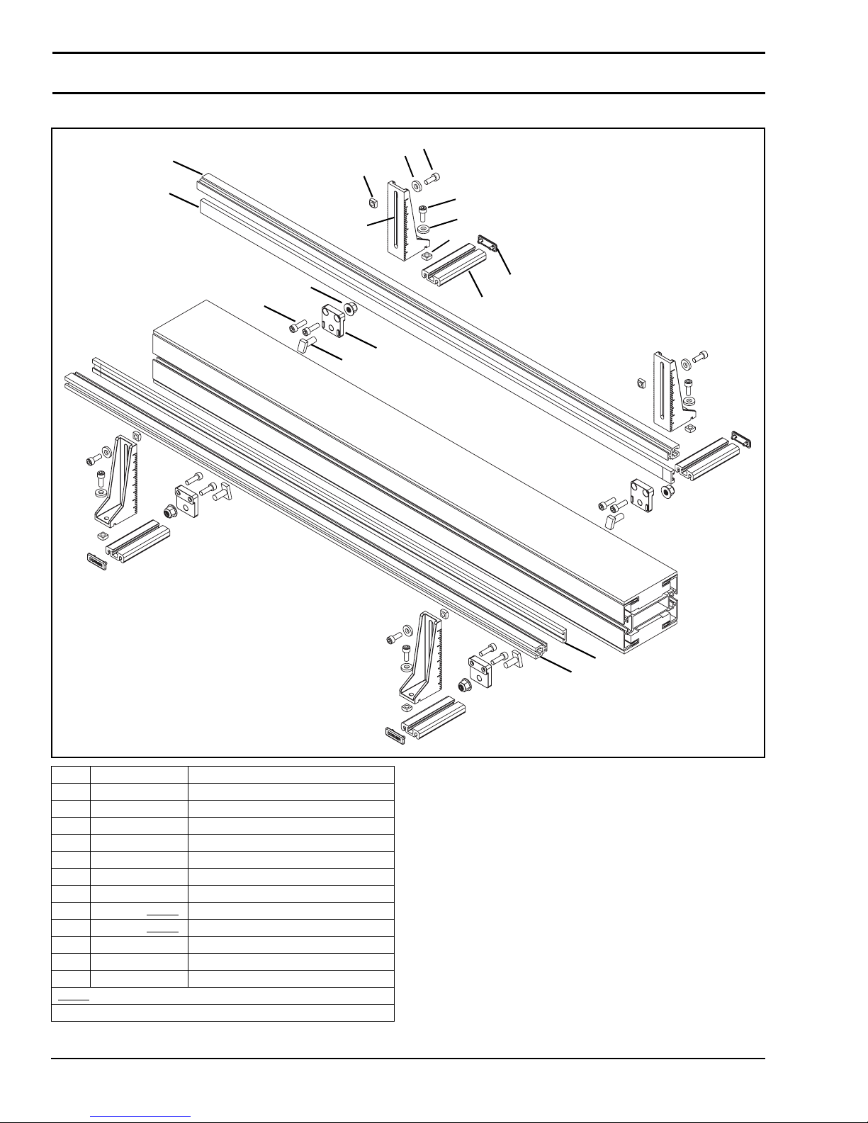
Service Parts
13 Fully Adjustable Guiding for Straight Modules
10
9
8
7
1
10
4
7
1
11
12
6
3
5
2
8
9
Item Part Number Description
1 807-920 Square Nut, M6-1.0
2 834-007 Stud, M8 x 20 mm
3 210846-00353 Extrusion Base
4 210847 Mounting Bracket
5 210848 Mounting Block
6 210849 Cap
7 605279P Washer
8 614068P-LLLLL
9 636975P-LLLLL
10 920616M Socket Head Screw, M6-1.00 x 16 mm
11 920516M Socket Head Screw, M5-0.80 x 16 mm
12 990812M Hex Nut, M8-1.25
= Part length in inches with two decimal places.
LLLLL
Length Example: Length = 95.25" LLLLL = 09525
Guiding
Guide Rail
Dorner Mfg. Corp. 60 851-757 Rev. A
2200 Series SmartFlex Conveyors
Page 61
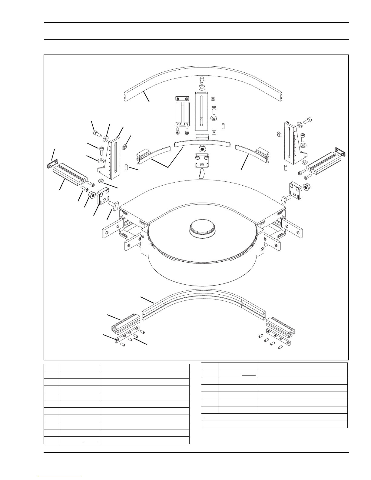
13 Fully Adjustable Guiding for Curve Modules
10
Service Parts
12
9
4
1
6
12
9
16
3
1
7
7
13
15
5
2
11
8
Item Part Number Description
1 807-920 Square Nut, M6-1.0
2 834-007 Stud, M8 x 20 mm
3 210846-00353 Extrusion Base
4 210847 Mounting Bracket
5 210848 Mounting Block
6 210849 Cap
7 203494 Guide Support
8 210913 Nut Bar
9 605279P Washer
10 614068P-LLLLL
Guiding
851-757 Rev. A 61 Dorner Mfg. Corp.
10
14
2200 Series SmartFlex Conveyors
Item Part Number Description
11 636975P-LLLLL Guide Rail
12 920616M Socket Head Scr ew, M6-1.00 x 16 mm
13 920516M Socket Head Scr ew, M5-0.80 x 16 mm
14 930510M Flat Head Screw, M5-0.80 x 10 mm
15 990812M Hex Nut, M8-1.25
16 913-051 Roll Pin
= Part length in inches with two decimal places.
LLLLL
Length Example: Length = 95.25" LLLLL = 09525
Page 62
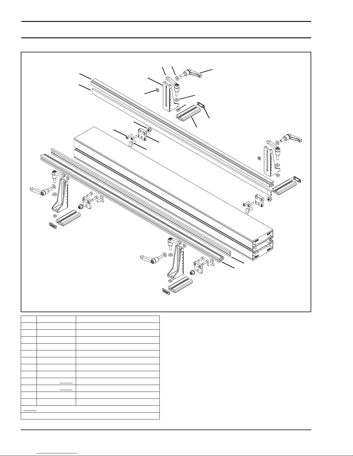
Service Parts
14 Tool-Less Fully Adjustable Guiding for Straight Modules
8
10
1
5
9
1
11
12
2
8
2
7
4
6
3
Item Part Number Description
1 807-2272 Handle
2 807-920 Square Nut, M6-1.0
3 834-007 Stud, M8 x 20 mm
4 210846-00353 Extrusion Base
5 210847 Mounting Bracket
6 210848 Mounting Block
7 210849 Cap
8 605279P Washer
9 614068P-LLLLL
10 636975P-LLLLL
11 920516M Socket Head Screw, M5-0.80 x 16 mm
12 990812M Hex Nut, M8-1.25
= Part length in inches with two decimal places.
LLLLL
Length Example: Length = 95.25" LLLLL = 09525
Guiding
Guide Rail
9
10
Dorner Mfg. Corp. 62 851-757 Rev. A
2200 Series SmartFlex Conveyors
Page 63
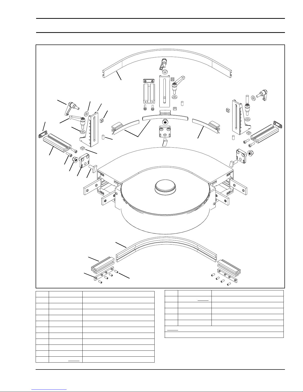
14 Tool-Less Fully Adjustable Guiding for Curve Modules
11
Service Parts
1
10
5
2
7
1
10
16
4
2
8
8
13
15
6
3
11
12
9
Item Part Number Description
1 807-2272 Handle
2 807-920 Square Nut, M6-1.0
3 834-007 Stud, M8 x 20 mm
4 210846-00353 Extrusion Base
5 210847 Mounting Bracket
6 210848 Mounting Block
7 210849 Cap
8 203494 Guide Support
9 210913 Nut Bar
10 605279P Washer
11 614068P-LLLLL
Guiding
851-757 Rev. A 63 Dorner Mfg. Corp.
14
Item Part Number Description
12 636975P-LLLLL Guide Rail
13 920516M Socket Head Screw, M5-0.80 x 16 mm
14 930510M Flat Head Screw, M5-0.80 x 10 mm
15 990812M Hex Nut, M8-1.25
16 913-051 Roll Pin
= Part length in inches with two decimal places.
LLLLL
Length Example: Length = 95.25" LLLLL = 09525
2200 Series SmartFlex Conveyors
Page 64
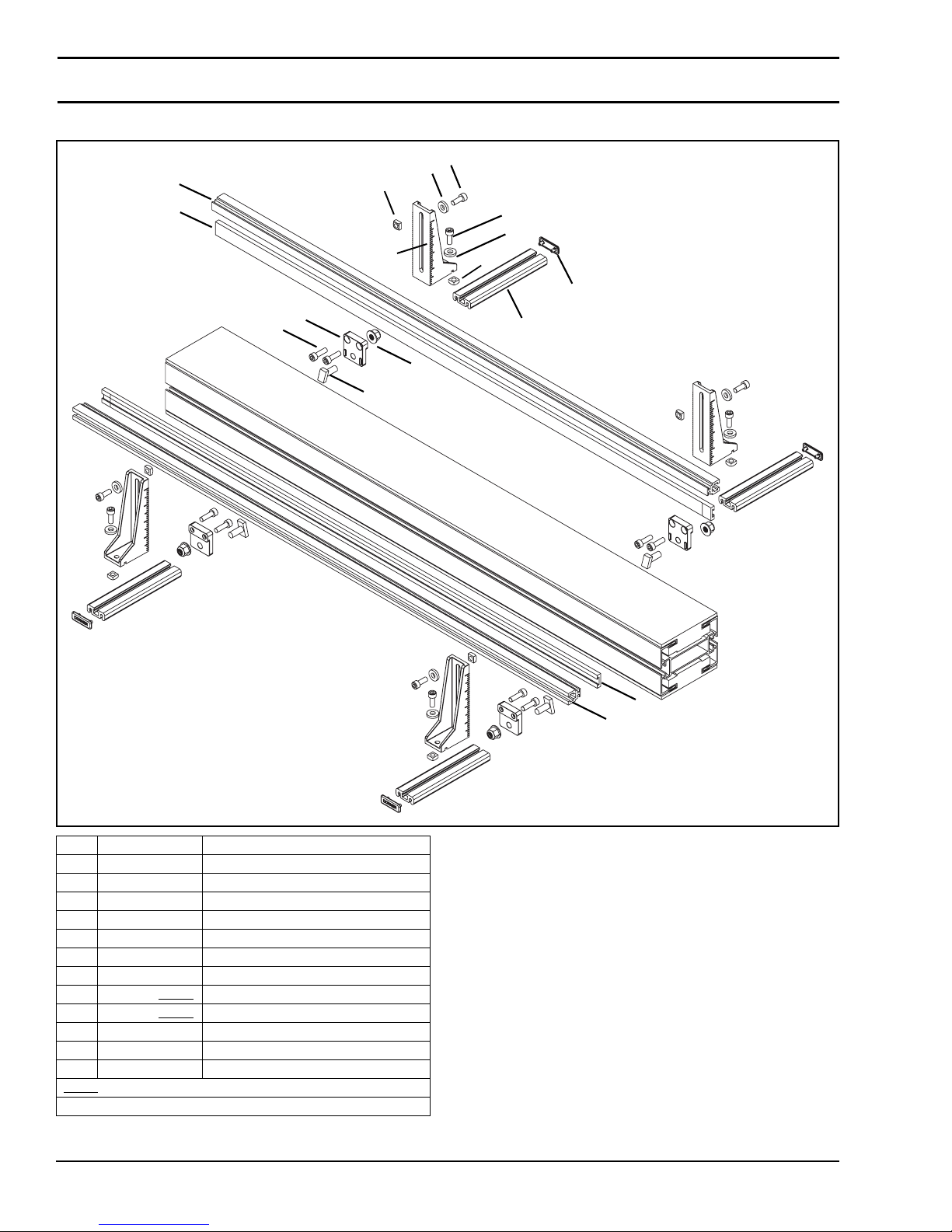
Service Parts
16 Gull Wing Guiding for Straight Modules
10
9
1
8
7
4
10
7
1
11
12
6
3
5
2
8
9
Item Part Number Description
1 807-920 Square Nut, M6-1.0
2 834-007 Stud, M8 x 20 mm
3 210846-00600 Extrusion Base
4 210847 Mounting Bracket
5 210848 Mounting Block
6 210849 Cap
7 605279P Washer
8 614068P-LLLLL
9 636975P-LLLLL
10 920616M Socket Head Screw, M6-1.00 x 16 mm
11 920516M Socket Head Screw, M5-0.80 x 16 mm
12 990812M Hex Nut, M8-1.25
= Part length in inches with two decimal places.
LLLLL
Length Example: Length = 95.25" LLLLL = 09525
Guiding
Guide Rail
Dorner Mfg. Corp. 64 851-757 Rev. A
2200 Series SmartFlex Conveyors
Page 65
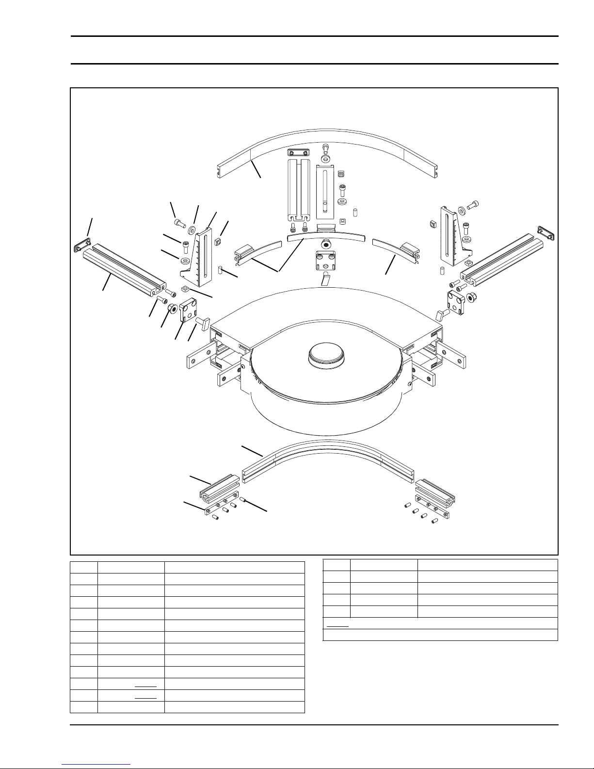
16 Gull Wing Guiding for Curve Modules
10
12
6
12
9
9
4
1
Service Parts
16
3
1
7
7
13
15
5
2
10
11
8
14
Item Part Number Description
1 807-920 Square Nut, M6-1.0
2 834-007 Stud, M8 x 20 mm
3 210846-00600 Extrusion Base
4 210847 Mounting Bracket
5 210848 Mounting Block
6 210849 Cap
7 203494 Guide Support
8 210913 Nut Bar
9 605279P Washer
10 614068P-LLLLL
11 636975P-LLLLL
12 920616M Socket Head Screw, M6-1.00 x 16 mm
Guiding
Guide Rail
851-757 Rev. A 65 Dorner Mfg. Corp.
Item Part Number Description
13 920516M Socket Head Screw, M5-0.80 x 16 mm
14 930510M Flat Head Screw, M5-0.80 x 10 mm
15 990812M Hex Nut, M8-1.25
16 913-051 Roll Pin
= Part length in inches with two decimal places.
LLLLL
Length Example: Length = 95.25" LLLLL = 09525
2200 Series SmartFlex Conveyors
Page 66
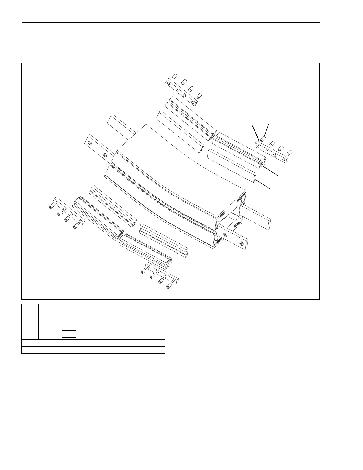
Service Parts
#13 & #14 - Adjustable Guiding and #16 - Gull Wing Guiding for Incline/
Decline Modules
1
2
4
3
Item Part Number Description
1 210913 Nut Bar
2 930510M Flat Head Screw, M5-0.80 x 10 mm
3 614068P-LLLLL
4 636975P-LLLLL
= Part length in inches with two decimal places.
LLLLL
Length Example: Length = 95.25" LLLLL = 09525
Guiding
Guide Rail
Dorner Mfg. Corp. 66 851-757 Rev. A
2200 Series SmartFlex Conveyors
Page 67
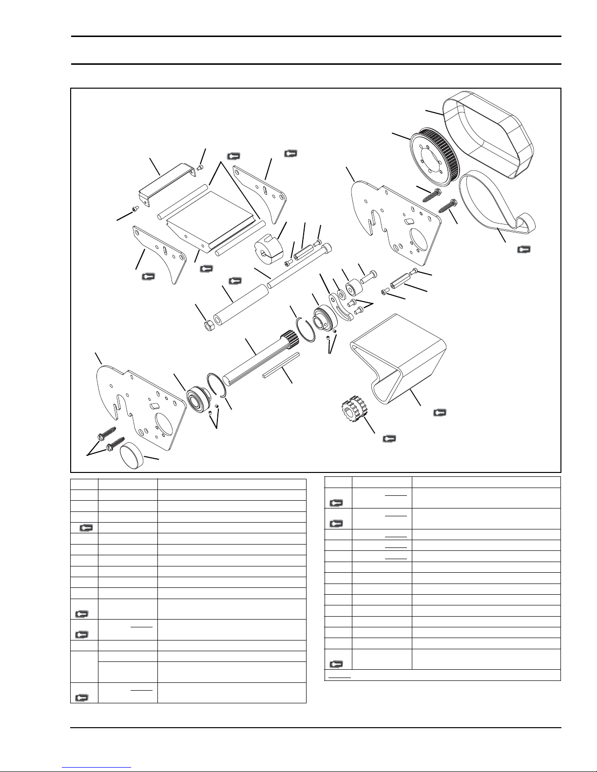
Power Transfer
20
23
11
14
Service Parts
21
9
23
15
12
17
28
18
2
27
11
14
3
7
8
24
24
3
29
26
1
13
22
2
6
25
24
24
7
10
6
10
3
Item Part Number Description
1 802-046 Cam Bearing
2 802-110 Bear ing
3 807-1884 Sheet Metal Screws, #14 x 1.25
4 807-2009 Sprocket
5 807-2285 Cover
6 807-2286 Retaining Ring
7807-2287 Hex Post
8811-289 Bushing
9 811-559 Pulley
10 907-115 Socket Head Set Screw, #10-32 x 0.19
11 203229 Side Guide Plate
12 203230-WWW
13 203231 Timing Belt Tensioner
14 203243 Side Plate for 65 width Conveyors
203244 Side Plate for 105
15 203247-WWW
5
Wear Bar
& 150 width Conveyors
Wear Rod
19
16
4
Item Part Number Description
16 203249-WWW Power Transfer Belt
17 203263-WWW
18 203264-WWW
19 203267-WWW
20 203364-WWW
21 350505 Power Transfer Cover
22 605280P Washer
23 920406M Socket Head Screw, M4-0. 70 x 6 mm
24 920591M Low Head Cap Screw, M5-0.80 x 10 mm
25 920691M Low Head Cap Screw, M6-1.00 x 10 mm
26 920895M Low Head Cap Screw, M8-1.25 x 25 mm
27 9210130M Socket Head Screw, M10-0.50 x 130 mm
28 991011M Hex Nut, M10-1.50
29 814-065 Timing Belt 5 mm x 15 mm
WW
W= Conveyor width reference: 065, 105, 150
Tensioner Tube
Shaft Assembly
Square Key, 3/16” x 105 mm
Tensioner Plate
851-757 Rev. A 67 Dorner Mfg. Corp.
2200 Series SmartFlex Conveyors
Page 68
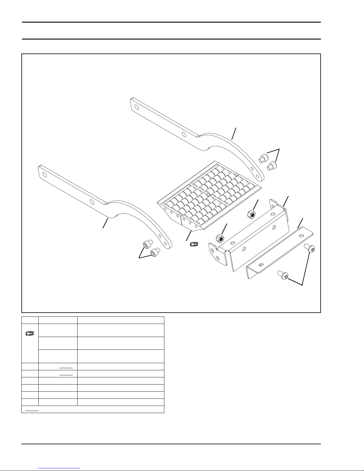
Service Parts
Transfer Roller
4
6
4
6
Item Part Number Description
1 807-1829 Transfer Roller
807-1830 Transfer Roller
807-1829 Transfer Roller
2 203068-WWW
3 203069-WWW
4 204138 Roller Bar
5 910612M Button Head Screw, M6-1.00 x 12 mm
6 920606M Socket Head Screw, M6-1.00 x 6 mm
7 990602M Hex Nut
W= Conveyor width reference: 065, 105, 150
WW
for 65 Width Conveyors (2x)
for 105 Width Conveyors (2x)
for 150 Width Conveyors (4x)
Bracket
Extension Bracket
7
2
3
7
1
5
Dorner Mfg. Corp. 68 851-757 Rev. A
2200 Series SmartFlex Conveyors
Page 69
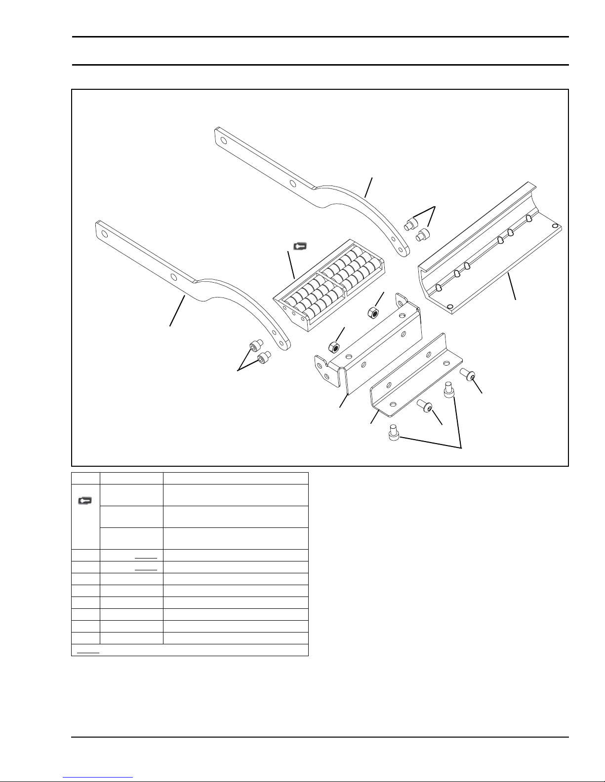
Transfer Roller to 2200 Series Conveyor
1
Service Parts
4
6
7
8
4
6
Item Part Number Description
1 807-1829 Transfer Roller
807-1830 Transfer Roller
807-1829 Transfer Roller
2 203068-WWW
3 203069-WWW
4 204138 Roller Bar
5 910612M Button Head Screw, M6-1.00 x 12 mm
6 920606M Socket Head Screw, M6-1.00 x 6 mm
7 990602M Hex Nut
8 204140 Transfer Plate
9 920610M Socket Head Screw, M6-1.00 x 10 mm
W= Conveyor width reference: 065, 105, 150
WW
for 65 Width Conveyors (1x)
for 105 W idth Conveyors (1x)
for 150 W idth Conveyors (2x)
Bracket
Extension Bracket
7
5
2
3
5
9
851-757 Rev. A 69 Dorner Mfg. Corp.
2200 Series SmartFlex Conveyors
Page 70
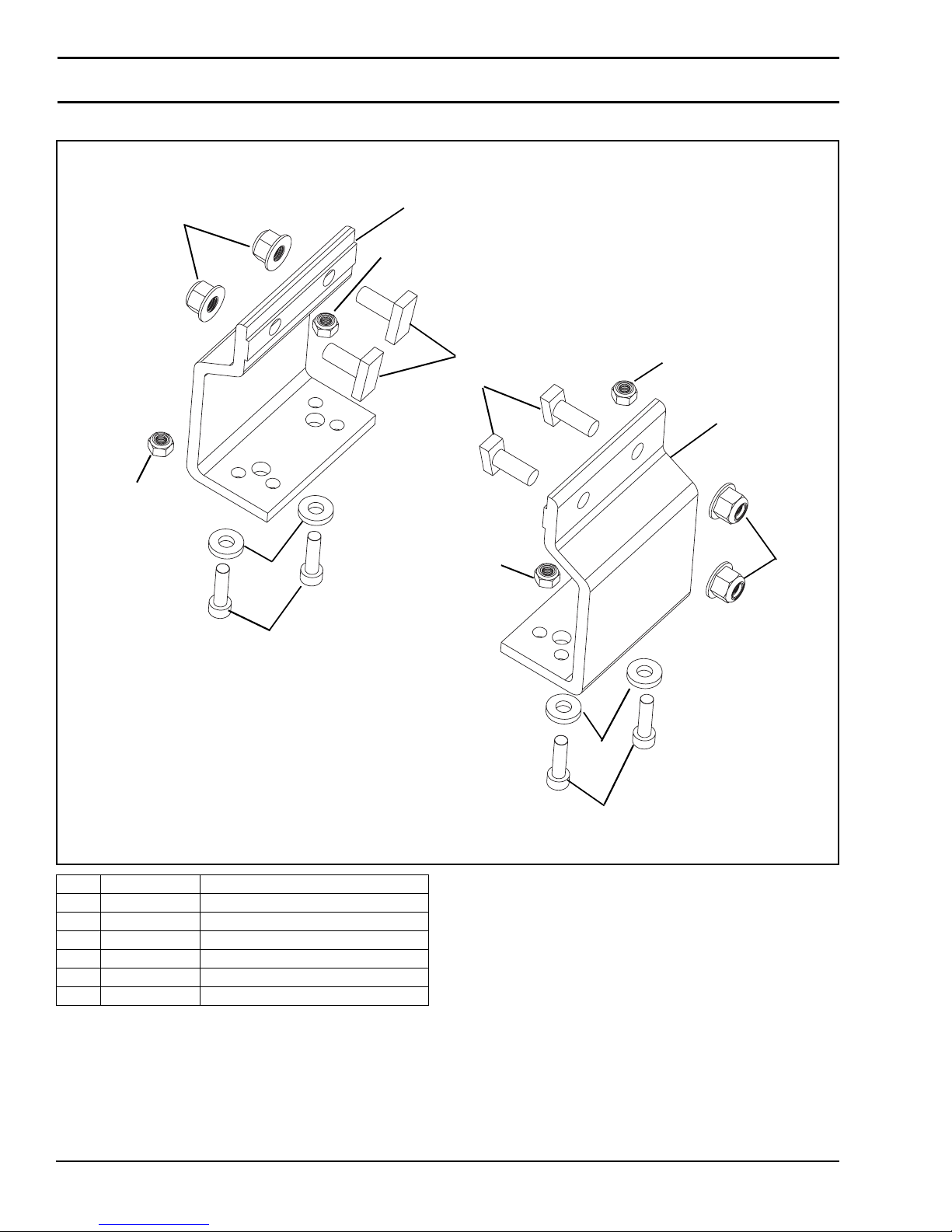
Service Parts
Mounting Brackets
6
5
3
4
2
5
1
1
5
5
2
6
Item Part Number Description
1 834-007 Stud, M8 x 20 mm
2 834-008 Mounting Bracket
3 605279P Washer
4 920622M Socket Head Screw, M6-1.00 x 22 mm
5 990602M Hex Nut, M6-1.00
6 990812M Flanged Hex Nut, M8-1.25
Dorner Mfg. Corp. 70 851-757 Rev. A
3
4
2200 Series SmartFlex Conveyors
Page 71
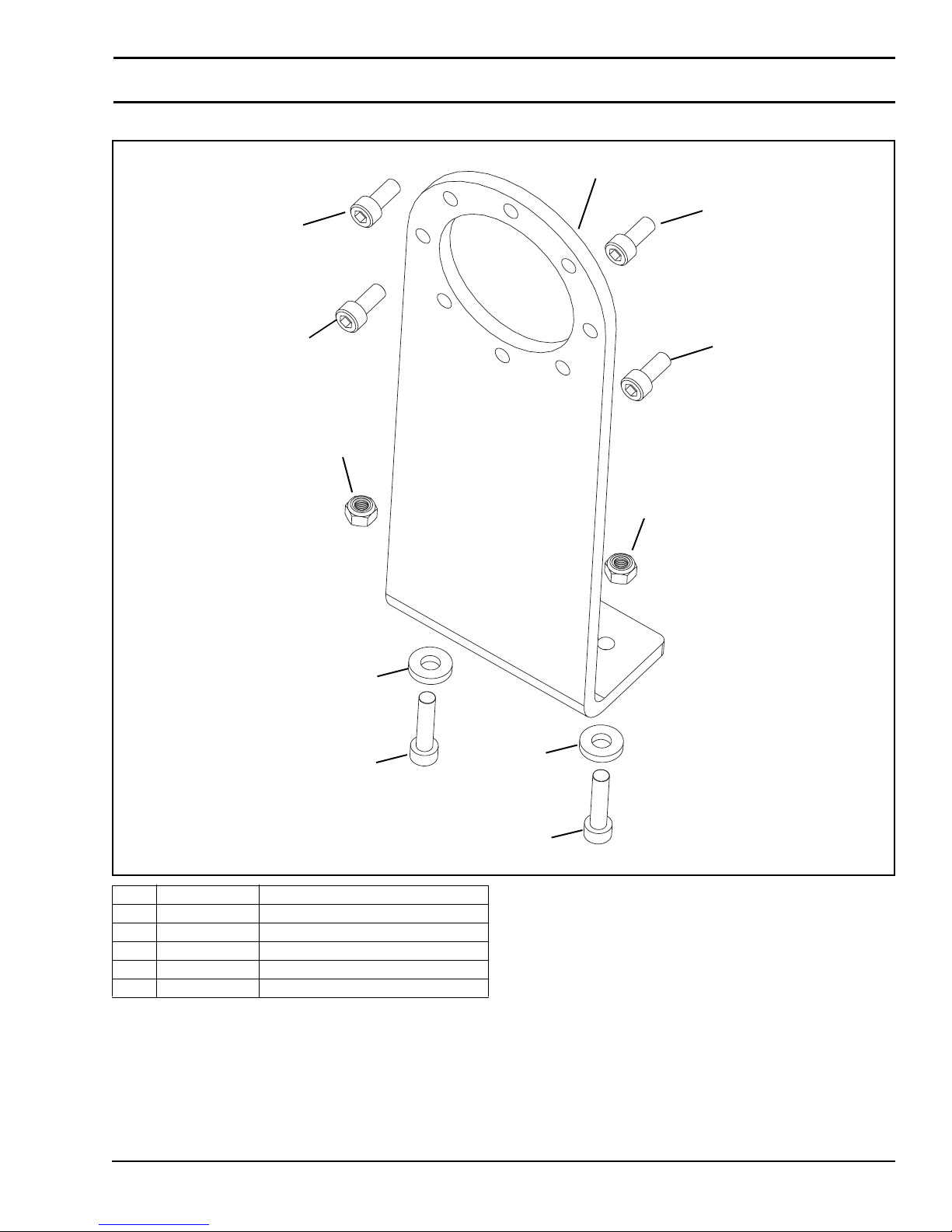
Motor Mounting Assembly
3
Service Parts
1
3
3
5
5
2
4
2
3
Item Part Number Description
1 203166 Motor Mounting Bracket
2 605279P Washer
3 920614M Socket Head Screw, M6-1.00 x 14 mm
4 920625M Socket Head Screw, M6-1.00 x 25 mm
5 990602M Hex Nut, M6-1.00
851-757 Rev. A 71 Dorner Mfg. Corp.
4
2200 Series SmartFlex Conveyors
Page 72
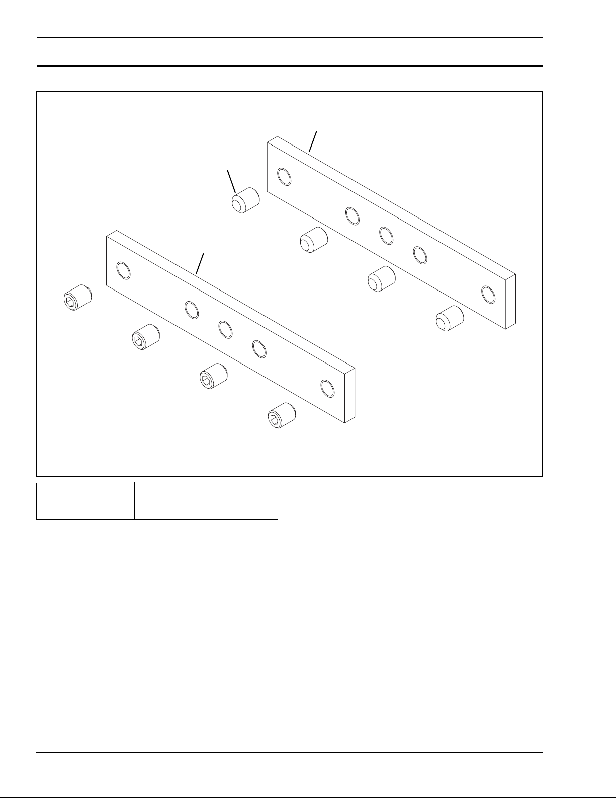
Service Parts
Connecting Assembly
1
2
1
Item Part Number Description
1 834-005 Connecting Bracket
2 970810M Set Screw, M8-1.25 x 10 mm
Dorner Mfg. Corp. 72 851-757 Rev. A
2200 Series SmartFlex Conveyors
Page 73
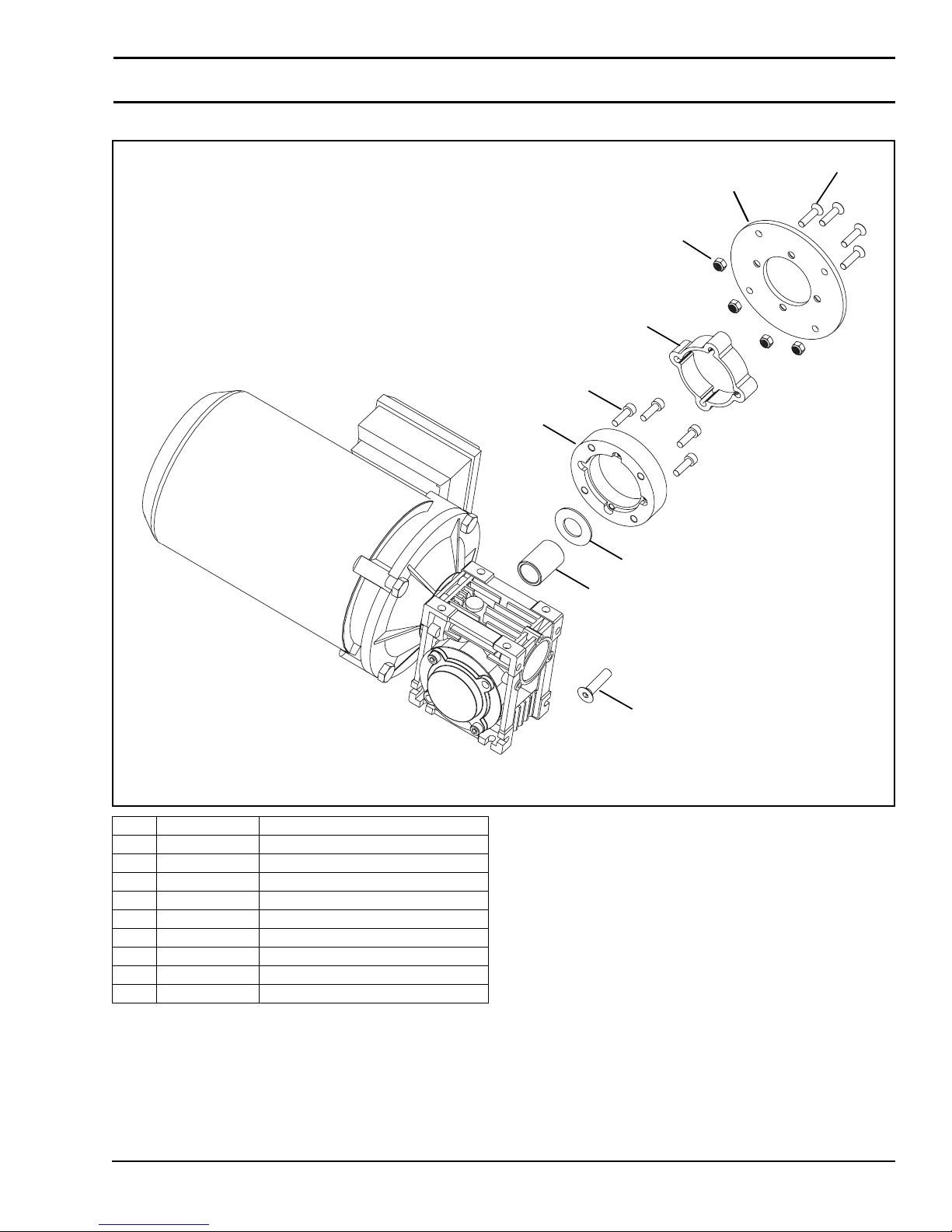
Gearmotor Mounting Package
Service Parts
7
3
8
2
6
5
Item Part Number Description
1 807-2277 Spring Disc
2 202270-00075 Extrusion
3 202971 Drive Plate
4 203065 Drive Spacer
5 350115 Adapter Ring
6 920620M Socket Head Screw, M6-1.00 x 20 mm
7 930625M Flat Head Screw, M6-1.00 x 25 mm
8 990602M Hex Nut, M6-1.00
9 931025M Flat Head Screw, M10-1.50 x 25 mm
1
4
9
851-757 Rev. A 73 Dorner Mfg. Corp.
2200 Series SmartFlex Conveyors
Page 74
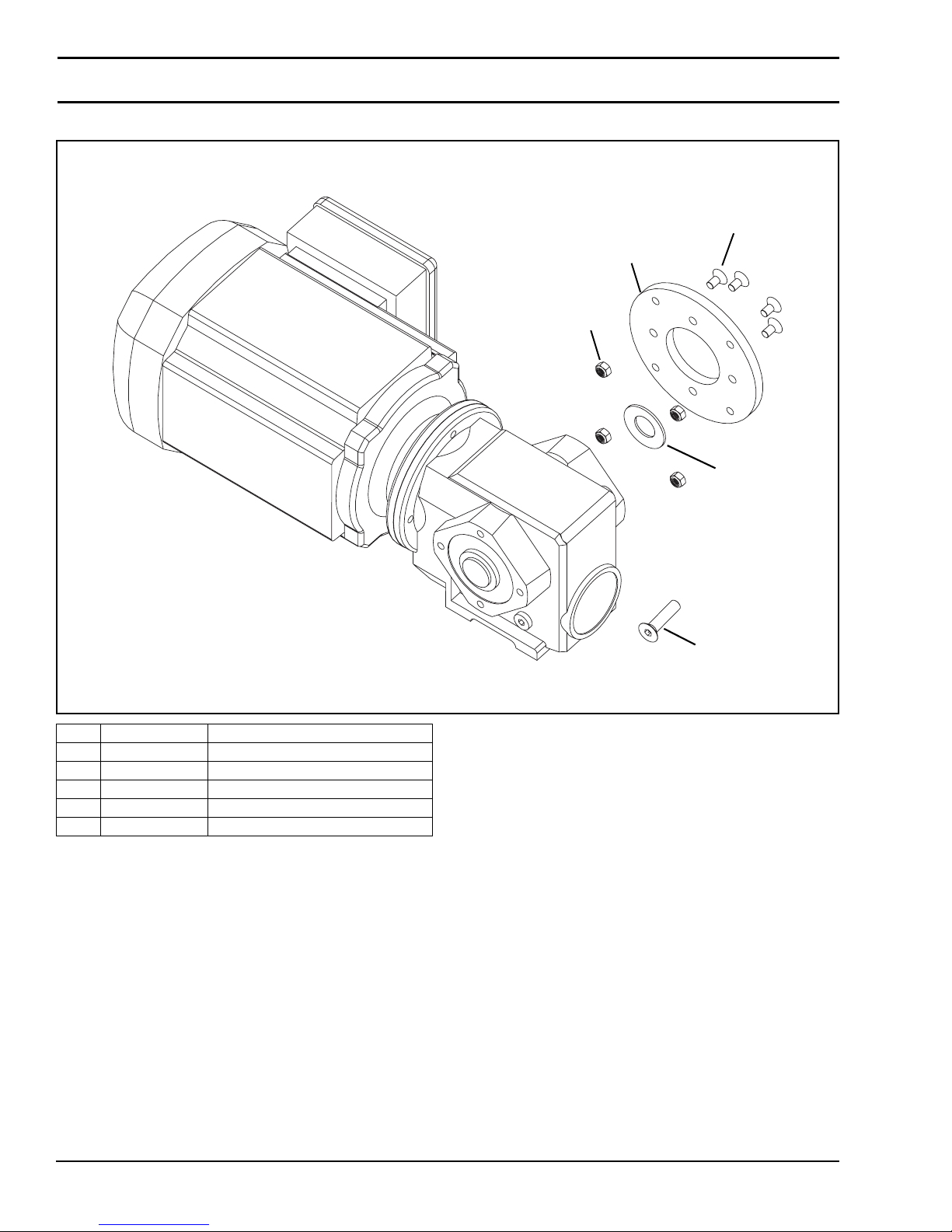
Service Parts
SEW Gearmotor Mounting Package
3
2
4
1
Item Part Number Description
1 807-2277 Spring Disc
2 203043 Drive Plate
3 930612M Flat Head Screw, M6-1.00 x 12 mm
4 990602M Hex Nut, M6-1.00
5 931025M Flat Head Screw, M10-1.50 x 25 mm
5
Dorner Mfg. Corp. 74 851-757 Rev. A
2200 Series SmartFlex Conveyors
Page 75
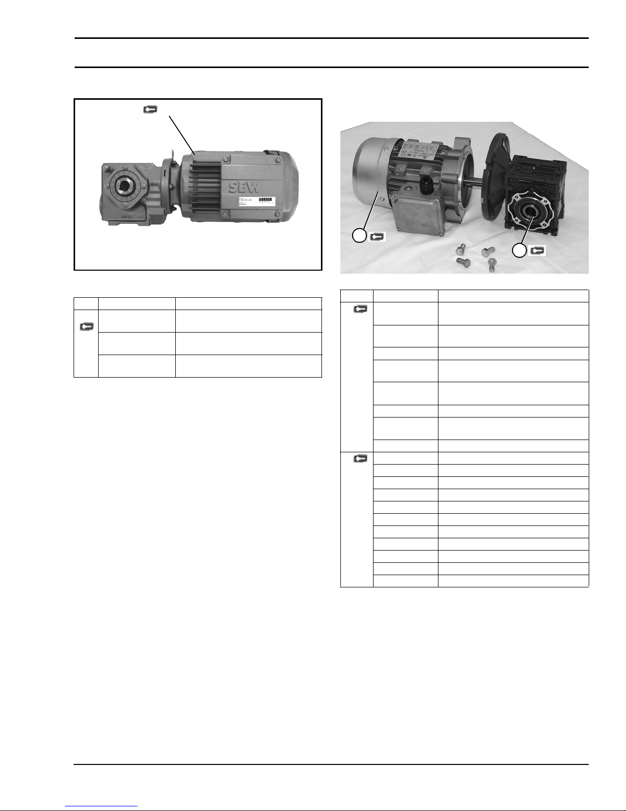
Service Parts
90° SEW Gearmotors 90° Industrial Gearmotors
1
Item Part Number Description
1 32M038WS423EN Gear motor, 0.80 Hp (0.37 Kw),
230/460 Volts, 37.7:1
32M013WS423EN Gearmotor, 0.75 Hp (0.56 Kw),
230/460 Volts, 13.4:1
32M007WS423EN Gearmotor, 1.00 Hp (0.75 Kw),
230/460 Volts, 6.8:1
U.S. Version
1
2
Item Part No. Description
1 62MES411FN Motor, 0.25hp (0.19Kw), 115/230 Volts,
60 Hz, 1-Phase
62MES423FN Motor, 0.25hp (0.19Kw), 208-230/460
Volts, 60 Hz, 3-Phase
22MSD3DEN Motor, 0.25hp (0.19Kw), 130 VDC
62MEH411FN Motor, 0.5hp (0.37Kw), 115/230 Volts,
60Hz, 1-Phase
32MES423FN Motor, 0.5hp (0.37Kw) 208-230/460
Volts, 60Hz, 3 Phase
62MHD9DEN Motor, 0.5hp (0.37Kw), 90 VDC
32MES423EN Motor, 0.5hp (0.37Kw), 230 Volts, 3
Phase Inver ter Duty
32MHD9DEN Motor, 0.75 hp, (0.56Kw), 90 VDC
2 32M005EL Gear Reducer, 5:1, NEMA 42CZ
32M010EL Gear Reducer, 10:1, NEMA 42CZ
32M020EL Gear Reducer, 20:1, NEMA 42CZ
32M040EL Gear Reducer, 40:1, NEMA 42CZ
32M060EL Gear Reducer, 60:1, NEMA 42CZ
32M005ES Gear Reducer, 5:1, NEMA 56C
32M010ES Gear Reducer, 10:1, NEMA 56C
32M020ES Gear Reducer, 20:1, NEMA 56C
32M040ES Gear Reducer, 40:1, NEMA 56C
32M060ES Gear Reducer, 60:1, NEMA 56C
32M010EH Gear Reducer, 10:1, NEMA 140 TC
851-757 Rev. A 75 Dorner Mfg. Corp.
2200 Series SmartFlex Conveyors
Page 76
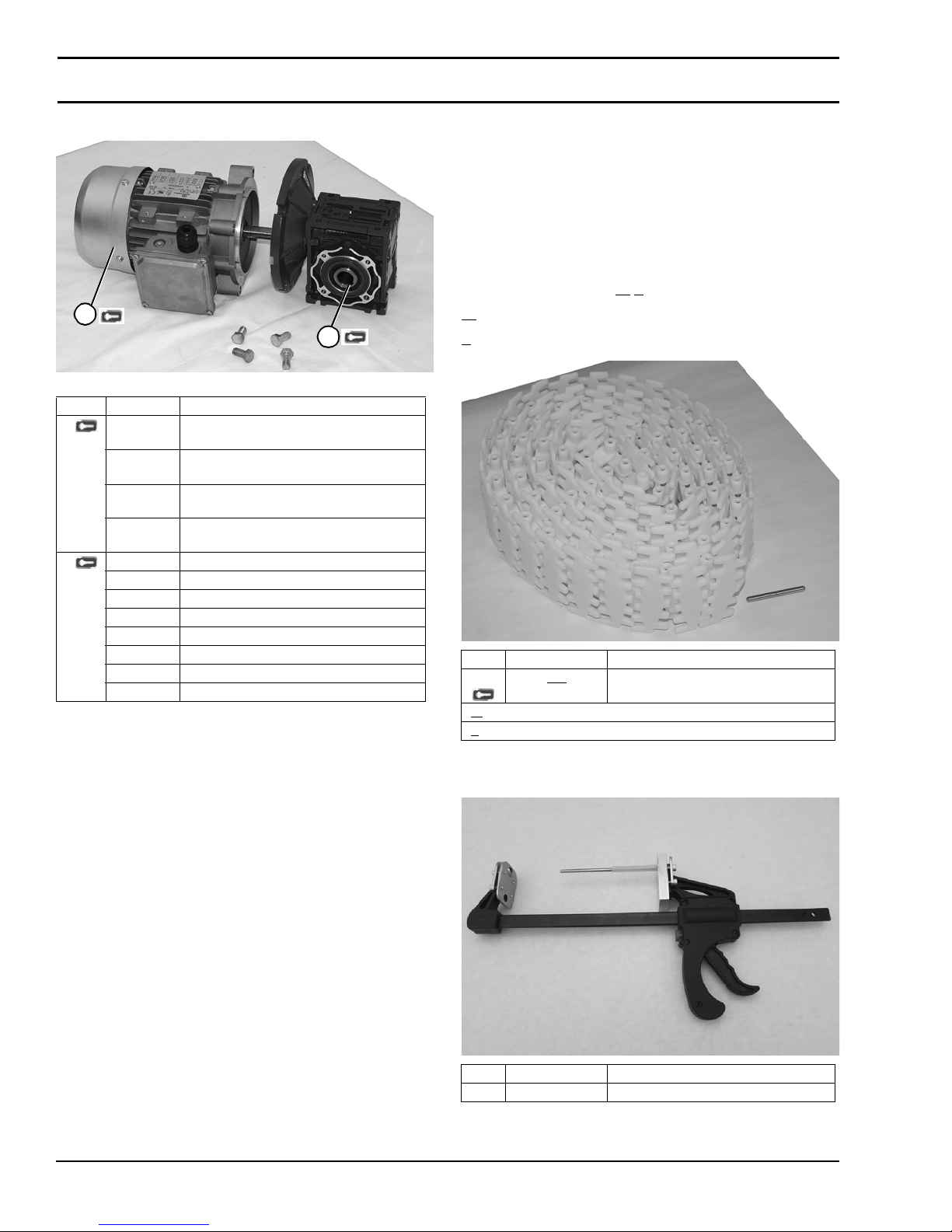
Service Parts
CE Version
1
2
Item Part No. Description
1 826-281 Motor, 0.19 kW 230 Volts, 1400 RPM
50 Hz, 1-Phase
826-282 Motor, 0.37 kW 230 Volts, 1400 RPM
50 Hz, 1-Phase
826-284 Motor, 0.19 kW 230/400 Volts, 1400 RPM
50 Hz, 3-Phase
826-285 Motor, 0.37 kW 230/400 Volts, 1400 RPM
50 Hz, 3-Phase
2 62Z005ES Gear Reducer, 5:1, 63 B5
62Z010ES Gear Reducer, 10:1, 63 B5
62Z020ES Gear Reducer, 20:1, 63 B5
62Z040ES Gear Reducer, 40:1, 63 B5
62Z060ES Gear Reducer, 60:1, 63 B5
32Z005ES Gear Reducer, 5:1, 71 B5
32Z010ES Gear Reducer, 10:1, 71 B5
32Z020ES Gear Reducer, 20:1, 71 B5
Ordering a Replacement Chain
Determine the length of the chain required for the conveyor
and round up to the next foot length. Order the proper
number of chain re pair kits (1' long each) for your conveyor.
Dorner will ship ch ain kit s that are of reas onable length ful ly
assembled.
Example:
Overall chain length = 42' 5" (round up to 43')
Order Qty (43) of 834-0 W
W = Width (2=65, 3=105 & 4=150 width conveyors)
= Chain type (2=Low Friction, 3=Friction Insert Chains)
T
Item Part Number Description
1834-0WT
= Width (2=65, 3=105 & 4=150 width conveyors)
W
= Chain type (2=Low Friction, 3=Friction Inser t Chains)
T
T
Chain Repair Kit (Includes 1 ft (305
mm) of chain and assembly pins)
Dorner Mfg. Corp. 76 851-757 Rev. A
Belt Removal Tool
Item Part Number Description
1 203480 Belt Removal Tool
2200 Series SmartFlex Conveyors
Page 77

Notes
851-757 Rev. A 77 Dorner Mfg. Corp.
2200 Series SmartFlex Conveyors
Page 78
Return Policy
Returns must have prior written factory authorization or they will not be accepted. Items that are returned to Dorner without
authorization will not be credited nor returned to the original sender. When calling for authorization, please have the following
information ready for the Dorner factory representative or your local distributor:
1. Name and address of customer.
2. Dorner part number(s) of item(s) being returned.
3. Reason for return.
4. Customer's original order number used when ordering the item(s).
5. Dorner or distributor invoice number (if available, part serial number).
A representative will discuss action to be taken on the returned items and provide a Returned Goods Authorization (RMA)
number for reference. RMA will automatically close 30 days after being issued. To get credit, items must be new and
undamaged. There will be a return charge on all items returned for credit, where Dorner was not at fault. It is the customer’s
responsibility to prevent damage during return shipping. Damaged or modified items will not be accepted. The customer is
responsible for return freight.
Product Type
Standard Products Engineered to
Product Line Conveyors Gearmotors
1100
2200
2200 Modular Belt
2200 Precision Move
2300
2300 Modular Belt
3200
3200 LPZ
3200 Precision Move
4100
5200
5300
6200
Controls
7200 / 7300 50% return fee for all products
7350
7360
7400
7600
& Mounting
Packages
50% return fee for conveyors with modular belt,
Support
Stands
30% return fee for all products except:
cleated belt or specialty belts
Access ories Spare Part s
(non-belt)
non-returnable
Spare Belts
- Standard
Flat Fabric
Spare Belts -
Cleated &
Specialty
Fabr ic
Spare Belts Plastic Chain All equipment
non-returnable case-by-case
order parts
and parts
Returns will not be accepted after 60 days from original invoice date. The return charge covers inspection, cleaning,
disassembly, disposal and reissuing of components to inventory. If a replacement is needed prior to evaluation of returned item,
a purchase order must be issued. Credit (if any) is issued only after return and evaluation is complete.
Dorner has representatives throughout the world. Contact Dorner for the name of your local representative. Our Customer
Service Team will gladly help with your questions on Dorner products.
For a copy of Dorner's Warranty, contact factory, distributor, service center or visit our website at www.dorner.com.
For replacement parts, contact an authorized Dorner Service Center or the factory.
Dorner Mfg. Corp. reserves the right to change
or discontinue products without notice. All
products and services are covered in
accordance with our standard warranty. All
rights reserved. © Dorner Mfg. Corp. 2013
851-757 Rev. A Printed in U.S.A.
DORNER MFG. CORP.
975 Cottonwood Ave., PO Box 20
Hartland, WI 53029-0020 USA
TEL 1-800-397-8664 (USA)
FAX 1-800-369-2440 (USA)
Internet: www.dorner.com
Outside the USA:
TEL 1-262-367-7600
FAX 1-262-367-5827
 Loading...