

Page 1
851-299 Rev. C
Set-up, Operation
& Maintenance Manual
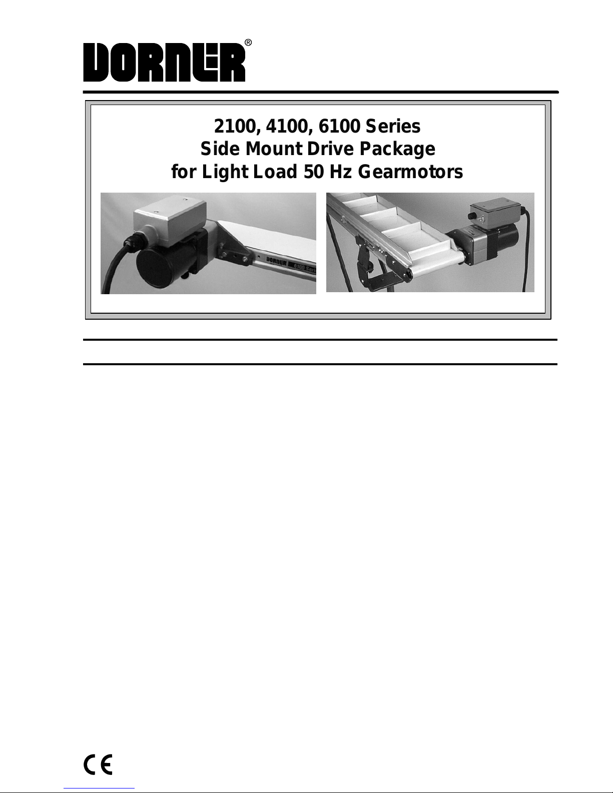
2100, 4100, 6100 Series
Side Mount Drive Package
for Light Load 50 Hz Gearmotors
Table of Contents
Warnings – General Safety 2. . . . . . . . . . . . . . . . . . . .
Introduction 2. . . . . . . . . . . . . . . . . . . . . . . . . . . . . . . .
Product Description 3. . . . . . . . . . . . . . . . . . . . . . . . . .
Specifications 3. . . . . . . . . . . . . . . . . . . . . . . . . . . . . . .
Installation 4. . . . . . . . . . . . . . . . . . . . . . . . . . . . . . . . .
Required Tools 4. . . . . . . . . . . . . . . . . . . . . . . . . . . .
Mounting 4. . . . . . . . . . . . . . . . . . . . . . . . . . . . . . . .
Preventative Maintenance & Adjustment 6. . . . . . . . .
Required Tools 6. . . . . . . . . . . . . . . . . . . . . . . . . . . .
Timing Belt Tensioning 6. . . . . . . . . . . . . . . . . . . . .
Timing Belt Replacement 6. . . . . . . . . . . . . . . . . . .
Drive or Driven Pulley Replacement 6. . . . . . . . . . .
Gearmotor Replacement 7. . . . . . . . . . . . . . . . . . . .
Service Parts 9. . . . . . . . . . . . . . . . . . . . . . . . . . . . . . .
Return Policy 10. . . . . . . . . . . . . . . . . . . . . . . . . . . . . .
Page 2
2100, 4100, 6100 Series Side Mount Drive Package for Light Load 50 Hz Gearmotors SOMM
851-299 Rev. C 2 Dorner Mfg. Corp.
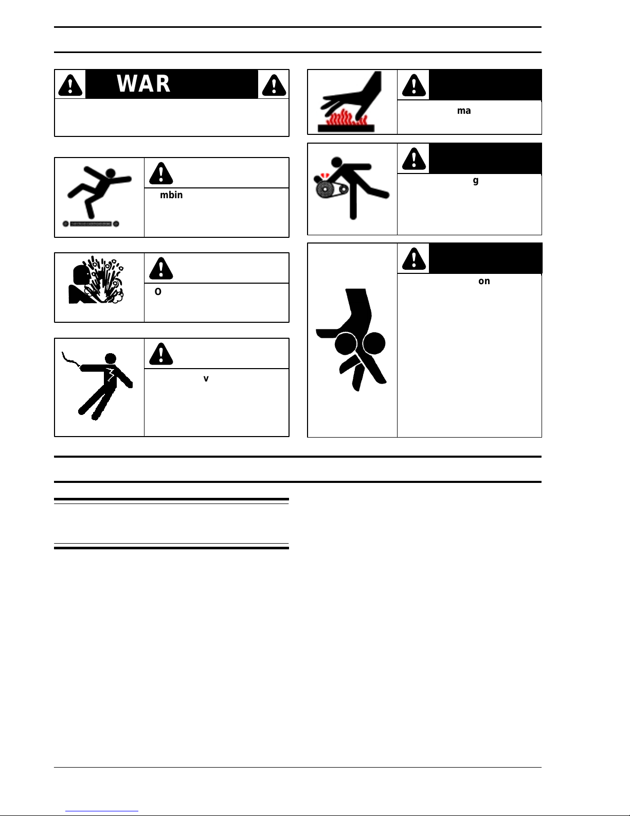
The safety alert symbol, black triangle with white
exclamation, is used to alert you to potential
personal injury hazards.
WARNING
Climbing, sitting, walking or
riding on conveyor will
cause severe injury.
KEEP OFF CONVEYORS.
DANGER
DANGER
DO NOT OPERATE
CONVEYORS IN AN
EXPLOSIVE ENVIRONMENT.
Hazardous voltage will
cause severe injury or
death.
LOCKOUT POWER BEFORE
WIRING.
DANGER
Gearmotors may be HOT.
DO NOT TOUCH Gearmotors.
WARNING
Exposed moving parts can
cause severe injury.
LOCK OUT POWER before
removing guards or
performing maintenance.
WARNING
Dorner cannot control the
physical installation and
application of conveyors.
Taking protective measures
is the responsibility of the
user.
When conveyors are used in
conjunction with other equipment or as part of a multiple
conveyor system, CHECK
FOR POTENTIAL PINCH
POINTS and other mechanical hazards before system
start-up.
WARNING
Introduction
IMPORTANT: Some illustrations may show
guards removed. Do NOT operate equipment without guards.
Upon receipt of shipment:
D Compare shipment with packing slip. Contact factory
regarding discrepancies.
D Inspect packages for shipping damage. Contact carrier
regarding damage.
D Accessories may be shipped loose. See accessory in-
structions for installation.
Dorner 2100 Series conveyors are covered by the
following patent numbers: 5131529, 5174435, and
corresponding patents and patent applications in other
countries.
Dorner 4100 Series conveyors are covered by patent
number 3923148 and c orresponding patents a nd patent
applications in other countries.
Dorner 6100 Series conveyors are covered by patent
number 5174435 and c orresponding patents a nd patent
applications in other countries.
Dorner’s Limited Warranty applies.
Dorner reserves the right to make changes at any time
without notice or obligation.
Warnings – General Safety
Page 3
2100, 4100, 6100 Series Side Mount Drive Package for Light Load 50 Hz Gearmotors SOMM
Dorner Mfg. Corp. 3 851-299 Rev. C
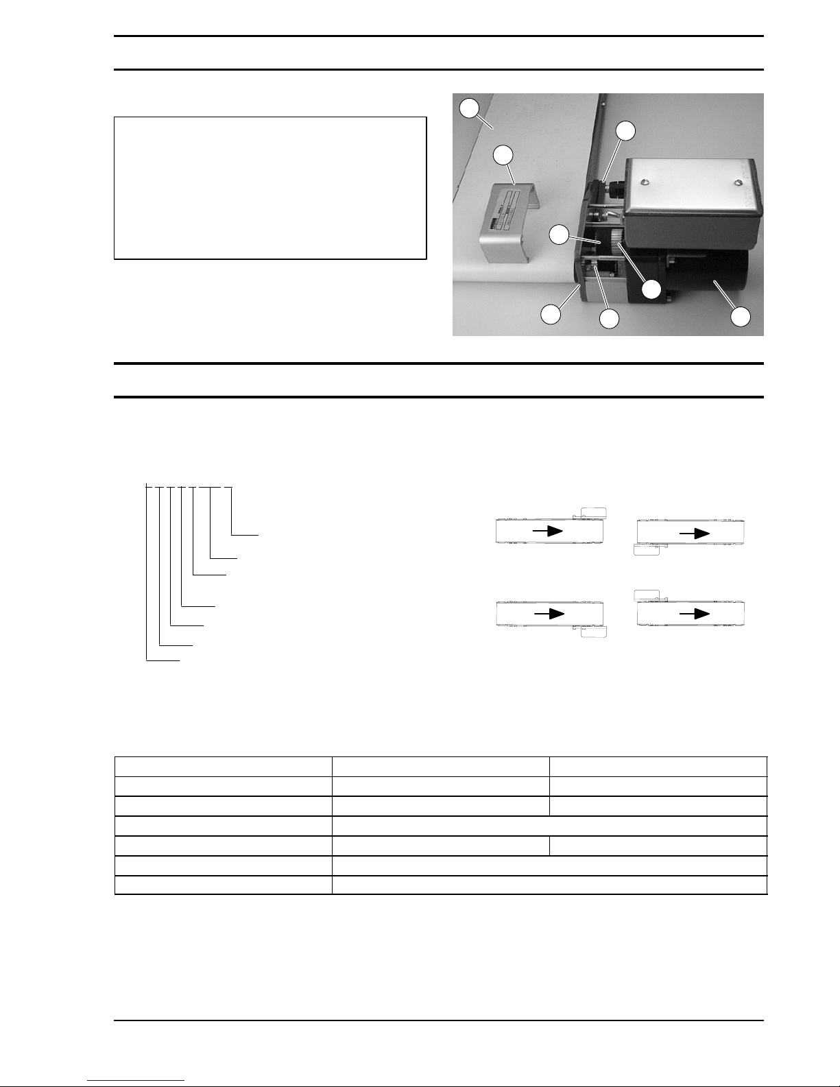
Refer to Figure 1 for typical components.
A Conveyor
B Mounting Bracket
C Gearmotor
D Belt Tensioner
E Cover
F Timing Belt
G Drive Pulley
H Driven Pulley
Typical Components
Figure 1
G
B
F
D
C
H
E
A
Specifications
Gearmotor Mounting Package Models:
Example:
Language Code = CE English
Output Shaft Type = Parallel Shaft
Gearmotor Type = Light Load,
Industrial,
Fixed Speed
Mount Style = Side Mount
Conveyor Width Reference*
Mount Position = A, B, C or D
(see detail to the right)
D
C
BA
2 U S P L WW A
2 = 2100 Series Conveyor
4 = 4100 Series Conveyor
6 = 6100 Series Conveyor
* See “Ordering and Specifications” Catalog for details.
Table 1: Gearmotor Specifications
Single Phase Three Phase
Output Power 0.022 kw 0.02 kw
Input Voltage 230 Volts A.C. 230/400 Volts A.C.
Input Frequency 50 Hz
Full Load Amperes 0.31 Amperes 0.22/0.13 Amperes
Gearmotor Ratios 8:1 and 28.1:1
Protection Ratings IP44
Product Description
Page 4
2100, 4100, 6100 Series Side Mount Drive Package for Light Load 50 Hz Gearmotors SOMM
851-299 Rev. C 4 Dorner Mfg. Corp.
Table 2: Belt Speeds for Light Load Fixed Speed Parallel Shaft 50 Hz Gearmotors
Gearmotors
Belt
Speed
Part Number RPM N-m
M/min
62U028PL4(vp)FN 41 2.6 4
62U008PL4(vp)FN 144 0.9 13
(vp) = voltage and phase
21 = 230 V, 1-phase
23 = 230 V, 3-phase
43 = 400 V, 3-phase
NOTE: 203 through 610 mm wide conveyors with
light
load drives should be limited to 2438 mm length.
NOTE: For belt speed other than those listed, con-
tact factory for details.
Installation
Required Tools
D Hex key wrenches:
2 mm, 3 mm, 5 mm
D Torque wrench
Mounting
Exposed moving parts can
cause severe injury.
LOCK OUT POWER before
removing guards or
performing maintenance.
WARNING
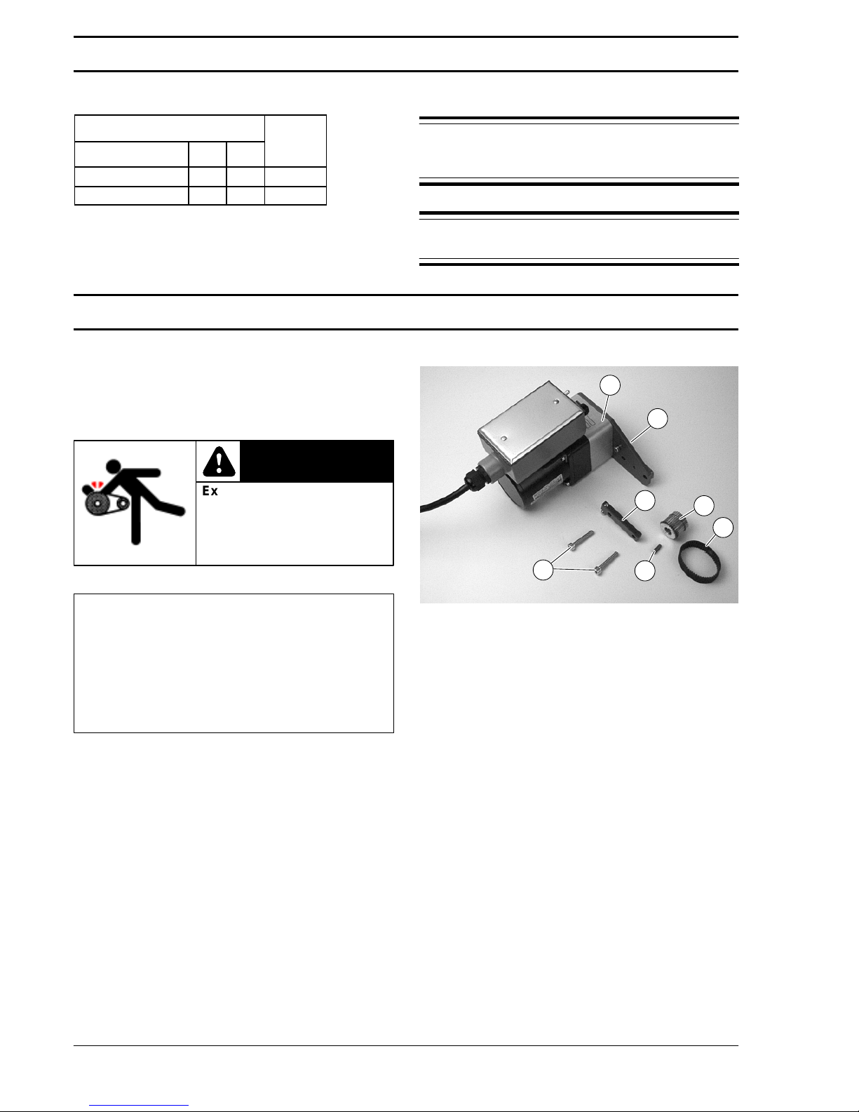
Installation Component List
I Side Mount Assembly
J Driven Pulley
K Top Cover
L Tensioner Bar
M Timing Belt
N Key
O M6 Socket Head Screws (2x)
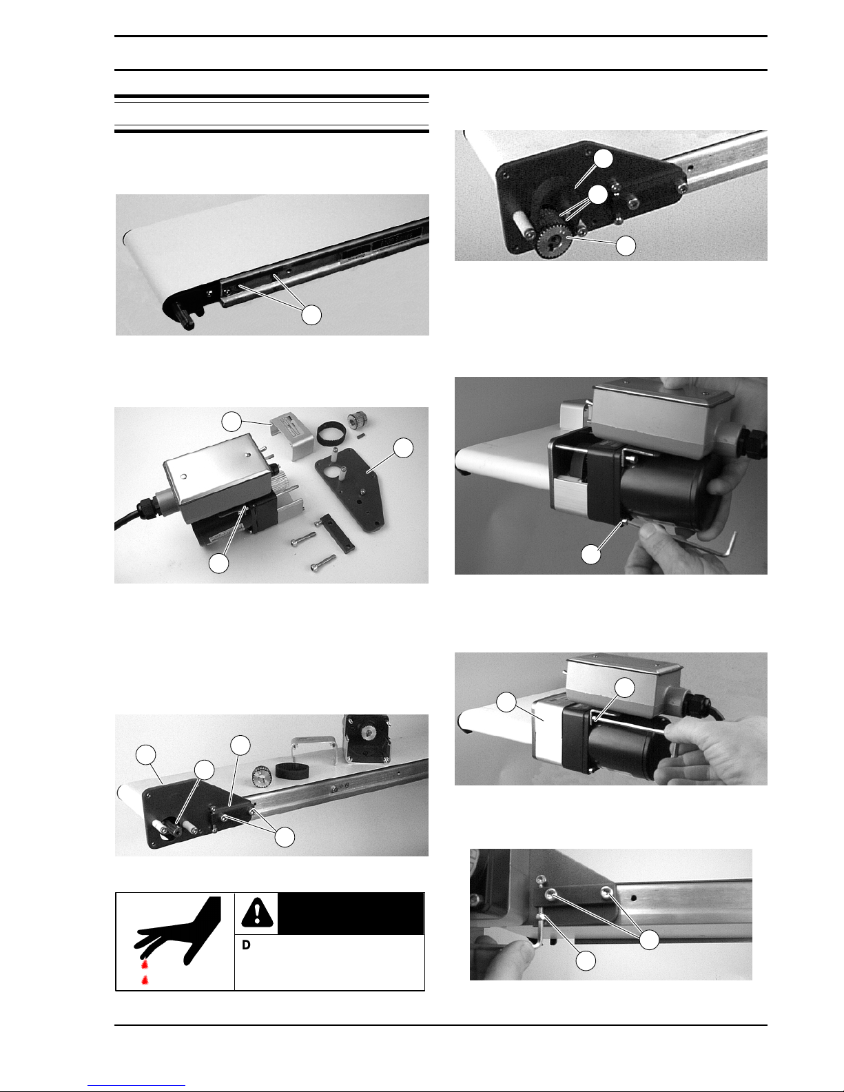
1. Typical components (Figure 2)
Figure 2
K
I
J
M
L
N
O
Specifications
Page 5
2100, 4100, 6100 Series Side Mount Drive Package for Light Load 50 Hz Gearmotors SOMM
Dorner Mfg. Corp. 5 851-299 Rev. C
NOTE: 6100 conveyor shown, 2100 & 4100 similar.
2. Locate drive output shaft and remove two (2) screws
(P of Figure 3).
Figure 3
P
3. Loosen four (4) screws (Q of Figure 4). Detach
mounting bracket (R).
Figure 4
K
Q
R
4. Remove two (2) top screws (Q) and remove top
cover (K).
5. Attach mounting bracket (R of Figure 5) and
tensioner bar (L) with screws (O). Hand-tighten
screws (O).
Figure 5
N
R
L
O
Drive shaft keyway may be
sharp.
HANDLE WITH CARE.
WARNING
6. Install key (N of Figure 5).
7. Install driven pulley (J of Figure 6). Tighten two (2)
set screws to 3.7 Nm.
Figure 6
M
S
J
8. Place timing belt (M of Figure 6) over driven pulley
(J) and between belt flanges (S).
9. Insert gearmotor drive pulley into timing belt.
Mount assembly with two (2) bottom screws (Q of
Figure 7). Tighten to 5 Nm.
Figure 7
Q
10. Insert top cover (K of Figure 8) into bottom cover.
Attach top cover with two (2) top screws (Q).
Tighten to 5 Nm.
Figure 8
Q
K
11. Tighten timing belt tensioner screw (T of Figure 9)
to 1.7 Nm.
Figure 9
T
O
12. Tighten screws (O) to 9 Nm.
Installation
Page 6
2100, 4100, 6100 Series Side Mount Drive Package for Light Load 50 Hz Gearmotors SOMM
851-299 Rev. C 6 Dorner Mfg. Corp.
Required Tools
D Hex key wrenches
– 2 mm, 3 mm & 5 mm
D Torque wrench
Timing Belt Tensioning
Exposed moving parts can
cause severe injury.
LOCK OUT POWER before
removing guards or
performing maintenance.
WARNING
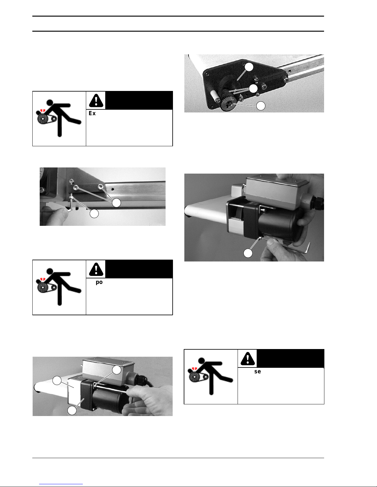
1. Loosen two (2) screws (O of Figure 10). Tighten
timing belt tensioner screw (T) to 1.7 Nm.
Figure 10
T
O
2. Tighten screws (O) to 9 Nm.
Timing Belt Replacement
Exposed moving parts can
cause severe injury.
LOCK OUT POWER before
removing guards or
performing maintenance.
WARNING
1. Loosen two (2) screws (O of Figure 10).
2. Loosen timing belt tensioner screw (T).
3. Remove four (4) screws (Q of Figure 11). Remove
gearmotor (U) and top cover (K).
Figure 11
Q
K
U
4. Remove old timing belt (M of Figure 12).
Figure 12
M
J
S
5. Place new timing belt (M) over driven pulley (J) and
between belt flanges (S).
6. Insert gearmotor drive pulley into timing belt.
Mount assembly with two (2) bottom screws (Q of
Figure 7). Tighten to 5 Nm.
Figure 13
Q
7. Insert top cover (K of Figure 11) into bottom cover.
Mount assembly with two (2) top screws (Q).
Tighten to 5 Nm.
8. Tighten timing belt tensioner screw (T of Figure 10)
to 1.7 Nm.
9. Tighten screws (O) to 9 Nm.
Drive or Driven Pulley Replacement
Exposed moving parts can
cause severe injury.
LOCK OUT POWER before
removing guards or
performing maintenance.
WARNING
1. Complete steps 1 through 4 of “Timing Belt
Replacement” section on this page.
Preventive Maintenance and Adjustment
Page 7
2100, 4100, 6100 Series Side Mount Drive Package for Light Load 50 Hz Gearmotors SOMM
Dorner Mfg. Corp. 7 851-299 Rev. C
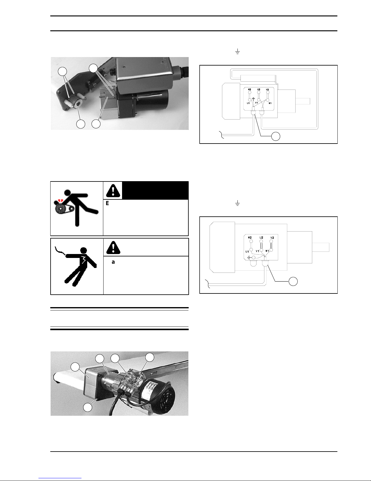
2. Loosen set screws (V of Figure 14) and remove driven
pulley (J) or drive pulley (W).
Figure 14
V
V
W
J
3. Replace drive or driven pulley. Tighten set screws
to 3.7 Nm.
4. Complete steps 5 through 9 of “Timing Belt
Replacement” section on page 6.
Gearmotor Replacement
Exposed moving parts can
cause severe injury.
LOCK OUT POWER before
removing guards or
performing maintenance.
WARNING
Hazardous voltage will
cause severe injury or
death.
LOCKOUT POWER BEFORE
before wiring.
DANGER
1. For single phase motor:
NOTE: Single phase gearmotor shown, three phase
similar.
a. Loosen terminal box screws (X of Figure 15) and
remove cover (Y).
Figure 15
X
Y
Q
U
K
b. Record wire colors on terminals U1, W1 and
ground (
) (Figure 16). Loosen terminals U1, W1
and ground and remove wires.
Figure 16
Z
c. Loosen cord grip (Z of Figure 16) and remove cord.
2. For three phase motor:
a. Loosen terminal box screws (X of Figure 15) and
remove cover (Y).
b. Record wire colors on terminals U1, V1, W1 and
ground (
) (Figure 17). Loosen terminals U1, V1,
W1 and ground and remove wires.
Figure 17
Z
c. Loosen cord grip (Z of Figure 17) and remove cord.
3. Remove four (4) screws (Q of Figure 15). Remove
gearmotor (U) and top cover (K).
Preventive Maintenance and Adjustment
Page 8
2100, 4100, 6100 Series Side Mount Drive Package for Light Load 50 Hz Gearmotors SOMM
851-299 Rev. C 8 Dorner Mfg. Corp.
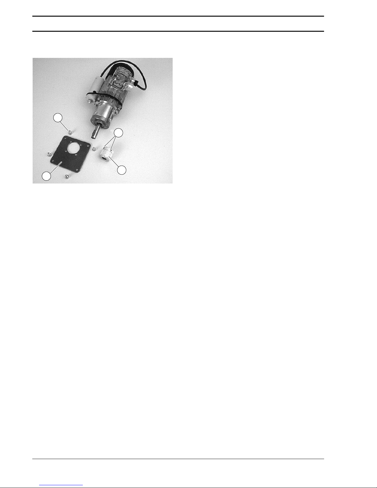
4. Loosen two (2) set screws (V of Figure 18). Remove
drive pulley (W).
Figure 18
W
V
AA
AB
5. Remove four (4) screws (AA) and detach adapter
plate (AB).
6. Mount adapter plate (AB) to new gearmotor with
four (4) screws (AA). Tighten to 5 Nm.
7. Replace drive pulley (W) and tighten set screws (V)
to 3.7 Nm.
8. Complete steps 5 through 9 of “Timing Belt
Replacement” section on page 6.
9. Replace wiring:
D For a single phase motor, reverse step 1 on page 7.
D For a three phase motor, reverse step 2 on page 7.
Preventive Maintenance and Adjustment
Page 9
2100, 4100, 6100 Series Side Mount Drive Package for Light Load 50 Hz Gearmotors SOMM
Dorner Mfg. Corp. 9 851-299 Rev. C
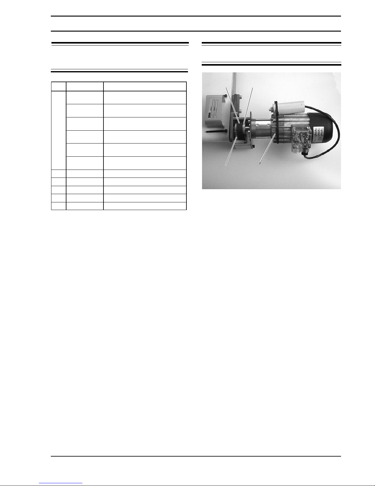
NOTE: For replacement parts other than those
shown on this page, contact an authorized Dorner
Service Center or the factory.
Item Part No. Part Description
1
62U028PL421
Gearmotor, 22 W, 230 Volts, 41 RPM,
50 Hz, 1-Phase. 28:1
62U008PL421
Gearmotor, 22 W, 230 Volts, 144 RPM,
50 Hz, 1-Phase, 8:1
62U028PL423
Gearmotor, 20 W, 230Volts, 41 RPM,
50 Hz, 3-Phase, 28:1
62U008PL423
Gearmotor, 20 W, 230 Volts, 144 RPM,
50 Hz, 3-Phase, 8:1
62U028PL443
Gearmotor, 20 W, 400 Volts, 41 RPM,
50 Hz, 3-Phase, 28:1
62U008PL443
Gearmotor, 20 W, 400 Volts, 144 RPM,
50 Hz, 3-Phase, 8:1
2 814-088 Timing Belt, 3mm x 15 mm
3 450077M Drive Pulley, 12 mm Bore
4 807-1070 Drive Pulley Woodruff Key
5 450077M Driven Pulley, 12 mm Bore
6 980422M Driven Pulley Key, 4 mm x 22 mm
NOTE: Single phase gearmotor shown, three phase
similar.
Figure 19
5,6
3,4
2
1
Service Parts
Page 10
No returns will be accepted without prior written factory authorization. When calling for authorization, please
have the following information ready for the Dorner Factory representative or your local distributor:
1. Name and address of customer.
2. Item(s) being returned.
3. Reason for return.
4. Customer’s original order number used when ordering the item(s).
5. Dorner or distributor invoice number.
A representative will discuss action to be taken on the Returned items and provide a Returned Goods
Authorization Number to reference.
There will be a 15% restocking charge on all new items returned for credit where Dorner was not at fault. These
will not be accepted after 60 days from original invoice date. The restocking charge covers inspection, cleaning,
disassembly, and reissuing to inventory.
If a replacement is needed prior to evaluation of returned item, a purchase order must be issued. Credit
(if any) is issued only after return and evaluation is complete.
Dorner has representatives throughout the world. Feel free to contact Dorner for the name of your local
representative. Our technical sales and service staff will gladly help with your questions on Dorner products.
For a copy of Dorner’s Limited Warranty, contact factory, distributor, service center or visit our website @
www.dorner.com
851-299 Rev. C Printed in U.S.A. 400
975 Cottonwood Ave. PO Box 20
Hartland, WI 53029-0020 USA
Dorner Mfg. Corp. reserves the right to change or
discontinue products without notice. All products and
services are covered in accordance with our standard
warranty. All rights reserved.
Dorner Mfg. Corp. 2000
DORNER
Arnold-Sommerfeld-Ring 2
D-52499 Baesweiler
USA
TEL 1-800-397-8664 (USA)
FAX 1-800-369-2440 (USA)
Germany
TEL (02401) 80 52 90
FAX (02401) 80 52 93
Internet: www.dorner.com
Outside the USA:
TEL 1-262-367-7600, FAX
1-262-367-5827
DORNER MFG. CORP.
Return Policy
 Loading...