


1
Thank you for purchasing and using the DORNA DLM1 series inverters. Please read the operation
manual carefully before putting the inverter to use so as to correctly install and operate the inverter
and ensure safety. Please keep the operation manual handy for future reference, maintenance,
inspection and repair.
The inverter must be installed, tested and commissoned by specialized personnels. The marks of
and other symbols in the manual remind you of the safety precautions
during the handling, installation, running and inspection. Please follow
these instructions to make sure the safe use of the inverter. In case of any doubt please contact our
local agent for consultation. Our professional persons are willing and ready to serve you.
The manual is subject to change without notice.
Danger indicates wrong use may kill or injure people.
!Caution indicates wrong use may damage the inverter or mechanical system.
Danger
!Caution

2
Danger
● Be sure to turn off the input power supply before wiring.
● Do not touch any internal electrical circuit or component when the charging lamp is still on
after the AC power supply is disconnected, which means the inverter still has high voltage inside and
it is very dangerous.
● Do not check components and signals on the circuit boards during operations.
● Do not dissemble or modify any internal connecting cord, wiring or component of the inverter
by yourself.
● Be sure to make correct grounding connection of the earth terminal of the inverter.
● Never remodel or replace control boards and components by yourself. It may expose you to an
electrical shock or explosion, etc.
! Caution
● Do not make any voltage-withstanding test with any component inside the inverter. These
semi-conductor parts are subject to the damage of high voltage.
● Never connect the AC main circuit power supply to the output terminals U.V W of the inverter.
●The main electric circuit boards of CMOS and IC of the inverter are subject to the effect and
damage of static electricity. Don’ t touch the main circuit boards.
● Installation, testing and maintenance must be performed by qualifed professional personnel.
● The inverter should be discarded as industrial waste. It is forbidden to burn it

3
Contents
Ⅰ.Safety Precautions ............................................................................................................................ 4
1.1 Introduction ........................................................................................................................... 4
1.2 Before Power-up .................................................................................................................... 4
1.3 During Power-up ................................................................................................................... 6
1.4 JOG operation ....................................................................................................................... 6
1.5 During Operation .................................................................................................................. 6
Ⅱ Product Introduction and installation .............................................................................................. 8
2.1 DLM1 Series model description ........................................................................................... 8
2.2 Particular Specifcations ........................................................................................................ 9
2.3 General Specifications .......................................................................................................... 9
2.4 Storage and Installation ..................................................................................................... 11
2.5 Installation Site and Environment ..................................................................................... 11
2.6 Installation and Direction ................................................................................................... 12
Ⅲ Wiring ........................................................................................................................................... 13
3.1 Main Circuit Wiring Schematic Diagram ......................................................................... 13
3.2 Descriptions of Terminal Blocks ........................................................................................ 14
3.3 Basic Connection Diagram ................................................................................................. 15
3.4 Precautions on Wiring ........................................................................................................ 16
3.5 Optional parts...................................................................................................................... 18
Ⅳ Maintenance and Troubleshooting ................................................................................................ 19
4.1 Maintenance check Notes ................................................................................................... 19
4.2 Regular inspection program ............................................................................................... 19
4.3 Fault information and troubleshooting ............................................................................. 20
Ⅴ Instruction of the Digital Operator ................................................................................................ 23
5.1 Description of the Digital Operator ................................................................................... 23
5.2 Description of Indicator Lamp Status ............................................................................... 23
5.3 Operation Examples ........................................................................................................... 24
Ⅵ Parameter Overview...................................................................................................................... 25
Appendix 1: Function List .................................................................................................................. 53
Appendix 2: Installation Dimensions .................................................................................................. 59
Appendix 3: MODBUS Communication Protocol ............................................................................. 60

4
Ⅰ.Safety Precautions
1.1 Introduction
The inverter has been strictly and well packed before ex-work. In consideration of various
factors during the transportation special attention should be paid to the following points before
the assembly and installation. If there is anything abnormal please notify the dealer or the
relevant people of our company.
● Check if the inverter has got any damage or deformation during the transportation and handling.
● Check if there is one piece of DLM1series inverter and one user manual when unpacking it.
●Check the information on the nameplate to see if the specifications meet your order (Operating
voltage and KVA value).
● Check if there is something wrong with the innerparts, wiring and circuit board.
● Check if each terminal is tightly locked and if there is any foreign article inside the inverter.
● Check if the operator buttons are all right.
1.2 Before Power-up
!Caution
Check to be sure that the voltage of the main circuit AC power supply matches the input
voltage of the inverter.
E terminals are grounding terminals. Be sure to make correct grounding connection of the
earth terminals of the motor and the inverter for safety.
No contactor should be installed between the power supply and the inverter to be used for
starting or stopping of the inverter. Otherwise it will affect the service life of the inverter.
Danger
●R(L),S,T(N) terminals are power input terminals, never mixed with U.V.W terminals. Be sure
that the wiring of the main circuit is correct. Otherwise it will cause damages of the inverter when
the power is applied to it.

5
! Caution
Do not carry the front cover of the inverter directly when handling. It should be handled with
the base to prevent the fall-off of the front cover and avoid the dropping of the inverter, which
may possibly cause the injuries to people and the damages to the inverter.
Mount the inverter on a metal or other noncombustible material to avoid the risk of fire.
Install the inverter in a safe location avoiding high temperature, direct sunlight, humid air or
water.
Keep the inverter from the reach of children or persons not concerned. The inverter can only
be used at the places accredited by our company. Any unauthorized working environment
may have the risks of fire, gas explosion, electric shock and other incidents.
Install a heat sink or other cooling device when installing more than one inverter in the same
enclosure so that the temperature inside the enclosure is kept below 40℃ to avoid overheat
or the risk of fre.
Be sure to turn off the power supply before dissembling or assembling the operation keypanel
and fxing the front cover to avoid bad contact causing faults or non-display of the operator.
● Do not install the inverter in a space with explosive gas to avoid the risk of explosion.
● If the inverter is used at or above 1000m above seal level, the cooling effciency will be
reduced, so please run it by de-rating.
Do not install any switch component like air circuit breaker or contactor at the output of the
inverter. If any of such components must be installed because of the requirements of process
and others, it must be ensured that the inverter has no output when the switch acts. In addition,
it is forbidden to install any capacitor for improvement of power factor or any varistor against
thunder at the output. Otherwise it will cause malfunctions, tripping protection and damages
of components of the inverter. Please remove them as shown in the below diagram.
It will affect the service life of the inverter.If a contact is connected to the front end of input
of the inverter to control its starts and stops. Generally it is required to control it through
Control terminals. Special attention should be paid to its use in the case of frequent starts and
stops.
● Please use an independent power supply for the inverter. Do avoid using the common
power supply with an electrical welder and other equipment with strong disturbance. Otherwise
it will cause the protection or even damage of the inverter.
U
Inverter V
W
M
KM
X
X

6
1.3 During Power-up
Danger
● Do not plug the connectors of the inverter during the power up to avoid any surge into the
main control board due to plugging, which might cause damage to the inverter.
● Always have the protective cover in place before power up to avoid electrical shock.
1.4 JOG operation
Procedures
Panel display after
operation
Pilot Lamp
Power-up
F000
FWD、STOP light
00.00
FWD、STOP light
05.00
FWD、STOP light
RUN
F05.0
FWD、RUN light and Fans
operation
STOP
F05.0
FWD、RUN light and Fans
operation
1.5 During Operation
Danger
● Never connect or disconnect the motor set while the inverter is in running. Otherwise it will
cause over-current trip and even burn up the main circuit of the inverter.
● Never remove the front cover of the inverter while the inverter is powered up to avoid any
injury of electric shock.
● Do not come close to the machine when the fault restart function is used to avoid anything
unexpected. The motor may automatically restart after its stop.
● The function of STOP Switch is only valid after setting, which is different with the use of
emergent stop switch. Please pay attention to it when using it.

7
!Caution
● Do not touch the heat braking resistor, or other heat elements. These can become very hot.
● Be sure that the motor and machine is within the applicable speed ranges before starting
operation because the inverter is quite easy to run from lower speed to higher speed.
● Do not check the signals on circuit boards while the inverter is running to avoid danger.
● Be careful when changing the inverter settings. The inverter has been adjusted and set before
ex-work. Do not adjust it wantonly. Please make proper adjustments according to the required
functions.
● Do consider the vibration, noise and the speed limit of the motor bearings and the mechanical
devices when the inverter is running at or above the frequency of 50Hz.

8
Ⅱ Product Introduction and installation
2.1 DLM1 Series model description
T:Three phase
S:Single phase
Inverter series
DLM 1-0D75 T 2 G
Inverter capacity
G: general-purpose
P: Light load
Rated input voltage:
2:220V 4:380V
7:660V/690V
Plant code
【1】
【2】
【3】
【6】
【5】
【4】
【1】 Inverter series
【2】 Plant code
【3】 Inverter capacity
Mark
Specification
Mark
Specification
Mark
Specification
DLM
M series
1
General
purpose
0D40
400W
DLB
B series
0D75
750W
DLH
H series
01D5
1.5KW
02D2
2.2KW
【4】Power phase
【5】 Rated input
voltage
【6】Inverter type
Mark
Specification
Mark
Specification
Mark
Specification
S
Single phase
2 220V
G General-purpose
T
Three phase
4 380V
P Light load

9
2.2 Particular Specifcations
Model
Input Voltage
Power
(KW)
Inverter
capacity(KV
A)
Output
Current
(A)
Suitable
Motor
(KW)
DLM1-0D40S2G
Single phase 220V
50Hz
0.4
1.0
2.5
0.4
DLM1-0D75S2G
Single phase 220V
50Hz
0.75
2.0
5.0
0.75
DLM1-01D5S2G
Single phase 220V
50Hz
1.5
2.8
7.0
1.5
2.3 General Specifications
Inverter Series
DLM1
Control Mode
SPWM
Input Power
330~440V for 380V power; 170~240V for 220V power
5-Digits Display &
Status Indicator
Lamp
Displaying frequency, current, revolution, voltage, counter, temperature,
forward or reserve running, and fault, etc.
Communication
RS-485
Operation
Temperature
-10~40℃
Humidity
0-95% Relative Humidity(without dew)
Vibration
Below 0.5G
Frequency
Control
Range
0.10~600.00Hz
Accuracy
Digital: 0.01%(-10~40℃), Analog: 0.1% (25±10℃)
Set
Resolution
Digital: 0.01Hz, Analog: 1‰ of Max. Operating Frequency
Output
Resolution
0.01Hz
Operator
Setting
Method
Press directly←∧ ∨ to set (or use potentiometer).
Analog
Setting
Method
External Voltage 0-5V,0-10V,4-20mA,0-20mA.
Other
Functions
Frequency lower limit, starting frequency, stopping frequency & three
skip frequencies can be respectively set.
General
Control
Ramp Control
Selectable 4-speed steps ramp-up and -down time (0.1-6500s).
V/F Curve
Set V/F curve at will
Torque
Control
Torque increase is settable by max. 10.0%. The starting torque can reach
150% at 1.0Hz.

10
Multi-Inputs
6 multi-function input terminals for 8–speed steps control, program
operation, switching of 4-speed Ramp, UP/DOWN function, counter,
external emergency stop and other functions.
Multi-
Outputs
2 multi-function output terminals for displaying of running, zero speed,
counter, external abnormity, program operation and other information
and warnings.
Other
Functions
AVR (auto voltage regulation), Deceleration stop or free-stop, DC brake,
auto reset and restart, frequency track, PLC control, traverse function,
drawing control, auto energy-savings etc.
Protection
Functions
Overload
Protection
Electronic relay protection motor
Drive (150%/1 min for constant torque; 120%/1min for fans/pumps)
FUSE
Protection
FUSE activates and motor stops.
Over-voltage
DC Voltage >400V for 220V class
DC Voltage >800V for 380V class
UnderVoltage
DC Voltage <200V for 220V class
DC Voltage <400V for 380V class
Instant Stop
and
Restart
Restarted by frequency track after instantaneous stop.
Stall
Prevention
Anti-stall during Acc/Dec run
Output End
Shorts
Electronic circuit protecting
Other
Functions
Heat sink over-heat protection, restriction of reverse running, direct start
after power on, fault reset, parameter lock, etc.

11
2.4 Storage and Installation
The inverter must be kept in its original package box before installation. Pay attention to the followings
when keeping it in storage if the inverter is not used for the time being:
● It must be stored in a dry place without rubbish or dust.
● The suitable temperature for storage is between -20℃ and +65℃.
● The relative humidity required is 0-95% without condensation.
● There is no corrosive gas or liquid in the storage ambience.
● It’ s better to lay the inverter on a rack and keep it in a proper package.
● It is better not to store the inverter for long time. Long time storage of the inverter will lead
to the deterioration of electrolytic capacity. If it needs to be stored for a long time make sure
to power it up one time within a year and the power-up time should be at least above five
hours. When powered up the voltage must be increased slowly with a voltage regulator to
the rated voltage value.
2.5 Installation Site and Environment
The inverter should be installed at the following location:
● Ambient temperature -5℃ to 40℃ with good ventilation;
● No water drop and low moisture;
● Free from direct sunshine, high temperature and heavy dust fall;
● Free from corrosive gas or liquid;
● Less dust, oil gas and metallic particles;
● Free from vibration and easy for service and inspection;
● Free from the interference of electromagnetic noise;
Attention: The ambient conditions of the inverter will affect its service life.
12
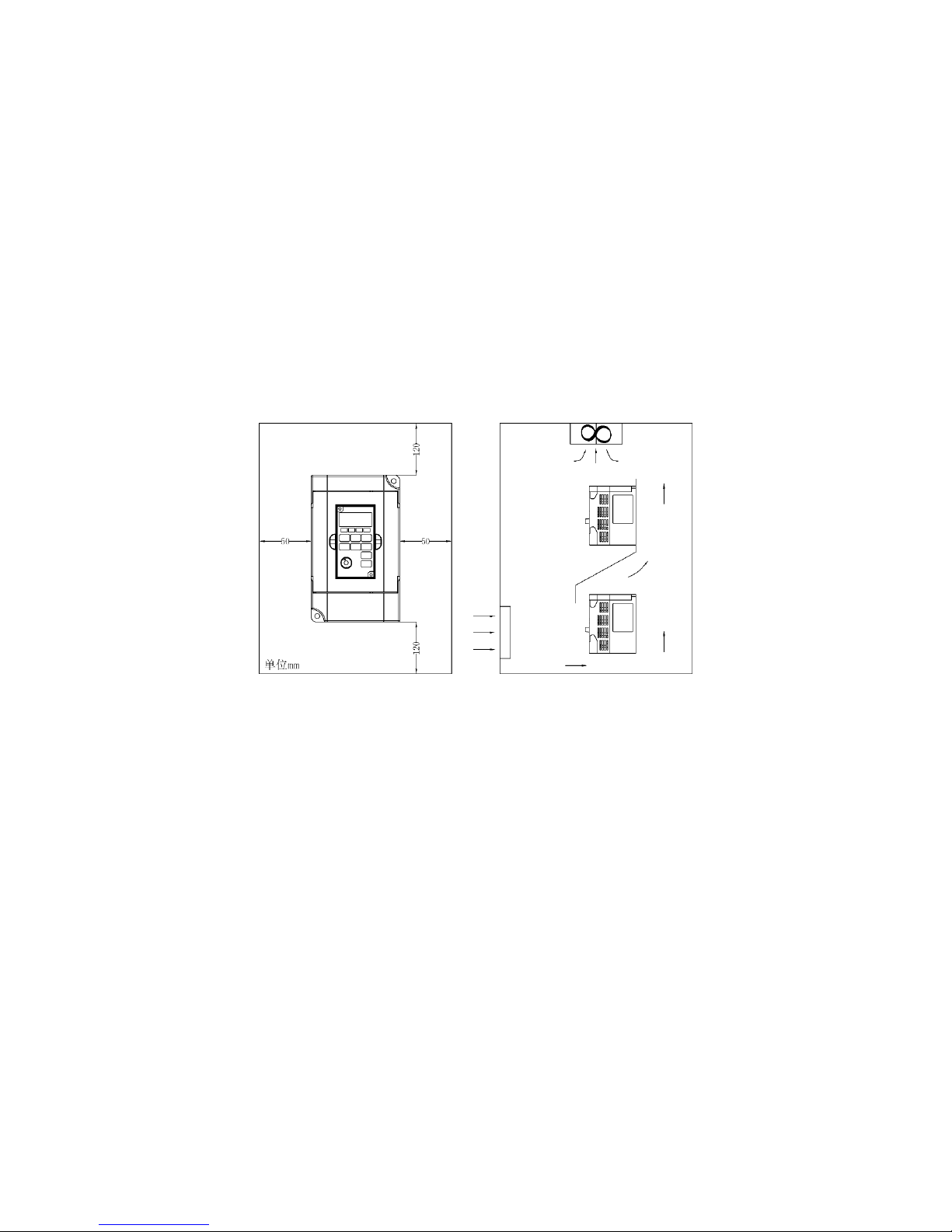
2.6 Installation and Direction
● There must be enough space left around the inverter for easy maintenance and cooling. See
Diagram;
● The inverter must be installed vertically with good ventilation for effective cooling;
● If there is any instability when installing the inverter, please put a flat board under the inverter
bottom base and install it again. If the inverter is installed on a loose surface, stress may cause
damage of parts in the main circuit so as to damage the inverter;
● The inverter should be installed on non-combustible materials, such as iron plate.
● If several inverters are installed, upper and lower, together in one cabinet, please add heat
dissipation plates and leave enough space between the inverters. See Diagram.
13
Ⅲ Wiring
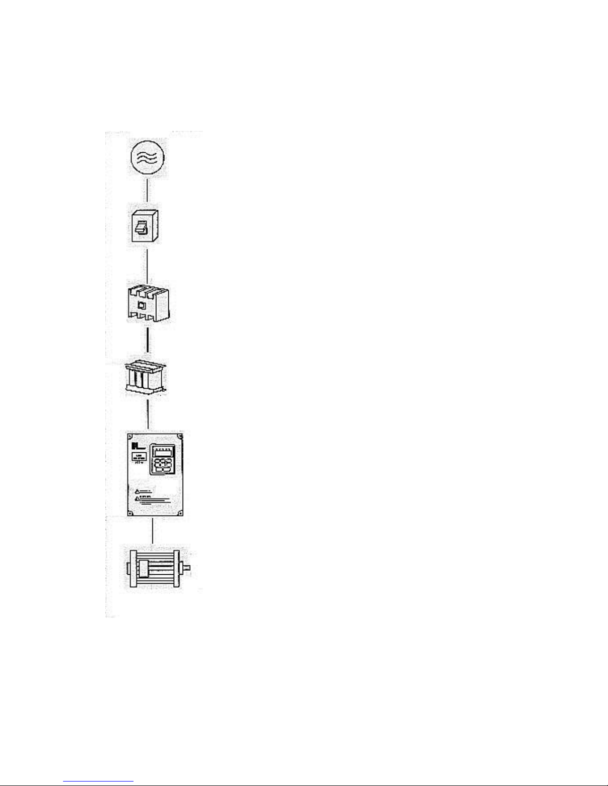
3.1 Main Circuit Wiring Schematic Diagram
Power supply:
● Verify that the inverter’s rated voltage coincides with AC power
supply voltage to avoid a damage of the inverter.
No fuse breaker:
● Refer to the related list.
Ground fault circuit interrupter:
● Use one of anti-high harmonic.
Electromagnetic contactor:
● Note: Do not use the electromagnetic contactor as the on/off
button of power supply for the inverter.
AC reactor:
●It is recommended to install an AC reactor for power factor
improvement if the input capacity is more than 1000KVA
Inverter:
●Be sure to make correct connections of the main circuit wires and
control signal wires of the inverter.
●Be sure to make correct setting of parameters for the inverter.

14
3.2 Descriptions of Terminal Blocks
1、 Arrangement of Main circuit Terminals
T S R
E
U V W R P PR
2、Arrangement of Control Circuit Terminals
FA
FB
FC DRV
FWD
REV
RST
SPL
SPM
SPH
GND
AM
VI
AI
+10
3、Function Description of Main circuit Terminals
Symbol
Function Description
R、S、T
Input terminal of AC line power.
U、V、W
Output terminal of the inverter
P+、PR
Connector for braking resistor (optional). Connector for DC reactor
E
Ground terminal
4、Function Description of Control Circuit Terminals
Symbol
Function Description
Default setting
FWD
Multi- Digital Input 1
Forward
REV
Multi- Digital Input 2
Reverse
RST
Multi- Digital Input 3
Reset
SPH
Multi- Digital Input 4
High-speed
SPM
Multi- Digital Input 5
Medium-speed
SPL
Multi- Digital Input 6
Low-speed
GND
Common & Ground
+10
Power Supply for Analog Setting
+10V
VI
Multi- Analog input
Voltage
AI
Multi- Analog input
0~20mA
DRV
Multi-Digital Output 1 (optical-
coupler)
DC24V/100mA
FA/FB/FC
Multi- Digital Output (Relay)
3A/250V
AM
Multi- Analog Output
0~10V
RS+ 、RS-
RS485 Communication port

15
3.3 Basic Connection Diagram
The wiring of the inverter is divided into two parts, main circuit terminal connections and control
circuit terminal connections. The user can see the main circuit terminals and the control circuit
terminals after removing the cover of enclosure. The terminals must be connected correctly as the
following wiring circuit diagrams.
The following diagram shows the Default setting standard connection of Model DLM1
FWD
Inverter
R
S
T
Single/Three Phase
220V
GND
DRV
W
V
U
E
VI
REV
SPH
SPM
SPL
RST
GND
+10V
GND
E
AI
Ground
terminal
FC
FA
FB
Power input
Multi- Digital Output
(Relay)
3A/250VAC
3A/30V DC
M
24V 100mA
AM
GND
Analog output
RS-485
Communication
port
1、GND
2、+5V
6、GND
5、GND
4、RS-
3、RS+
Multi-
Digital Input

16
3.4 Precautions on Wiring
(1) For the main circuit wiring:
● While wiring the sizes and specifcations of wires should be selected and the wiring should
be executed according to the electrical engineering regulations to ensure the safety.
● It is better to use shielded wire or wire and conduit for power cord and ground the shielded
layer or two ends of wire conduit.
● Be sure to install a Non Fuse Breaker (NFB) between the power supply and the input
terminals (R.S.T). (If using ground fault circuit interrupter, please choose one corresponding
to high frequency)
● Never connect AC power to the output terminal (U.V.W) of the inverter.
● Output wires mustn’t be in touch of the metal part of the inverter enclosure, or it will result
in earth short-circuit.
● Phase-shifting capacitors, LC, RC noise filters, etc, can never be connected to the output
terminals of the inverter.
● The main circuit wire must be enough far away from other control equipments.
● When the wiring between the inverter and the motor exceeds 15 meters (shielded wire) or 50
meters (No shielded wire), much higher dV/dT will be produced inside the coil of the motor,
which will cause the destruction to the interlay or insulation of the motor. Please use a
dedicated AC motor for the inverter or add a reactor at the inverter.
● Please lower the carrier frequency when there is a longer distance between the inverter and
the motor. Because the higher the carrier frequency is the bigger the leakage current of highorder harmonics in the cables will be. The leakage current will have unfavorable effect on
the inverter and other equipment.
Specifcations of Non Fuse Breaker and Wire
Model
NFB
(A)
Input wire
(mm2)
Output wire
(mm2)
Control wire
(mm2)
Screw
DLM1-0D40S2G
16
2.5
2.5
1
M4
DLM1-0D75S2G
16
2.5
2.5
1
M4
DLM1-01D5S2G
16
2.5
2.5
1
M4
Attention: The parameters in the list are only for reference and should not be regarded as standard.
(2) For control circuit wiring (signal line)
● The signal line should be separately laid in a different conduit with the main circuit wire to
avoid any possible interference.
● Please use the shielded cable with the size of 0.5-2mm2 for signal lines.
● Use the control terminals on the control panel correctly according to our needs.
(3) Grounding
● Grounding terminal E Be sure to make correct grounding 220V class: The third
grounding method (Grounding resistance should be 100Ω or lower.)
380V class: The special third grounding method (Grounding resistance should be 10Ω or
lower.)
● Choose grounding wires according to the basic length and size of the technical requirements
of the electric equipment.
● Do avoid sharing grounding wire with other large power equipment such as electric welder,

17
power machine, etc. The grounding wire should be kept away from the power supply wires
for large power equipment.
● The grounding method for several inverters together should be done as the frst and second
diagrams below. Avoid the third.
(a) Good
(b) Good
(c) Not Good

18
3.5 Optional parts
Optional parts
Function
Circuit breaker and CFCI
Wiring protected of the drive should be sure to set the circuit breaker in
the power supply side. Please use a GFCI with anti higher harmonics.
Electromagnetic contactor
In order to avoid burning the brake resistor, please set the
electromagnetic contactor used on the coil to ground surge absorber.
Surge absorbers
Absorption of electromagnetic contactor and control relays switch
inrush current.
Isolation transformer
Output and input of the isolation transformer can reduce interference.
The braking resistor
Renewable energy consumption of the motor and shorten the
deceleration time.
(1)CFCI
Within the inverte, within the motor and the input and output leads all have the capacitance of
the ground. Due to the higher carrier frequency used, the inverter earth leakage current is large,
especially the high-capacity models. When using the GFCI, sometimes our malfunction can lead
to protection circuit. So when you use of GFCI should pay attention to the GFCI selection, while
appropriate to reduce the carrier frequency, shorten lead and so on.
(2)Braking resistor
Model
Braking resistor’ s Metering
Brake torque 10% ED
Special motor
KW
W
Ω
DLM1-0D40S2G
80
200
125
0.4
DLM1-0D75S2G
100
200
125
0.75
DLM1-01D5S2G
300
100
125
1.5
Attention:
① Please select the company developed resistance value and using frequency;
② If you use not our company provided the braking resistor and braking module, which led
to the drive or other equipment damage, our ompany does not bear any responsibility;
③ When you install the braking resistor, you should consider the safety of the environment,
the flammable, and the distance is greater than 100mm converter;
④ If you want to change the resistance and power numbers, please contactwith us;
⑤ If you need a braking resistor or braking resistor,you need order separately;
⑥ Such as large mechanical inertia, please increase the capacity of the braking resistor.

19
Ⅳ Maintenance and Troubleshooting
4.1 Maintenance checks Notes
● Before maintenance check, please be sure to cut off the inverter input (RST) power;
● Make sure the power of inverter is cut off, the display disappears, and until the internal high-
voltage light is off, then you can start the implementation of maintenance, inspection;
● During the inspection, the internal power, cables and cable roots must be not pull up and
mismatch, otherwise it will lead to inverters not work;
● Do not leave any parts inside the inverter, when mounting screws and other accessories;
● After installing should keep the inverter clean, avoid dust, oil mist and moisture。
4.2 Regular inspection program
● Please make sure the voltage of supply power conforms to the required voltage of inverter;
(Especially attention to the power cable and the motor if there is damaged.)
● Please check wiring terminals and connectors, if there are loose; (Please make sure power
line terminals are not off shares.)
● Please pay attention to dust inside the inverter, iron and corrosive liquids;
● Please do not measure the insulation resistance of the inverter;
● Please check the inverter output voltage, output current, output frequency; (That can not be
much difference between the results and the rated.)
● Please check the surrounding temperature, if there is between -5 ℃ ~ 40 ℃ and the
installation environment is well ventilated;
● Humidity: maintained at 90% or less; (Can not bear water droplets.)
● Please pay attention to abnormal sound and vibration in operation; (The drive can not be
placed where vibration.)
● Please clean the vent regularly.

20
4.3 Fault information and troubleshooting
DLM series inverters have relatively complete protections including overload, phase short circuit,
to-ground short circuit, undervoltage, over temperature and overcurrent protection. When the inverter
protection triggers, please follow the information in the table below to identify the reasons.
Fault Display
Fault content and description
Approach
Acceleration-Overcurrent
1. Please check the motor for short circuit,
especially output lines;
2. Prolong acceleration time;
3. The capacity of inverter is too small, please
increase the capacity;
4. Reduce the torque increase set value.
Constant speed Overcurrent
1. Please check the motor for short circuit, and
output line insulation;
2. Check whether the motor jis jammed or
mechanical load is abruptly changed;
3. The capacity of inverter is too small, please
increase the capacity;
4. Please check if the grid voltage is abruptly
changed.
Deceleration-Overcurrent;
Stop-Overcurrent
1. Please check the motor for short circuit, and
output line insulation;
2. Increase the deceleration time;
3. The capacity of inverter is too small, please
increase the capacity;
4. DC braking is too large, please reduce the
value of DC braking;
5. Inverter failure, contact distributor.
Short circuit to ground
1. Please check the motor for short circuit, and
output line insulation;
2. Inverter failure, contact distributor.
Stop-Overvoltage
Acceleration-Overvoltage
Constant-speed-Overvoltage
Deceleration-Overvoltage
1. Increase the deceleration time, or install
brake resistor;
2. Improve grid voltage.
Blown fuse
Contact distributor

21
Fault Display
Fault content and description
Approach
Under Voltage
1. Please check the input voltage;
2. Please check if the load is abruptly changed;
3. Please make sure if there is a missing phase.
Inverter Overheat
1. Please check if the fansis stalled;
2. Please make sure the temperature is normal;
3. Please keep air convection.
Inverter overload 150%
1 minute
1. The capacity of inverter is too small, please
increase the capacity;
2. Please check the mechanical load, if there is
stuck;
3. Reset the V/F curve.
Motor overload 150%
1 minute
1. Please check the mechanical load, if there is
a sudden change;
2. The motor doesn’t match with the inverter;
3. Motor thermal insulation deterioration;
4. Voltage fluctuations;
5. Please make sure if there is a missing phase.
6. Mechanical load increases.
Motor Over-torque
1. Please check the mechanical load, if there is
sudden change;
2. The motor doesn’t match inverter;
Auxiliary coil of
electromagnetic contactor
feedback
Contact distributor
Braking transistor damage
Contact distributor
CPU fault
Contact distributor
E2Prom fault
Contact distributor

22
Er
External interference
Isolate the source of interference
Es
Emergency Stop
Emergency Stop status
20
4~20mAz
Connect break
Pr
Parameter setting error
Set parameter correctly
DCb
DC braking
DC braking status
E XX Y
Code Table:
A B C D E F G H O S N L T P R U 2
Fettle
Alarm information
Fault
S:Stop
Y A:Accelerate
N:Constant
D:Deceleration

23
Ⅴ Instruction of the Digital Operator
5.1 Description of the Digital Operator
Value
change
key
LED Display Zone
indicating For.,
Rev., frequency,
current,
revolution, etc.
Enter
key
Main Display Zone:
Indicating frequency,
current, AC V, DC V,
Forward, reverse
temperature, etc.
Run
key
Function
key
Value
change
key
Stop/
Reset
key
Potentiometer
5.2 Description of Indicator Lamp Status
1、Description of Indicator Lamp Status
Indicator lamp
Status
Description
FWD
on
The motor is in forward rotation.
REV
on
The motor is in reverse rotation.
RUN
on
Run
STOP
on
Stop
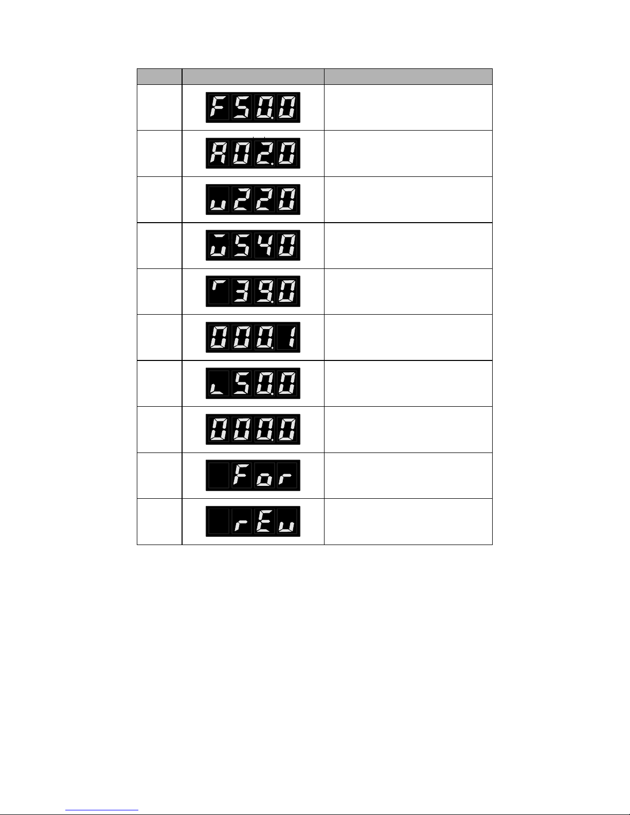
2、Description of Display Items
No.
Display
Meaning
1
Present output frequency is 50.00HZ
24
No.
Display
Meaning
2
Present set frequency is 50.00HZ
3
Present output current is 2.0A
4
Present output voltage is 220V
5
Present DC voltage is 540V
6
Present inverter’ s temperature is
39.0℃
7
Present counter’ s value
8
I Present feedback value of PID is 50%
9
Speed
10
Forward
11
Reverse
5.3 Operation Examples
1、DC voltage, temperature, counter, PID feedback value, and the speed can only be displayed after
setting specific parameter.
2、When under FWD, REV, PXXX and parameter content state, after a few seconds the display can
be automatically restored to the frequency, voltage, current, etc. interface.
3、When in running and stopping status, original interface is still shown, but the corresponding content
will vary depending on the operating conditions. Meanwhile the indicator status will change
accordingly.
4、"Confirm / left": short-press to move left; long-press to confirm.

25
Ⅵ Parameter Overview
P000 Main Frequency **
Set Range: 0.00—600.00 HZ Unit: 0.01Hz Factory Setting: 0.00
When using digital operator, the inverter will run at the setting value of P000. During running,
the running frequency can be changed by pressing the ▲ or ▼ key. During multi-speed running, the
main frequency is the first speed frequency.
When using external terminals, if P013 is set to 1, i.e. the running frequency is given by external
terminals, the first speed step is given by the potentiometer or external analog commands.
The setting of main frequency is limited by the max operation frequency.
P001 Acceleration Time
Set Range: 0.1—6500.0 Unit: 0.1s Factory Setting: 5.0
P002 Deceleration Time
Set Range: 0.1—6500.0S Unit: 0.1s Factory Setting: 5.0
Accelerat ing Time means the time needed for the inverter frequency from 0Hz to 50Hz.
Decelerating Time means time needed for inverter frequency from maximum frequency to 0Hz.
DLM1 Series inverters have 4 Accel/Decel Times. For Accel/Decel Time 2.3.4 the different
accelerating and decelerating time can be selected through the external terminals and by switching of
Accel/Decel Time according to actual needs. In the internal control multi-speed, different
Accel/Decel time can be selected through simple PLC.
P003 V/F Curve
Set Range: 0—16 Unit: 1 Factory Setting: 0
0: Wanton curve
1~16: 16 curves are wanton and available.

26

27
P004 Max. Output Voltage
Set Range: 0.1—255/510V Unit: 0.1V Factory Setting: 220/380V
P005 Base Frequency
Set Range: 0.01—600.00 Hz Unit: 0.01Hz Factory Setting: 50/60
P006 Intermediate Voltage
Set Range: 0.1—500.0V Unit: 0.1V Factory Setting: *
P007 Intermediate Frequency
Set Range: 0.01—600.00 Hz Unit: 0.01Hz Factory Setting: 2.50
P007 can set any intermediate voltage in the V/F curve. If it is set improperly, it will cause motor
over current or under torque, or even an inverter tripping.
P007 set value is limited by P005.
P008 Min. Voltage
Set Range: 0.1—50.0V Unit: 0.1V Factory Setting: * (undefined)
This parameter can set the lowest starting voltage in the V/F curve.
This setting value is limited by the voltage at the highest operating frequency.
P009 Min. Frequency
Set Range: 0.1—20.00 Hz Unit: 0.01Hz Factory Setting: *
This parameter sets the lowest starting frequency in the V/F curve.
P0010 Max Frequency
Set Range: 50.00—600.00 Hz Unit: 0.01Hz Factory Setting: 50.00
This parameter sets the highest operating frequency of the inverter

28
P011 Frequency Lower Limit
Set Range: 0.00—600.00 Unit: 0.01Hz Factory Setting: 0.00
This is set for preventing workers from false operation, avoiding overheat or some other
mechanical faults, which might be caused due to too low running frequency. When the setup frequency
is below the lower limit the inverter is running at frequency lower limit.
This set value is limited by frequency upper limit.
P012 Operation Command Source
Set Range: 0—2 Unit: 1 Factory Setting: 0
0: Digital operator;
1: External terminals or potentiometer.
IMPORTANT: CN1 JUMPER (shown at right hand side after opening inverter upper cover).
Pin 1 & 2 for panel potentiometer & Pin 2 & 3 for external terminals.
2: Communication ports, such as RS485.
P013 Operation Frequency Source
Set Range: 0—2 Unit: 1 Factory Setting: 0
0: Digital operator.
1: External terminals or potentiometer.
IMPORTANT: CN1 JUMPER (shown at right hand side after opening inverter upper cover).
Pin 1 & 2 for panel potentiometer & Pin 2 & 3 for external terminals.
2: Communication ports, such as RS485.
P014 Starting Mode
Set Range: 0—1 Unit: 1 Factory Setting: 0
Two starting modes are available for different equipment.
0: Start from the starting frequency. When P092 is set as 0, i.e. DC brake is invalid at start, it starts
running from its starting frequency. When P092 is set to any non zero value, i.e. DC brake is valid
when starting, it will first have a DC braking at start, and then start from the starting frequency. Refer
to P091 and P092.
1: Starting by Frequency track. This function can be used in the starting of large inertia load. When
starting, the inverter will trace the former speed from the set frequency downward. In case of large
inertia equipment, when restarting, it can implement the running command right away withourt
waiting for the complete stop of the equipment by tracking the former frequency to save time.
Note: When the inverter is restarted by frequency track, it will start tracking the frequency from its
set frequency downward, and search it at the highest speed. When starting, the current will be high,
and over current or stall may occur. Be sure to pay attention to the adjustment of current standard
position of frequency track. Generally, P095 should be set around 100%. The exact value should be
set according to the characteristics of mechanical load.

29
P015 Stopping Mode
Set Range: 0—1 Unit: 1 Factory Setting: 0
Two stopping modes are available for the requirements of different equipment.
0: Decelerate to stop.
When P093 is set as 0, DC braking is invalid. When DC braking is invalid, the inverter will
decelerate to the stopping frequency, and then stop output, and the motor will coast to stop. When
P093 is set for any non-zero value 0, the DC braking is valid, and the inverter will frst decelerate to
the stopping frequency, and then stop fnally by DC braking. When stopping, the DC braking is usually
used in high position stopping or for position control. Be sure to notice that frequent uses of DC
braking will cause the motor overheat.
Related parameters: P091 and P093.
1: Free-running Stop
When the inverter receives a STOP command, it will immediately stop output and the motor will
have a free running till a stop. When the free-running stopping mode is selected for the motor, DC
braking is invalid.
P016 Reverse Rotation Selection
Set Range: 0—1 Unit: 1 Factory Setting: 0
0: Reverse Run is forbidden.
1: Reverse Run is allowed.
This function is suitable when the motor cannot have reverse rotation, and to prevent workers
from false operation. When the reverse rotation is forbidden, the motor can only rotate forward, and
cannot have reverse rotation.
When the reverse rotation is forbidden, if switching between For/Rev rotation on the panel, the
panel will show Rev Run, but the motor is actually making forward rotation with the indicator lamp
indicating For Run.
P017 STOP key selection
Set Range: 0—1 Unit: 1 Factory Setting: 0
0: STOP is invalid.
1: STOP is valid.
This parameter set is only valid when P012 is set as l or 2.
When P012 is set for external terminals or communications, the STOP key on the panel can be
chosen to be valid or not. When choosing it as valid, the STOP key can stop the inverter in running.
When it needs restarting, the former running signal should be released first and then restarting is
allowable.
P018 S-Curve Time
Set Range: 0~6500S Unit: 1 Factory Setting: 0
This parameter can be set for no-impact slow start or slow stop of the inverter when starting or
stopping. When starting S-curve the inverter will make accel or decel curve of different speed rates
according to Accel/Decel Time.
When P018 is set to 0, S-curve is invalid, i.e. accelorate or decelorate in straight line.

30
Without consideration of stall, the actual Accel/Decel Time is equal to the set Acel/Decel Time
plus S-curve Time.
P019 Carrier frequency (Note: 0 ~ 15 corresponding to 0 ~ 16K Hz)
Set Range: 0~15 Unit: 1 Factory Setting: 10
The carrier frequency has some affect on the electromagnetic noise of the motor, and meanwhile
the level of the carrier frequency has certain relation with the heating capacity of the inverter and the
interference to the environment.
See the following table:
Carrier
Frequency
Electromagnetic
Noise
Heating
Capacity
Interference to the
Environment
Low
High
High
Low
Small
Large
Little
Great
Carrier frequency corresponding table:
Set Value
0 1 2 3 4 5 6 7 8 9 10
11
12
13
14
15
Carrier
Frequency
KHz
1.5 2 3 4 5 6 7 8 9
10
11
12
13
14
15
16
As shown in the table above, with a higher carrier frequency, the electromagnetic noise will be
lower, but the interference to othersystems must be prevented. With a lower carrier frequency, the
electromagnetic noise will be a little higher, but the heating capacity will be small. So the carrier
frequency should be set as low as possible, especially with large power machines, if the noice demand
is not so high.
P020 Starting Frequency
Set Range: 0.1—10.0 Hz Unit: 0.1Hz Factory Setting: 0.5
Starting frequency is the initial frequency when the inverter is started. If the starting frequency is
set to 4.0Hz, the inverter will begin to run at 4.0Hz .
P021 Stopping Frequency
Set Range: 0.1—10.0 Hz Unit: 0.1Hz Factory Setting: 0.5
When the inverter receives a stop command, it will immediately decelerate to the stopping
frequency, stop output or start DC brake to a final stop.
If P093 is set to 0, DC brake is invalid when stopping and the inverter will stop output.
If P093 is set to any other parameter except “0”, DC brake is valid; the inverter will stop by DC
braking.
P022 Jog Frequency
Set Range 0.00—600.00 Unit: 0.01Hz Factory Setting: 5.00
This parameter can realize the jogging function when the inverter is tested. The jog operation can
be achieved only through the external terminals, which can be set by multi-function input terminals.
Jog frequency is limited by frequency lower/upper limit. While the jog function is implemented, other

31
commands are invalid. The acceleration time of jog frequency is set by P023. When using jog function,
set external terminals to 07 or 08.
This function is only valid at stop condition. It is invalid at running. When P012 is set to 1, it is
valid.
P023 Jog Accel/Decel Time
Set Range: 0.1—25.0 Unit: 0.1S Factory Setting: 1.0
P023 corresponds to Accel/Decel Time of 0~50Hz.
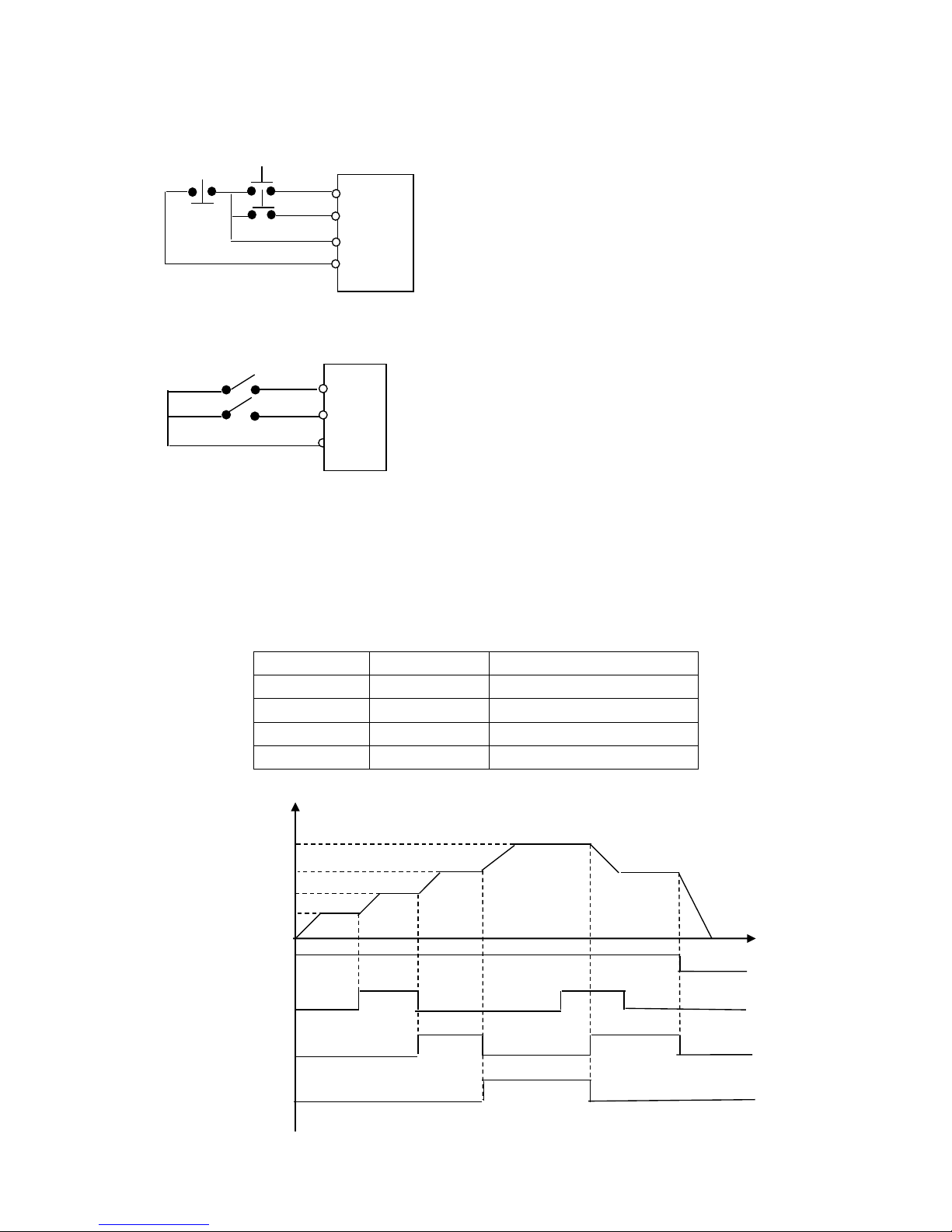
P024 PLC Operation
Set Range: 0—5 Unit: 1 Factory Setting: 0
0: Normal;
1: External 4 –speed control (refer to P050~P055);
2: External multi-speed control;
Multi-function Terminals
Results
Multi-speed 1
Multi-speed 2
Multi-speed 3
OFF
OFF
OFF
Main frequency & set by P000
ON
OFF
OFF
Multi-speed 1 & set by P035.
OFF
ON
OFF
Multi-speed 2 & set by P036.
ON
ON
OFF
Multi-speed 3 & set by P0375.
OFF
OFF
ON
Multi-speed 4 & set by P038.
ON
OFF
ON
Multi-speed 5 & set by P039.
OFF
ON
ON
Multi-speed 6 & set by P040.
ON
ON
ON
Multi-speed 7 & set by P041.
Note:
(1) To realize excternal 8-speed control, it is only valid when Multi-input is set for Multi-speed 1, 2,
3 and P024 is set to 2.
(2) Multi-speed 1, 2, 3 can make up to 7 speeds. Adding the main frequency it will have 8 speeds.
(3) The frequencies of Speed 1 ~ Speed 7 are determined by P035~P41.
(4) Each Acel/Decel Time is determined by the external multi-function terminal.
(5)The directions of each program running are determined by the external multi-function terminals.
(6) The main frequency can be set by P000 or the potentiometer.
Multi-speed1
Multi-speed2
Multi-speed3
FWD
Main
T
F

32
3: Transverse movement
This is a special parameter in the chemical fiber and printing and dying industries to realize transverse
movement. Except the commands of stop, external faults and emergency stop all other commands will
not be accepted at running.
F
P000 P041
P043
P042
P035 P041
T
Note:
(1) The frequency at each inflection point is determinded by P000 and P035.
(2)Skip Frequency is determined by P041.
(3)Running Time is determined by Timer P042 and P043.
(4)Restart after power off. The running status of frequency will not be memorized.
4: Internal Multi-speed control
F
P042 P043 P044 P045 P046 P047 P048 P049 T
Note:
(1) Main speed and 7-speeds compose 8-speeds.
(2) Acel/Decel Time of each speed is set by PLC Acel/Decel Time P027 and P028.
(3) Running Time is set by Timer P042~P049. Set timer to 0 if not used.
(4) Running direction of each speed is determined by P026.
(5 Restart after power off from the main speed. Status before power off will not be memorized.
5: Drawing
This is a special parameter for the constant speed of unwinding and rewinding. By using this function
the linear speed can maintain constant at certain accuracy levels.
T
P035
P036
P000
Mult-input
Multi-output

33
Note:
(1) Triggered by external multi-function terminals and the drawing actions begin to be implemented.
(2) Actual running time is T=P042×10;
(3) When the drawing is finished the inverter will output at a constant speed set by P036 and the
corresponding multi-ouput terminals will activate. Until receiving the Stop command the inverter will
stop running and the multi-ouput terminals will reset.
(4) In case of P133=1, it has the memory function at power off. When it restarts after the power off
the prior status will be memorized.
(5) The output frequency for drawing can be either up or down.
P025 Auto PLC Operation (internal multi-speed)
Set Range: 0~3 Unit: 1 Factory Setting: 0
Note:
This parameter is only valid when P024 is set to 4. For relevant parameters, refer to P000, P024,
P035~P049.
0: Stop after the program runs for one cycle and restart only when another running cammand is given.
1: Loop Run. When the running command is given, the inverter starts to operate in sequence with the
speeds and times set by each internal parameter for infinite loops. During the loop run, except the
commands of stop, external faults and emergency stop, all other commands will not be accepted.
F P036
P037 P040
P000 P041
P038
P039
P035 T
P042 P043 P044 P045 P046 P047 P048 P049
2: Stop after the program runs automatically for one cycle & stop at intermediate intervals beween
different speeds.
(1) When the command of automatic program running is given the inverter will operate according to
each parameter, but it will stop frst and then restart at the change of each stage. It will stop
automatically after running for one cycle. Only with another running cammand is given the inverter
can restart.
(2) The frequencies of each speed are set by P000, P035~P041.
(3) The running times of each speed step are set by P042~P049.
(4) The running direction is set by P026.
3: Loop run & stop at intermediate intervals beween different speeds.
(1) After the auto run command is given the inverter will run according to the parameters, but at every
change of speed it will stop frst and then start again. It will continue and stop until the OFF command
for auto run is given.

34
(2) When each speed is fnished the corresponding multi-function output will act.
(3) When each pattern run is fnished the corresponding multi-function output will act.
(4) The width of output pulse is 20 ms.
(5) When running again after power off all the actions will be started from the beginning and the
previous states will not be memorized.
P026 PLC Rotation Direction
Set Range: 0~255 Unit: 1 Factory Setting: 0
This parameter is only valid when P024 is set to 4.
This parameter determines the rotation directions of each frequency step of P035~P041 and P000
in the pattern run. The setting method is as follows:
The rotation direction is set frst in the binary bit mode, and then converted to a decimal value
for the setting of this parameter.
For instance:
bit 0-7
7 6 5 4 3 2 1
0
0 1 0 0 1 0 1
0
0: For 1: Rev
Main Speed (P000) For
Step 1(P035) Rev
Step 2(P036) For
Step 3(P037) Rev
Step 4(P038) For
Step 5(P039) For
Step 6(P040) Rev
Step 7(P041) For
The parameter value 01001010 is converted to a decimal value:
1×26+1×23+1×21=64+8+2=74
Then P026=74
P027 PLC Accel. / Decel. Time 1
Set Range: 0~65535 Unit: 1s Factory Setting: 0
P028 PLC Accel. / Decel. Time 2
Set Range: 0~65535 Unit: 1s Factory Setting: 0
This parameter is only valid when P024 is set to 4.
This parameter is to determine the accel/decel time values of Step 1~4 of the internally controlled
multi-speed. Its setting method is as follows:
(1) Determine each accel/decel time in in the binary 2 bit mode
Bit1
Bit0
Accel/Decel Time
0
0
Accel/Decel Time 1: P001、P002
0
1
Accel/Decel Time 2: P029、P030
1
0
Accel/Decel Time 3: P031、P032
1
1
Accel/Decel Time 4: P033、P034

35
(2) Determine the accel/decel time of each speed step in the binary 8 bit mode
Speed No. 4
Speed No. 3
Speed No. 2
Speed No. 1
t4
t3
t2
t1
0 1 1 0 0 0 1
1
t1 select Accel. Time 4 t3 select Accel. Time 3
t2 select Accel. Time 1 t4 select Accel. Time 2
1×20+1×21+1×25+1×26=99
Then P027=99
P028 is set in the same way as P027.
P029 Accel. Time 2
Set Range: 0.1~6500S Unit: 0.1S Factory Setting: 10.0
P030 Decel. Time 2
Set Range: 0.1~6500S Unit: 0.1S Factory Setting: 10.0
P031 Accel. Time 3
Set Range: 0.1~6500S Unit: 0.1S Factory Setting: 50.0
P032 Decel. Time 3
Set Range: 0.1~6500S Unit: 0.1S Factory Setting: 50.0
P033 Accel. Time 4
Set Range: 0.1~6500S Unit: 0.1S Factory Setting: 100.0
P034 Decel. Time 4
Set Range: 0.1~6500S Unit: 0.1S Factory Setting: 100.0
P035 Frequency 2 Factory Setting: 15.0
P036 Frequency 3 Factory Setting: 20.0
P037 Frequency 4 Factory Setting: 25.0
P038 Frequency 5 Factory Setting: 30.0
P039 Frequency 6 Factory Setting: 35.0
P040 Frequency 7 Factory Setting: 40.0
P041 Frequency 8 Factory Setting: 0.50
Set Range: 0.0~600.0Hz Unit: 0.1Hz
P042 PLC Timer 1 Set Factory Setting: 10.0
P043 PLC Timer 2 Set Factory Setting: 10.0
P044 PLC Timer 3 Set Factory Setting: 0.0
P045 PLC Timer 4 Set Factory Setting: 0.0
P046 PLC Timer 5 Set Factory Setting: 0.0
P047 PLC Timer 6 Set Factory Setting: 0.0
P048 PLC Timer 7 Set Factory Setting: 0.0
P049 PLC Timer 8 Set Factory Setting: 0.0
Set Range: 0.0~6500S Unit: 0.1S

36
P050 Multi-Input FOR Factory Setting: 02
P051 Multi-Input REV Factory Setting: 03
P052 Multi-Input RST Factory Setting: 10
P053 Multi-Input SPH Factory Setting: 17
P054 Multi-Input SPM Factory Setting: 18
P055 Multi-Input SPL Factory Setting: 19
Set Range: 00~32 Unit: no
00: Invalid: When the terminal is set for null, it can avoid faulse operation.
01: Run: It can be combined with other terminals to combine various control methods.
02: FWD Forward rotation
03: REV Reverse rotation
04: STOP
05: FWD/REV
06: JOG
07: Jog Forward rotation
08: Jog Reverse rotation
09: Emergency Stop: It can receive external emergency stop or other fault signals.
10: RST This terminal can be used to reset after the fault is removed.
12: Overheat of radiator or motor: This contact can be used to detect overheat of the radiator or
motor to protect the motor and inverter.
13: Externally Controlled Timer 1 start: When the contact is closed, the timer will start and begin to
count time. When the timer reaches the point the responding multi-outputs will act.
14: Externally Controlled Timer 2 start
17: High Speed: High, middle and low speed can compose three kinds of different operation patterns.
18: Middle Speed: In the three terminals the high-end signal has priority.
19: Low Speed: Determined by Frequency 3, 4.
20: Multi-speed 1 Multi-speed 1, 2, 3 can compose 7-Steps.
21: Multi-speed 2
22: Multi-speed 3
23: Acel/Decel Select 1: This terminal can be used to selcect the acel/decel time of the inverter.
24: Acel/Decel Select 2:
25: UP function: When this terminal switch acts the frequency will increase by one unit.
26: DOWN function: When this terminal switch acts the frequency will decrease by one unit.
27: Counter: When the terminal is set for the counter it can receive the pulse signal of ≤250HZ
and count the number.
28: Counter reset: the action of this contact can clear the present counting value.
29: Drawing start: When the contact is triggered the action of drawing will start.
31: Auto PLC reset suspend: This contact can be used to realize the function of suspending clearup of Auto PLC.
32: PID valid: PID becomes valid and working.
A. Using the three multi-function terminals to form the connection method of three-wire system for
the realization of switching FWD/REV, which is extentively applied in the case of switching
37
FWD/REV of photoelectric switches.
B. Use RUN, GND, FWD/REV to combine for Starting, Stopping and For/Rev:
C. Description of Accel/Decel Time 1 and 2 Select
It is only valid when P024 is set to 0, 1, 2.
Any two multi-function input terminals can be combined to 4 kinds of Accel/Decel for selection.
The related multi-function input terminals are set to Accel/Decel Select 1,2.Take the terminals of
SPH and SPM as example, when the terminals of SPH P053 is set to 23 and the terminals of SPM
to 24, then the terminals of SPH and SPM should be Accel/Decel Time 1, 2 Select.
SPH Terminal
SPM Terminal
Result
OFF
OFF
Accel/Decel Time 1
ON
OFF
Accel/Decel Time 2
OFF
ON
Accel/Decel Time 3
ON
ON
Accel/Decel Time 4
D. Function description of High, middle and low terminals:
F
H.S
.M.S
.
L.S.
M.F.
RUN COMMAND
L.S.
M.S.
FWD
REV
RST
GND
STOP
RUN
P012=1; P050=02
P051=03; P052=04
When triggering FWD, the inverter will rotate forward
(starting);
When triggering REV, the inverter will rotate reversely;
When pressing STOP, the inverter will stop.
FWD
REV
GND
K1
K2
Select the terminals of FWD and REV
Parameter setting: P012=1 to set the exterminal control.
P050=01 to set RUN
P051=05 to set F/R
When K2 is open it rotates forward, while K2 is closed it
rotates
H.S.

38
RUN
SPL
Terminal
SPM
Terminal
SPH
Terminal
Result
ON
OFF
OFF
OFF
Main frequency and frequency run with the
set value of P000.
ON
ON
OFF
OFF
Low speed and frequency run with the set
value of P035.
ON
ON/OFF
ON
OFF
Intermediate speed and frequency run with
theset value of P036.
ON
ON/OFF
ON/OFF
ON
High speed and frequency run with the set
value of P037.
E. Description of UP and DOWN Function
Max. Ope. Frequency
Set Frequency
F. lower limit
Up Command
Down Command
UP
DOWN
Result
ON
OFF
Frequency up
OFF
ON
Frequency down
ON
ON
No up, no down
Note:
⑴ The function of UP and DOWN is only valid when the operation of Operator is delected
for the source of the running frequency, i.e. P013=0.
⑵ When UP is closed the inverter’ s frequency will increment.
⑶ When DOWN is closed the inverter’ s frequency will decrement.
⑷ When both UP and DOWNare closed at the same time the frequency will neither increase
nor decrease. It is regaded as invalid.
⑸ When the frequency reaches the max. operation frequency it will not increase.
⑹ When the frequency reaches the min. frequency or its lowe limit, it will not decrease.
⑺ It has the function of memory, including the memory for power-off. (Setting P60=1)
⑻ When adopting the function of UP and DOWN, its up and down speed rate is determined
by the present Accel/Decel time.
⑼ When keeping pressing UP or DOWN,the frequency will increase or decrease rapidly.
⑽ The function of UP and DOWN is valid in operation, not during standy by.
39
F. Description of Multi-speed 1, 2 and 3 Functions
They are only valid when P024 is set to 2. Details refer to P024.
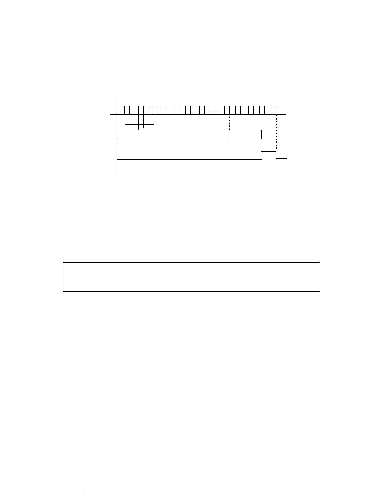
G. Description of Counter Function
cn
t1 S2
Value reach
Value reset
Note:
⑴ The signal width triggered should not be lower than 2msec(t1、S2≥2msec);
⑵ When the counting value is reached the corresponding multi-functionoutput contact will act.
⑶ This counter is reverse counter. When the counter is reset the setting value will be displayed and
then start counting.
⑷ When the counting value is reached the displayed value is 0. It will not count againand only start
counting after it reset.
⑸ It has the function of memory. When P132=1, the counting result can be memorized for power-off.
P056 Multi-Output DRV Factory Setting: 01
P057 Multi-Output FA, FB, FC Factory Setting: 02
Set range: 00—32 Unit: nil
00: Invalid. When the terminal is set for no function it can prevent false action.
01: Running. The contact will act when the inverter is running or receiving running command signals.
02: Fault indication. The contact will act when the inverter detects abnormal condition.
03: Zero Speed: The contact will act when the output frequency is lower than starting frequency.
04: DC Braking indication: The contact will act when the inverter is in DC braking condition.
05: Set Frequency reach: The contact will act when the output frequency reaches the set frequency.
06: Random Frequency 1 Reach: The contact will act when the output frequency reaches the
designated frequency (P070).
07: Random Frequency 2 reach: The contact will act when the output frequency reaches the
designated frequency (P071).
08: In Accel: The contact will act when the inverter is in acceleration status.
09: In Decel: The contact will act when the inverter is in deceleration status.
10: Inverter Overload alarm: The contact will act when the inverter detects overload.
11: Motor Overload alarm: The contact will act when the inverter detects overload of motor.
12: Over-torque detect: The contact will act when the inverter detects over torque.
13: Undervoltage alarm: The contact will act when the inverter detects under voltage.
14: Single Step end: The contact will act and output a pulse when the inverter fnishes a single step.

40
15: Process end: The contact will act and output a pulse when the inverter finishes all the steps in
implementation of pattern operation (i.e. after one cycle).
16: Set Counter reach: The contact will act when the inverterimplements the external counter and
the counting value is equal to the set value (P064).
17: Intermediate Counter reach: The contact will act when the inverter implements the external
counter and the countingvalue is more than or equal to the set value (P065).
18: Externally Controlled Timer 1 reach: The contact will act when the timer reaches the set value.
19: Externally Controlled Timer 1 reach
20: 4∽20mA disconnected. When the AI input signal is opend the contact will act.
27: Drawing Reach: The contact will act when the drawing action is fnished. The contact will
automatically reset when the inverter stops.
28: PID Lower Limit alarm: This contact will act when the PID feedback quantity is lower than the
lower limit (P108).
29: PID Upper Limit alarm: This contact will act when the PID feedback quantity is higher than the
upper limit (P107).
30: Fan run: When the inverter is working in high temperature or in running, this contact will act.
31: Electromagnetic Relay act: When the contact pulls in the corresponding multi-function terminal
will act.
32: Braking Resistor act: When the inverter in running and the DC voltage reaches the braking
voltage the contact will act.
P058 Multi output AM
Set Range: 0~7 Unit: 1 Factory Setting: 0
Function: In combination with P059 it can be connected to a frequency meter with the measuring
range of 0~10V for external monitoring.
0: Analog Output: 0~10V corresponds to 0~ Max operation frequency.
1: Analog Output: 0~10V corresponds to 0~ 2 times Rated current.
2: Analog Output: 0~10V corresponds to 0~1000V DC voltage.
3: Analog Output: 0~10V corresponds to 0~510/255V output AC voltage.
4: Pulse Output: 1 Pulse/Hz.
5: Pulse Output: 2 Pulse/Hz.
6: Pulse Output: 3 Pulse/Hz.
7: Pulse Output: 6 Pulse/Hz.
P059 AM Analog Output Gain
Set Range: 0~100% Unit: 1% Factory Setting: 100%
This parameter can be used to adjust the output voltage value of the multi-output AM to suit
frequency meter with different measuring range and also used to adjust a frequency meter. For example,
for an externally connected frequency meter with the measuring range of 0~5V, a multi-function
terminal can be used to display its operation frequency. Then user can set P059=50.
*Note: When selecting a frequency meter please select one with measuring range below 0~10V.
P060 Up-down Mode
Set Range: 0~1 Unit: 1 Factory Setting: 0

41
0: Not memorized
1: Memorized
Through the setting of this parameter whether the value changed by UP-DOWN will be
memorized after stopping can be selected.
When P060 is set to 1, if restart after stopping, the value at stopping will be memorized. If restart
after power off, the values at power off will not be memorized, but the value set by P000 will be
memorized. When P060 is set to 0, if restart after stopping, it will return to the value of P000, the value
changed by up-down will not be memorized.
P062 Timer 1 Time
Set Range: 0.0~10.0 Unit: 0.1S Factory Setting: 0
P063 Timer 2 Time
Set Range: 0~100 Unit: 1S Factory Setting: 0
Timer 1 is a timer of 0.1S~10.0S and Timer 2 is a timer of 1S~100S.
When the timer for multi-input terminal is opened or closed the timer starts to count time. When
the set time is reached the corresponding multi-output contact will act. When the timer is cut off, the
timer for multi-output will reset. During running, if the machine stops due to fault, the timer will count
time normally and not suspend; if the machine stops due to power off, the timer will reset automatically.
P064 Counter
Set Range: 0~9999 Unit: 1 Factory Setting: 0
An external terminal of multi-function can be used as a trigger for the counter. When the counter
reaches set value P064 the corresponding multi-function output contact will act. After the counter is
reset and returns it will start counting again. A proximity switch or optoelectronic switch can be used
for the trigger signals.
P065 Intermediate Counter
Set Range: 0~9999 Unit: 1 Factory Setting: 0
Intermediate Counting Value is one value within counting range. When the counter reaches this
value the corresponding multi-function output contact will act and output one pulse signal. It is valid
when the set value of P065 is smaller than P064.
P066 Skip Frequency 1
P067 Skip Frequency 2
P068 Skip Frequency 3
Set Range: 0.00~600.00Hz Unit: 0.1Hz Factory Setting: 0.0
P069 Skip Frequency Range
Set Range: 0.1~10.00Hz Unit: 0.1Hz Factory Setting: 0.5
F
P068 Frequency
P067 P069
P066 P069

42
To avoid a mechanical resonance point three frequency skip points are set. In case of P069=0,
all skipping frequencies are invalid. The actual skipping frequency range is 2 times that of P069, as
shown in the above diagram.
P070 Random Frequency 1
P071 Random Frequency 2
Set Range: 0.00~600 Unit: 0.1Hz Factory Setting: 0.0
P072 Analog Input Select
Set Range: 0~4 Factory Setting: 0
0: 0~10V 1: 0~5V 2: 0~20mA 3: 4~20mA 4: 0~10V and 4~20mA stacked
This parameter can be set to satisfy different analog input signals.
When P072=4, output frequency =(U/Umax + I/Imax)*50Hz/2
Among which: U: Analog Quantity Voltage Quantity; Umax: Maximum Analog Quant ity
Voltage Quant ity; I: Analog Quantity Current Quantity; Imax: Maximum Analog Quantity
Current Quantity.
For example, When +10V and 20mA are respectively entered, the output frequency of the inverter is
50Hz.
(In case the max. operation frequency is set to 50Hz)
P073 Analog Low End Frequency
Set Range: 0.0~600.0Hz Unit: 0.1Hz Factory Setting: 0.0
P074 Bias Direction of Low End Frequency
Set Range: 0~1 Factory Setting: 0
0: Forward dirction
1: Reverse direction
P075 Analog High End Frequency
Set Range: 0.0~600.0Hz Unit: 0.1Hz Factory Setting: 51.0
P076 Bias Direction of High End Frequency
Set Range: 0~1 Factory Setting: 0
0: Forward dirction
1: Reverse direction
P077 Analog Negative bias Reverse
Set Range: 0~1 Factory Setting: 0
0: Negative bias Rev is not allowable.
1: Negative bias Rev is allowable.
The parameter is to measure the range and zero point of the external analog terminals and can be
combined for any kind of curve to control the operation of the motor.
Examples:

43
Rev. Area 50 Hz For. Area
0 5V 10V
4mA 12mA 20mA
F
50
0 10V
4mA 20mA
F
40
0V 2V 10V
4 20mA
10
40
F
0V 2V 10V
4mA 4.8mA 20mA
10
P078 Analog Filtering Constant
Set Range: 0~50 Unit: 1 Factory Setting: 20
The setting of this parameter is related to the responding speed of analog commands. The higher
the value of P078 is set, the slower the responding speed of analog commands. Too low setting of
P078 may cause the instability of frequency with fluctuation.
P079 Overvoltage Stall Prevention
Set Range: 0~1 Unit: 1 Factory Setting: 1
0: Overvoltage stall prevention function is invalid.
1: Overvoltage stall prevention function is valid.
Setting: P073=50
P074=1
P075=50
P076=0
P077=1
P073=50
P074=0
P075=0
P076=0
P073=10
P074=1
P075=40
P076=0
P077=1
P073=10
P074=1
P075=40
P076=0
P077=0

44
When the inverter is in decelerating, due to the effect of load inertia, the motor will produce a
return energy to the inverter and cause the DC voltage of the inverter to increase. So when the function
of overvoltage stall prevention is set valid and the DC voltage of the inverter becomes too high, the
inverter will stop decelerating till the DC side voltage decreases to its rated value, then the inverter
will go on to execute deceleration and the deceleration time will be extended automatically.
* Note: When the output voltage is higher the inverter will become abnormal or turn to
protection. In such case P079 can be set to 0 (Invalid), which is easy to cause overvoltage protection.
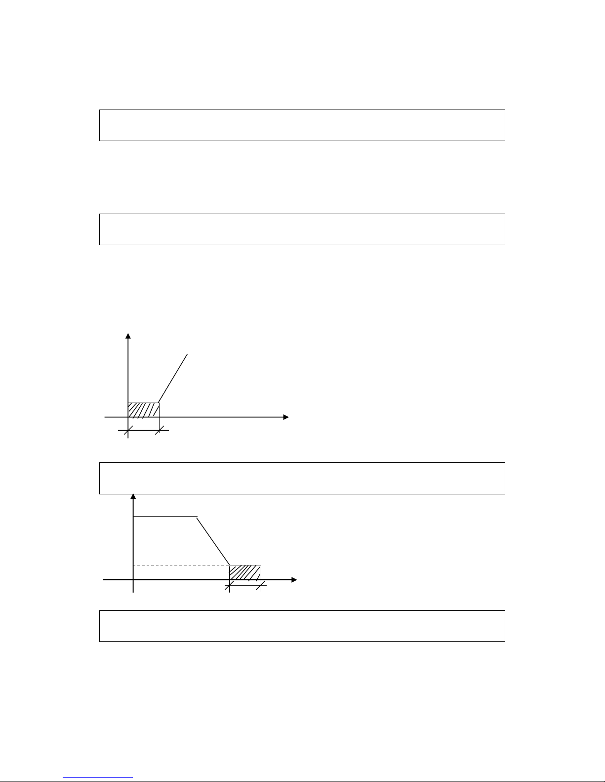
P080 Stall Prevention Level during Acceleration
Set Range: 0~200% Unit: 1% Factory Setting: 150
When the inverter is in accelerating, due to over load or too short acceleration time, the output
current of the inverter will go up quickly and exceed the rated standard level. When this happens, the
inverter will stop accelerating until the current returns under its rated value, will the inverter go on to
accelerate. When using the frequency track function the value of P080 should be lowered properly.
The greater the load initia quantity is, the smaller the value of P080 should be set. Otherwise it is
extremely easy to cause overcurrent protection.
I
Stall Prev. Level
Output frequency
T
100% current is the rated current of the motor. When this parameter is set to 0, the stall prevention
function is invalid.
P081 Stall Prevention Level at Constant Speed
Set Range: 0~200% Unit: 1 Factory Setting: 0
When the inverter is in constant running, due to load fuctuation and other reasons, the current
will go up. When the current exceeds its rated value, the inverter will lower the output frequency.
When the output current returns to its normal range the inverter will accelerate again to its set
frequency.
Stall prevention level
during running
Output frequency
T
100% current is the rated current of the motor. When this parameter is set to 0, the stall prevention
function is invalid.

45
P082 Stall Prevention Level during Deceleration
Set Range: 0~200% Unit: 1 Factory Setting: 180
When this parameter is set to 0, the stall prevention function is invalid.
P083 Overtorque Detect Level
Set Range: 0~200% Unit: 1% Factory Setting: 0
When the output current exceeds the over torque detection level and also exceeds half of the set
over torque detection time (factory setting: 1.0s), the over torque detection will begin to indicate, and
the corresponding multi-function contact will act. When it exceeds the set time value, the inverter will
turn into self-protection. But when this parameter is set to 0, the over torque detection will be invalid.
P084 Overtorque Detect Time
Set Range: 0.1~20.0S Unit: 0.1S Factory Setting: 1.0
When the inverter detects that the output current has exceeded the motor current set value, the
inverter begins to calculate the over torque time. When the over torque time has exceeded half of the
over torque detection time, the corresponding multi-function output contact will act, the over torque
alarm will be produced, while the inverter will continue running. When the over torque time has
exceeded the set detection time (set by P083), the inverter will turn into self-protection, display the
fault signal and stop output.
P085 Rated Motor Voltage
It is set according to the rated voltage value of the namplate. For 230V class inverters the default is
220, while for 400 V class inverters the default is 380V.
P086 Rated Motor Current
It is set according to the rated value of the namplate. This parameter can be used to restrict output
current of the inverter to prevent overcurrent and protect the motor. If the current of the motor has
exceeded this value the inverter of AC motor will turn into self-protection.
P087 Motor Poles
Set Range: 02~10 Unit: 1 Factory Setting: 04
This parameter is set for the pole number of the motor according to the namplate of the motor.
P088 Rated Motor Revolution
Set Range: 0~9999 Unit: rpm Factory Setting: 1440
This should be set according to the actual revolution of the motor. The displayed value is the
same as this parameter. It can be used as monitoring parameter, which is convenient to the user. This
parameter set value corresponds to the revolution speed at 50Hz.
P089 Motor No-load Current
Set Range: 0~100 Unit: 1 Factory Setting: 40
The setting of Motor no-load current will affect the quantity of slip compensation. 100% current
is the rated current of the motor.
P090 Slip Compensation
Set Range: 0~1.0 Unit: 1 Factory Setting: 0.0
When the inverter drives the motor, the slip will become bigger due to the increase of load. This
46
parameter can be set for slip compensation to decrease the slip and make the running speed of the
motor closer to synchronous speed of revolution.
P091 DC Braking Voltage
Set Range: 0.0~20.0% Unit: 0.1% Factory Setting: 2.0
This parameter is set for the DC brake voltage to of the motor at starting and stopping. It can be
adjusted for different brake voltage. When adjusting the parameter it must be increased slowly from
lower values to high values until the suffcient brake torque is achieved.
100% voltage is the voltage at maximum frequency.
P092 DC Braking Time at Starting
Set Range: 0.0~25.0S Unit: 0.1S Factory Setting: 0.0
This parameter is set for DC Brake at starting and giving the lasting time of DC Brake current of
the motor at starting. If it is set to 0 it means DC brake is invalid.
DC braking before running is normally applied in the cases in which the load is movable in the “stop”
state, such as windmill and other machines. Because of the load existing before the inverter drives, the
motor is always in a free running state, with an uncertain running direction. So the DC braking can be
executed before starting the motor to prevent the inverter from tripping.
P093 DC Braking Time at Stopping Set
Set Range: 0.0~25.0S Unit: 0.1S Factory Setting: 0.0
P094 Frequency track Time
Set Range: 0.0~20.0S Unit: 0.1S Factory Setting: 2.0
This parameter is set as frequency track time when the inverter restarts by the frequency track
method after the external errors or temporary power off. For the starting and stopping of some large
inertia load, because of its large inertia, if restarting the machine after its complete stop, it will waste
much time. But if the frequency track function is started, it is not necessary to wait for the machines
to come to a full stop for restart. The inverter will search the speed from high to low with the set
F
P020
P092
T
T
F
P020
P093
Th is setting is valid only when P014 is set
to 0. Related introduction refer to P014.
This parameter is valid when
P015 is set to 0. The related
parameters see P015.

47
frequency.
After tracking it it will continue to accelerate to reach the set frequency.
P095 Frequency track Current Level
Set Range: 0~200% Unit: 1% Factory Setting: 150
When the inverter search speed this set value sould be taken as the level for output current. When
the output current is higher than this level the inverter will suspend searching. When the current is
restored below the current level it will then execute the frequency track again.
After starting the frequency track please decrease properly the frequency track current level
according to the actual conditionof load. Otherwise it is extremely easy to cause overcurrent protection.
P096 Restart after Instantaneous Stop
Set Range: 0~1 Factory Setting: 0
0: Invalid, i.e. the inverter will not restart after an instantaneous stop.
1: Frequency track Start. Refer to P094.
P097 Allowable Power-off Time
Set Range: 0.1~5.0S Unit: 0.1S Factory Setting: 0.5
This parameter is set for the maximum allowable power off time. If exceeding the set time the
inverter will continue to stop input after power on. To execute the restart it needs to follow the general
starting procedures.
*Attention: When using this function special attention should be paid to the safety. During the
process of instantaneous power off and power on the inverter may restart. It is easy to produce danger.
Be careful to use this function.
P098 Number of Abnormal Restart
Set Range: 00~10 Unit: 1 Factory Setting: 00
After the abnormal conditions (such as overcurrent, overvoltage) happen the invrter will
automatically reset and restart. If the starting mode is set for general mode it will start according to
the general mode. If it is set for frequency track start it will start in the frequency track mode. After
start it will restore the set number again if there is not anything unusual happened within 60 seconds.
If there is any error and it reaches the set number the inverter will not have input. It can only be started
after reset. If P098 is set to 0 the inverter will not carry out the functions of automatic reset and restart.
P099 Auto Voltage Regulation
Set Range: 0~1 Unit: 1 Factory Setting: 1
0: Invalid
1: Valid
When the input power supply is not stable and if the voltage is over high the operation of the
motot with the power of exceeding the rated voltage will cause the temperature of the motor increasing,
the insulation damaged and the output torque unstable. This auto voltage regulation can automatically
stablize the output voltage within the rated voltage range of the motor under the condition of unstable
output power supply
When this function is set to invalid the output voltage will fluctuate.
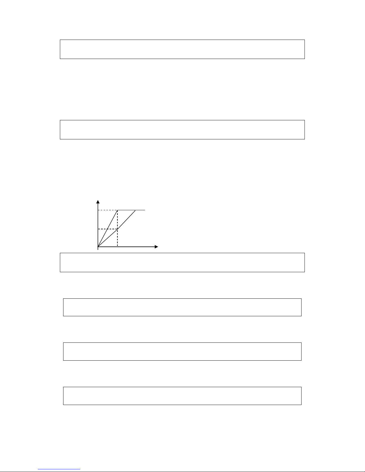
48
P100 Auto Torque Compensation
Set Range: 0.1~10.0% Unit: 0.1% Factory Setting: 2.0
This parameter can be set for the auto output of extra voltage when the inverter is running for higher
torque, which can compensate for the insuffcient torque at lower frequency. The torque compensation
should not be too big and it should be set slowly from low to high according to the actual situation.
Insufficient compensation will result in the insufficient torque of the motor at low frequency. And over
compensation will lead to too bigger torque, which will produce a shock to the machine and even
result in a trip of the inverter under serious situation.
P101 Auto Energy Saving
Set Range: 0.0~20.0% Unit: 1% Factory Setting: 0
When it is set to 0 this function is invalid. When Auto energy saving function is opened the
inverter will run at the full voltage during acceleration and deceleration. During the operationa at
constant speed the inverter can automatically calculate the optimum voltage value according to the
power of load to supply it to the load in order to meet the the goal of energy saving.
The output voltage can be regulated automatically and it can be decreaed by max.30% of normal
output voltage.
P102 PID Constant P
Set Range: 0.0~1000% Unit: 1 Factory Setting: 100
This proportional constant is set for the error value gain. If I=0, D=0, it is only for proportional
control.
P103 PID Constant I
Set Range: 0.1~3600 Unit: 1 Factory Setting: 5.0
The integral time (I) is set for the reaction speed for PID. The larger the I value is the slower the
reaction speed is. But if the integral time value is set too small, it will cause vibration.
P104 PID Constant D
Set Range: 0.01~10.0 Unit: 0.01 Factory Setting: 0
This didderential time (D) is set for the depression operation of PID. The larger the D value is,
the more obvious the depression operation is. When D is set to 0, it means this function invalid.
P105 PID Constant Target Value
Set Range: 0.0~100.0 Unit: 0.1 Factory Setting: 0.0
This target value can be set through external voltage signal or the digital operator.100% target
value is corresponding to the frequency quantity at +10V.
PID closed-loop control is usually used in the process control of no fast physical quantity
70%
F
100%
Output Voltage

49
changes, such as pressure control, temperature control, etc. The feedback signal is usually taken from
temperature, or pressure transmitter, etc. When under PID control, the feedback signal input path is
the analog current signal 4-20mA.
PID Control Block Diagram:
General operating methods of PID control:
⑴ Choose the correct transmitter (with the output specifcation of standard current signal 4-
20mA)
⑵ Set the right target value.
⑶ If the output doesn’ t have oscillation, increase the proportional constant (P);
⑷ If the output doesn’ t have oscillation, decrease the integral time (Ti);
⑸ If the output doesn’ t have oscillation, increase the differential time (Td).
-72-
PID closed-loop control is valid only when the multi-function inputs PID are open.
P106 PID Constant Target Value selection
Set Range: 0~1 Unit: 1 Factory Setting: 0
The selection of target value can be set through the selection of the panel or external analog
quantity. The external analog quantity is 0~10V signal or control of the potentiometer.
When P106=0, the target value of PID is set by P105.
M
P
Target value
I D VVVF
Transmitter
P102
Feedback
Before adjustment
Target value
After adjustment
Output
Time
1. Decrease the Over Output
a:Decrease the differential time (D)
b:Increase the integral time (I)
Input
Before adjustment
After adjustment
Target value
Time
2. Decrease the oscillation
a: Decrease the differential time (D)
b: Increase the integral time(P)

50
When P106=1, the target value of PID is set by external analog signal 0-10V (corresponding 0-
100%), the setting of P105 is invalid.
It should be noticed that in using PID control PID is only valid when P013 is set to 0.
P107 PID Upper Limit
Set Range: 0~100% Unit: 1 Factory Setting: 100%
When PID feedback value is more than the set value of P107 the corresponding multi-output
terminal will act and the machine will not stop.
P108 PID Lower Limit
Set Range: 0~100% Unit: 1 Factory Setting: 0
When PID feedback value is less than the set value of P108 the corresponding multi-output
terminal will act and the machine will not stop.
P109 Communication Addresses
Set Range: 00~250 Unit: 1 Factory Setting: 00
When the inverter is set to have RS-485 Communication interface control, each of the inverters
will be set for its individual identifcation number through P109.
00: No communication function
01~250: Individual identifcation number for the inverters
P110 Communication Band Rate
Set Range: 0~3 Unit: 1 Factory Setting: 1
0: 4800 b/s 1: 9600 b/s
2: 19200 b/s 3: 34800 b/s
P111 Communication Protocol
Set Range: 0~7 Unit: 1 Factory Setting: 1
0: 8N1 FOR ASCII 1: 8E1 FOR ASCII
2: 8O1 FOR ASCII 3: 8N1 FOR RTU
4: 8E1 FOR RTU 5: 8O1 FOR RTU
P120 Parameter lock
Set Range: 0~1 Unit: 1 Factory Setting: 0
0: Invalid. The parameter can be set.
1: Valid, i.e. parameter lock. Except this parameter and P000
This parameter can be used to prevent any wrong setting of other values by non maitenance persons.
P121 Display Contents
Set Range: 0~255 Unit: 1 Factory Setting: 00
Normally we can see directly output frequency, set frequency, output current, output voltage, but
temperatue, DC voltage, counter, PID feedback and revolution speed can only be monitored and
displayed in sequence through switching keys after the setting of P121.

51
Set the corresponding code for P121. For example: when asking for displaying the temperature and
revolution, then P121=2+16=18,just set P121to 18.
P122 Inverter Model Factory Setting: *
Factory Setting. It can be monitored, but not set.
P123 Inverter Rated Voltage Factory Setting: *
Factory Setting. Depending on the model. It can be monitored, but not set.
P124 Inverter Rated Current Factory Setting: *
Factory Setting. Depending on the model. It can’t be changed.
P125 Grid power frequency 50/60Hz
Set Range: 0~1 Factory Setting: 0
0: 50Hz
1: 60Hz
P126 Inverter manufacture date Factory Setting: ****
4 3 2
1
Week
Month
Year
P127 Manufacture Serial No. Factory Setting: *
Factory Setting. It can be monitored, but not set.
Through the manufacture serial number the manufavtury date, number as well as the information
about the inverter such as the numbers of main circuit board and base plate, etc. can be checked.
P128 Parameter & fault Reset
Set Range: 0~12 Unit: 1 Factory Setting: 0
0: Software Version No. 1~4: Fault record
6: Fault clear up 8: Restore factory settings
10: Input frequency at fault 11: Input current at fault
12: Bus voltage at fault
P129 Voltage Up Time during Frequency track
Set Range: 0.1~10.0S Unit: 0.1 Unit: 0.5
When frequency track is set, there is a process of voltage increase during the frequency track.
When the voltage is increasing rapidly the current will be high and the searching process will be
fast. When the voltage is up slowly the current will be low and the searching process will be slow.

52
P130 Stall & Decel Time during Running
Set Range: 0.1~25.5S Unit: 0.1S Factory Setting: 2.5S
Set the speed of frequency decrease for stall prevention at constant speed.
P131 Fault Reset Time
Set Range: 0.2~25.0S Unit: 0.1 Factory Setting: 1.0
When the inverter is set to fault restart and if theinverter has fault trip and the time exceeds the
setting of P131, the inverter will restart. Pay attention to the safety when using this function.
P132 Counter Memory for Power-off
Set Range: 0~1 Unit: 1 Factory Setting: 0
0: not memorized. 1: memorized.
P133 Drawing memory function
Set Range: 0~1 Unit: 1 Factory Setting: 0
0: not memorized. 1: memorized.
P134 Foced fan operation
Set Range: 0~1 Unit: 1 Factory Setting: 0
0: not forced. 1: forced.

53
Appendix 1: Function List
Parameter and Function List (Part 1)
Code
Function
Set Range
Factory
Setting
P000
Main Frequency
0.0~600.00 Hz
0.00
P001
Accel Time
0.1~6500.0S
5.0
P002
Decel Time
0.1~6500.0S
5.0
P003
V/F Curve
0~16
00
P004
Max. Output Voltage
0.1~255/510V
220/380
P005
Base Frequency
0.01~600.0 Hz
50/60
P006
Intermediate Voltage
0.1~255/510V
*
P007
Intermediate Frequency
0.01~600.00 Hz
*
P008
Min. Voltage
0.1V~*
*
P009
Min. Frequency
0.1~20.00 Hz
*
P010
Max. Frequency
10.00~600.00 Hz
50.00
P011
Frequency lower limit
0.00~600.00 Hz
0
P012
Operation command
source
0~2
0
P013
Operation Frequency
Source
0~2
0
P014
Starting mode
0~1
0
P015
Stopping Mode
0~1
0
P016
Rev rotation selection
0~1
1
P017
STOP key selection
0~1
1
P018
S-curve time
0~6500S
0
P019
Carrier frequency
0~15
9
P020
Starting frequency
0.1~10.0 Hz
0.5
P021
Stopping frequency
0.1~10.0 Hz
0.5
P022
Jog Frequency
0.00~600.00 Hz
5.00
P023
Jog Accel/Decel Time
0.1~25S
1.0
P024
PLC operation
0~5
0
P025
Auto PLC operation
(internal multi-speed)
0~3
0

54
Parameter and Function List (Part 2)
Code
Function
Set Range & Function
Explanation
FactorySetting
P026
PLC rotation Direction
0~255
0
P027
PLC accel/decel time 1
0~255
0
P028
PLC accel/decel time 2
0~255
0
P029
Accel Time 2
0.1~6500.0S
16
P030
Decel Time 2
0.1~6500.0S
16
P031
Accel Time 3
0.1~6500.0S
32
P032
Decel Time3
0.1~6500.0S
32
P033
Accel Time 4
0.1~6500.0S
64
P034
Decel Time 4
0.1~6500.0S
64
P035
Frequency 2
0.00~600.00 Hz
15.00
P036
Frequency 3
0.00~600.00 Hz
20.00
P037
Frequency 4
0.00~600.00 Hz
25.00
P038
Frequency 5
0.00~600.00 Hz
30.00
P039
Frequency 6
0.00~600.00 Hz
35.00
P040
Frequency 7
0.00~600.00 Hz
40.00
P041
Frequency 8
0.00~600.00 Hz
0.50
P042
PLC Timer 1
0.0~6500.0S
10.0
P043
PLC Timer 2
0.0~6500.0S
10.0
P044
PLC Timer 3
0.0~6500.0S
0.0
P045
PLC Timer 4
0.0~6500.0S
0.0
P046
PLC Timer 5
0.0~6500.0S
0.0
P047
PLC Timer 6
0.0~6500.0S
0.0
P048
PLC Timer 7
0.0~6500.0S
0.0
P049
PLC Timer 8
0.0~6500.0S
0.0

55
Parameter and Function List (Part 3)
Code
Function
Set Range & Function
Explanation
FactorySetting
P050
Multi-input FWR
0: Inval id; 1: Run; 3: For.
rotation; 4: Rev.rotation; 5:
For/Rev.; 6: Jog; 7: Jog For
rotation; 8: Jog Rev Rotation;
9: Emergency stop; 10: Reset ;
12: Overheat of radiator or motor;
13: Timer 1start; 14: Timer 2
start; 17: High speed ; 18:
middle speed; 19: Low speed;
20: Multi-Speed 1; 21: Multi-
Speed 2; 22: Multi-Speed 3;
23: Accel/Decel select 1; 24:
Accel /Decel select 2; 25: UP
function ; DOWN function; 27:
Counter ; 28: Counter reset;
29: Drawing start; 31: AutoPLC
Reset suspend; 32: PID valid
02
P051
Multi-input REV
03
P052
Multi-input RST
10
P053
Multi-input SPH
17
P054
Multi-input SPM
18
P055
Multi-input SPL
19

56
Parameter and Function List (Part 4)
Code
Function
Set Range & Function
Explanation
FactorySetting
P056
Multi-input DRV
0: Invalid; 1: Run; 2: Fault
Signal ; 3: Zero Speed;
4: DC Braking indication ;
5 : Set Frequency reach;
6: Random Frequency 1 reach;
7: Random Frequency 2 reach;
8: In Accel.; 9: In Decel.;
10: Inverter Overload alarm;
11: Motor Over load alarm;
12: Over torque detect;
13: Undervoltage alarm ;
14 : Single stage end;
15: Process end;
16: Set Counter reach;
17: Intermediate Counter reach ;
18: Externally controlled Timer 1
reach ; 19 : Externally controlled
Timer 2 reach ; 20 4~20mA
disconnected; 27:Drawing reach ;
28: PID Down Limit alarm; 29:
PID Up Limit alarm; 30: Fan
run; 31: Electromagnetic Relay
act; 32: Braking Resistor act
01
P057
Multi-input FABC
05
P058
Multi output AM
0~7
0
P059
AM Analog Output Gain
0.0~100.0%
100
P060
UP-DOWN mode
0~1
0
P061
Reserved
P062
Timer 1 time
0.0~10S
00.0
P063
Timer 2 time
0~100S
000
P064
Counter
0~9999
00
P065
Intermediate Counter
0~9999
0
P066
Skip Frequency 1
0.00~600.00 Hz
0.00
P067
Skip Frequency 2
0.00~600.00 Hz
0.00

57
Parameter and Function List (Part 5)
Code
Function
Set Range & Function
Explanation
FactorySetting
P068
Skip Frequency 3
0.00~600.00 Hz
0.00
P069
Skip Frequency Range
0.1~10.00 Hz
0.5
P070
Random frequency 1
0.00~600.00 Hz
0.00
P071
Random frequency 2
0.00~600.00 Hz
0.00
P072
Analog input select
0~4
0
P073
Analog Low End Frequency
0.00~600.00 Hz
0
P074
Bias Direction at Lower Frequency
0~1
0
P075
Analog High End Frequency
0.00~600.00 Hz
50.00
P076
Bias direction of high end frequency
0~1
0
P077
Analog negative bias reverse
0~1
0
P078
Analog Filtering Constant
0~50
20
P079
Overvoltage stall prevention
0~1
0
P080
Stall prevention level during accel.
0~200%
150
P081
Stall prevention level during running
0~200%
0
P082
Stall prevention level during decel.
0~200%
150
P083
Overtorque detect level
0~200%
0
P084
Overtorque detect time
0.1~20.0S
1.0
P085
Rated motor voltage
*
*
P086
Rated motor current
*
*
P087
Motor poles
02~60
04
P088
Rated motor revolution
0~9999r/min
1440
P089
Motor no-load current
0~100%
40
P090
Slip compensation
0~1.0
0.000
P091
DC braking voltage
0.0~20.0
2.0
P092
DC brake time at starting
0.0~25.0S
0.0
P093
DC brake time at stopping
0.0~25.0S
0.0
P094
Frequency track time
0.0~20.0S
5.0
P095
Frequency track current level
0~200%
150
P096
Restart after instantanuous stop
0~1
0

58
Parameter and Function List (Part 6)
Code
Function
Set Range & Function
Explanation
FactorySetting
P097
Allowable power off time
0.1~5.0S
0.5
P098
Number of abnormal restart
0~10
00
P099
Auto voltage regulation function
0~1
1
P100
Auto torque compensation
0.0~10.0%
2.0
P101
Auto energy savings
0~20.0%
0.0
P102
PID parameter P value
0~1000%
100
P103
PID parameter I value
0~3600S
5.0
P104
PID parameter D value
0.01~10.00S
0
P105
PID parameter target value
0.0~100.0%
0
P106
PID parameter target value selection
0~1
0
P107
PID Upper Limit
0~100%
100
P108
PID Lower Limit
0~100%
0
P109
Communication address
0~250
1
P110
Communication band rate
0~3
1
P111
Communication protocol
0~5
3
P112~
P119
Reserved
P120
Parameter lock
0~1
0
P121
Display content
0~255
00
P122
Inverter model
*
*
P123
Inverter Rated Voltage
Depending on type
*
P124
Inverter Rated Current
Depending on type
*
P125
Grid power frequency
0: 50Hz 1: 60Hz
0
P126
Inverter manufacture date
Factory Setting
*
P127
Manufacture Serial No.
*
P128
Parameter & fault Reset
00~12
00
P129
Voltage up time during Frequency
track
0.1~10.0S
0.5
P130
Stall & decel time during running
0.1~25.5S
2.5
P131
Fault reset time
0.2~25.0S
1.0
P132
Counter memery for power-off
0~1
0
P133
Drawing memory function
0~1
0
P134
Forced fan operation
0~1
0

59
Appendix 2: Installation Dimensions
Series
External Appearance and Installation Dimensions
DLM1-
0D40S2G
DLM1-
0D75S2G
DLM1-
01D5S2G
Digital
operator
单位: mm
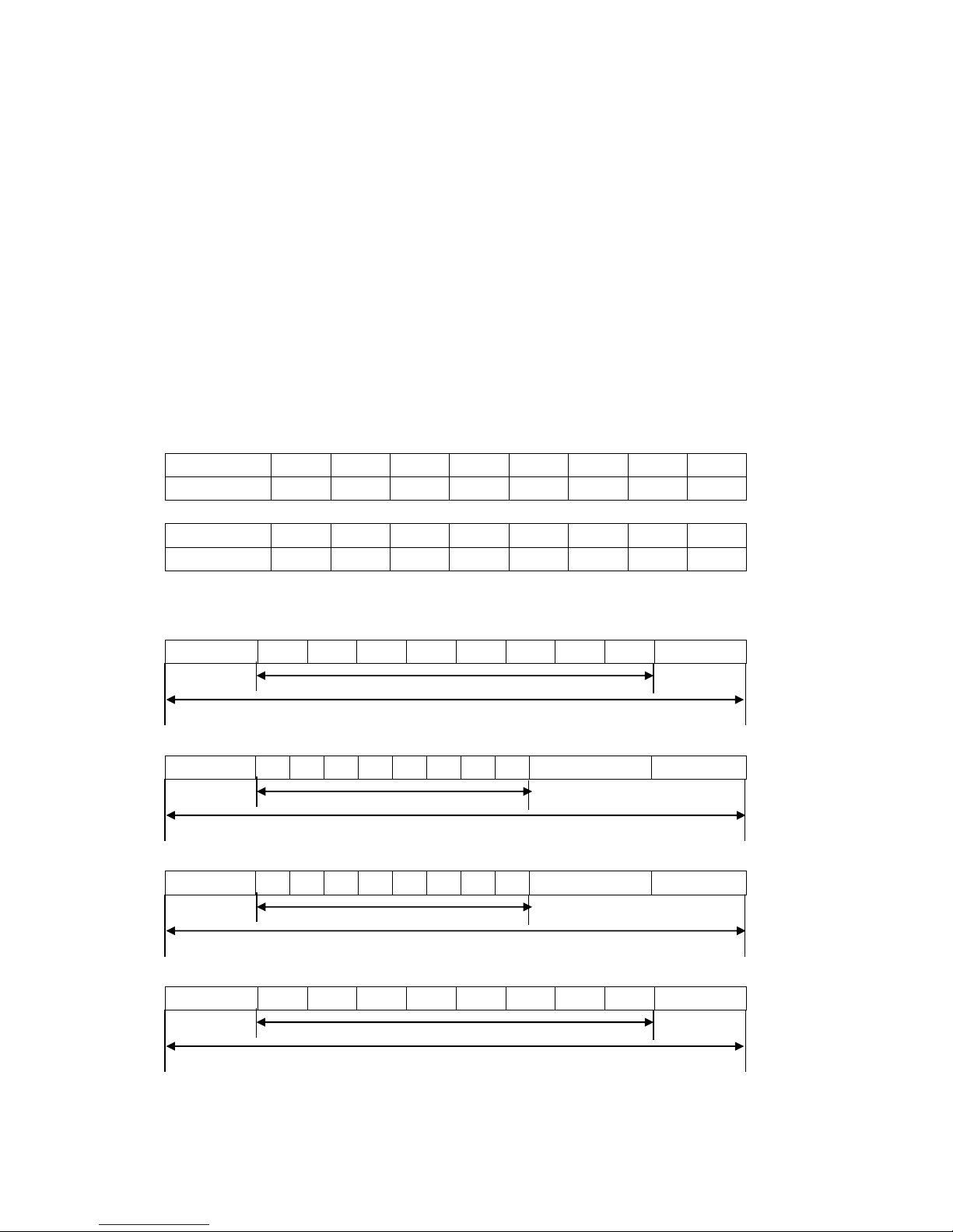
60
Appendix 3: MODBUS Communication Protocol
When using the RS485 communication interface, each of the inverters must set its own address
so that the computer can use this individual address to carry out the control.
1: Communication port terminal setting
The communication protocol
has two modes: RS485Communication Port
⑴ RTU mode (Remote Terminal Unit)
⑵ASCII mode(American Standand Code for imformation interchange)
Information of code.
RTU mode: Each of 8-bit data is composed of two 4-bit (hexadecimal), for example: 64H
ASCII mode: Each of 8-bit data is composed of two ASCⅡbyte, for example:
One 1-bit data 64H (hexadecimal) is composed of ASCⅡ byte“64”, included“6”(36H) and
“4”(34H).
Byte
0 1 2 3 4 5 6 7 ASCII Code
30H
31H
32H
33H
34H
35H
36H
37H Byte
8 9 A B C D E F ASCII Code
38H
39H
41H
42H
43H
44H
45H
46H
2: Communication Data Method
(1)8N1 For ASCII P111=0
Start bit
0 1 2 3 4 5 6 7 Stop bit
(2)8E1 For ASCII P111=1
Start bit
0 1 2 3 4 5 6 7 Even parity
Stop bit
(3)8O1 For ASCII P111=2
Start bit
0 1 2 3 4 5 6 7 Odd parity
Stop bit
(4)8N1 For RTU P111=3
Start bit
0 1 2 3 4 5 6 7 Stop bit
(5)8E1 For RTU P111=4
8-Data bits Bit string
10- bits Charator frame
8-Data bits Bit string
11- bits Charator frame
8-Data bits Bit string
10- bits Charator frame
8-Data bits Bit string
11- bits Charator frame
61
Start bit
0 1 2 3 4 5 6 7 Even parity
Stop bit
(6)8O1 For RTU P111=5
Start bit
0 1 2 3 4 5 6 7 Odd parity
Stop bit
3: Communication Document Formats
3.1 ASCII Mode
Communication Document Forms
STX
“: ”
(3AH)
ADDR
FUNC
LEN
DATA
(n-1)
。。。
DATA0
CRC
END
CR(0DH)
LF(0AH)
⑴ STX: Starting unit“: ”(3AH)
⑵ ADDR communication address,8-bit data is composed of two
ASCⅡ byte.
00: Broadcast mode is MODBUS
01~250: the addresses of corresponding inverters.
⑶ FUNC: Function code 8-bit data is composed of two ASC Ⅱ
byte.
01: FUNC READ, Read the data of function code
02: FUNC WRIT, write the data of function code
03: write control data
04: read control status data
05: write inverter frequency data
06: Reserved
07: Reserved
08: Loop test
a: Read function code data
format:
ADDR 01 LEN FUNC Data
ADDR=0 means no answer
ADDR≠0 means a reply from inverter of this address
When inverter reply normal, the format as follows:
ADDR 01 LEN FUNC Data
If DATA is one word, the LEN=3, If DATA is one byte, the LEN=2 .
When inverter has no this function code or reply no effect, the format as follows:
ADDR 81H 01 FUNC
b: Write function code data
Format:
8-Data bits bits Bit string
11- bits Charator frame
8-Data bits bits Bit string
11- bits Charator frame

62
ADDR 02 LEN FUNC Data
ADDR=0 for broadcast, it write to all inverter, but no reply.
ADDR≠0, set data and reply from inverter of this address.
When inverter has no this function code or reply of no effect, the
format as follows:
ADDR 81H 01 FUNC
c: Control commands
Format:
ADDR 03 LEN CNTR
ADDR=0 for broadcast, it write to all inverter, but no reply
ADDR≠0, reply and return.
CNTR
7 6 5 4 3 2 1 0 jogr
jogf
jog
r/f
stop
rev
for
run
When the setting is correct return to present control status.
Format: ADDR 03 LEN CNST
CNST
7
6 5 4 3 2 1 0
Search start
Braking
r/f
joging
running
r/f
jog
run
When check is not correct,
ADDR 83H 01 CNST
d: Read status value
Format:
ADDR 04 01 CFG
ADDR=0, no reply
ADDR≠0, reply.
CFG=0~7, reply single data
0: Set F 1: Out F 2: Out A 3: RoTT
4: DCV 5: ACV 6: Cout 7: Tmp
For example: read set frequency
Send: 01 04 03 00 41 89
Return: 01 04 03 13 88 89 A6 2D
13 88 are data
13 is high order, 88 is low order.
⑷ LEN: data length, It means the length of D(n-1)…D0,
Length set: when one word, LEN=3, when one byte or <1byte, LEN=2。
⑸ DATA: <Data characters> data content. 2n ASCII composen bytes, it have ffty ASCⅡ at most.
⑹ LRC: longitudinal redundancy check
ASCII mode: Get LRC methods is that add ADDR to the last data, if the result is more than 256,then
the result subtract 256 until the result is less then 256 (if the result is 128H, take 28H), then
100H subtract the result get LRC.
⑺ For example: write 30.00Hz to inverter of 01(write to P000)
STX
ADDR
FUNC
LEN
DATA
LRC
END

63
“: ”
“0”
“1”
“0”
“2”
“0”
“2”
“0”“0”“0”
“B”“HB”“8”
“3”
“7”
“CR”
“LF”
3AH
30H
31H
30H
32H
30H
33H
30H 30H 30H
42H 42H 38H
33H
37H
0DH
0AH
Calculate LRC: 01H+02H+03H+00H+0BH+B8H=C9H
C9H subtracted from 100H: 37H
So the sent data is following:
3AH 30H 31H 30H 32H 30H 33H 30H 30H 30H 42H 42H 38H 33H 37H 0DH 0AH
3.2 RTU Mode
Quiet
ADDR
FUNC
LEN
D(n-1)~D(0)
CRC
Quiet
>50ms
>50ms
⑴ Quiet: the time of no data is more than 50 ms
⑵ ADDR: Communication address, 8-bit data
⑶ FUNC: Function code, 8-bit data, refers to 3.1-3
⑷ LEN: Data length, the length of D(n-1)~D0
⑸ DATA: data content, n*8-bit
⑹ LRC: Longitudinal Redundancy Check
RTU mode: get CRC(cyclical Redundancy Check).
The CRC calculation method is following:
⑴ make a 16-bit register and set value 0FFFFH(call CRC register)
⑵ done frst byte of data Exclusive OR with low byte of 16-bit CRC register and save the
result to CRC register
⑶ done 1 bit right shift with CRC register and fll zero to left bit, then check low bit of CRC
register.
⑷ if the low bit is zero, then do repeat setp3, else CRC register do Exclusive OR with
0A001H.
⑸ done repeat step 3 and 4,until CRC register done right shift 8 times,then the byte is fully
done.
⑹done repeat step 2 to 5 for the next byte of data, until process completely all data. The last
data of CRC register is CRC value.
When send CRC value in command data, low bytes must change the sequence with high
bytes, i.e. low bytes will be sent frst.
⑺for example 1: Write 30.00Hz to inverter of 01
Command data
ADDR
FUNC
LEN
DATA
CRC
01H
02H
03H
00H 0BH B8H
7FH 0CH
Sent data: 01H 02H 03H 00H 0BH B8H 7FH 0CH
⑻ for example 2:
The following is that get CRC value with C language. The function has two parameters:
Unsigned char data ← the point of data buffer
Unsigned char lengh ← number of data buffer
This function will send back the CRC value with unsigned integer format.
unsigned int crc_chk(unsigned char data,unsigned char lengh)
{

64
int j;
unsigned int reg_crc=0xffff;
while (lengh--){
reg_crc^=*data=++;
for(j=0; j<8; j++={
if(reg_crc&0×01){/*LSB(b0)=1*/
reg_crc=(reg_crc>>1)^0xa001;
}else{
reg_crc=reg_crc>>1;
}
}
}
return reg_crc;
}
 Loading...