

DORNA TECHNOLOGY DLA1 Series, DLA1-0D75S2G, DLA1-0D40S2G, DLA1-01D5T4G, DLA1-0D75T4G User Manual
...
DORNA TECHNOLOGY CO., LTD
DLA1 Series Inverter
User Manual (V2.0)

2
Table of Contents
1 Summary ....................................................................................................... 4
1.1 Name plate .......................................................................................................... 4
1.2 Product series ...................................................................................................... 5
1.3 Technical standards ............................................................................................. 6
1.4 Peripheral Electrical Devices and System Configuration ..................................... 8
1.5 Product outline and installation dimensions ....................................................... 9
1.5.1 Product outlines (unit: mm) ................................................................................... 9
1.5.2 Production dimension table ................................................................................. 10
2 Wirings ........................................................................................................ 11
2.1 Standard wiring diagrams .................................................................................. 11
2.2 Main circuit wirings ........................................................................................... 12
2.3 Control circuit wirings ........................................................................................ 13
2.3.1 Control circuit signals ........................................................................................... 13
2.3.2 Control circuit wiring notes .................................................................................. 14
2.3.3 Control circuit jumpers ......................................................................................... 15
3 Panel operations ...................................................................................... 16
3.1 Keyboard interface ............................................................................................ 16
3.2 Parameter setting example ............................................................................... 17
3.3 Motor parameter auto-tuning ........................................................................... 17
3.4 JOG run .............................................................................................................. 18
4 Function codes (Parameters) .................................................................... 19
4.1 Monitoring parameters: d0.00-d0.65 ................................................................ 19
4.2 Basic functions group: P0.00-P0.28 ................................................................... 22
4.3 First motor parameters: P1.00-P1.37 ................................................................ 29
4.4 Vector control parameters: P3.00-P3.22 ........................................................... 31
4.5 V/F control parameters: P2.00-P2.27 ................................................................ 31
4.6 Input terminals: P4.00-P4.39 ............................................................................. 37
4.7 Output terminals: P5.00-P5.22 .......................................................................... 46
4.8 Start/stop control: P6.00-P6.15 ......................................................................... 50
4.9 Keyboard and display: P7.00-P7.14 ................................................................... 54
4.10 Auxiliary functions: P8.00-P8.54 ...................................................................... 57
4.11 Fault and protection: P9.00-P9.73 ................................................................... 64
4.12 PID functions: PA.00-PA.28 .............................................................................. 74
4.13 Swing Frequency, Fixed Length and Count: PB.00-PB.09 ................................ 78
4.14 Multi-speed and simple PLC: PC.00-PC.51 ....................................................... 80
4.15 Communication parameters: PD.00-PD.06 ...................................................... 84
4.16 Function code management: PP.00-PP.04....................................................... 85
4.17 Torque control parameters: B0.00-B0.08 ........................................................ 86
4.18 Control optimization parameters: B5.00-B5.09 ............................................... 87
5 Fault and solutions ...................................................................................... 89
5.1 Alarms and solutions ......................................................................................... 89

3
5.2 Other fault and solutions ................................................................................... 94
6 Repair and maintenance ............................................................................. 96
6.1 Routine maintenance ........................................................................................ 96
6.2 Replacement of vulnerable components ........................................................... 96
7 MODBUS communication protocol .............................................................. 97
7.1 Communication protocol ................................................................................... 97
7.2 Verification mode ............................................................................................ 100
7.3 Communication addresses .............................................................................. 101
Appendix I: Brake accessories ...................................................................... 105

Safety Precautions
Please pay close attention to all safety-related information in this user manual; otherwise there may be
fatal consequences. Please note the manufacturer shall bear no liabilities to damages of any sorts
resulting from false operations which is not following this user manual.
Warning ---- potential risks. Fatality may be caused if not avoided.
Attentions – please follow these instructions when using the inverter.
Do not do wiring operations at power on;
Only qualified electrical engineers can install & maintain the inverter;
Power on the inverter only after the covers have been put back on. Do not remove the cover during
power on;
Please wait at least 10 minutes after power of to remove the cover; so as to let DC bus capacitors to
fully discharge;
Please make sure the rated input voltage is compatible with the power supply voltage. Otherwise, there
may be risks of fire;
Please do not operate the inverter with wet hands. The inverter has many semiconductor components
inside;
The inverter is not designed for voltage-withstanding tests;
Do not alter the inverter;
Do not install or use any inverter which is already broken or with faulty parts.
Attentions – when scrapping the inverter.
Electrolytic capacitors on the PCBs of the inverters may explode if incinerated;
Poisonous gas may emit if incinerated;
Please dispose scrapped inverters as industrial waste.
WARNING
Risk of electric shock!
Wait at least 10 minutes after power off to remove the cover.
Read the user manual and follow the safety instructions before use.
A

-2-
Quick installation guide
Flowchart for installation & maintenance:
Tasks
Main circuit wiring.
Control circuit wiring.
Inverter JOG run.
Chapter 5
Chapter 3.3
Chapter 2.6
Chapter 2.5
References
Get familiar with panel
operations.
Chapter 3
Check installations
Chapter 2.4
Remove the packaging and
check inverter model.
Check environment and input/
output cables.
Confirm inverter capacity is
compatible with motor.
Fault & solutions
Chapter 1
B

-3-
Attention: please follow inverter installation location requirements strictly.
Environmental requirements for installation of inverters:
Temperature
-10°C to +40°C (derate 1% for every °C if the ambient temperature is between
40°C and 50°C)
Altitude
Less than 1000m (derate 10% for every 1000m if the altitude is above 1000m)
Other
requirements
Please install the inverter in a place which is not inclining to fierce shocks
or vibrations. Maximum vibration is 5.8m/s
2
(0.6g);
Please install the inverter in a place which is far from electromagnetic
radiations;
Please install the inverter in a place where metal dust, normal dust, oil, or
water is hard to enter inside the inverter;
Please do not install the inverter in a place which is exposed to direct
sunlight, with combustible gas, oil smoke, vapor, drip or salt;
Humidity should be Less than 90%RH, without condensing.
Spacing for inverter installations:

-4-
1 Summary
1.1 Name plate
Model
Power
Input power
Output
MODEL: DLA1-02D2T4G
POWER : 2.2kW
INPUT: AC3PH 380V 50Hz/60Hz 6A
OUTPUT: AC3PH 0~380V 0~30 0Hz 5A
S/N:
Dorna Technology CO.,ltd
Barcode
T:Three phase
S:Single phase
Inverter series
DLA 1-0D75 T 4 G
Inverter capacity
G: general-purpose
P: Light load
Rated input voltage:
2:220V 4:380V
7:660V/690V
Plant code
【1】
【2】
【3】
【6】
【5】
【4】

-5-
1.2 Product series
Inverter model
Rated output
power (kW)
Rated input current
(A)
Rated output
current (A)
Single Phase input: AC 220V -15%~+10%, 50/60Hz
DLA1-0D40S2G
0.4
5.9
2.5
DLA1-0D75S2G
0.75
8.3
4
DLA1-01D5S2G
1.5
14.1
7
DLA1-02D2S2G
2.2
11.8
10
Three phase input: AC 380V -15%~+10%, 50/60Hz
DLA1-0D75T4G
0.75
4.3
2.5
DLA1-01D5T4G
1.5
5.2
3.7
DLA1-02D2T4G
2.2
6.0
5
DLA1-0004T4G
4.0
10.5
8.5
DLA1-05D5T4G
5.5
15.5
13

-6-
1.3 Technical standards
Item
Specifications
Basic functions
Control system
Current Vector General Purpose Inverter.
Compatible motor
Induction motors.
Maximum
frequency
Vector control: 0~500Hz;
V/F control: 0~500Hz.
Carrier frequency
0.8kHz~12kHz; Depending on load, can automatically adjust.
Input resolution
Digital: 0.01Hz;
Analog: maximum frequency×0.025%.
Control modes
Open vector control (SVC);
V/F (scalar) control.
Starting torque
G type: 0.5Hz/150% (SVC); 0Hz/180% (FVC).
P type: 0.5Hz/100%.
Speed range
1: 100 (SVC)
1: 1000 (FVC)
Speed accuracy
±0.5% (SVC)
±0.02% (FVC)
Torque accuracy
±5% (FVC)
Overload capacity
G type: 150% rated current 60s; 180% rated current 3s;
P type: 120% rated current 60s; 150% rated current 3s.
Torque boost
Automatic
Manual 0.1%~30.0%
V/F curve
Straight-line V/F curve
Multi-point V/F curve
N-power V/F curve (2-power, 1.4-power, 1.6-power, 1.8-
power, 2-power square)
V/F separation
Two types: complete separation; half separation. AVR output.
Ramp mode
Straight-line ramp
S-curve ramp
Four groups of acceleration/deceleration time: 0.0–6500.0s
DC braking
DC braking frequency: 0.00 Hz to maximum frequency
Braking time: 0.0–36.0s
Braking action current value: 0.0%–100.0%
JOG control
JOG frequency range: 0.00–50.00 Hz
JOG acceleration/deceleration time: 0.0–6500.0s
Simple PLC
Up to 16 speeds via the simple PLC function or DI terminals
Onboard PID
Process-controlled closed loop control system
Auto voltage
regulation (VR)
Keep constant output voltage automatically when grid voltage
fluctuates.
Overvoltage/
Overcurrent stall
control
The current and voltage are limited automatically during the running
process so as to avoid frequent tripping due to
overvoltage/overcurrent.
Fast current limit
function
Protect inverter from overcurrent malfunctions.
Torque limit and
control
It can limit the torque automatically and prevent frequent over
current tripping during the running process. Torque control can be
implemented in the FVC mode.
Power dip ride
through
The regenerative energy from load compensates the voltage
reduction so that the inverter can continue to run for a short time.
Timing control
Time range: 0.0–6500.0 minutes

-7-
Two-motor
switchover
Two motors can be switched over via two groups of motor
parameters.
Fieldbuses
RS485
Operations
Command source
Keyboard
Control terminals
Serial communication port
You can perform switchover between these sources in various ways.
Frequency source
10 frequency sources, such as digital setting, analog voltage setting,
analog current setting, pulse setting and serial communication port
setting. You can perform switchover between these sources in
various ways.
Auxiliary
frequency source
10 auxiliary frequency sources. It can implement fine tuning of
auxiliary frequency and frequency synthesis.
Input terminal
5 digital input (DI) terminals;
2 analog input (AI) terminals which support 0–10V voltage input or
0–20mA current input.
Output terminal
1 digital output (DO) terminal;
1 relay output terminal;
1 analog output (AO) terminals which support 0–20mA current
output or 0–10V voltage.
Display and
Key lock
It can lock the keys partially or completely and define the function
range of some keys so as to prevent misconducts.
Protection
functions
Motor short-circuit detection at power-on, input/output phase loss
protection, overcurrent protection, overvoltage protection, under
voltage protection, overheat protection and overload protection
Environment
Location
Indoor, free from direct sunlight, dust, corrosive gas, combustible
gas, oil smoke, vapor, drip or salt.
Altitude
Less than 1000m.
Ambient
temperature
-10°C to +40°C (de-rated if the ambient temperature is between
40°C and 50°C)
Humidity
Less than 90%RH, without condensing
Vibration
Less than 5.8m/s
2
(0.6g).
Storage
temperature
-20℃~+60℃.

-8-
1.4 Peripheral Electrical Devices and System Configuration
Grounding
Circuit
braker
Motor
DC reactor
EMC
filter
Grounding
AC
reactor
Inverter
EMC
filter
Contactor
AC reactor
Power
Brake
resistor
Brake
unit
-9-
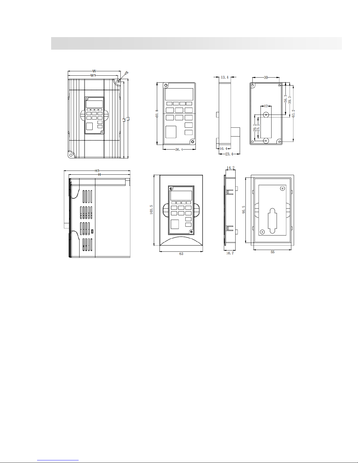
1.5 Product outline and installation dimensions
1.5.1 Product outlines (unit: mm)

-10-
1.5.2 Production dimension table
Model
Dimensions
Holes
(mm)
Net
(Kg)
Gross
(Kg)
L2
(mm)
L3
(mm)
W
(mm)
W1
(mm)
H
(mm)
H1
(mm)
DLA1-0D40S2G
DLA1-0D75S2G
DLA1-01D5S2G
136.5
142
85
79.5
112.5
122.5
M5
DLA1-0D75T4G
DLA1-01D5T4P
145.5
151
100
94.5
116.5
126.5
M5
DLA1-01D5T4G
DLA1-02D2T4P
DLA1-02D2T4G
DLA1-03D7T4P
DLA1-03D7T4G
DLA1-05D5T4P
DLA1-05D5T4G
DLA1-07D5T4P

-11-
2 Wirings
2.1 Standard wiring diagrams
M
3~
U
W
V
P+P-
R
S
T
Input power
PB
Brake resistor
TA1
TB1
TC1
+24
V
DI1
DI2
DI3
DI4
DI6
COM
P4.00=1 FWD
P4.01=4 FJOG
P4.02=9 RESET
P4.03=12 Speed 1
P4.05=2 REV
NPN (default)
GND
AI1
+10V
PE
VR
1K
2W
Default: 0-10V input
GND
AI2
+10V
PE
VR
1K
2W
GND
Motor
Main circuit
Control circuit
DO1
COM
AO
1
GND
P
E
P5.07=0
0-10V Max load current: 5mA
0-20mA Max load resistance: 250Ω
Circuit
breaker
RS485
GND
P
E
RS+
RS-
Shielding
DLA1
-12-
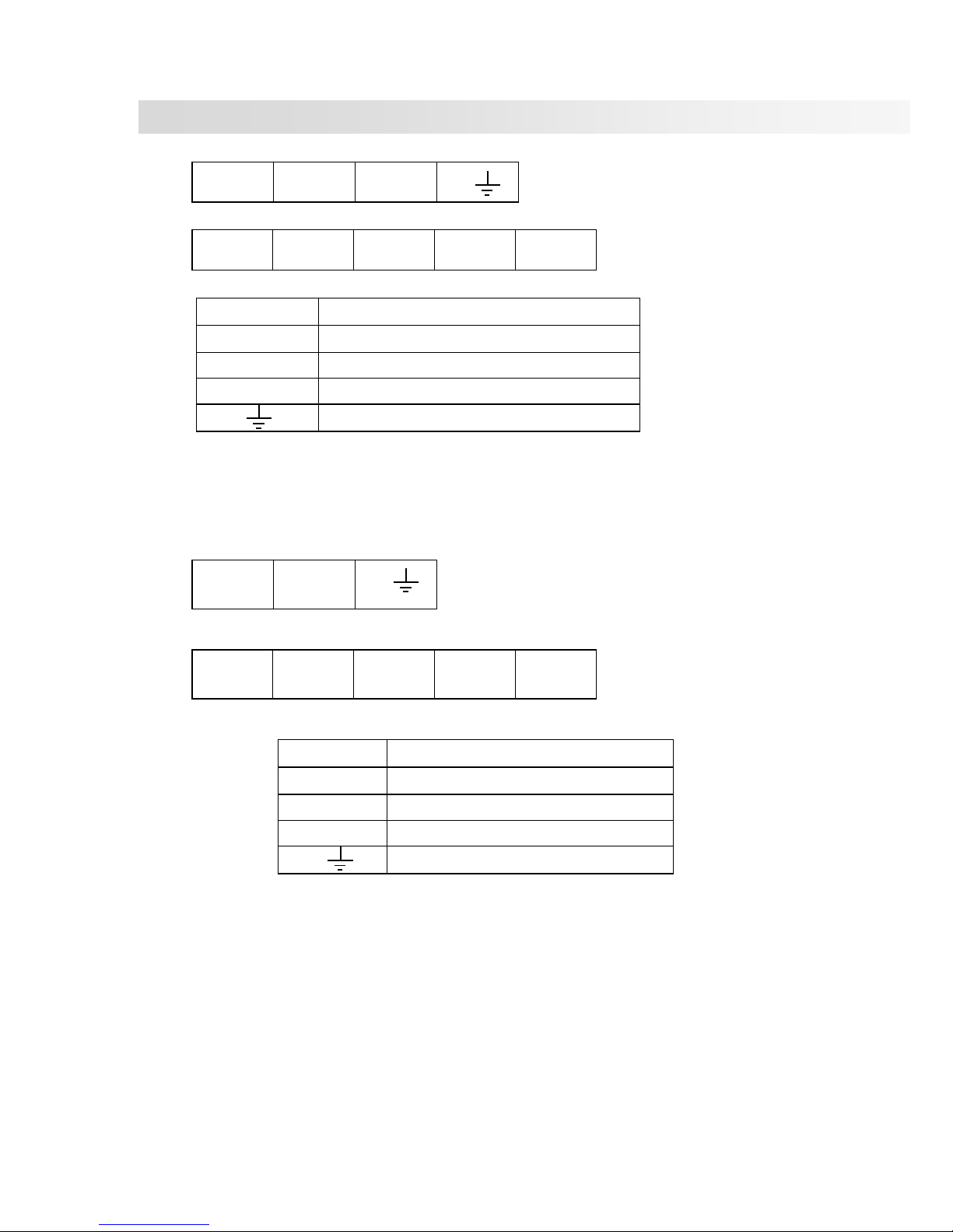
2.2 Main circuit wirings
380V class:
R S T
U V W
P+
PB
Terminals
Functions
R、S、T
Input power
P+、PB
External brake resistor
U、V、W
Output power
GND
220V class
L1
L2
PB
P+ U V
W
Terminals
Functions
L1、L2
Input power
P+、PB
External brake resistor
U、V、W
Output power
GND
-13-
2.3 Control circuit wirings
2.3.1 Control circuit signals
TC1
TB1
TA1
AGND
AI1
AI2
AO1
+10V
COM
DO1
DI1
DI2
DI3
DI4
DI6
Type
Terminal
Name
Function
Specifications
Input
Digital
DI1
Input terminal X1
Default: Forward run (FWD)
Opti-coupler
insulation
DC24V/8mA
External power
voltage range: 9~
30V. DI5 pulse
input range: 0~
100kHz.
DI2
Input terminal X2
Default: Forward JOG (FJOG)
DI3
Input terminal X3
Default: Fault reset (RESET)
DI4
Input terminal X4
Default: Multi-speed terminal 1
DI6
Input terminal X6
Default: Reverse run (REV)
SP
Input terminal
common
Default: +24V short-circuit
with SP by Jumper J9
Analog
10V
Analog 10V
Power
Output capacity: 10mA or
below, 1kΩ~5kΩ
0~20mA input:
input impedance is
500 ohms.
0~10V input:
input impedance is
20K ohms.
AI1
Analog setting 1
Default: 0~10V
(resolution1/1000)
AI2
Analog setting 2
Default: 0~20mA
(resolution1/1000)
AGND
Analog common
0V
Output
Relay
TA1
A node output
Default setting: stop fault
during operation
TA1—TC1: normally open
TB1—TC1: normally close
Node capacity:
AC250V, 3A.
TB1
B node output
TC1
Node output
common terminal
Digital
DO1
Open collector
output 1
Default: inverter in operation
Below DC24V,
50mA.
COM
Digital common
Analog
AO1
Analog monitor
output 1
Voltage or current output;
Default: output frequency
Output voltage
range: 0~10V;
Output current
range: 0~20mA.
AGND
Analog common
0V

-14-
2.3.2 Control circuit wiring notes
Analog input wirings
As analog signals can be easily affected by external interference, shielded cables shall be used. Cables
shall be as short as possible and not exceeding 20 meters. As shown in graphs below, in some severe
circumstances, filter capacitor or ferrite bread shall be used in analog signal side.
Digital input wirings
Shielded cables shall be used. Cables shall be as short as possible and not exceeding 20 meters. When
using active drive mode, user shall take necessary filter measures to counter power interference. It is
recommended to use node control mode. Digital inputs can be NPN or PNP.
NPN input: Most common. Use
internal 24V power; +24V terminal shortcircuit with SP terminal; COM terminal
is common; J9 is 23 jumped; also known
as drain wiring mode.
PE
+10V
GND
AI1
DLA1
Potentiometer
Less than 20m
DLA1
AI1
GND
0.022uF
50V
Ferrite bread
External
analog
source
NPN
信号
COM
4.7K
4.7K
D15
D11
SP
+24V
0V
+24V
+VCC
3.3Ω
External
controller
Inverter

-15-
PNP input: Use external 24V power;
external power negative node is
connected with SP terminal; external
terminal positive node is common;
external power voltage range is 9~30V;
J9 is 12 jumped; also known as source
wiring mode.
Output wirings
Digital output is open collector output. When using external power, please connect external power
negative node to COM terminal. Maximum current is 50mA for open collector output. If external load is
relay, please install fly-wheel diode to both ends of the relay.
Note: please install fly-wheel diode
polar correctly, otherwise internal
components will be damaged.
2.3.3 Control circuit jumpers
J5: RS485 matching resistor selection J1: AO1 output selection
Not use
Use 120
resistor
1
2
3
1
2
3
0-10V
0-20mA
1
2
3
1
2
3
PNP
信号
COM
4.7K
4.7K
D15
D11
SP
+24V
0V
+24V
+VCC
3.3Ω
External
controller
Inverter
9-30V
Relay
Fly-wheel
diode
+24V
DO1
DO2
CME
Max current: 50mA
Inverter
COM

-16-
3 Panel operations
3.1 Keyboard interface
Keyboard outline is as below:
Keys/Lights
Function
Descriptions
DIR (light)
Rotating direction
status
ON: FWD
OFF: REV
RUN (light)
Operation status
ON: RUN
OFF: STOP
LOCAL (light)
Command source
status
ON: terminal control
OFF: keyboard control
BLINK: remote (communicational) control
TUNE/TC (light)
Tune/fault
ON: in torque control mode
SLOW BLINK: in tuning status
FAST BLINK: in fault status
Hz A V
RPM (Hz+A)
% (A+V)
(lights)
Unit indications
* Hz: frequency unit
*A: current unit
*V: voltage unit
*RPM (Hz+A): speed unit
*% (A+V): percentage
Digital display area
Display settings, output frequency, monitor data, fault etc.
MON/ESC
Program key: Enter level 1 menu or escape
>>
Shit key: Select parameter or select place for editing.
DATA/ENTER
Confirm key: Confirm parameters
▲
Increase key
▼
Decrease key
DIR/JOG
Multi-function selection key: Function switching set by P7.01.
RUN
Operation key: Start operation in keyboard operation mode.
STOP/RESET
STOP/RESET key: Set by P7.02

-17-
3.2 Parameter setting example
DLA1 inverter panel has a three-level structure: function code group (level 1menu) → function code
(level 2 menu) → function code setting (level 3 menu).
Example: Change P2.02 from 10.00Hz to15.00Hz, as shown in graph below:
Parameter monitoring: please refer to P7.03, P7.04, P7.05 for parameter monitoring settings.
Password setting: when PP.00 is not 0, inverter is under password protection. The password is as
shown in PP.00. To cancel password protection, user must enter the correct password and set PP.00=0.
3.3 Motor parameter auto-tuning
1) Set P0.02=0 (keyboard as command source channel)
2) Input motor parameters:
Motor selection
Parameters
Motor 1
P1.00: motor type selection; P1.01: rated power
P1.02: rated voltage; P1.03: rated current
P1.04: rated frequency; P1.05: rated speed
3) If (asynchronous) motor can separate from load, set P1.37=2 (asynchronous motor complete
auto-tuning) and press RUN key. The inverter will automatically calculate parameters below:
Motor selection
Parameters
Motor 1
P1.06: asynchronous motor stator resistor
P1.07: asynchronous motor rotor resistor
P1.08: asynchronous motor leakage inductance
P1.09: asynchronous motor mutual inductance
P1.10: asynchronous motor no load current
4) If (asynchronous) motor cannot separate from load, set P1.37=1 and press RUN key.
5) Finish auto-tuning.

-18-
3.4 JOG run
DLA1 series default setting value
Parameter
Default value
P0.01 0 Sensorless vector control (SVC)
P0.02
0
Keyboard command channel (LED OFF)
P0.03
0
Keyboard setting frequency (P0.08, UP/DOWN
can edit, not retentive at power of)
After correctly set motor parameter P1.00-P1.05 and auto-tuning, user can control motor operation
using keyboard DIR/JOG.

- 19 -
4 Function codes (Parameters)
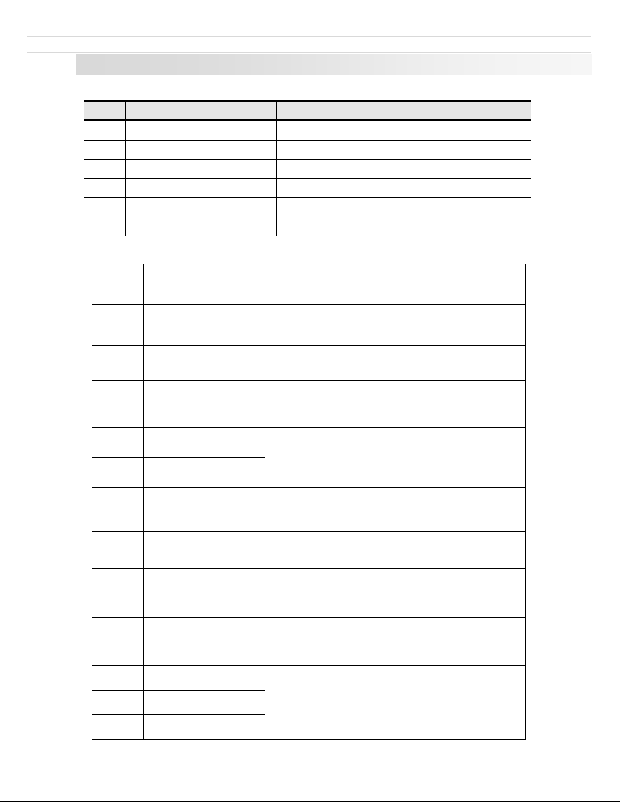
Legends:
“★”: this parameter’s setting value is not editable when inverter is at operation status;
“●”: this parameter’s value is observed value, not editable;
“☆”: this parameter’s setting value is editable when inverter is at stop or operation status;
“▲”: this parameter is “factory parameter” not for editing;
“-”: this parameter is depending on model.
Def: factory default settings
Res: restrictions when editing
4.1 Monitoring parameters: d0.00-d0.65
d0 group is used for monitoring inverter status. User can read by panel display or by remote communications.
d0.00~d0.31 are defined by P7.03 & P7.04.
Function code
Name
Unit
d0.00
Running frequency (Hz)
0.01Hz
Absolute value of theoretical running frequency.
d0.01
Set frequency (Hz)
0.01Hz
Absolute value of theoretical set frequency.
d0.02
DC Bus voltage (V)
0.1V
Detected value of DC bus voltage
d0.03
Output voltage (V)
1V
Actual value of inverter output voltage.
d0.04
Output current (A)
0.01A
Effective value of inverter output current.
d0.05
Output power (kW)
0.1kW
Value of inverter output power.
d0.06
Output torque (%)
0.1%
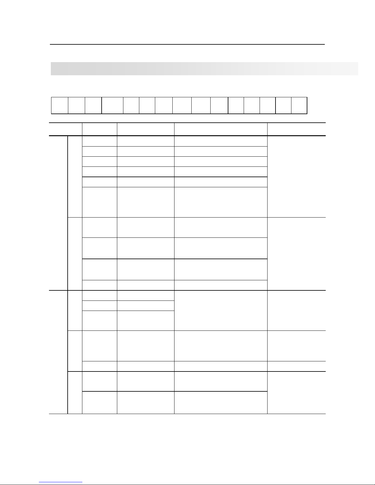
Value of inverter output torque percentage.
d0.07
DI input status
1
This displays the current state of DI terminals and the value is hexadecimal. Each bit corresponds
to a DI. "1" indicates high level signal, and "0" indicates low level signal. The corresponding
relationship between bits and DIs is described in the following table.
0~14 place
Input terminal status
0
invalid
1
valid
-20-
d0.08
DO output status
1
This displays the current state of DO terminals and the value is hexadecimal. Each bit corresponds
to a DO. "1" indicates high level signal, and "0" indicates low level signal. The corresponding
relationship between bits and DOs is described in the following table.
0~9 place
output terminal status
0
invalid
1
valid
d0.09
AI1 voltage after correction
V/mA
d0.10
AI2 current after correction
V/mA
d0.11
Keyboard command voltage
V/mA
d0.14
Load speed display
1
Motor actual running speed. Please refer to P7.12 for settings.
d0.15
PID setting value
1
PID preset value percentage.
d0.16
PID feedback
1
PID feedback value percentage.
d0.18
HDI (DI5) pulse frequency
0.01kHz
HDI (DI5) input pulse frequency display.
d0.19
Feedback speed
0.1Hz
11
14
13
12
2
11
2 2 2
121314
DI7
DI8
DI10
DI9
7 6
5
4
3
2
1
0
DI1
DI2
10
9
8
DI3
DI4
DI5
DI6
VDI5
VDI4
VDI3
VDI2
VDI1
2 2 2 2 2 2
2
2
0
1
234567
2 2 2
8910
7 6
5
4
3
2
1
0
FMR
TA1-TB1-TC1
9
8
TA2-TB2-TC2
DO1
DO2
VDO1
2 2 2 2 2 2
2
2
0
1
234567
2 2
89
VDO2
VDO3
VDO5
VDO4

-21-
PG feedback speed, accurate to 0.1Hz.
P7.12 determines location of decimal point for value of d0.19 & d0.29.
If P7.12=2, value range is -320.00Hz~320.00Hz;
If P7.12-1, value range is -500.0Hz~500.0Hz.
d0.20
Remaining running time
0.1Min
Used for timer control. Refer to P8.42~P8.44.
d0.21
AI1 voltage/current before correction.
0.001V
If P4.40=0, this displays voltage; if P4.40=1, this displays current.
d0.22
AI2 voltage before correction.
0.001V
If P4.40=0, this displays voltage; if P4.40=1, this displays current.
d0.23
Keyboard voltage before correction.
0.001V
If P4.40=0, this displays voltage; if P4.40=1, this displays current.
d0.28
Communication setting value
0.01%
It displays the data written from the communication address 0x1000.
d0.30
Main frequency X display
0.01Hz
P0.03 main frequency setting value
d0.31
Auxiliary
frequency Y display
0.01Hz
P0.04 auxiliary frequency setting value.
d0.35
Target torque
0.1%
Target torque is current torque upper limit.
d0.37
Power factor angle
-
d0.39
V/F separation target voltage
1V
Target voltage upon V/F separation
d0.40
V/F separation output voltage
1V
Output voltage upon V/F separation
d0.41
DI terminal status display
ON: high electrical level;
OFF: low electrical level.
d0.42
DO terminal status display
ON: high electrical level;
OFF: low electrical level.
d0.43
DI function display 1

-22-
This uses 5 nixie tubes to display whether terminal functions 1~40 are
valid. Each nixie tube can display 8 functions. From right to left: 1~8,
9~16, 17~24, 25~32, 33~40.
d0.44
DI function display 2
Same as d0.43, this uses 3 nixie tubes to display whether terminal functions 41~59 are valid. From
right to left: 41~48, 49~56, 57~59.
d0.59
Setting frequency percentage
%
d0.60
Running frequency percentage
%
d0.61
Inverter running status
d0.61
Bit0
0: Stop; 1: FWD; 2: REV
Bit1
Bit2
0: Constant speed; 1: Accelerate; 2: Decelerate
Bit3
Bit4
0: DC bus normal; 1: under-voltage
d0.62
Current fault code
d0.63
Point-to-point communication value sent
d0.64
Number of slaves
d0.65
Torque upper limit
4.2 Basic functions group: P0.00-P0.28
Code
Description
Setting range
Def
Res
P0.00
Load type
G type
1
-
●
P type
2
This parameter is to display the delivered model and cannot be modified.
1: Applicable to constant torque load with rated parameters specified
2: Applicable to variable torque load (fan and pump) with rated parameters specified.
P0.01
Speed control mode
Sensorless flux vector control (SVC)
0
2
★
V/F control
2
0: Sensorless flux vector control for asynchronous motors (SVC)
This is for high-performance control applications such as machine tool, centrifuge, wire drawing
machine and injection molding machine. One inverter can only drive one motor.
2: Voltage/Frequency control (V/F)
It is applicable to applications with low load requirements or applications where one inverter
operates multiple motors, such as fans and pumps.
Notes:
If vector control is used, motor auto-tuning must be performed because the advantages of vector
control can only be utilized after correct motor parameters are obtained. Better performance can be
achieved by adjusting speed regulator parameters in group P3.
For the permanent magnetic synchronous motor (PMSM), the DLA1 does not support SVC. FVC is
used generally. In some low-power motor applications, you can also use V/F.

-23-
P0.02
Command source
channel selection
Keyboard (LED OFF)
0
0
☆
Terminals (LED ON)
1
Communication (LED blinks)
2
This is to determine the input channel of the control commands, such as run, stop, forward rotation,
reverse rotation and jog operation.
0: Keyboard ("LOCAL" indicator off)
Commands are given by pressing keys on the keyboard (keyboard).
1: Terminals ("LOCAL" indicator on)
Commands are given by means of multi-functional input terminals with functions such as FWD,
REV, FJOG, and RJOG.
2: Communication ("LOCAL" indicator blinking)
Commands are given from communication with upper controllers. If this parameter is set to 2, a
communication card (Modbus RTU, PROFIBUS-DP card, CANlink card or CANopen card) must
be installed. Please refer to PD group function codes for communication settings.
P0.03
Main frequency source
X selection
Keyboard setting (P0.08, UP/DOWN
editable, not retentive at power off)
0
0
★
Keyboard setting (P0.08, UP/DOWN
editable, retentive at power off)
1
AI1 setting
2
AI2 setting
3
AI3 setting
4
Reserved
5
Multi-speed operation setting
6
Simple PLC setting
7
PID control setting
8
Remote communication setting
9
This is used to select the setting channel of the main frequency X.
0: Keyboard setting (P0.08, UP/DOWN editable, not retentive at power off)
The initial value of the set frequency is the value of P0.08 (Preset frequency). You can change the
frequency by pressing the keyboard (or using the UP/DOWN function of input terminals). When the
inverter is powered on again after power off, the frequency reverts to the value of P0.08.
1: Keyboard setting (P0.08, UP/DOWN editable, retentive at power off)
The initial value of the set frequency is the value of P0.08 (Preset frequency). You can change the
set frequency by pressing the keyboard (or using the UP/DOWN function of input terminals). When
the inverter is powered on again after power off, the frequency is the value memorized at the
moment of the last power off.
Note that P0.23 determines whether the set frequency is memorized or cleared when the inverter
stops. It is related to stop rather than power off.
2: AI1
3: AI2
4:
AI3 (keyboard potentiometer)
Jumper J6 determines whether to use AI3 terminal or keyboard potentiometer as command source.
If AI3 terminal is selected, Jumper J5 determines whether to use
0-10V voltage input or 0-20 mA
current input
-24-
6:
Multi-speed operation setting
In
multi-speed operation setting
mode, combinations of different DI terminal states correspond to
different set frequencies. The DLA1 supports maximum 16 speeds implemented by 16 state
combinations of four DI terminals in Group PC. The
multi-speed operation setting
indicates
percentages of the value of P0.10 (Maximum output frequency).
If a DI terminal is used for the
multi-speed operation setting
, you need to set in group P4.
7: Simple PLC setting
When the simple programmable logic controller (PLC) mode is used as the frequency source, the
running frequency of the inverter can be switched over among the 16 frequency references. You can
set the holding time and acceleration/deceleration time of the 16 frequency references. For details,
refer to the descriptions of Group PC.
8:
PID control setting
The output of PID control is used as the running frequency. PID control is generally used in on-site
closed-loop control, such as constant pressure closed-loop control and constant tension closed-loop
control. When applying PID as the frequency source, you need to set in group PA.
9:
Remote communication setting (RS485)
P0.04
Auxiliary frequency
source Y selection
Keyboard setting (P0.08, UP/DOWN
editable, not retentive at power off)
0
0
★
Keyboard setting (P0.08, UP/DOWN
editable, retentive at power off)
1
AI1 setting
2
AI2 setting
3
AI3 setting
4
Reserved
5
Multi-speed operation setting
6
Simple PLC setting
7
PID control setting
8
Remote communication setting
9
Refer to P0.03.
P0.05
Y reference in X and Y
combination
Relative to P0.10
0
0
☆
Relative to main frequency source X
1
P0.06
Y range in X and Y
combination
0%~150%
100%
☆
If X and Y combination is used, P0.05 and P0.06 are used to set the adjustment range of Y. You can
set Y to be relative to either maximum frequency or main frequency X. If relative to main frequency
X, the setting range of Y varies according to the main frequency X.
P0.07
Frequency source
combination mode
One’s
place
Frequency source selection
00
☆
Main frequency source X
0
Result of “X and Y combination”
1
X and Y switchover
2
X and “X and Y combination” switchover
3
-25-
Y and “X and Y combination” switchover
4
Ten’s
place
X and Y combinations
X+Y
0 X-Y
1
MAX [X, Y]
2
MIN [X, Y]
3
The final output frequency can be simple X setting, or it can be a sophisticated result after Y is
included and/or combined.
P0.08
Preset frequency
setting
0.00Hz~ P0.10 (
valid when frequency
source is digital setting
)
50
.
00Hz
☆
When frequency source selection is “digital setting” or “terminal UP/DOWN”, this value is inverter
frequency digital setting initial value.
P0.09
Operation direction
selection
Same direction
0
0
☆
Reverse direction
1
You can change the rotation direction of the motor just by modifying this parameter without
changing the motor wiring. Modifying this parameter is equivalent to exchanging any two of the
motor's U, V, W wires.
The motor will resume running in the original direction after parameter initialization. Do not use
this function in applications where changing the rotating direction of the motor is prohibited after
system commissioning is complete.
P0.10
Maximum frequency
50.00Hz~320.00Hz
50.00Hz
★
When the frequency source is AI, pulse setting (DI5), or multi-speed, value of this parameter
determines the 100% frequency.
The output frequency of the DLA1 can reach 3200 Hz. To take both frequency reference resolution
and frequency input range into consideration, you can set the number of decimal places for
frequency reference in P0.22.
• If P0.22 is set to 1, the frequency reference resolution is 0.1 Hz. In this case, the setting range of
P0.10 is 50.0 to 3200.0 Hz.
• If P0.22 is set to 2, the frequency reference resolution is 0.01 Hz. In this case, the setting range of
P0.10 is 50.00 to 320.00 Hz.
P0.11
Frequency source
upper limit
P0.12 setting
0
0
★
AI1 1 AI2
2
AI3
3
Reserved
4
Communication setting
5

-26-
It is used to set the source of the frequency upper limit, including digital setting (P0.12), AI, or
communication setting. If the frequency upper limit is set by means of AI1, AI2, AI3, or
communication, the setting is similar to that of the main frequency source X. For details, see the
description of P0.03.
For example, to avoid runaway in torque control mode in winding application, you can set the
frequency upper limit by means of analog input. When the inverter reaches the upper limit, it will
maintain at this speed.
P0.12
Frequency upper limit
Frequency lower limit P0.14 to maximum
frequency
P0.10
50.00Hz
☆
P0.13
Frequency upper limit
offset
0.00Hz~ maximum frequency P0.10
0.00Hz
☆
When frequency is set by analog or pulse, P0.13 is used as setting value offset value, and then
overlap with P0.11 to become final frequency upper limit.
P0.14
Frequency lower limit
0.00Hz~ upper limit frequency P0.12
0.00Hz
☆
If the frequency reference is lower than the value of this parameter, the inverter can stop, run at
the frequency lower limit, or run at zero speed, determined by P8.14.
P0.15
Carrier frequency
0.5kHz~12.0kHz
-
☆
Please refer to table below:
Carrier frequency
Low → High
Motor noise
Big → Small
Output current waveform
Bad → Good
Motor temperature rise
High → Low
Inverter temperature rise
Low → High
Leakage current
Small → Large
External radiation interference
Small → Large
The factory setting of carrier frequency varies with the inverter power. If you need to modify the
carrier frequency, note that if the set carrier frequency is higher than factory setting, it will lead
to an increase in temperature of the inverter's heatsink. In this case, you need to de-rate the
inverter. Otherwise, the inverter may overheat and alarm.
P0.16
Carrier frequency
adjustment based on
temperature
No 0
0
☆
Yes
1
It is used to set whether the carrier frequency is adjusted based on the temperature. The Inverter
automatically reduces the carrier frequency when detecting that the hea tsink temperature is high.
The inverter sets the carrier frequency to the set value when the heatsink temperature becomes
normal. This function reduces the overheat alarms.
P0.17
Acceleration time 1
0.00s~65000s
- ☆ P0.18
Deceleration time 1
0.00s~65000s
-
☆
Acceleration time is the time required by the inverter to accelerate from 0 Hz to
"Acceleration/Deceleration base frequency” (P0.25), that is, t1 in figure below.

-27-
Deceleration time is the time required by the Inverter to decelerate from
"Acceleration/Deceleration base frequency” (P0.25) to 0 Hz, that is, t2 in figure below.
The DLA1 provides totally four groups of acceleration/deceleration times. You can perform
switchover by using a DI terminal.
• Group 1: P0.17, P0.18
• Group 2: P8.03, P8.04
• Group 3: P8.05, P8.06
• Group 4: P8.07, P8.08
P0.19
Acceleration/decelerati
on time unit
1s
0
1
★
0.1s
1
0.01s
2
DLA1 provides three acceleration/ deceleration time units, 1s, 0.1s and 0.01s. Modifying this
parameter will make the displayed decimal places change and corresponding
acceleration/deceleration time also change.
P0.21
Y offset
0.00Hz~ maximum frequency P0.10
0
.
00Hz
☆
This parameter is valid only when the frequency source is set to "X and Y combination".
The final frequency is obtained by adding the frequency offset set in this parameter to the X and Y
combination result.
P0.22
Frequency reference
resolution
0.01Hz
2 2 ★
P0.23
Retentiveness of digital
setting at stop
Not retentive
0
0
☆
Retentive
1
This parameter is valid only when the frequency source is digital setting.
If P0.23 is set to 0, the digital setting value resumes to the value of P0.08 (Preset frequency) after the
inverter stops.
If P0.23 is set to 1, the digital setting value is the set frequency at the moment when the inverter
stops.
P0.25
Acceleration/Decelerati
on time base frequency
Maximum frequency (P0.10)
0
0
★
Set frequency
1
100Hz
2
The acceleration/deceleration time indicates the time for the inverter between 0 Hz and the
frequency set in P0.25.
P0.26
UP/DOWN base
frequency at running
Running frequency
0
0
★
Set frequency
1
-28-
This parameter is valid only when the frequency source is digital setting.
It is used to set the base frequency to be modified by using keys and or the terminal UP/DOWN
function.
P0.27
Binding frequency
source to command
source channels
One’s place
Binding frequency source to
keyboard
000
☆
No binding
0 Digital setting
1
AI1 2 AI2
3
AI3 4 Reserved
5
Multi-speed
6
Simple PLC
7
PID 8 Communication
9
Ten’s place
Binding frequency source to
terminals
No binding
0 Digital setting
1
AI1 2 AI2
3
AI3 4 Reserved
5
Multi-speed
6
Simple PLC
7
PID 8 Communication
9
Hundred’s
place
Binding frequency source to
communication
No binding
0
Digital setting
1
AI1
2
AI2 3 AI3
4
Reserved
5
Multi-speed
6
Simple PLC
7
PID 8 Communication
9

-29-
4.3 First motor parameters: P1.00-P1.37
Code
Description
Setting range
Def
Res
P1.00
Motor type selection
Normal asynchronous motor
0
0
★
Variable frequency asynchronous motor
1
P1.01
Motor rated power
0.1kW~1000.0kW
-
★ P1.02
Motor rated voltage
1V~2000V
-
★
P1.03
Motor rated current
0.01A~655.35A (inverter rated power≦55kW)
0.1A~6553.5A (inverter rated power >55kW)
-
★
P1.04
Motor rated
frequency
0.01Hz~ maximum frequency
-
★
P1.05
Motor rated speed
1rpm~65535rpm
-
★
Set these parameters according to the motor nameplate regardless of V/F control or vector control
is adopted. To achieve better V/F or vector control performance, motor auto-tuning is required,
which depends on the correct setting of motor nameplate parameters.
P1.06
Asynchronous motor
stator resistance
0.001Ω~65.535Ω (inverter rated power
≦
55kW)
0.0001Ω~6.5535Ω (inverter rated power >55kW)
- ★ P1.07
Asynchronous motor
rotor resistance
0.001Ω~65.535Ω (inverter rated power
≦
55kW)
0.0001Ω~6.5535Ω (inverter rated power >55kW)
-
★
P1.08
Asynchronous motor
leakage inductive
reactance
0.01mH~655.35mH (inverter rated power
≦
55kW)
0.001mH~65.535mH (inverter rated
power >55kW)
-
★
P1.09
Asynchronous motor
mutual inductive
reactance
0.1mH~6553.5mH (inverter rated power
≦
55kW)
0.01mH~655.35mH (inverter rated power >55kW)
-
★
P1.10
Asynchronous motor
no load current
0.01A~P1.03 (inverter rated power
≦
55kW)
0.1A~P1.03 (inverter rated power >55kW)
-
★
The parameters in P1.06 to P1.10 are asynchronous motor parameters. These parameters are
unavailable on the motor nameplate and are obtained by motor auto-tuning. Motor static autotuning can only obtain P1.06 to P1.08. Motor complete auto-tuning can obtain all parameters from
P1.06 to P1.10.
Each time "Motor rated power” (P1.01) or “Motor rated voltage" (P1.02) is changed, the inverter
automatically restores values of P1.06 to P1.10 to the parameter setting for the common standard
Y series asynchronous motor.
If it is impossible to perform motor auto-tuning onsite, manually input the values of these
parameters according to data provided by the motor manufacturer.
P1.37
Auto-tuning selection
No auto-tuning
0
0
★
Asynchronous motor static auto-
tuning 1
1
Asynchronous motor complete auto-
tuning
2
Asynchronous motor static auto-
tuning 2
3
1: Asynchronous motor static auto-tuning 1
It is applicable to scenarios where complete auto-tuning cannot be performed because the
asynchronous motor cannot be disconnected from the load.
Before performing static auto-tuning, properly set the motor type and motor nameplate parameters
of P1.00 to P1.05 first. The inverter will obtain parameters of P1.06 to P1.08 by static auto -tuning.
Set this parameter to 1, and press RUN. Then, the inverter starts static auto-tuning 1.

-30-
2: Asynchronous motor complete auto-tuning
To perform this type of auto-tuning, ensure that the motor is disconnected from the load. During
the process of complete auto-tuning, the inverter performs static auto-tuning first and then
accelerates to 80% of the motor rated frequency within the acceleration time set in P0.17. The
inverter keeps running for a certain period and then decelerates to stop within deceleration time set
in P0.18.
Before performing complete auto-tuning, properly set the motor type, motor nameplate parameters
of P1.00 to P1.05, "Encoder type” (P1.28) and "Encoder pulses per revolution” (P1.27) first.
The inverter will obtain motor parameters of P1.06 to P1.10, "A/B phase sequence of ABZ
incremental encoder" (P1.30) and vector control current loop PI parameters of P2.13 to P2.16 by
complete auto-tuning.
Set this parameter to 2, and press RUN. Then, the inverter starts complete auto-tuning.
3: Asynchronous motor static auto-tuning 1
This is applicable for asynchronous motors without encoders. During auto-tuning, the motor might
vibrate slightly. Please pay attention to safety.
Set this parameter to 3, and press RUN. Then, the inverter starts static auto-tuning 2.

-31-
4.4 V/F control parameters: P2.00-P2.27
Group P2 is valid only for V/F control. The V/F control mode is applicable to low load applications (fan
or pump) or applications where one inverter drives multiple motors or there is a large difference
between the inverter power and the motor power.
Code
Description
Setting range
Def
Res
P2.00
V/F curve setting
Linear V/F
0
0
☆
Multi-point V/F
1
Square V/F
2
1.2-time V/F
3
1.4-time V/F
4
1.5-time V/F
5
1.6-time V/F
6
1.7-time V/F
7
1.8-time V/F
8
Reserved
9
VF complete separation mode
10
VF half separation mode
11
0: Linear V/F
It is applicable to common constant torque load.
1: Multi-point V/F
It is applicable to special load such as dehydrator and centrifuge. Any such V/F curve can be
obtained by setting parameters of P2.03 to P2.08.
2: Square V/F
It is applicable to centrifugal loads such as fan and pump.
3 to 8: V/F curve between linear V/F and square V/F
10: V/F complete separation
In this mode, the output frequency and output voltage of the Inverter are independent. The output
frequency is determined by the frequency source, and the output voltage is determined by "Voltage
source for V/F separation" (P2.13).
It is applicable to induction heating, inverse power supply and torque motor control.
11: V/F half separation
In this mode, V and F are proportional and the proportional relationship can be set in P2.13. The
relationship between V and F are also related to the motor rated voltage and motor rated frequency
in Group P1.
Assume that the voltage source input is X (0 to 100%), the relationship between V and F is:
V/F = 2 * X * (motor rated voltage) / (motor rated frequency)
P2.01
Torque boost
0.0%~30%
-
★
P2.02
Torque boost cut-off frequency
0.00Hz~ maximum frequency
(P0.10)
50
.
00Hz
★

-32-
To compensate the low frequency torque characteristics of V/F control, user can boost the output
voltage of the inverter at low frequency by modifying P2.01.
If the torque boost is set to too large, the motor may overheat, and the inverter may suffer
overcurrent.
If the load is large and the motor startup torque is insufficient, increase the value of P2.01. If the
load is small, decrease the value of P2.01. If it is set to 0.0, the inverter performs automatic torque
boost. In this case, the inverter automatically calculates the torque boost value based on motor
parameters including the stator resistance.
P2.02 specifies the frequency under which torque boost is valid. Torque boost becomes invalid
when this frequency is exceeded.
P2.03
Multi-point V/F frequency 1 (F1)
0.00Hz~P2.05
0.00Hz
★
P2.04
Multi-point V/F voltage 1 (V1)
0.0%~100.0%
0.0%
★
P2.05
Multi-point V/F frequency 2 (F2)
P2.03~P2.07
0.00Hz
★
P2.06
Multi-point V/F voltage 2 (V2)
0.0%~100.0%
0.0%
★
P2.07
Multi-point V/F frequency 3 (F3)
P2.05~ motor rated frequency (P1.04)
0.00Hz
★
P2.08
Multi-point V/F voltage 3 (V3)
0.0%~100.0%
0.0%
★
These six parameters are used to define the multi-point V/F curve.
The multi-point V/F curve is set based on the motor's load characteristic. The relationship
between voltages and frequencies is:
V1 < V2 < V3, F1 < F2 < F3
At low frequency, higher voltage may cause overheat or even motor burn-out as well as overcurrent
stall or overcurrent protection of the inverter.

-33-
V1~V3: 1st, 2nd and 3rd voltage percentages of multi-point V/F
F1~F3: 1st, 2nd and 3rd frequency percentages of multi-point V/F
Vb: motor rated voltage
Fb: motor rated running frequency
P2.09
V/F slip compensation gain
0%~200.0%
0.0
%
☆
This parameter is valid only for the asynchronous motor.
It can compensate the rotational speed slip of the asynchronous motor when the load of the motor
increases, stabilizing the motor speed in case of load change.
If this parameter is set to 100%, it indicates that the compensation when the motor bears rated load
is the motor rated slip. The motor rated slip is automatically obtained by the inverter through
calculation based on the motor rated frequency and motor rated rotational speed in group P1.
Generally, if the motor rotational speed is different from the target speed, slightly adjust P2.09.
P2.10
V/F over-excitation gain
0~200
64
☆
During deceleration of the inverter, over-excitation can restrain rise of the DC bus voltage,
preventing the overvoltage fault. The larger the over-excitation is, the better the restraining result is.
Increase the over-excitation gain if the inverter is liable to overvoltage error during deceleration.
However, too large over-excitation gain may lead to an increase in the output current. Set P2.09 to a
proper value in actual applications.
Set the over-excitation gain to 0 in the applications where the inertia is small and the DC bus
voltage will not rise during motor deceleration or where there is a braking resistor.
P2.11
V/F oscillation suppression gain
0~100
-
☆
Set this parameter to a value as small as possible in the prerequisite of efficient oscillation
suppression to avoid influence on V/F control.
Set this parameter to 0 if the motor has no oscillation. Increase the value properly only when the
motor has obvious oscillation. The larger the value is, the better the oscillation suppression result
will be.
When the oscillation suppression function is enabled, the motor rated current and no-load current
must be correct. Otherwise, the V/F oscillation suppression effect will not be satisfactory.

-34-
P2.13
Voltage source for V/F
separation
Digital setting (
P2.14)
0
0
☆
AI1 1 AI2 2 AI3
3
Reserved
4
Multi-speed
5
Simple PLC
6
PID
7
Communication
8
100.0% corresponding to motor rated voltage (P1.02)
P2.14
V/F separation voltage digital
setting
0V~ motor rated voltage
0
V
☆
V/F separation is generally applicable to scenarios such as induction heating, inverse power supply.
If V/F separation is enabled, the output voltage can be set in P2.14 or by means of analog, multispeed, simple PLC, PID or communication. If you set the output voltage by means of non-digital
setting, 100% of the setting corresponds to the motor rated voltage. If a negative percentage is set,
its absolute value is used as the effective value.
0: Digital setting (P2.14)
The output voltage is set directly in P2.14.
1: AI1; 2: AI2; 3: AI3
The output voltage is set by AI terminals.
4: Reserved
5: Multi-speed
If the voltage source is multi-speed, parameters in group P4 and PC must be set to determine the
corresponding relationship between setting signal and setting voltage. 100.0% of the multi-speed
setting in group PC corresponds to the motor rated voltage.
6: Simple PLC
If the voltage source is simple PLC mode, parameters in group PC must be set to determine the
setting output voltage.
7: PID
The output voltage is generated based on PID closed loop. For details, see the description of PID in
group PA.
8: Communication setting
The output voltage is set by the host computer by means of communication.
The voltage source for V/F separation is set in the same way as the frequency source. For details,
see P0.03. 100.0% of the setting in each source corresponds to the motor rated voltage. If the
corresponding value is negative, its absolute value is used.
P2.15
Voltage rise time of V/F
separation
0.0s~1000.0s
0
.
0s
☆
P2.16
Voltage decline time of V/F
separation
0.0s~1000.0s
0
.
0s
☆

-35-
4.5 Vector control parameters: P3.00-P3.22
P3 group is valid for vector control, and invalid for V/F control.
Code
Description
Setting range
Def
Res
P3.00
Speed loop proportional gain G1
1~100
30
☆
P3.01
Speed loop integral time T1
0.01s~10.00s
0
.
50s
☆
P3.02
Switchover frequency 1
0.00~P2.05
5.00Hz
☆
P3.03
Speed loop proportional gain G2
0~100
20
☆
P3.04
Speed loop integral time T2
0.01s~10.00s
1.00s
☆
P3.05
Switchover frequency 2
P2.02~P0.10
10.00Hz
☆
Speed loop PI parameters can vary with running frequencies of the inverter.
• If the running frequency is less than or equal to "Switchover frequency 1" (P3.02), the speed
loop PI parameters are P3.00 and P3.01.
• If the running frequency is equal to or greater than "Switchover frequency 2" (P3.05), the speed
loop PI parameters are P3.03 and P3.04.
• If the running frequency is between P3.02 and P3.05, the speed loop PI parameters are obtained
from the linear switchover between the two groups of PI parameters, as shown in figure below.
PI
Frequency
P2.00
P2.01
P2.03
P2.04
P2.02 P2.05
The speed dynamic response characteristics in vector control can be adjusted by setting the
proportional gain and integral time of the speed regulator.
To achieve a faster system response, increase the proportional gain and reduce the integral time.
Be aware that this may lead to system oscillation.
The recommended adjustment method is as follows:
If the factory setting cannot meet the requirements, fine tune the PI parameters. Increase the
proportional gain first to ensure that the system does not oscillate, and then reduce the integral
time to ensure that the system has quick response and small overshoot.
Improper PI parameter setting may cause serious speed overshoot, and overvoltage fault may even
occur when the overshoot drops.

-36-
P3.06
Vector control slip gain
50%~200%
150%
☆
This is used to adjust speed stability accuracy of the motor. When the motor with load runs at a
very low speed, increase the value of this parameter; when the motor with load runs at a very large
speed, decrease the value of this parameter.
P3.07
SVC torque filter time constant
0.000s~0.100s
0
.
000s
☆
P3.09
Torque upper limit source in speed
control
P3.10
0
0
☆
AI1 1 AI2 2 AI3
3
Pulse (DI5)
4
Communication
5
Min (AI1, AI2)
6
Max (AI1, AI2)
7
P3.10
Torque upper limit in speed control
0.0%~200.0%
150
.
0%
☆
In speed control, the maximum output torque of the inverter is restricted by P3.09. If the torque
upper limit is analog, pulse or communication setting, 100% of the setting corresponds to the
value of P3.10, and 100% of the value of P3.10 corresponds to the inverter rated torque.
P3.13
Excitation adjustment proportional
gain
0~60000
2000
☆
P3.14
Excitation adjustment integral gain
0~60000
1300
☆
P3.15
Torque adjustment proportional
gain
0~60000
2000
☆
P3.16
Torque adjustment integral gain
0~60000
1300
☆
These are current loop PI parameters for vector control. These parameters are automatically
obtained through auto-tuning and need not be modified. The current loop integral regulator here is
integral gain rather than integral time. Note that too large current loop PI gain may lead to
oscillation of the entire control loop. Therefore, when current oscillation or torque fluctuation is
great, manually decrease the proportional gain or integral gain here.
P3.17
Speed loop integration
Invalid
0
0
☆
Valid
1
P3.18
Synchronous field weakening mode
No weakening
0
1
☆
Direct calculation
1
Automatic
2
P3.19
Field weakening depth
50%~500%
100%
☆
P3.20
Field weakening max current
1%~300%
50%
☆
P3.21
Field weakening adjustment gain
10%~500%
100%
☆
P3.22
Field weakening multiplier
2~10
2
☆
-37-
4.6 Input terminals: P4.00-P4.39
DLA1 provides six DI terminals (DI5 can be used for high-speed pulse input) and three analog input
(AI) terminals.
Code
Description
Setting range
Def
Res
P4.00
DI1 function selection
0~59
1
★
P4.01
DI2 function selection
0~59
4
★
P4.02
DI3 function selection
0~59
9
★
P4.03
DI4 function selection
0~59
12
★
P4.04
Reserved
0~59
13
★
P4.05
DI6 function selection
0~59
0
★
The following table lists the functions available for the DI terminals.
Value
Function
Description
0
No function
Set 0 for reserved terminals to avoid malfunction.
1
Forward RUN (FWD)
The terminal is used to control forward or reverse RUN
of the inverter.
2
Reverse RUN (REV)
3
Three-line mode control
The terminal determines three-line mode control of the
inverter. For details, see the description of P4.11.
4
Forward JOG (FJOG)
The JOG frequency, acceleration time and deceleration
time are described respectively in P8.00, P8.01 and
P8.02.
5
Reverse JOG (RJOG)
6
Terminal UP
If the frequency channel terminals, these two are used as
increment and decrement commands for frequency
modification. When the frequency source is digital
setting, they are used to adjust the frequency.
7
Terminal DOWN
8
Coast to stop
The inverter blocks its output, the motor coasts to rest
and is not controlled by the inverter. It is the same as
coast to stop described in P5.10.
9
Fault reset (RESET)
Same as RESET key on the keyboard. Remote fault reset
is implemented by this function.
10
Pause
The inverter decelerates to stop, but the running
parameters are all memorized. After this function is
disabled, the Inverter resumes its status before stop.
11
External fault normally
open (NO) input
If this signal is sent to the inverter, the inverter will
output 15=E.EIOF and performs the fault protection
action. For details please check P9.47.
12
Multi-speed terminal K1
The setting of 16 speeds or 16 other references can be
implemented through combinations of 16 states of these
four terminals.
Please refer to the next table.
13
Multi-speed terminal K2
14
Multi-speed terminal K3

-38-
15
Multi-speed terminal K4
16
Terminal 1 for
acceleration/
deceleration time
selection
Totally four groups of acceleration/deceleration time can
be selected through combinations states of these two
terminals.
17
Terminal 2 for
acceleration/
deceleration time
selection
18
Frequency source
switchover
This terminal is used to perform switchover between two
frequency sources according to the setting in P0.07.
19
UP/DOWN setting
clearance (terminal,
keyboard)
If the frequency source is digital setting, the terminal is
used to clear the modifications by using the UP/
DOWN function or the UP/DOWN key on keyboard,
returning the set frequency to the value of P0.08.
20
Command source
switchover terminal
If the command source is set to terminal control (P0.02
= 1), this terminal is used to perform switchover
between terminal control and keyboard control.
If the command source is set to communication control
(P0.02 = 2), this terminal is used to perform switchover
between communication control and keyboard control.
21
Acceleration/Decelerati
on prohibited
It enables the inverter to maintain the current frequency
output without being affected by external signals (except
the STOP command).
22
PID pause
PID is invalid temporarily. The inverter maintains the
current frequency output without PID adjustment of
frequency source.
23
PLC status reset
The terminal is used to restore the original status of PLC
control for the Inverter when PLC control is started
again after a pause.
24
Swing pause
The inverter outputs the central frequency, and the
swing frequency function pauses.
25
Counter input
This terminal is used to count pulses.
26
Counter reset
This terminal is used to clear the counter status.
27
Length count input
This terminal is used to count the length.
28
Length reset
This terminal is used to clear the length.
29
Torque control
prohibited
The inverter is prohibited from torque control and enters
the speed control mode.
30
Pulse input enabled
(only for DI5)
DI5 is used for pulse input.
31
Reserved
Reserved.
32
Immediate DC braking
The inverter directly switches over to the DC braking
state.
33
External fault normally
closed (NC) input
If this signal is sent to the inverter, the inverter will
output 15=E.EIOF and performs the fault protection
action. For details please check P9.47.
34
Frequency modification
prohibited
The inverter does not respond to any frequency
modification.

-39-
35
PID action direction
negation
The PID action direction is opposite to the direction set
in PA.03.
36
External STOP terminal
1
This terminal can be used to stop the Inverter, equivalent
to the STOP key on the keyboard.
37
Command source
switchover terminal 2
It is used to perform switchover between terminal
control and communication control. If the command
source is terminal control, the system will switch to
communication control after this terminal becomes ON.
38
PID integral pause
After this terminal becomes ON, the integral adjustment
function pauses. However, the proportional and
differentiation adjustment functions are still valid.
39
Switchover between
main frequency source
X and preset frequency
After this terminal becomes ON, the frequency source X
is replaced by the preset frequency set in P0.08.
40
Switchover between
auxiliary frequency source
Y and preset frequency
After this terminal is enabled, the frequency source Y is
replaced by the preset frequency set in P0.08.
41
Reserved
Reserved
42
Reserved
43
PID parameter
switchover
If the PID parameters switchover condition is DI
terminal (PA.18 = 1) and this terminal is invalid, the
valid PID parameters are PA.05 to PA.07; when this
terminal becomes valid, the valid PID parameters are
PA.15 to PA.17.
44
User-defined fault 1
If these two terminals become ON, the inverter reports
27=E.USt1 and 28=E.USt2 respectively, and performs
fault protection actions based on the setting in P9.49.
45
User-defined fault 2
46
Speed control/Torque
control switchover
This terminal enables the inverter to switch between
speed control and torque control. When this terminal
becomes OFF, the inverter runs in the mode set in
B0.00. When this terminal becomes ON, the inverter
switches over to the other control mode.
47
Emergency stop
When this terminal becomes ON, the inverter stops
within the shortest time. During stop, the current
remains at the current upper limit. This function is used
to for stopping the inverter in emergency situations.
48
External STOP terminal
2
In any control mode (keyboard, terminal or
communication), it can be used to make the inverter
decelerate to stop. In this case, the deceleration time is
deceleration time 4.
49
Deceleration DC
braking
When this terminal becomes ON, the inverter
decelerates to frequency set in P6.11 and then switches
to DC braking state.
50
Current running time
clearance
When this terminal becomes ON, the inverter's current
running time is cleared. This function needs to be
supported by P8.42 and P8.53.
51~59
Reserved
Reserved

-40-
Multi-speed control
K
4
K
3
K
2
K
1
Speed setting
Parameter
OFF
OFF
OFF
OFF
Speed 0
PC.
00
OFF
OFF
OFF
ON
Speed 1
PC.
01
OFF
OFF
ON
OFF
Speed 2
PC.
02
OFF
OFF
ON
ON
Speed 3
PC.
03
OFF
ON
OFF
OFF
Speed 4
PC.
04
OFF
ON
OFF
ON
Speed 5
PC.
05
OFF
ON
ON
OFF
Speed 6
PC.
06
OFF
ON
ON
ON
Speed 7
PC.
07
ON
OFF
OFF
OFF
Speed 8
PC.
08
ON
OFF
OFF
ON
Speed 9
PC.
09
ON
OFF
ON
OFF
Speed 10
PC.
10
ON
OFF
ON
ON
Speed 11
PC.
11
ON
ON
OFF
OFF
Speed 12
PC.
12
ON
ON
OFF
ON
Speed 13
PC.
13
ON
ON
ON
OFF
Speed 14
PC.
14
ON
ON
ON
ON
Speed 15
PC.
15
The value 100% of PC-00 to PC-15 corresponds to the value of P0.10 (maximum frequency).
Multi-speed can be also used as the PID setting source or the voltage source for V/F separation.
Acceleration/deceleration time setting
Two terminals for acceleration/deceleration time selection have four state combinations, as listed in
the following table.
Terminal 2
Terminal 1
Acceleration/ deceleration time selection
Parameters
OFF
OFF
Acceleration/Deceleration time 1
P0.17, P0.18
OFF
ON
Acceleration/Deceleration time 2
P8.03, P8.04
ON
OFF
Acceleration/Deceleration time 3
P8.05, P8.06
ON
ON
Acceleration/Deceleration time 4
P8.07, P8.08
P4.10
DI filter time
0.000s~1.000s
0
.
010s
☆
It is used to set the software filter time of DI terminal status. If DI terminals are liable to
interference and may cause malfunction, increase the value of this parameter to enhance the anti-
interference capability. However, increase of DI filter time will reduce the response of DI terminals.
P4.11
Terminal command mode
Two-line mode 1
0
0 ☆
Two-line mode 2
1
Three-line mode 1
2
Three-line mode 2
3
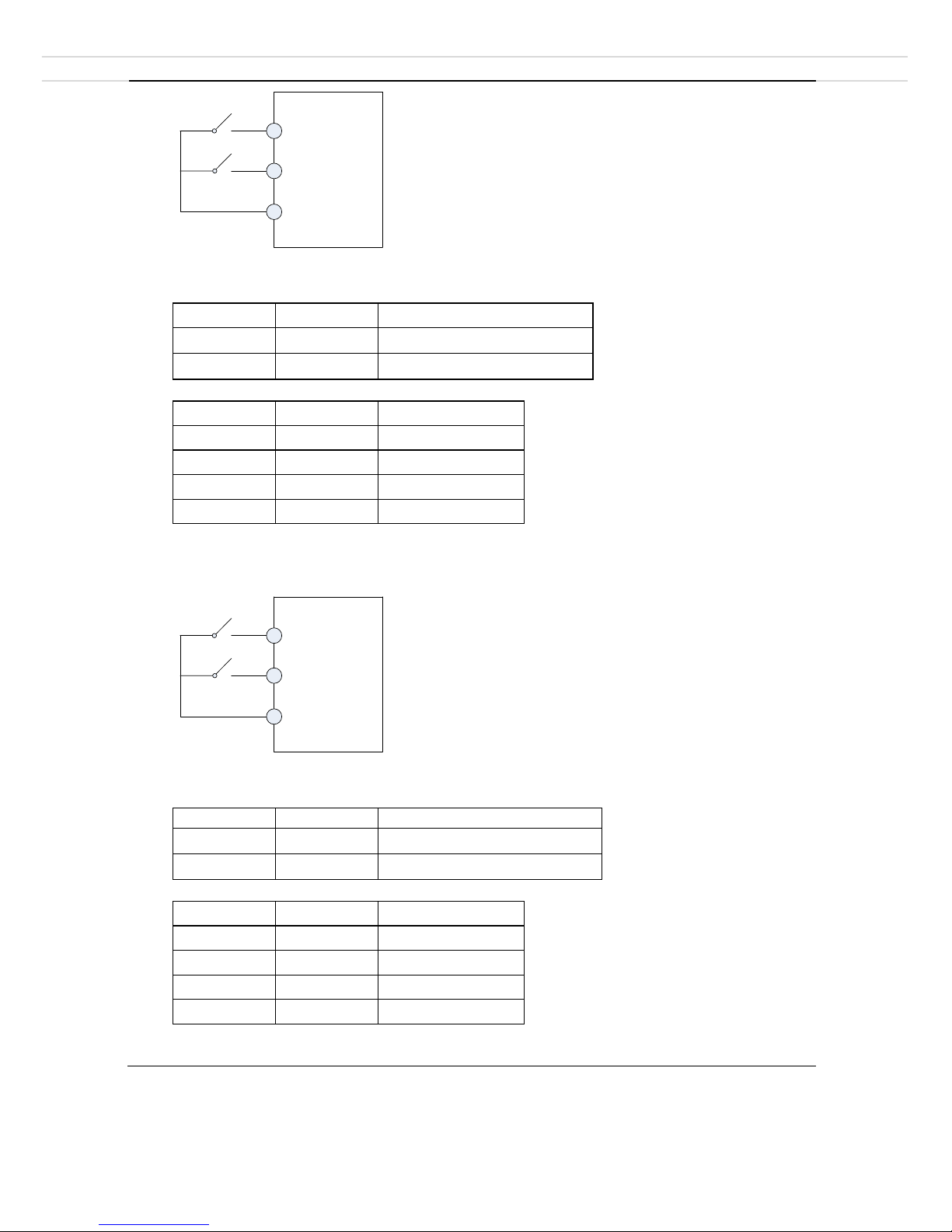
0: Two-line mode 1
-41-
DIx (FOR)
DIy (REV)
COM
K1
K2
It is the most commonly used two-line mode, in which the forward/reverse rotation of the motor is
decided by DI1x and DIy. The parameters are set as below:
Value
Function
Description
D
I
x
1
Forward operation (FWD)
D
I
y
2
Reverse operation (REV)
0: invalid; 1: valid.
K1
K2
Operation
0 0 Stop
0 1 REV
1 0 FWD
1 1 Stop
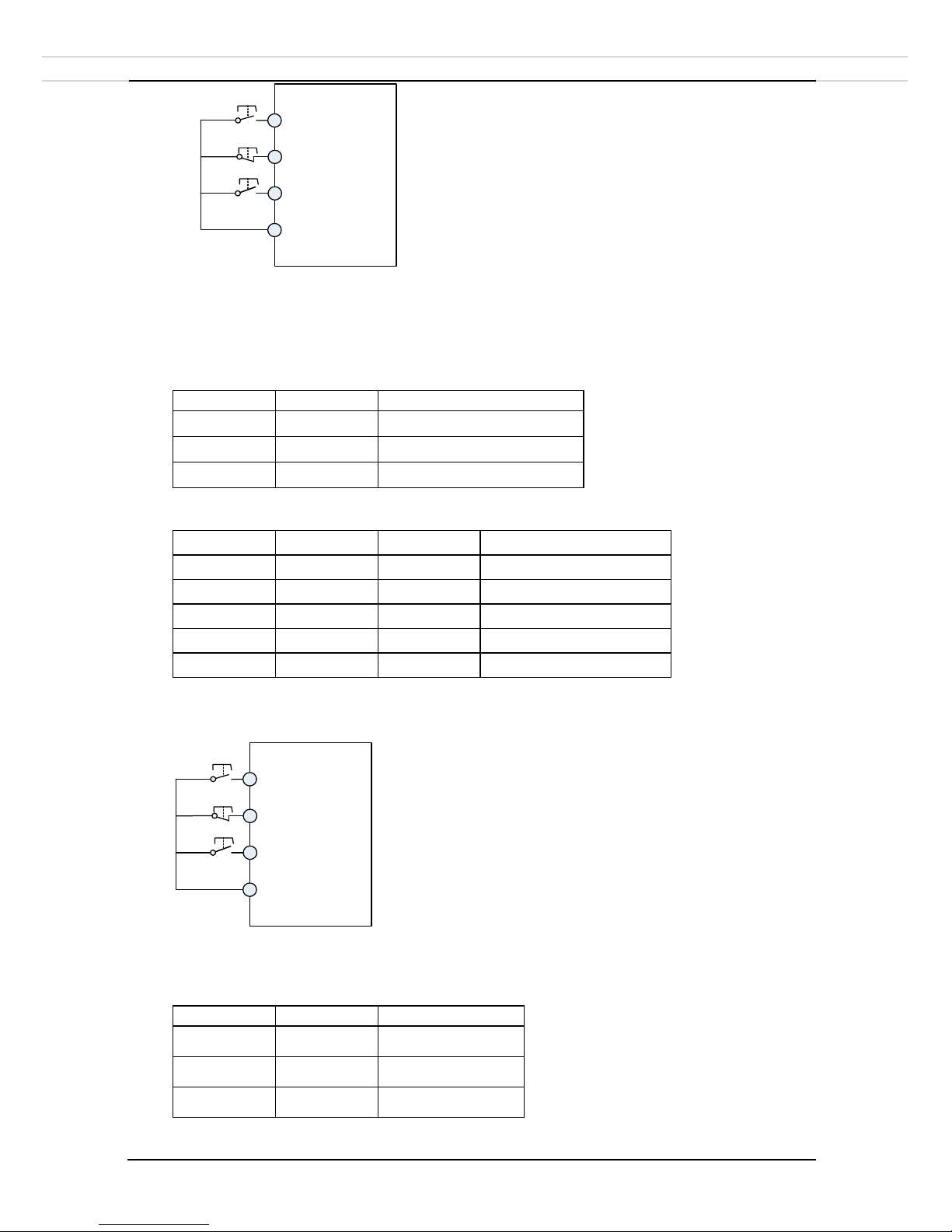
1: Two-line mode 2
DIx RUN enabled
DIy FWD or REV
COM
K1
K2
In this mode, DIx becomes ‘RUN enabled’ terminal, and DIy terminal decides operation
directions.
Value
Function
Description
D
I
x
1
RUN enabled
D
I
y
2
Directions (FWD or REV)
0: invalid; 1: valid.
K1
K2
Operation
0
0
Stop
0
1
Stop
1
0
FWD
1
1
REV
2: Three-line mode 1
-42-
COM
SB2
SB1
DIx (FWD)
DIy (REV)
DIn RUN enabled
SB3
SB1: Stop button
SB2: FWD button
SB3: REV button
In this mode, DIn is enable terminal, and DIx & DIy terminal decides operation directions.
Value
Function
Description
DIx
1
Forward operation (FWD)
DIy
2
Reverse operation (REV)
DIn
3
RUN enabled
0: invalid; 1: valid; X: random.
SB1
SB2
SB3
Operation
0 X X
Stop
1 1 0
FWD
1 0 1
REV
1 1 0->1
REV
1
0->1 1 FWD
3: Three-line mode 2;
COM
SB2
SB1
DIx RUN
DIy Direction
DIn Stop
K
SB1: Stop button
SB2: Run button
In this mode, DIx is enable terminal, DIn is stop terminal and DIy terminal decides operation
directions.
Value
Function
Description
DIx
1
RUN
DIy
2
Direction
DIn
3
Stop
0: invalid; 1: valid; X: random.

-43-
SB1
SB2 K Operation
0 X X
Stop
1 1 0
FWD
1 1 1
REV
P4.12
Terminal UP/DOWN rate
0.01Hz/s~655.35Hz/s
1.00Hz
/
s
☆
It is used to adjust the rate of change of frequency when the frequency is adjusted by means of
terminal UP/DOWN.
• If P0.22 (Frequency reference resolution) is 2, the setting range is 0.001-65.535 Hz/s.
• If P0.22 (Frequency reference resolution) is 1, the setting range is 0.01-655.35 Hz/s.
P4.13
AI curve 1 minimum input
0.00V~P4.15
0.00V
☆
P4.14
AI curve 1 minimum input percentage
-100.00%~100.0%
0.0%
☆
P4.15
AI curve 1 maximum input
P4.13~10.00V
10.00V
☆
P4.16
AI curve 1 maximum input percentage
-100.00%~100.0%
100.0%
☆
P4.17
AI1 filter time
0.00s~10.00s
0.10s
☆
These parameters are used to
define the relationship between
analog input voltage and the
corresponding setting. When
the analog input voltage
exceeds the maximum value
(P4.15), the maximum value is
used. When the analog input
voltage is less than the
minimum value (P4.13), the
value set in P4.34 (Setting for
AI less than minimum input) is
used.
When the analog input is
current input, 1 mA current
corresponds to 0.5 V voltage.
P4.17 (AI1 filter time) is used
to set the software filter time of
AI1. If the analog input is liable
to interference, increase the
value of this parameter to
stabilize the detected analog
input. However, increase of the
AI filter time will slow the response of analog detection. Set this parameter properly based on actual
conditions.
Graph on the right are two typical setting examples:
P4.18
AI curve 2 minimum input
0.00V~P4.20
0.00V
☆

-44-
P4.19
AI curve 2 minimum input percentage
-100.00%~100.0%
0.0%
☆
P4.20
AI curve 2 maximum input
P4.18~10.00V
10.00V
☆
P4.21
AI curve 2 maximum input percentage
-100.00%~100.0%
100.0%
☆
P4.22
AI2 filter time
0.00s~10.00s
0.10s
☆
P4.23
AI curve 3 minimum input
-10.00V~P4.25
0.10V
☆
P4.24
AI curve 3 minimum input percentage
-100.0%~100.0%
0.0%
☆
P4.25
AI curve 3 maximum input
P4.23~10.00V
4.00V
☆
P4.26
AI curve 3 maximum input percentage
-100.0%~100.0%
100.0%
☆
P4.27
AI3 filter time
0.00s~10.00s
0.10s
☆
These settings are same as AI curve 1 settings.
P4.33
AI
curve
selection
One’s place
AI1 curve selection
321
☆
Curve 1 (2 points, see P4-13 to P4-16)
1
Curve 2 (2 points, see P4-13 to P4-16)
2
Curve 3 (2 points, see P4-13 to P4-16)
3
Ten’s place
AI2 curve selection
Curve 1 (2 points, see P4-13 to P4-16)
1
Curve 2 (2 points, see P4-13 to P4-16)
2
Curve 3 (2 points, see P4-13 to P4-16)
3
Hundred’s place
AI3 curve selection
Curve 1 (2 points, see P4-13 to P4-16)
1
Curve 2 (2 points, see P4-13 to P4-16)
2
Curve 3 (2 points, see P4-13 to P4-16)
3
The one's place, ten's place and hundred's place of this parameter are respectively used to select the
corresponding curve of AI1, AI2 and AI3. Any of the 3 curves can be selected for AI1, AI2 and AI3.
P4.34
Setting for AI less
than minimum input
One’s place
AI1 setting
000
☆
Minimum value
0 0.0%
1
Ten’s place
AI2 setting
Minimum value
0
0.0%
1
Hundred’s place
AI3 setting
Minimum value
0 0.0%
1
This parameter is used to determine the corresponding setting when the analog input voltage is less
than the minimum value. The unit's digit, ten's digit and hundred's digit of this parameter
respectively correspond to the setting for AI1, AI2 and AI3.

-45-
If the value of a certain digit is 0, when analog input voltage is less than the minimum input, the
corresponding setting of the minimum input (P4.14, P4.19, P4.24) is used.
If the value of a certain digit is 1, when analog input voltage is less than the minimum input, the
corresponding value of this analog input is 0.0%.
P4.35
DI1 delay time
0.0s~3600.0s
0
.
0s
★
P4.36
DI2 delay time
0.0s~3600.0s
0
.
0s
★
P4.37
DI3 delay time
0.0s~3600.0s
0
.
0s
★
These parameters are used to set the delay time of the inverter when the status of DI terminals
changes. Currently, only DI1, DI2 and DI3 support the delay time function.
P4.38
DI level
selection
1
One’s place
DI1 level selection
00000
★
High level valid
0
Low level valid
1
Ten’s place
DI2 level selection
High level valid
0
Low level valid
1
Hundred’s place
DI3 level selection
High level valid
0
Low level valid
1
Thousand's place
DI4 level selection
High level valid
0
Low level valid
1
P4.39
DI level
selection
2
One’s place
DI6 level selection
00000
★
High level valid
0
Low level valid
1

-46-
4.7 Output terminals: P5.00-P5.22
DLA1 provides one analog output (AO) terminals, one digital output (DO) terminal, and one relay
terminal.
Code
Description
Setting range
Def
Res
P5.02
Relay 1 function (TA1-TB1-TC1)
0-41
2
☆
P5.04
DO1 function selection (open-collector output)
0-41
1
☆
The functions of the output terminals are described in the following table.
Value
Function
Description
0
No output
The terminal has no function.
1
Inverter running
When the inverter is running and has output
frequency (can be zero), the terminal becomes ON.
2
Fault output (stop)
When the Inverter stops due to a fault, the terminal
becomes ON.
3
Frequency-level detection
FDT1 output
Refer to the descriptions of P8.19 and P8.20.
4
Frequency reached
Refer to the descriptions of P8.21.
5
Zero-speed running (no
output at stop)
If the inverter runs with the output frequency of 0,
the terminal becomes ON. If the Inverter is in the
stop state, the terminal becomes OFF.
6
Motor overload pre-warning
The inverter judges whether the motor load exceeds
the overload pre-warning threshold before
performing the protection action. If the pre-warning
threshold is exceeded, the terminal becomes ON.
For motor overload parameters, see the descriptions
of P9.00 to P9.02.
7
Inverter overload prewarning
The terminal becomes ON 10s before the inverter
overload protection action is performed.
8
Set count value reached
The terminal becomes ON when the count value
reaches the value set in PB.08.
9
Designated count value
reached
The terminal becomes ON when the count value
reaches the value set in PB.09.
10
Length reached
The terminal becomes ON when the detected actual
length exceeds the value set in PB.05.
11
PLC cycle completed
When simple PLC completes one cycle, the
terminal outputs a pulse signal with width of 250
ms.
12
Accumulative running time
reached
If the accumulative running time of the Inverter
exceeds the time set in P8.17, the terminal becomes
ON.

-47-
13
Frequency limited
If the set frequency exceeds the frequency upper
limit or lower limit and the output frequency of the
inverter reaches the upper limit or lower limit, the
terminal becomes ON.
14
Torque limited
In speed control mode, if the output torque reaches
the torque limit, the inverter enters stall protection
state and meanwhile the terminal becomes ON.
15
Ready for RUN
If the inverter main circuit and control circuit power
becomes stable, and the inverter detects no fault and
is ready for RUN, the terminal becomes ON.
16
AI1 larger than AI2
When the input of AI1 is larger than the input of
AI2, the terminal becomes ON.
17
Frequency upper limit
reached
If the running frequency reaches the upper limit, the
terminal becomes ON.
18
Frequency lower limit
reached (no output at stop)
If the running frequency reaches the lower limit, the
terminal becomes ON. In the stop state, the terminal
becomes OFF.
19
Under voltage state output
If the inverter is in under voltage state, the terminal
becomes ON.
20
Communication
setting
Refer to the communication protocol.
21
Reserved
Reserved.
22
Reserved
Reserved.
23
Zero-speed running 2
(having output at stop)
If the output frequency of the inverter is 0, the
terminal becomes ON. In the state of stop, the
signal is still ON.
24
Accumulative power-on time
reached
If the inverter accumulative power-on time (P7.13)
exceeds the value set in P8.16, the terminal
becomes ON.
25
Frequency level detection
FDT2 output
Refer to the descriptions of P8.28 and P8.29.
26
Frequency 1 reached
Refer to the descriptions of P8.30 and P8.31.
27
Frequency 2 reached
Refer to the descriptions of P8.32 and P8.33.
28
Current 1 reached
Refer to the descriptions of P8.38 and P8.39.
29
Current 2 reached
Refer to the descriptions of P8.40 and P8.41.
30
Timing reached
If the timing function (P8.42) is valid, the terminal
becomes ON after the current running time of the
inverter reaches the set time.

-48-
31
AI1 input limit exceeded
If AI1 input is larger than the value of P8.46 (AI1
protection upper limit) or lower than the value of
P8.45 (AI1 protection lower limit), the terminal
becomes ON.
32
Load becoming 0
If the load becomes 0, the terminal becomes ON.
33
Reverse running
If the inverter is in the reverse running state, the
terminal becomes ON.
34
Zero current state
Refer to the descriptions of P8.34 and P8.35.
35
Module temperature reached
If the heatsink temperature of the inverter module
(P7.07) reaches the set module temperature
threshold (P8.47), the terminal becomes ON.
36
Software current limit
exceeded
Refer to the descriptions of P8.36 and P8.37.
37
Frequency lower limit
reached (having output at
stop)
If the running frequency reaches the lower limit, the
terminal becomes ON. In the stop state, the signal is
still ON.
38
Warning output
If a fault occurs on the inverter but the inverter
continues to run, this signal outputs.
39
Motor overheat pre-warning
If the motor temperature reaches the temperature set
in P9.58 (Motor overheat warning threshold), the
terminal becomes ON. You can view the motor
temperature by using d0.34.
40
Current running time
reached
If the current running time of inverter exceeds the
value of P8.53, the terminal becomes ON.
41
Fault output
Fault of coast to stop. No output at under voltage.
P5.07
AO1 output selection
0-16
0
☆ Value
Function
Description
0
Running frequency
0 to maximum output frequency
1
Set frequency
0 to maximum output frequency
2
Output current
0 to 2 times of motor rated current
3
Output torque
0 to 2 times of motor rated torque
4
Output power
0 to 2 times of rated power
5
Output voltage
0 to 1.2 times of inverter rated voltage
6
Pulse input
0.01-100.00kHz
7
AI1
0-10V (or 0-20 mA)
8
AI2
0-10V (or 0-20 mA)
9
AI3
0-10V (or 0-20 mA)
10
Length
0 to maximum set length

-49-
11
Count value
0 to maximum count value
12
Communication setting
0.0%-100.0%
13
Motor rotational speed
0 to rotational speed corresponding to
maximum output frequency
14
Output current
0.0-1000.0A
15
Output voltage
0.0-1000.0V
16
Output torque (actual value)
-2 times of motor rated torque ~ +2
times of motor rated torque
P5.10
AO1 zero offset coefficient
-100.0%~+100.0%
0.0% ☆ P5.11
AO1 gain
-10.00~+10.00
1.00
☆
P5.10~P5.11 are used to correct the zero drift of analog output and the output amplitude deviation.
They can also be used to define the desired AO curve.
If "b" represents zero offset, "k" represents gain, "Y" represents actual output, and "X" represents
standard output, the actual output is: Y = kX + b. The zero offset coefficient 100% of AO1
corresponds to 10V (or 20mA). The standard output refers to the value corresponding to the analog
output of 0 to 10V (or 0 to 20mA) with no zero offset or gain adjustment.
For example, if the analog output is used as the running frequency, and it is expected that the output is
8V (Y)when the frequency is 0 and 3V at the maximum frequency, the gain shall be set to -0.50 (k),
and the zero offset (b) shall be set to 80%.
P5.18
Relay 1 output delay time
0.0s~3600.0s
0
.
0s
☆
P5.20
DO1 output delay time
0.0s~3600.0s
0
.
0s
☆
P5.22
DO logic
selection
One’s place
FMR logic selection
00000
☆
Positive logic
0
Negative logic
1
Ten’s place
RELAY 1 logic selection
Positive logic
0
Negative logic
1
Hundred’s place
RELAY 2 logic selection
Positive logic
0
Negative logic
1
Thousand's place
DO1 logic selection
Positive logic
0
Negative logic
1
Ten thousand's place
DO2 logic selection
Positive logic
0
Negative logic
1
0: Positive logicThe output terminal is valid when being connected with COM, and invalid when
being disconnected from COM.
1: Negative logic
The output terminal is invalid when being connected with COM, and valid when being disconnected
from COM.

-50-
4.8 Start/stop control: P6.00-P6.15
Code
Description
Setting range
Def
Res
P6.00
Start mode
Direct start
0
0
☆
Speed tracking
1
Pre-excited start
2
0: Direct start
-If the startup DC braking time is set to 0, the inverter starts to run from the startup frequency.
-If the startup DC braking time is not 0, the inverter performs DC braking first and then starts to run
from the startup frequency. It is applicable to small-inertia load application where the motor is likely
to free rotate at startup.
1: Speed tracking
The inverter judges the rotational speed and direction of the motor first and then starts from the
tracked frequency. Such smooth start has no impact on the rotating motor. It is applicable to the
restart upon instantaneous power failure of large-inertia load. To ensure the performance of rotational
speed tracking restart, set the motor parameters in group P1 correctly.
2: Pre-excited start
It is valid only for asynchronous motor and used for building the magnetic field before the motor
runs. For pre-excited current and pre-excited time, see parameters of P6.05 and P6.06.
-If the pre-excited time is 0, the inverter cancels pre-excitation and starts from startup frequency.
-If the pre-excited time is not 0, the inverter pre-excites first before startup, improving the dynamic
response of the motor.
P6.01
Speed tracking mode
From frequency at stop
0
0
★
From industrial frequency
1
From maximum frequency
2
To complete the rotational speed tracking process within the shortest time, select the proper mode in
which the Inverter tracks the motor rotational speed.
0: From frequency at stop: It is the most common mode.
1: From zero frequency: It is applicable to restart after a long time of power failure.
2: From the maximum frequency: It is applicable to power-generating loads.
P6.02
Speed tracking rate
1~100
20
☆
The larger this value is, the faster the tracking is. However, too large may cause unreliable tracking.
P6.03
Startup frequency
0.00Hz~10.00Hz
0
.
00Hz
☆
P6.04
Startup frequency holding
time
0.0s~100.0s
0
.
0s
★
To ensure the motor torque at inverter startup, set a proper startup frequency. In addition, to build
excitation when the motor starts up, the startup frequency must be held for a certain period.
The startup frequency (P6.03) is not restricted by the frequency lower limit. If the target (digital
setting) frequency is lower than the startup frequency, the inverter will not start and stays in the
standby state.

-51-
During switchover between forward rotation and reverse rotation, the startup frequency holding time
is disabled. The holding time is not included in the acceleration time but in the running time of simple
PLC.
Example 1:
P0.03 = 0 The frequency source is digital setting.
P0.08 = 2.00Hz The digital setting frequency is 2.00 Hz.
P6.03 = 5.00Hz The startup frequency is 5.00 Hz.
P6.04 = 2.0s The startup frequency holding time is 2.0s.
In this example, the Inverter stays in the standby state and the output frequency is 0.00 Hz.
Example 2:
P0.03 = 0 The frequency source is digital setting.
P0.08 = 10.00Hz The digital setting frequency is 10.00 Hz.
P6.03 = 5.00Hz The startup frequency is 5.00 Hz.
P6.04 = 2.0s The startup frequency holding time is 2.0s.
In this example, the inverter accelerates to 5.00 Hz, and then accelerates to the set frequency 10.00Hz
after 2s.
P6.05
Startup DC braking
current/Pre-excited current
0%~100%
0%
★
P6.06
Startup DC braking
time/Pre-excited time
0.0s~100.0s
0
.
0s
★
Startup DC braking is generally used during restart of the inverter after motor stops. Pre-excitation is
used to make the inverter build magnetic field before startup to improve the responsiveness.
Startup DC braking is valid only for direct start (P6.00 = 0). In this case, the inverter performs DC
braking at the set startup DC braking current. After the startup DC braking time, the inverter starts to
run. If the startup DC braking time is 0, the inverter starts directly without DC braking. The larger the
startup DC braking current is, the larger the braking force is.
If the startup mode is pre-excited start (P6.00 = 3), the inverter builds magnetic field based on the
pre-excited current. After the pre-excited time, the inverter starts to run. If the pre-excited time is 0,
the inverter starts directly without pre-excitation.
The startup DC braking current or pre-excited current is a percentage relative to the base value.
• If the motor rated current is less than or equal to 80% of the inverter rated current, the base value is
the motor rated current.
• If the motor rated current is greater than 80% of the inverter rated current, the base value is 80% of
the inverter rated current.
P6.07
Acceleration/ Deceleration
mode
Linear acceleration/deceleration
0
0
★
S-curve acceleration/deceleration A
1
S-curve acceleration/deceleration B
2
0: Linear acceleration/deceleration.
The output frequency increases or decreases in linear mode. The DLA1 provides four group of
acceleration/deceleration time, which can be selected by using P4.00 to P4.08.

-52-
1: S-curve acceleration/deceleration A
The output frequency increases or
decreases along the S curve. This mode is
applicable where start and stop processes
needs to be smooth, such as elevator and
conveyor belt. P6.08 and P6.09
respectively define the time proportions of
the start segment and the end segment.
2: S-curve acceleration/deceleration B
In this curve, the motor rated frequency fb
is always the inflexion point. This mode
is applicable where faster
acceleration/deceleration is required
above rated frequency. When the set
frequency is higher than the rated
frequency, the acceleration/ deceleration
time is:
t = [(4/9) * (f/ fb) 2+5/9] * T
f is set frequency;
f
b
is motor rated frequency;
T is the acceleration time from 0 Hz to f
b
.
P6.08
Time proportion of S-curve
start segment
0.0%~ (100.0%-P6.09)
30
.
0%
★
P6.09
Time proportion of S-curve
end segment
0.0%~ (100.0%-P6.08)
30
.
0%
★
P6.08+P6.09≤100.0%
P6.10
Stop mode
Decelerate to stop
0
0
☆
Coast to stop
1
0: Decelerate to stop
After the stop command is enabled, the inverter decreases the output frequency according to the
deceleration time and stops when the frequency decreases to zero.
1: Coast to stop
After the stop command is enabled, the inverter immediately stops the output. The motor will coast to
stop based on the mechanical inertia.
P6.11
Stop DC braking initial
frequency
0.00Hz~ maximum frequency
0
.
00Hz
☆
P6.12
Stop DC braking waiting
time
0.0s~36.0s
0
.
0s
☆
P6.13
Stop DC braking current
0%~100%
0%
☆
P6.14
Stop DC braking time
0.0s~100.0s
0
.
0s
☆
P6.11 (
Stop DC braking initial frequency
)
During the process of decelerating to stop, the inverter starts DC braking when the running frequency
is lower than the value set in P6.11.
P6.12 (
Stop DC braking waiting time
)
t1
t2
t2
t1
time
t
output
frequency
Hz
set
frequency
f
Graph
4-11
S-curve acceleration/deceleration A
time
t
Output
Frequency Hz
f
Graph
4.12
S-curve acceleration/deceleration B
T
Rated
Frequenc
y
fb
Set
Frequency

-53-
When the running frequency decreases to the initial frequency of stop DC braking, the inverter stops
output for a certain period and then starts DC braking. This prevents faults such as overcurrent caused
due to DC braking at high speed.
P6.13 (Stop DC braking current)
This specifies the output current at DC braking and is a percentage relative to the base value.
o If the motor rated current is less than or equal to 80% of the inverter rated current, the base
value is the motor rated current.
o If the motor rated current is greater than 80% of the inverter rated current, the base value is
80% of the inverter rated current.
P6.14 (Stop DC braking time)
This specifies the holding time of DC braking. If it is set to 0, DC braking is cancelled.
P6.15
Brake use ratio
0%~100%
100%
☆
It is valid only for the inverter with internal braking unit and is used to adjust the duty ratio of the
braking unit. The larger this value, the better the braking result. However, too large value causes great
fluctuation of the inverter bus voltage during the braking process.

-54-
4.9 Keyboard and display: P7.00-P7.14
Code
Description
Setting range
Def
Res
P7.01
DIR/JOG
key
DIR/JOG
disabled
0
0
★
Switchover between keyboard control
and terminal/communication control
1
Switchover between forward rotation
and reverse rotation
2
Forward JOG
3
Reverse JOG
4
DIR/JOG key is a multifunctional key.
0: DIR/JOG key disabled
This key is disabled.
1: Switchover between keyboard control and terminal/communication control
You can perform switchover from the current command source to the keyboard control (local
operation). If the current command source is keyboard control, this key is invalid.
2: Switchover between forward rotation and reverse rotation
You can change the direction of the frequency reference by using the DIR/JOG key. It is valid only
when the current command source is keyboard control.
3: Forward JOG
You can perform forward JOG (FJOG) by using the DIR/JOG key.
4: Reverse JOG
You can perform reverse JOG (FJOG) by using the DIR/JOG key.
P7.02
STOP/RESET key
Valid only in keyboard control
0
1
☆
Valid in any operation mode
1
P7.03
Running state display 1
0000~FFFF
1
F
☆
If a parameter needs to be displayed at running, set the corresponding bit to 1, and set P7.03 to the
hexadecimal equivalent of the binary number.
7
6
5
4 3 2 1 0
Running
frequency
1(Hz)
Set
frequency
(Hz)
DC bus
Voltage
(V)
Output
voltage
(V)
Output
current
(A)
Output
power
(kW)
Output
Torque
(%)
DI
status
15
14
13
12
11
10 9 8
D0
status
Counter value
Length
Load speed
PID
setting
AI1
Voltage
(V)
AI2
Voltage
(V)
AI3
Voltage
(V)

-55-
P7.04
Running state display 2
0000~FFFF
0
☆
If a parameter needs to be displayed at running, set the corresponding bit to 1, and set P7.04 to the
hexadecimal equivalent of the binary number.
These two parameters are used to set the parameters that can be viewed when the inverter is in the
running state. You can view a maximum of 32 running state parameters that are displayed starting
from the lowest bit of P7.03.
P7.05
Stop state display
0000~FFFF
33
☆
If a parameter needs to be displayed at running, set the corresponding bit to 1, and set P7.04 to the
hexadecimal equivalent of the binary number.
P7.06
Load speed display
coefficient
0.0001~6.5000
1
.
0000
☆
This parameter is used to adjust the relationship between the output frequency of the inverter and the
load speed. For details, see the description of P7.12.
P7.07
Heatsink temperature of
inverting module
0.0℃~100.0℃
12
℃
●
It is used to display the insulated gate bipolar transistor (IGBT) temperature of the inverter, and the
IGBT overheat protection value of the inverter module depends on the model.
P7.08
Rectification module
temperature
0.0℃~100.0℃
0
℃
●
P7.09
Accumulative running time
0h~65535h
0h
●
It is used to display the accumulative running time of the inverter. After the accumulative running
time reaches the value set in P8.17, the terminal with the digital output function 12 becomes ON.
P7.10
Product number
Inverter product number
- ● P7.11
Software version
Software version of control board
-
●
15
14
13
12
11
10 9 8
Linear speed
Communication
Encoder speed
Power-on time
(Hour)
Running time
(Min)
Input pulse frequency
(Hz)
X Y 7 6 5 4 3 2 1 0 PID
feedback
Remaining running time
PLC
phase
Input pulse frequency
(kHz)
Running frequency
2 (Hz)
AI1
voltage
before correction
(V)
AI2
voltage
before correction
(V)
AI3
voltage
before correction
(V)
7 6 5 4 3 2 1
0
DI
status
set
frequency
(Hz)
bus
voltage
(V)
DO
status
AI1
voltage
AI2
voltage
AI3
voltage
counter
15
14
13
12
11
10 9 8
Length
reserved
reserved
reserved
PLC
phase
Load speed
PID
setting
Input pulse frequency
(Hz)
(V)
(V)
(V)
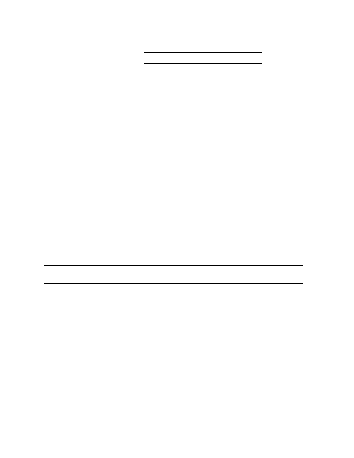
-56-
P7.12
Number of decimal places
for load speed display
One’s Place
21
☆
0 decimal place
0
1 decimal place
1
2 decimal place
2
3 decimal place
3
Ten’s Place
1 decimal place
1
2 decimal place
2
One’s Place:
P7.12 is used to set the number of decimal places for load speed display. The following gives an
example to explain how to calculate the load speed:
If P7.06 (Load speed display coefficient) is 2.000 and P7.12 one’s place is 2. When the running
frequency of the inverter is 40.00 Hz, the load speed is 40.00 x 2.000 = 80.00 (display of 2 decimal
places).
If the inverter is in the stop state, the load speed is the speed corresponding to the set frequency,
namely, "set load speed". If the set frequency is 50.00Hz, the load speed in the stop state is 50.00 x
2.000 = 100.00 (display of 2 decimal places).
Ten’s place:
1: d0.19/d0.29 are both displayed by one decimal point;
2: d0.19/d0.29 are both displayed by two decimal points.
P7.13
Accumulative power-on
time
0h~65535h
-
●
It is used to display the accumulative power-on time of the inverter since use. If the time reaches the
set power-on time (P8.17), the terminal with the digital output function 24 becomes ON.
P7.14
Accumulative power
consumption
0~65535 kWh
-
●
It is used to display the accumulative power consumption of the Inverter until now.

-57-
4.10 Auxiliary functions: P8.00-P8.54
Code
Description
Setting range
Def
Res
P8.00
JOG running frequency
0.00Hz~ maximum frequency
2
.
00Hz
☆
P8.01
JOG acceleration time
0.0s~6500.0s
20.0s
☆
P8.02
JOG deceleration time
0.0s~6500.0s
20.0s
☆
These parameters are used to define the set frequency and acceleration/deceleration time of the
inverter when Jogging. The startup mode is "Direct start" (P6.00 = 0) and the stop mode is
"Decelerate to stop" (P6.10 = 0) during jogging.
P8.03
Acceleration time 2
0.0s~6500.0s
10.0s
☆
P8.04
Deceleration time 2
0.0s~6500.0s
10.0s
☆
P8.05
Acceleration time 3
0.0s~6500.0s
10.0s
☆
P8.06
Deceleration time 3
0.0s~6500.0s
10.0s
☆
P8.07
Acceleration time 4
0.0s~6500.0s
10.0s
☆
P8.08
Deceleration time 4
0.0s~6500.0s
10.0s
☆
The DLA1 provides a total of four groups of acceleration/deceleration time. P0.17 and P0.18 are the
first group. Definitions of four groups are the same. You can switch over between the four groups
through different combinations of DI terminals. For more details, see P4.01 to P4.05.
P8.09
Jump frequency 1
0.00Hz~ maximum frequency
0.00Hz
☆
P8.10
Jump frequency 2
0.00Hz~ maximum frequency
0.00Hz
☆
P8.11
Frequency jump amplitude
0.00Hz~ maximum frequency
0.00Hz
☆
If the set frequency is within the frequency jump range, the actual running frequency is the jump
frequency nearby. Setting jump frequency helps to avoid the mechanical resonance point of the load.
DLA1 supports two jump frequencies. If both are set to 0, the frequency jump function is disabled.
The principle of the jump frequencies and jump amplitude is shown in the following figure.
P8.12
FWD/REV dead-zone time
0.00s~3000.0s
0
.
0s
☆
It is used to set the time when the output is 0 Hz at transition of the inverter forward rotation or
reverse rotation, as shown in the following figure.

-58-
P8.13
Reverse control
Enabled
0
0
☆
Disabled
1
It is used to set whether the inverter allows reverse rotation. In the applications where reverse
rotation is prohibited, set this parameter to 1.
P8.14
Running mode when set frequency
lower than frequency lower limit
Run at lower limit
0
0
☆
Stop (need start)
1
Run at zero speed
2
This is to set the inverter running mode when the set frequency is lower than frequency lower limit.
P8.15
Droop control rate
0.00Hz~10.00Hz
0
.
00Hz
☆
Droop control allows for slight speed differences between master and slaves so as to avoid conflicts.
The default value is 0.00Hz. Droop control is only needed when both master and slave are using
speed control. Please fine tune to find the most appropriate droop control value.
Please do not set P8.15 too large; otherwise when load is large, steady state speed will drop. Both
master and slave need to set droop control rates.
Droop speed = synchronous frequency * torque output * (P8.15/10)
For example, P8.15=1.00, synchronous frequency is 50Hz, torque output is 50%; then inverter
actual frequency is 50 – 50*(50%)*(1.00/10) =47.5Hz
P8.16
Accumulative power-on time
threshold
0h~65000h
0h
☆
If the accumulative power-on time (P7.13) reaches the value set in this parameter, the corresponding
DO terminal becomes ON.
For example, combining DI/DO functions, to implement the function that the inverter reports an
alarm when the actual accumulative power-on time reaches the threshold of 100 hours, perform the
setting as follows:
1) Set DI1 to user-defined fault 1: P4.00 = 44.
3) Set DO1 to power-on time reached: P5.04 = 24.
4) Set the accumulative power-on time threshold to 100h: P8.16 = 100h.
Then, the inverter outputs 26=E.ArA when the accumulative power-on time reaches 100 hours.
P8.17
Accumulative running time
threshold
0h~65000h
0h
☆
It is used to set the accumulative running time threshold of the Inverter. If the accumulative running
time (P7.09) reaches the value set in this parameter, the corresponding DO terminal becomes ON.
P8.18
Startup protection
No
0
0
☆
Yes
1
time
t
Output
Frequency
Hz
FWD
REV
dead-zone time

-59-
This parameter is used to set whether to enable the safety protection. If it is set to 1, the inverter
does not respond to the still valid run command upon inverter power-on (for example, an input
terminal is ON before power-on). The inverter responds only after the run command is cancelled
and becomes valid again.
In addition, the inverter does not respond to the still valid run command upon fault reset. The run
protection can be disabled only after the run command is cancelled.
In this way, the motor can be protected from responding to run commands upon power-on or fault
reset in unexpected conditions.
P8.19
Frequency detection value (FDT1)
0.00Hz~ maximum frequency
50.00Hz
☆
P8.20
Frequency detection hysteresis rate
(FDT hysteresis 1)
0.0%~100.0% (FDT1 level)
5.0%
☆
If the running frequency is higher than the value of P8.19, the corresponding DO terminal becomes
ON. If the running frequency is lower than value of P8.19, the DO terminal goes OFF
These two parameters are respectively used to set the detection value of output frequency and
hysteresis value upon cancellation of the output. The value of P8.20 is a percentage of the hysteresis
frequency to the frequency detection value (P8.19).
The FDT function is shown in the following figure.
P8.21
Frequency reached detection range
0~100% (maximum frequency)
0
.
0%
☆
If the Inverter running frequency is within this range of the set frequency, the corresponding DO
terminal becomes ON.
This parameter is used to set the range within which the output frequency is detected to reach the set
frequency. The value of this parameter is a percentage relative to the maximum frequency. The
detection range of frequency reached is shown in the following figure.

-60-
P8.22
Jump frequency validity in
acceleration/deceleration
Disabled
0
0
☆
Enabled
1
When P8.22=1, and the running
frequency is within the frequency
jump range, the actual running
frequency will jump over the set
frequency jump amplitude.
The figure shows when the jump
frequencies are valid in
acceleration/deceleration.
P8.25
Frequency switchover point
between acceleration time 1 and
acceleration time 2
0.00Hz~ maximum frequency
0.00Hz
☆
P8.26
Frequency switchover point
between deceleration time 1 and
deceleration time 2
0.00Hz~ maximum frequency
0.00Hz
☆
This function is valid when motor 1 is selected and acceleration/deceleration time switchover is not
performed by DI terminal. It is used to select different groups of acceleration/ deceleration time
based on the running frequency rather than DI terminal during the running process of the inverter.

-61-
During acceleration, if the running frequency is smaller than the value of P8.25, acceleration time 2
is selected. If the running frequency is larger than the value of P8.25, acceleration time 1 is selected.
During deceleration, if the running frequency is larger than the value of P8.26, deceleration time 1 is
selected. If the running frequency is smaller than the value of P8.26, deceleration time 2 is selected.
P8.27
Terminal JOG priority
Invalid
0
0
☆
Valid
1
If terminal JOG priority is valid, the inverter switches to terminal JOG running state when there is a
terminal JOG command during the running process of the inverter.
P8.28
Frequency detection value (FDT2)
0.00Hz~ maximum frequency
50
.
00Hz
☆
P8.29
Frequency detection hysteresis
(FDT hysteresis 2)
0.0%~100.0% (FDT2 Level)
5.0
%
☆
The frequency detection function is the same as FDT1 function. For details, refer to the descriptions
of P8.19 and P8.20.
P8.30
Frequency reached detection value 1
0.00Hz~ maximum frequency
50.00Hz
☆
P8.31
Frequency reached detection
amplitude 1
0.0%~100.0% (maximum
frequency)
0.0%
☆
P8.32
Frequency reached detection value 2
0.00Hz~ maximum frequency
50.00Hz
☆
P8.33
Frequency reached detection
amplitude 2
0.0%~100.0% (maximum
frequency)
0.0%
☆
Running frequency
time
t
Any frequency
reaching detection
value
Any Frequency
detection value
DO or relay
ON
ON
OFF OFF OFF
Any frequency reaching detection amplitude
Any frequency reaching detection amplitude

-62-
If the output frequency of the inverter is within the positive and negative amplitudes of frequency
reached detection value, the corresponding DO (P5.01=26/27) becomes ON.
DLA1 provides two groups of frequency reached detection parameters, including frequency
detection value and detection amplitude, as shown in the graph above.
P8.34
Zero current detection level
0.0%~300.0% (motor rated current)
5.0%
☆
P8.35
Zero current detection delay time
0.00s~600.00s
0.10s
☆
If the output current of the inverter is equal to or less than the zero current detection level and the
duration exceeds the zero current detection delay time, the corresponding DO (P5.01=34) becomes
ON. The zero current detection is shown in the following figure.
P8.36
Output over-current threshold
0.0% (No detection)
0.1%~300.0% (motor rated current)
200.0%
☆
P8.37
Output over-current detection delay
time
0.00s~600.00s
0.00s
☆
Zero current
detection
signal
t
t
ON
P8.34
P8.35
Output
current

-63-
If the output current of the inverter is equal to or higher than the overcurrent threshold and the
duration exceeds the detection delay time, the corresponding DO (P5.01=36) becomes ON. The
output overcurrent detection function is shown in the graph above.
P8.38
Current reached 1
0.0%~300.0% (motor rated current)
100.0%
☆
P8.39
Current reached amplitude 1
0.0%~300.0% (motor rated current)
0.0%
☆
P8.40
Current reached 2
0.0%~300.0% (motor rated current)
100.0%
☆
P8.41
Current reached amplitude 2
0.0%~300.0% (motor rated current)
0.0%
☆
If the output current of the inverter is within the positive and negative amplitudes of current reached
detection value, the corresponding DO (P5.01=28/29) becomes ON.
P8.42
Timing function
Disabled
0
0
☆
Enabled
1
P8.43
Timing duration source
P8.44 setting
0
0
☆
AI1
1
AI2
2
AI3
3
Output
current
Output
over-current
signal
t t P8.36
ON
P8.37
ON ON
ON
OFF OFF OFF
Any current reaching amplitude
Any current reaching amplitude
Any current detection
DO
or relay
Output
current
time
t
Any current
reaching

-64-
4.11 Fault and protection: P9.00-P9.73
Code
Description
Setting range
Def
Res
P9.00
Motor overload protection
selection
Disabled
0
1
☆
Enabled
1
P9.01
Motor overload protection (time)
gain
0.20~10.00
1
.
00
☆
P9.00 = 0
P8.44
Timing duration
0.0Min~6500.0Min
0
.
0Min
☆
If P8.42 is set to 1, the inverter starts timing at startup. When the set timing duration is reached, the
inverter stops automatically and meanwhile the corresponding DO (P5.01=30) becomes ON.
The inverter starts timing from 0 each time it starts up and the remaining timing duration can be
queried by d0.20.
The timing duration is set in P8.43 and P8.44, in unit of minute.
P8.45
AI1 protection lower limit
0.00V~P8.46
3.10V
☆
P8.46
AI1 protection upper limit
P8.45~10.00V
6.80V
☆
These two parameters are used to set the limits of the input voltage to provide protection on the
Inverter. When the AI1 input is larger than the value of P8.46 or smaller than the value of P8.45, the
corresponding DO (P5.01=31) becomes ON, indicating that AI1 input exceeds the limit.
P8.47
Module temperature threshold
0.00℃~100℃
75℃
☆
When the heatsink temperature of the Inverter reaches the value of this parameter, the corresponding
DO (P5.01=35) becomes ON, indicating that the module temperature reaches the threshold.
P8.49
Wakeup frequency
Dormant frequency (P8.51) ~
maximum frequency (P0.10)
0.00Hz
☆
P8.50
Wakeup delay time
0.0s~6500.0s
0.0s
☆
P8.51
Dormant frequency
0.00Hz~wakeup frequency (P8.49)
0.00Hz
☆
P8.52
Dormant delay time
0.0s~6500.0s
0.0s
☆
When the inverter is in running state, if the set frequency is lower than or equal to the dormant
frequency (P8.51), the inverter enters the dormant state and stops automatically after the dormant
delay time (P8.52).
When the inverter is in dormant state and the current running command is effective, if the set
frequency is higher than or equal to the wakeup frequency (P8.49), the inverters starts up after the
wakeup delay time (P8.50).
Generally, set the wakeup frequency equal to or higher than the dormant frequency. If the wakeup
frequency and dormant frequency are set to 0, the dormant and wakeup functions are disabled.
When the dormant function is enabled, if the frequency source is PID, whether PID operation is
performed in the dormant state is determined by PA.28. In this case, select PID operation enabled in
the stop state (PA.28 = 1).
P8.53
Current running time reached
0.0Min~6500.0Min
0
.
0Min
☆
Check P5.01=40.
P8.54
Output power adjustment
coefficient
0.0%~200.0%
100.0%
☆
When the output power (d0.05) is not equal to the required value, you can perform linear correction
on output power by using this parameter.

-65-
The motor overload protective function is disabled. The motor is exposed to potential overheating. A
thermal relay is suggested to be installed between the Inverter and the motor.
P9.00 = 1
The inverter judges whether the motor is overloaded according to the inverse time-lag curve of the
motor overload protection.
The inverse time-lag curve of the motor overload protection is:
Motor Current (percentage of motor rated current)
Overload time (minutes)
115%
80
125%
40
135%
15
145%
6
155%
4
165%
2.5
175%
2
185%
1.5
195%
1 (60s)
225%
0.5 (30s)
245%
0.17 (10s)
P9.01 can increase or decrease the overload time by linear proportions. If the value of P9.01 is set
too large, damage to the motor may result because the motor overheats but the Inverter does not
report the alarm.
Example 1: Motor rated current is 100A.
If P9.01=1 (default), when motor current reaches 125% of 100A (125A) and lasts for 40 minutes,
the inverter will output 11=E.oLt;
If P9.01=1.2, when motor current reaches 125% of 100A (125A) and lasts for 40*1.2=48 minutes,
the inverter will output 11=E.oLt.
Example 2: Inverters needs to output 11=E.oLt after motor running 2 minutes at 150% current.
150% (I) current is between 145% (I1) and 155% (I2); overload time should be between 6 minutes
(T1) and 4 minutes (T2).
If P9.01=1 (default), T=T1+(T2-T1) * (I-I1)/(I2-I1) =4+(6-4) *(150%-145%)/ (155%-145%)=5
minutes.
To make this time to be 2 minutes, set P9.01=2/5=0.4.

-66-
P9.02
Motor overload pre-warning
delay time coefficient
50%~100%
80%
☆
The inverter can give a pre-warning signal to the control system via DO or relay before motor
overload protection. The larger this value is; the longer delay of the pre-warning will be.
For example, P9.01=1, P9.02=80%, when motor current reaches 145% and lasts for 4.8 minutes
(80%*6), inverter will output motor overload pre-warning (P5.01=6).
P9.07
Power-on short-circuit to ground
protection
Disabled
0
1
☆
Enabled
1
It is used to determine whether to check the motor is short-circuited to ground at power-on. If this
function is enabled, the inverter's UVW will have voltage output a while after power-on.
P9.08
Brake unit action initial voltage
700~800V
780V
☆
Requirement: 800V≥P9.08≥(1.414*Vs+30)
Vs: input voltage of inverter
P9.09
Fault auto reset times
0~20
0
☆
It is used to set the times of fault auto resets if this function is used. After the value is exceeded, the
inverter will remain in the fault state.
P9.10
DO action during fault auto reset
No action
0
0
☆
Action
1
It is used to decide whether the DO acts during the fault auto reset if the fault auto reset function is
selected.
P9.11
Time interval of fault auto reset
0.1s~100.0s
1
.
0s
☆
It is used to set the waiting time from the alarm of the Inverter to fault auto reset.
P9.12
Input phase loss
protection
One’s place
Input phase loss protection
11
☆
Disabled
0
Enabled
1
Ten’s place
Contactor energizing protection
Disabled
0
Enabled
1
It is used to determine whether to perform input phase loss or contactor energizing protection.
(Only available for DLA1 series inverter over 18.5KW models)
P9.13
Output phase loss protection
selection
Disabled
0
1
☆
Enabled
1
It is used to determine whether to perform output phase loss protection.
P9.14
1st fault type
0~51
-
●
P9.15
2nd fault type
0~51
-
●
P9.16
3rd (latest) fault type
0~51
-
●

-67-
It is used to record the types of the most recent three faults of the inverter. 0 indicates no fault. For
possible causes and solution of each fault, refer to Chapter 6.
Fault types:
Number
Fault display
Fault type
0
No
No fault
1
1=E.IGbt
IGBT protection
2
2=E.oCAC
Acceleration over current
3
3=E.oCdE
Deceleration over current
4
4=E.oCCo
Constant speed over current
5
5=E.oUAC
Acceleration over voltage
6
6=E.oUdE
Deceleration over voltage
7
7=E.oUCo
Constant speed over voltage
8
8=E.CPF
Control power fault
9
9=E.LU
Under voltage fault
10
10=E.oL1
Inverter overload
11
11=E.oLt
Motor overload
12
12=E.ILF
Input phase loss
13
13=E.oLF
Output phase loss
14
14=E.oH1
Module overheat
15
15=E.EIoF
External fault
16
16=E.CoF1
Communication fault
17
17=E.rECF
Contactor fault
18
18=E.HALL
Current detection fault
19
19=E.tUnE
Motor auto-tuning fault
20
20=E.PG1
Encoder fault
21
21=E.EEP
EEPROM read & write fault
22
22=E.HArd
Inverter hardware fault
23
23=E.SHot
Grounding fault
24
No
Reserved
25
No
Reserved
26
26=E.ArA
Accumulative running time reached fault
27
27=E.USt1
User defined fault 1
28
28=E.USt2
User defined fault2
29
29=E.APA
Power-on time reached
30
30=E.ULF
Load becoming 0 fault
31
31=E.PID
PID feedback lost during running
40
40=E.CbC
IGBT current limiting fault
41
41=E.tSr
Running motor switchover fault
42
42=E.SdL
Speed deviation too large
43
43=E.oSF
Motor over speed
45
45=E.oHt
Motor over heat
51
51=E.PoSF
Initial position fault
P9.17
3rd fault frequency
●
It displays the frequency when the latest fault occurs.
P9.18
3rd fault current
● It displays the current when the latest fault occurs.
P9.19
3rd fault DC bus voltage
●
It displays the bus voltage when the latest fault occurs.
P9.20
3rd fault DI status
●

-68-
It displays the status of all DI terminals when the latest fault occurs. The sequence is as follows:
If a DI is ON, the setting is 1. If the DI is OFF, the setting is 0. The value is the equivalent
decimal number converted from the DI status.
P9.21
3rd fault output status
●
It displays the status of all output terminals when the latest fault occurs. The sequence is as follows:
If an output terminal is ON, the setting is 1. If the output terminal is OFF, the setting is 0. The
value is the equivalent decimal number converted from the DI statuses
P9.22
3rd fault inverter status
Reserved
●
P9.23
3rd fault power-on time
●
It displays the present power-on time when the latest fault occurs.
P9.24
3rd fault running time
●
It displays the present running time when the latest fault occurs.
P9.27
2nd fault frequency
●
It displays the frequency when the 2
nd
fault occurs.
P9.28
2nd fault current
●
It displays the current when the 2
nd
fault occurs.
P9.29
2nd fault DC bus voltage
●
It displays the bus voltage when the 2
nd
fault occurs.
P9.30
2nd fault DI status
● Refer to P9.20
P9.31
2nd fault output status
● Refer to P9.21
P9.32
2nd fault inverter status
Reserved
●
P9.33
Power-on time upon 2nd fault
●
It displays the present power-on time when the 2
nd
fault occurs.
P9.34
2nd fault running time
●
It displays the present running time when the 2
nd
fault occurs.
P9.37
1st fault frequency
●
It displays the frequency when the latest 1
st
occurs.
P9.38
1st fault current
●
It displays the current when the 1
st
fault occurs.
P9.39
1st fault DC bus voltage
●
It displays the bus voltage when the 1
st
fault occurs.
BIT9 BIT8 BIT7 BIT6 BIT5 BIT4 BIT3 BIT2 BIT1 BIT0
DI1 DI2 DI3 DI4 DI5 DI6 DI7 DI8 DI9 DI0
BIT4 BIT3 BIT2 BIT1 BIT0
FMP REL1 REL2
DO1
DO2

-69-
P9.40
1st fault DI status
●
Refer to P9.20
P9.41
1st fault output status
● Refer to P9.21
P9.42
1st fault inverter status
Reserved
●
P9.43
1st fault power-on time
●
It displays the present power-on time when the 1
st
fault occurs.
P9.44
1st fault running time
●
It displays the present running time when the 1
st
fault occurs.

-70-

-71-
If "Coast to stop" is selected, the inverter displays E.**** and directly stops.
If "Stop by stop mode" is selected, the inverter displays A.**** and stops according to the stop
mode. After stop, the inverter displays E.****.
If "Resume running" is selected, the inverter continues to run and displays A.****. The running
frequency is set in P9.54.
P9.54
Frequency selection for
resuming running upon fault
Current running frequency
0
0
☆
Set frequency
1
Frequency upper limit
2
Frequency lower limit
3
Backup frequency upon abnormality
4
P9.55
Backup frequency upon
abnormality
60.0%~100.0%
100
.
0%
☆
If a fault occurs during the running of the inverter and the handling of fault is set to "resume
running", the inverter displays A.** and continues to run at the frequency set in P9.54.
The setting of P9.55 is a percentage relative to the maximum frequency.
P9.56
Motor temperature sensor type
No temperature sensor
0
0
☆
PT100
1
PT1000
2
P9.57
Motor overheat protection
threshold
0℃~200℃
110℃
☆
P9.58
Motor overheat pre-warning
threshold
0℃~200℃
90℃
☆
The signal of the motor temperature sensor needs to be connected to the optional I/O extension card.
AI3x on the extension card can be used for the temperature signal input. The motor temperature
sensor is connected to AI3 and PGND of the extension card. The AI3s terminal of the DLA1
supports both PT100 and PT1000. Set the sensor type correctly during the use. You can view the
motor temperature via d0.34.
If the motor temperature exceeds the value set in P9.57, the inverter reports an alarm and acts
according to the selected fault protection action.
If the motor temperature exceeds the value set in P9.58, the DO terminal on the inverter allocated
with function 39 (Motor overheat pre-warning) becomes ON.
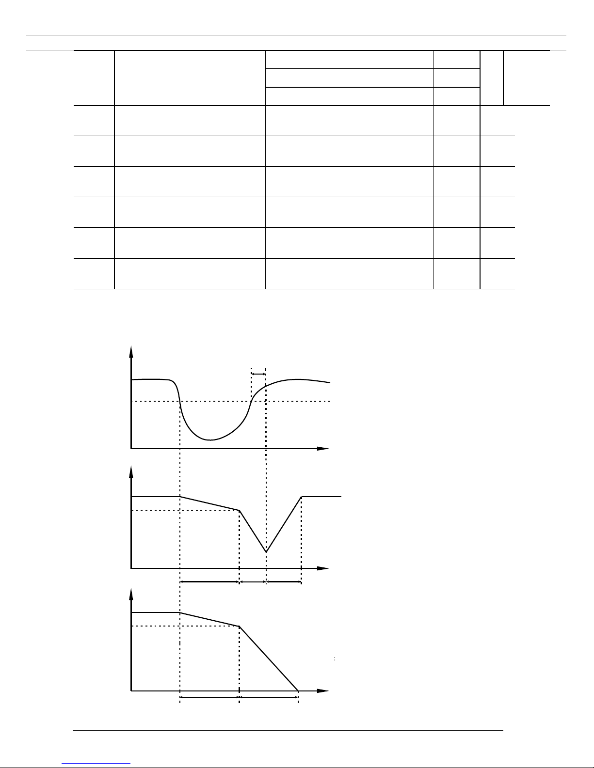
-72-
P9.59
Instantaneous power failure
action selection
Invalid
0
0
☆
DC bus voltage constant control
1
Decelerate to stop
2
P9.60
Instantaneous power failure
resuming voltage
85.0%~120.0%
85.0%
☆
P9.61
Instantaneous power failure voltage
judging time
0.00s~100.00s
0.50s
☆
P9.62
Instantaneous power failure
action DC bus voltage
60.0%~85.0% (Standard DC bus
voltage
)
80.0%
☆
P9.71
Instantaneous power failure gain
Kp
0~100
40
☆
P9.72
Instantaneous power failure
integral coefficient Ki
0~100
30
☆
P9.73
Instantaneous power failure
deceleration time
0~300.0s
20.0s
☆
Upon instantaneous power failure or sudden voltage dip, the DC bus voltage of the inverter reduces.
This function enables the inverter to compensate the DC bus voltage reduction with the load
feedback energy by reducing the output frequency so as to keep the inverter running continuously.
• If P9.59 = 1, once the bus
voltage resumes to normal,
the inverter accelerates to
the set frequency.
• If P9.59 = 2, upon
instantaneous power failure
or sudden voltage dip, the
inverter will continue
decelerating until 0Hz, stop
and wait for next start
command. This function is
to ensure motor will not
coast to stop at power
failure or sudden voltage
dip. When load inertia is
high, coast to stop will take
too much time. In addition,
coast to stop can easily
cause the inverter over-
current or overload.
Bus
voltage
t
t
Running
Frequency
t
P9.62
Running
Frequency
(P9.59=1 :
)
P9.60
(P9.59=2) :
P9.61
Deceleration
time 3
Deceleration
time 4
Acceleration
3
4
P9.60
-73-
P9.63
Protection upon load becoming
0
Disabled
0
0
☆
Enabled
1
P9.64
Detection level of load
becoming 0
0.0%~100.0% (motor rated
current)
10.0%
☆
P9.65
Detection time of load becoming
0
0.0s~60.0s
1.0s
☆
If protection upon load becoming 0 is enabled, when the output current of the inverter is lower than
the detection level (P9.64) and the lasting time exceeds the detection time (P9.65), the output
frequency of the inverter automatically declines to 7% of the rated frequency. During the protection,
the inverter automatically accelerates to the set frequency if the load resumes to normal.
P9.67
Over-speed detection value
0.0%~50.0% (maximum
frequency)
20.0%
☆
P9.68
Over-speed detection time
0.0s~60.0s
1.0s
☆
This function is valid only when the inverter runs in the FVC mode.
If the actual motor rotational speed detected by the inverter exceeds the maximum frequency and
the excessive value is greater than the value of P9.67 and the lasting time exceeds the value of
P9.68, the inverter reports 43=E.oSF and acts according to the selected fault protection action.
If the over-speed detection time is 0.0s, the over-speed detection function is disabled.
P9.69
Detection value of too large
speed deviation
0.0%~50.0% (maximum
frequency)
20.0%
☆
P9.70
Detection time of too large
speed deviation
0.0s~60.0s
5.0s
☆
This function is valid only when the Inverter runs in the FVC mode.
If the inverter detects the deviation between the actual motor rotational speed detected by the
inverter and the set frequency is greater than the value of P9.69 and the lasting time exceeds the
value of P9.70, the inverter reports 42=E.Sdl and according to the selected fault protection action.
If P9.70 (Detection time of too large speed deviation) is 0.0s, this function is disabled.

-74-
4.12 PID functions: PA.00-PA.28
PID control is a general process control method. By performing proportional, integral and differential
operations on the difference between the feedback signal and the target signal, it adjusts the output
frequency and constitutes a feedback system to stabilize the controlled counter around the target value.
It is applied to process control such as flow control, pressure control and temperature control. The
following figure shows the principle block diagram of PID control.
Code
Description
Setting range
Def
Res
PA.00
PI
D setting source
PA.01 setting
0
0
☆
AI1
1
AI2 2 AI3
3
Reserved
4
Communication setting
5
Multi-speed
6
PA.01
PID digital setting
0.0%~100.0%
50.0%
☆
The PID setting is a relative value and ranges from 0.0% to 100.0%. The PID feedback is also a
relative value. The purpose of PID control is to make the PID setting and PID feedback equal.
PA.02
PID
feedback source
AI1
0
0
☆
AI2 1 AI3
2
Reserved
3
Communication setting
4
AI1 5 AI1+AI2
6
MAX (|AI1|, |AI2|)
7
MIN (|AI1|, |AI2|)
8
This parameter is used to select the feedback signal channel of process PID. The PID feedback is a
relative value and ranges from 0.0% to 100.0%.
PA.03
PID action direction
Forward action
0
0
☆
Reverse action
1
0: Forward action
+
-
Target
Feedback
PID
output
P
1
Td*s+1
Ti
S
1
1

-75-
When the feedback value is smaller than the PID setting, the inverter's output frequency rises. For
example, the winding tension control requires forward PID action.
1: Reverse action
When the feedback value is smaller than the PID setting, the inverter's output frequency reduces.
For example, the unwinding tension control requires reverse PID action.
Note that this function is influenced by the DI function 35 "Reverse PID action direction"
PA.04
PID feedback range
0~65535
1000
☆
This parameter is a non-dimensional unit. It is used for PID setting display (d0.15) and PID
feedback display (d0.16).
Relative value 100% of PID setting feedback corresponds to the value of PA.04. If PA.04 is set to
2000 and PID setting is 100.0%, the PID setting display (d0.15) is 2000.
PA.05
Proportional gain K
p1
0.0~100.0
20.0
☆
PA.06
Integral time Ti
1
0.01s~10.00s
2.00s
☆
PA.07
Differential time Td
1
0.00~10.000
0.000s
☆
Proportional gain Kp1:
It decides the regulating intensity of the PID regulator. The higher the
K
p1
is, the larger the
regulating intensity is. The value 100.0 indicates when the deviation between PID feedback and PID
setting is 100.0%, the adjustment amplitude of the PID regulator on the output frequency reference
is the maximum frequency.
Integral time Ti1:
It decides the integral regulating intensity. The shorter the integral time is, the larger the regulating
intensity is. When the deviation between PID feedback and PID setting is 100.0%, the integral
regulator performs continuous adjustment for the time set in PA. 06. Then the adjustment amplitude
reaches the maximum frequency.
Differential time Td1:
It decides the regulating intensity of the PID regulator on the deviation change. The longer the
differential time is, the larger the regulating intensity is. Differential time is the time within which
the feedback value change reaches 100.0%, and then the adjustment amplitude reaches the
maximum frequency.
PA.08
Cut-off frequency of PID
reverse rotation
0.00~ maximum frequency
2.00Hz
☆
In some situations, only when the PID output frequency is a negative value (Inverter reverse
rotation), PID setting and PID feedback can be equal. However, too high reverse rotation frequency
is prohibited in some applications, and PA.08 is used to determine the reverse rotation frequency
upper limit.
PA.09
PID deviation limit
0.0%~100.0%
0.0%
☆
If the deviation between PID feedback and PID setting is smaller than the value of PA.09, PID
control stops. The small deviation between PID feedback and PID setting will make the output
frequency stabilize, effective for some closed-loop control applications.
PA.10
PID differential limit
0.00%~100.00%
0.10%
☆
It is used to set the PID differential output range. In PID control, the differential operation may
easily cause system oscillation. Thus, the PID differential regulation is restricted to a small range.
PA.11
PID setting change time
0.00s~650.00s
0.00s
☆
The PID setting change time indicates the time required for PID setting changing from 0.0% to
100.0%. The PID setting changes linearly according to the change time, reducing the impact
caused by sudden setting change on the system.
PA.12
PID feedback filter time
0.00s~60.00s
0.00s
☆
PA.13
PID output filter time
0.00s~60.00s
0.00s
☆

-76-
PA.12 is used to filter the PID feedback, helping to reduce interference on the feedback but
slowing the response of the process closed-loop system.
PA.13 is used to filter the PID output frequency, helping to weaken sudden change of the
Inverter output frequency but slowing the response of the process closed-loop system.
PA.14
Reserved
- - -
PA.15
Proportional gain K
p2
0.0~100.0
20.0
☆
PA.16
Integral time Ti
2
0.01s~10.00s
2.00s
☆
PA.17
Differential timeTd
2
0.00~10.000
0.000
s
☆
PA.18
PID parameter switchover
condition
No switchover
0
0
☆
Switchover via DI
1
Automatic switchover based
on deviation
2
PA.19
PID parameter switchover
deviation 1
0.0%~PA.20
20.0% ☆ PA.20
PID parameter switchover
deviation 2
PA.19~100.0%
80.0%
☆
In some applications, PID parameters switchover is required when one group of PID parameters
cannot satisfy the requirement of the whole running process.
These parameters are used for switchover between two groups of PID parameters. Regulator
parameters PA.15 to PA.17 are set in the same way as PA.05 to PA.07.
The switchover can be implemented either via a DI terminal or automatically implemented based on
the deviation.
If you select switchover via a DI terminal, the DI must be allocated with function 43 "PID
parameter switchover". If the DI is OFF, group 1 (PA.05 to PA.07) is selected. If the DI is ON,
group 2 (PA.15 to PA.17) is selected.
If you select automatic switchover, when the absolute value of the deviation between PID feedback
and PID setting is smaller than the value of PA.19, group 1 is selected. When the absolute value of
the deviation between PID feedback and PID setting is higher than the value of PA.20, group 2 is
selected. When the deviation is between PA.19 and PA.20, the PID parameters are the linear
interpolated value of the two groups of parameter values.
PA.21
PI
D initial value
0.0%~100.0%
0.0%
☆
PA.19
PA.20
PID
deviation
Parameters
PA.05、
PA.06、
PA.07
PA.15
、
PA.16
、
PA.17

-77-
PA.22
PID initial value holding
time
0.00s~650.00s
0.00s
☆
When the Inverter starts up, the PID starts closed-loop algorithm only after the PID output is fixed
to the PID initial value (PA.21) and lasts the time set in PA.22.
This function is used to limit the deviation between two PID outputs (2 ms per PID output) to
suppress the rapid change of PID output and stabilize the running of the Inverter.
PA.23
Maximum deviation between
two PID outputs in forward
direction
0.00%~100.00%
1.00%
☆
PA.24
Maximum deviation between
two PID outputs in reverse
direction
0.00%~100.00%
1.00%
☆
PA.23 and PA.24 respectively correspond to the maximum absolute value of the output deviation in
forward direction and in reverse direction.
PA.25
PID integral property
One’s place
Integral separation
00
☆
Invalid
0
Valid
1
Ten’s place
Selection when the output
reaches the limit
Continue integral
0
Stop integral
1
PA.26
Detection value of PID
feedback loss
Not judging feedback loss
0.0%
0
.
0%
☆
0.1%~100.0%
0.1%
PA.27
Detection time of PID
feedback loss
0.0s~20.0s
0s
☆
These parameters are used to judge whether PID feedback is lost.
If the PID feedback is smaller than the value of PA.26 and the lasting time exceeds the value of
PA.27, the inverter reports 31=E.PID and acts according to the selected fault protection action.
PA.28
PID operation at stop
No PID operation
0
0
☆
PID operation continues
1
It is used to select whether to continue PID operation in the state of stop. Generally, the PID
operation stops when the inverter stops.
Output
Frequency
t
PA.21
PA.22

-78-
4.13 Swing Frequency, Fixed Length and Count: PB.00-PB.09
The swing frequency function is applied to the textile and chemical fiber fields and the applications
where traversing and winding functions are required.
The swing frequency function indicates that the output frequency of the inverter swings up and down
with the set frequency as the center. The trace of running frequency at the time axis is shown in the
following figure.
The swing amplitude is set in PB.00 and PB.01. When PB.01 is set to 0, the swing amplitude is 0 and
the swing frequency does not take effect.
Code
Description
Setting range
Def
Res
PB.00
Swing frequency relativity
setting
Relative to the central frequency
0
0
☆
Relative to the maximum frequency
1
0: Relative to the central frequency (P0.07 frequency source selection)
It is variable swing amplitude system. The swing amplitude varies with the central frequency (set
frequency).
1: Relative to the maximum frequency (P0.10 maximum output frequency)
It is fixed swing amplitude system. The swing amplitude is fixed.
PB.01
Swing frequency amplitude
0.0%~100.0%
0
.
0%
☆
PB.02
Swing jump frequency
amplitude
0.0%~50.0%
0
.
0%
☆
These parameters are used to determine the swing amplitude and jump frequency amplitude. The
swing frequency is limited by the swing frequency upper limit and swing frequency lower limit.
• If relative to the central frequency (PB.00 = 0), the actual swing amplitude AW is the calculation
result of P0.07 (Frequency source selection) multiplied by PB.01.
• If relative to the maximum frequency (PB.00 = 1), the actual swing amplitude AW is the
calculation result of P0.10 (Maximum frequency) multiplied by PB.01.
Swing jump frequency = Swing amplitude AW x PB.02 (Swing jump frequency amplitude). Swing
jump frequency is a percentage related to PB.01.
• If relative to the central frequency (PB.00 = 0), the swing jump frequency is a variable value.
Output
Frequency
Hz
Fset
运行命令
accelerate by
acceleration time
Swing cycle
Triangular
Rising time
Decelerate by
deceleration time
time
t
+Aw
-Aw
Pb.00=1
:
Aw=Fmax*Pb.01
=Aw*Pb.02
Aw=Fset*Pb.01
Pb.00=0
:
Swing upper limit
Swing lower limit
Set frequency

-79-
• If relative to the maximum frequency (PB.00 = 1), the swing jump frequency is a fixed value. The
swing frequency is limited by the frequency upper limit and frequency lower limit.
PB.03
Swing frequency cycle
0.0s~3000.0s
10
.
0s
☆
PB.04
Triangular wave rising time
coefficient
0.0%~100.0%
50
.
0%
☆
PB.03 specifies the time of a complete swing frequency cycle.
PB.04 specifies the time percentage of triangular wave rising time to PB.03 (Swing frequency
cycle).
• Triangular wave rising time = PB.03 (Swing frequency cycle) x PB.04 (Triangular wave rising
time coefficient, unit: s)
• Triangular wave falling time = PB.03 (Swing frequency cycle) x (1 - PB.04 Triangular wave rising
time coefficient, unit: s)
PB.05
Set length
0m~65535m
1000m
☆
PB.06
Actual length
0m~65535m
0m
☆
PB.07
Number of pulses per meter
0.1~6553.5
100.0
☆
The preceding parameters are used for fixed length control.
The length information is collected by DI terminals. PB.06 (Actual length) is calculated by dividing
the number of pulses collected by the DI terminal by PB.07 (Number of pulses each meter).
When the actual length PB.06 exceeds the set length in PB.05, the DO terminal allocated with
function 10 (Length reached) becomes ON.
During the fixed length control, the length reset operation can be performed via the DI terminal
allocated with function 28. For details, see the descriptions of P4.00 to P4.09.
Allocate corresponding DI terminal with function 27 (Length count input) in applications. If the
pulse frequency is high, DI5 must be used.
PB.08
Set count value
1~65535
1000
☆
PB.09
Designated count value
1~65535
1000
☆
The count value needs to be collected by DI terminal. Allocate the corresponding DI terminal with
function 25 (Counter input) in applications. If the pulse frequency is high, DI5 must be used.
When the count value reaches the set count value (PB.08), the DO terminal allocated with function
8 (Set count value reached) becomes ON. Then the counter stops counting.
When the counting value reaches the designated counting value (PB.09), the DO terminal allocated
with function 9 (Designated count value reached) becomes ON. Then the counter continues to count
until the set count value is reached.
PB.09 should be equal to or smaller than PB.08.

-80-
4.14 Multi-speed and simple PLC: PC.00-PC.51
DLA1 multi-speed has many functions. Besides multi-speed, it can be used as the setting source of the
V/F separated voltage source and setting source of process PID.
Code
Description
Setting range
Def
Res
PC.00
Multi-speed 0
-100.0%~100.0%
0
.
0%
☆
PC.01
Multi-speed 1
-100.0%~100.0%
0
.
0%
☆
PC.02
Multi-speed 2
-100.0%~100.0%
0
.
0%
☆
PC.03
Multi-speed 3
-100.0%~100.0%
0
.
0%
☆
PC.04
Multi-speed 4
-100.0%~100.0%
0
.
0%
☆
PC.05
Multi-speed 5
-100.0%~100.0%
0
.
0%
☆
PC.06
Multi-speed 6
-100.0%~100.0%
0
.
0%
☆
PC.07
Multi-speed 7
-100.0%~100.0%
0
.
0%
☆
PC.08
Multi-speed 8
-100.0%~100.0%
0
.
0%
☆
PC.09
Multi-speed 9
-100.0%~100.0%
0
.
0%
☆
PC.10
Multi-speed 10
-100.0%~100.0%
0
.
0%
☆
PC.11
Multi-speed 11
-100.0%~100.0%
0
.
0%
☆
PC.12
Multi-speed 12
-100.0%~100.0%
0
.
0%
☆
PC.13
Multi-speed 13
-100.0%~100.0%
0
.
0%
☆
PC.14
Multi-speed 14
-100.0%~100.0%
0
.
0%
☆
PC.15
Multi-speed 15
-100.0%~100.0%
0
.
0%
☆
Multi-speed can be the setting source of frequency, V/F separated voltage and process PID. The
multi-speed is relative value and ranges from -100.0% to 100.0%.
As frequency source, it is a percentage relative to the maximum frequency. As V/F separated voltage
source, it is a percentage relative to the motor rated voltage. As process PID setting source, it does not
require conversion.
Multi-speed can be switched over based on different states of DI terminals. For details, see the
descriptions of group P4.
PC.16
Simple PLC running mode
Stop after one cycle
0
0
☆
Keep final values after one cycle
1
Repeat after one cycle
2

-81-
0: Stop after one cycle
The inverter stops after running one cycle, and will not start up until receiving another command.
1: Keep final values after one cycle
The Inverter keeps the final running frequency and direction after running one cycle.
2: Repeat after one cycle
The inverter automatically starts another cycle after running one cycle, and will not stop until
receiving the stop command.
Simple PLC can be either the frequency source or V/F separated voltage source.
When simple PLC is used as the frequency source, whether parameter values of PC.00 to PC.15 are
positive or negative determines the running direction. If the parameter values are negative, it indicates
that the inverter runs in reverse direction.
PC.17
Simple PLC retentive
selection
One’s place
Upon power off
00
☆
No
0
Yes
1
Ten’s place
Upon stop
No
0 Yes
1
The inverter can memorize the PLC running section and running frequency upon power off and will
continue to run from the memorized section after it is powered on again. If set to 0, the inverter
restarts the PLC process after it is powered on again.
The inverter can also record the PLC running section and running frequency upon stop and will
continue to run from the recorded moment after it starts up again. If the ten's place is set to 0, the
inverter restarts the PLC process after it starts up again.
PC.18
Simple PLC section 0 running time
0.0s (h) ~6553.5s (h)
0.0s (h)
☆
running
direction
PC.00
PC.21
PC.01
PC.18
PC.20
PC.23
PC.02
PC.14
PC.15
250ms pulse
time
t
DO
or
RELAY
Output
PC.19

-82-
PC.19
Simple PLC section 0 running
acceleration/deceleration time
0~3
0
☆
PC.20
Simple PLC section 1 running time
0.0s (h) ~6553.5s (h)
0.0s (h)
☆
PC.21
Simple PLC section 1 running
acceleration/deceleration time
0~3
0
☆
PC.22
Simple PLC section 2 running time
0.0s (h) ~6553.5s (h)
0.0s (h)
☆
PC.23
Simple PLC section 2 running
acceleration/deceleration time
0~3
0
☆
PC.24
Simple PLC section 3 running time
0.0s (h) ~6553.5s (h)
0.0s (h)
☆
PC.25
Simple PLC section 3 running
acceleration/deceleration time
0~3
0
☆
PC.26
Simple PLC section 4 running time
0.0s (h) ~6553.5s (h)
0.0s (h)
☆
PC.27
Simple PLC section 4 running
acceleration/deceleration time
0~3
0
☆
PC.28
Simple PLC section 5 running time
0.0s (h) ~6553.5s (h)
0.0s (h)
☆
PC.29
Simple PLC section 5 running
acceleration/deceleration time
0~3
0
☆
PC.30
Simple PLC section 6 running time
0.0s (h) ~6553.5s (h)
0.0s (h)
☆
PC.31
Simple PLC section 6 running
acceleration/deceleration time
0~3
0
☆
PC.32
Simple PLC section 7 running time
0.0s (h) ~6553.5s (h)
0.0s (h)
☆
PC.33
Simple PLC section 7 running
acceleration/deceleration time
0~3
0
☆
PC.34
Simple PLC section 8 running time
0.0s (h) ~6553.5s (h)
0.0s (h)
☆
PC.35
Simple PLC section 8 running
acceleration/deceleration time
0~3
0
☆
PC.36
Simple PLC section 9 running time
0.0s (h) ~6553.5s (h)
0.0s (h)
☆
PC.37
Simple PLC section 9 running
acceleration/deceleration time
0~3
0
☆
PC.38
Simple PLC section 10 running time
0.0s (h) ~6553.5s (h)
0.0s (h)
☆
PC.39
Simple PLC section 10 running
acceleration/deceleration time
0~3
0
☆
PC.40
Simple PLC section 11 running time
0.0s (h) ~6553.5s (h)
0.0s (h)
☆
PC.41
Simple PLC section 11 running
acceleration/deceleration time
0~3
0
☆
PC.42
Simple PLC section 12 running time
0.0s (h) ~6553.5s (h)
0.0s (h)
☆
PC.43
Simple PLC section 12 running
acceleration/deceleration time
0~3
0
☆
PC.44
Simple PLC section 13 running time
0.0s (h) ~6553.5s (h)
0.0s (h)
☆
PC.45
Simple PLC section 13 running
acceleration/deceleration time
0~3
0
☆

-83-
PC.46
Simple PLC section 14 running time
0.0s (h) ~6553.5s (h)
0.0s (h)
☆
PC.47
Simple PLC section 14 running
acceleration/deceleration time
0~3
0
☆
PC.48
Simple PLC section 15 running time
0.0s (h) ~6553.5s (h)
0.0s (h)
☆
PC.49
Simple PLC section 15 running
acceleration/deceleration time
0~3
0
☆
PC.50
Time unit of simple PLC running
s (s)
0
0
☆
h (hour)
1
PC.51
Multi-speed 0 source selection
PC.00 setting
0
0
☆
AI1 1 AI2 2 AI3
3
Pulse setting
4
PID
5
Set by P0.08, modified
via UP/DOWN
6
It determines the setting channel of multi-speed 0.
You can perform convenient switchover between the setting channels. When multi-speed or simple
PLC is used as frequency source, the switchover between two frequency sources can be realized
easily.

-84-
4.15 Communication parameters: PD.00-PD.06
Please refer to DLA1 communication protocol in Chapter 7.
Code
Description
Setting range
Def
Res
PD.00
Bit rate
One’s place
MODBUS
6005
☆
300BPS
0
600BPS
1
1200BPS
2
2400BPS
3
4800BPS
4
9600BPS
5
19200BPS
6
38400BPS
7
57600BPS
8
115200BPS
9
PD.01
Data type
8-N-2
0
0
☆
8-E-1
1
8-O-1
2
8-N-1
3
PD.02
This device address
1-247, 0 is master station address
1
☆
PD.03
Response delay
0ms-20ms
2
☆
PD.04
Communication
over-time
0.0 (invalid), 0.1s-60.0s
0.0
☆
PD.05
Data transfer format
One’s place
MODBUS
30
☆
Non-standard MODBUS protocol
0
Standard MODBUS protocol
1
PD.06
Current resolution
0.01A
0
0
☆
0.1A
1

-85-
4.16 Function code management: PP.00-PP.04
Code
Description
Setting range
Def
Res
PP.00
User password
0~65535
0
☆
If it is set to any non-zero number, the password protection function is enabled. After a password
has been set and taken effect, you must enter the correct password in order to enter the menu. If
the entered password is incorrect you cannot view or modify parameters.
If PP.00 is set to 00000, the previously set user password is cleared, and the password protection
function is disabled.
PP.01
Parameter initialization
No operation
0
0
★
Restore factory settings except motor
parameters
1
Clear records
2
Backup current parameters to control
board memory
4
Use control board memory to restore
parameters
501
PP.02
Inverter parameter
display property
One’s place
Group d display selection
11
★
No display
0
Display
1
Ten’s place
Group B display selection
No display
0
Display
1
PP.03
User’s parameter display
property
One’s place
Display selection
00
☆
No display
0 Display
1
Ten’s place
Special parameter display
No display
0
Display
1
PP.04
Parameter modification
property
Modifiable
0
0
Not modifiable
1
It is used to set whether the parameters are modifiable to avoid mal-function. If it is set to 0, all
parameters are modifiable. If it is set to 1, all parameters can only be viewed.

-86-
4.17 Torque control parameters: B0.00-B0.08
Code
Description
Setting range
Def
Res
B0.00
Speed/Torque control selection
Speed control
0
0
★
Torque control
1
DLA1 provides DI terminals with two torque related functions, function 29 (Torque control
prohibited) and function 46 (Speed control/Torque control switchover). The two DI terminals need
to be used together with B0.00 to implement speed control/torque control switchover.
If the DI terminal allocated with function 46 (Speed control/Torque control switchover) is OFF,
the control mode is determined by B0.00. If the DI terminal allocated with function 46 is ON, the
control mode is reverse to the value of B0.00.
However, if the DI terminal with function 29 (Torque control prohibited) is ON, the Inverter is
fixed to run in the speed control mode.
B0.01
Torque setting source selection
Digital setting (B0.03)
0
0
★
AI1 1 AI2 2 AI3
3
Reserved
4
Communication setting
5
MIN (AI1, AI2)
6
MAX (AI1, AI2)
7
B0.03
Torque digital setting
-200.0%~200.0%
150%
☆
B0.01 is used to set the torque setting source. There are a total of eight torque setting sources.
The torque setting is a relative value. 100.0% corresponds to the Inverter's rated torque. The
setting range is -200.0% to 200.0%, indicating the inverter's maximum torque is twice of the
inverter's rated torque.
If the torque setting is positive, the inverter rotates in forward direction. If the torque setting is
negative, the inverter rotates in reverse direction.
B0.05
Torque control forward
maximum frequency
0.00Hz~ maximum frequency
50
.
00Hz
☆
B0.06
Torque control reverse
maximum frequency
0.00Hz~ maximum frequency
50
.
00Hz
☆
B0.07
Acceleration time in torque
control mode
0.00s~65000s
0.00s
☆
B0.08
Deceleration time in torque
control mode
0.00s~65000s
0.00s
☆

-87-
4.18 Control optimization parameters: B5.00-B5.09
Code
Description
Setting range
Def
Res
B5.00
DPWM switchover
frequency upper limit
0.00Hz~15.00Hz
12.00Hz
☆
This parameter is valid only for V/F control.
It is used to determine the wave modulation mode in V/F control of asynchronous motor. If the
frequency is lower than the value of this parameter, the waveform is 7 -segment continuous
modulation. If the frequency is higher than the value of this parameter, the waveform is 5-segment
intermittent modulation.
The 7-segment continuous modulation causes more loss to switches of the Inverter but smaller
current ripple. The 5-segment intermittent modulation causes less loss to switches of the Inverter
but larger current ripple. This may lead to motor running instability at high frequency. Do not
modify this parameter generally.
For instability of V/F control, refer to parameter P3.11. For loss to Inverter and temperature rise,
refer to parameter P0.15.
B5.01
PWM modulation mode
Asynchronous modulation
0
0
☆
Synchronous modulation
1
This parameter is valid only for V/F control.
Synchronous modulation indicates that the carrier frequency varies linearly with the change of the
output frequency, ensuring that the ratio of carrier frequency to output frequency remains
unchanged. Synchronous modulation is generally used at high output frequency, which helps
improve the output voltage quality.
At low output frequency (100 Hz or lower), synchronous modulation is not required. This is
because asynchronous modulation is preferred when the ratio of carrier frequency to output
frequency is high.
Synchronous modulation takes effect only when the running frequency is higher than 85 Hz. If the
frequency is lower than 85 Hz, asynchronous modulation is always used.
B5.02
Dead zone compensation
mode selection
No compensation
0
1
☆
Compensation mode 1
1
Generally, you need not modify this parameter. Try to use a different compensation mode only
when there is special requirement on the output voltage waveform quality or oscillation occurs on
the motor.
B5.03
Random PWM depth
Random PWM invalid
0
0
☆
Random PWM depth selection
1~10
The setting of random PWM depth can make the shrill motor noise softer and reduce the
electromagnetic interference. If this parameter is set to 0, random PWM is invalid.
B5.04
Rapid current limit
Disabled
0
1
☆
Enabled
1
The rapid current limit function can reduce the inverter's overcurrent faults at maximum,
guaranteeing uninterrupted running of the inverter.
However, long-time rapid current limit may cause the inverter to overheat, which is not allowed. If
so, the inverter will output 40=E.CbC, indicating the inverter is overloaded and needs to stop.

-88-
B5.05
Current detection
compensation
0~100
5
☆
It is used to set the Inverter current detection compensation. Too large value may lead to
deterioration of control performance. Do not modify it generally.
B5.06
Under voltage threshold
210V ~ 420V
350V
☆
It is used to set the under voltage threshold of 9=E.LU. The under voltage threshold 100% of the
inverter of different voltage classes corresponds to different nominal values, as listed in the
following table.
Voltage Class
Nominal Value of Under voltage threshold
Single-phase 220 V
200 V
Three-phase 220 V
200 V
Three-phase 380 V
350 V
Three-phase 480 V
450 V
Three-phase 690 V
650 V
B5.07
SVC optimization mode
selection
Optimization mode 1
1
1
☆
Optimization mode2
2
1: Optimization mode 1
It is used when the requirement on torque control linearity is high.
2: Optimization mode 2
It is used for the requirement on speed stability is high.
B5.08
Dead-zone time adjustment
100%~200%
150%
☆
It is only valid for 1140 V voltage class.
You can modify the value of this parameter to improve the voltage utilization rate. Too small value
may system instability. Do not modify it generally.
B5.09
Overvoltage threshold
200.0V~2500.0V
810.0V
☆
It is used to set the overvoltage threshold of the inverter. The default values of different voltage
classes are listed in the following table.
Voltage Class
Default Overvoltage Threshold
Single-phase 220 V
400.0 V
Three-phase 220 V
400.0 V
Three-phase 380 V
810.0 V
Three-phase 480 V
890.0 V
Three-phase 690 V
1300.0 V

-89-
5 Fault and solutions
5.1 Alarms and solutions
DLA1 provides a total of 51 fault information and protective functions. After a fault occurs, the inverter
implements the protection function, and displays the fault code on the keyboard (if the keyboard is
available).
Before contacting DORNA for technical support, you can first determine the fault type, analyze the
causes, and perform troubleshooting according to the following tables. If the fault cannot be rectified,
contact the official distributor or DORNA directly.
22=E.HArd is the inverter hardware over-current or over-voltage signal. In most situations, hardware
over-voltage fault causes 22=E.HArd.
Fault
Display
Possible Causes
Solutions
1=E.IGbt
1: The output circuit is grounded
or short circuited.
2: The connecting cable of the
motor is too long.
3: The module overheats.
4: Internal connections is loose.
5: Main control board is faulty.
6: The power board is faulty.
7: IGBT is faulty.
1: Eliminate external faults.
2: Install a reactor or an output filter.
3: Check the air filter and the fan.
4: Connect all cables properly.
5: Contact the distributor.
2=E.oCAC
1: The output circuit is grounded
or short circuited.
2: Motor auto-tuning is not
performed.
3: The acceleration time is too
short.
4: Manual torque boost or V/F
curve is not appropriate.
5: The voltage is too low.
6: The startup operation is
performed on the rotating motor.
7: A sudden load is added during
acceleration.
8: The Inverter model is of too
small power class.
1: Eliminate external faults.
2: Perform the motor auto-tuning.
3: Increase the acceleration time.
4: Adjust the manual torque boost or V/F
curve.
5: Adjust the voltage to normal range.
6: Select rotational speed tracking restart
or start the motor after it stops.
7: Remove the added load.
8: Select an Inverter of higher power
class.
3=E.oCdE
1: The output circuit is grounded
or short circuited.
2: Motor auto-tuning is not
performed.
3: The deceleration time is too
short.
4: The voltage is too low.
5: A sudden load is added during
deceleration.
6: The braking unit and braking
resistor are not installed.
1: Eliminate external faults.
2: Perform the motor auto-tuning.
3: Increase the deceleration time.
4: Adjust the voltage to normal range.
5: Remove the added load.
6: Install the braking unit and braking
resistor.

-90-
Fault Name
Display
Possible Causes
Solutions
Constant speed
over current
4=E.oCCo
1: The output circuit is grounded
or short circuited.
2: Motor auto-tuning is not
performed.
3: The voltage is too low.
4: A sudden load is added during
operation.
5: The Inverter model is of too
small power class.
1: Eliminate external faults.
2: Perform the motor autotuning.
3: Adjust the voltage to
normal range.
4: Remove the added load. 5:
Select an Inverter of higher
power class.
Acceleration
over voltage
5=E.oUAC
1: The input voltage is too high. 2:
An external force drives the motor
during acceleration.
3: The acceleration time is too
short.
4: The braking unit and braking
resistor are not installed.
1: Adjust the voltage to
normal range.
2: Cancel the external force
or install a braking resistor.
3: Increase the acceleration
time.
4: Install the braking unit and
braking resistor.
Deceleration
over voltage
6=E.oUdE
1: The input voltage is too high. 2:
An external force drives the motor
during deceleration.
3: The deceleration time is too
short.
4: The braking unit and braking
resistor are not installed.
1: Adjust the voltage to
normal range.
2: Cancel the external force
or install the braking resistor. 3:
Increase the deceleration time.
4: Install the braking unit and
braking resistor.
Constant speed
over voltage
7=E.oUCo
1: The input voltage is too high.
2: An external force drives the
motor during deceleration.
1: Adjust the voltage to
normal range.
2: Cancel the external force
or install the braking resistor.
Control power
fault
8=E.CPF
The input voltage is not within the
allowable range.
Adjust the input voltage to the
allowable range.
Under voltage
9=E.LU
1: Instantaneous power failure
occurs on the input power supply. 2:
The Inverter's input voltage is not
within the allowable range.
3: The bus voltage is abnormal.
4: The rectifier bridge and buffer
resistor are faulty.
5: The drive board is faulty.
6: The main control board is
faulty.
1: Reset the fault.
2: Adjust the voltage to
normal range.
3: Contact the official
distributor or DORNA directly.
Inverter overload
10=E.oL1
1: The load is too heavy or lockedrotor occurs on the motor.
2: The Inverter model is of too
small power class.
1: Reduce the load and check
the motor and mechanical
condition.
2: Select an Inverter of higher
power class.

-91-
Fault Name
Display
Possible Causes
Solutions
Motor overload
11=E.oLt
1: F9-01 is set improperly.
2: The load is too heavy or
locked- rotor occurs on the motor.
3: The Inverter model is of too
small power class.
1: Set F9-01 correctly.
2: Reduce the load and check
the motor and the mechanical
condition.
3: Select an Inverter of higher
power class.
Input phase loss
12=E.ILF
1: The three-phase power input is
abnormal.
2: The drive board is faulty.
3: The lightening board is faulty.
4: The main control board is
faulty.
1: Eliminate external faults.
2: Contact the official
distributor or DORNA directly.
Output phase
loss
13=E.oLF
1: The cable connecting the
Inverter and the motor is faulty.
2: The Inverter's three-phase
outputs are unbalanced when the
motor is running.
3: The drive board is faulty.
4: The module is faulty.
1: Eliminate external faults.
2: Check whether the motor
three-phase winding is normal.
3: Contact the official
distributor or DORNA directly.
Module overheat
14=E.oH1
1: The ambient temperature is too
high.
2: The air filter is blocked.
3: The fan is damaged.
4: The thermally sensitive resistor
of the module is damaged.
5: The inverter module is
damaged.
1: Lower the ambient
temperature.
2: Clean the air filter.
3: Replace the damaged fan.
4: Replace the damaged
thermally sensitive resistor.
5: Replace the inverter
module.
External
equipment fault
15=E.EIoF
1: External fault signal is input
via DI.
2: External fault signal is input
via virtual I/O.
Reset the operation.
Communication
fault
16=E.CoF1
1: The host computer is in
abnormal state.
2: The communication cable is
faulty.
3: P0.28 is set improperly.
4: The communication
parameters in group FD are set
1: Check the cabling of host
computer.
2: Check the communication
cabling.
3: Set P0.28 correctly.
4: Set the communication
parameters properly.
Contactor fault
17=E.rECF
1: The drive board and power
supply are faulty.
2: The contactor is faulty.
1: Replace the faulty drive
board or power supply board.
2: Replace the faulty
contactor.

-92-
Fault Name
Display
Possible Causes
Solutions
Current
detection fault
18=E.HALL
1: The HALL device is faulty. 2:
The drive board is faulty.
1: Replace the faulty HALL
device.
2: Replace the faulty drive
board.
Motor autotuning fault
19=E.tUnE
1: The motor parameters are not
set according to the nameplate.
2: The motor auto-tuning times
out.
1: Set the motor parameters
according to the nameplate
properly.
2: Check the cable connecting
the Inverter and the motor.
Encoder fault
20=E.PG1
1: The encoder type is incorrect.
2: The cable connection of the
encoder is incorrect.
3: The encoder is damaged.
4: The PG card is faulty.
1: Set the encoder type
correctly based on the actual
situation.
2: Eliminate external faults.
3: Replace the damaged
encoder.
4: Replace the faulty PG card.
EEPROM readwrite fault
21=E.EEP
The EEPROM chip is damaged.
Replace the main control board.
Inverter
hardware fault
22=E.HArd
1: Overvoltage exists.
2: Overcurrent exists.
1: Handle based on
overvoltage.
2: Handle based on
overcurrent.
Short circuit to
ground
23=E.SHot
The motor is short circuited to the
ground.
Replace the cable or motor.
Accumulative
running time
reached
26=E.ArA
The accumulative running time
reaches the setting value.
Clear the record through the
parameter initialization
function.
User-defined
fault 1
27=E.USt1
1: The user-defined fault 1 signal
is input via DI.
2: User-defined fault 1 signal is
input via virtual I/O.
Reset the operation.
User-defined
fault 2
28=E.Ust2
1: The user-defined fault 2 signal
is input via DI.
2: The user-defined fault 2 signal
is input via virtual I/O.
Reset the operation.
Accumulative
power-on time
reached
29=E.APA
The accumulative power-on time
reaches the setting value.
Clear the record through the
parameter initialization
function.
Load becoming
0
30=E.ULF
The Inverter running current is
lower than F9-64.
Check that the load is
disconnected or the setting of
F9-64 and F9-65 is correct.
PID feedback
lost during
running
31=E.PID
The PID feedback is lower than the
setting of FA-26.
Check the PID feedback signal
or set FA-26 to a proper value.

-93-
Fault Name
Display
Possible Causes
Solutions
Pulse-by-pulse
current limit
fault
40=E.CbC
1: The load is too heavy or
locked- rotor occurs on the motor.
2: The Inverter model is of too
small power class.
1: Reduce the load and check
the motor and mechanical
condition.
2: Select an Inverter of higher
power class.
Motor
switchover fault
during running
41=E.tSr
Change the selection of the motor
via terminal during running of the
Inverter.
Perform motor switchover after
the Inverter stops.
Too large speed
deviation
42=E.SdL
1: The encoder parameters are set
incorrectly.
2: The motor auto-tuning is not
performed.
3: F9-69 and F9-70 are set
incorrectly.
1: Set the encoder parameters
properly.
2: Perform the motor autotuning.
3: Set F9-69 and F9-70
correctly based on the actual
situation.
Motor overspeed
43=E.oSF
1: The encoder parameters are set
incorrectly.
2: The motor auto-tuning is not
performed.3: F9-69 and F9-70 are
set incorrectly.
1: Set the encoder parameters
properly.
2: Perform the motor autotuning.
3: Set F9-69 and F9-70
correctly based on the actual
situation.
Motor overheat
45=E.oHt
1: The cabling of the temperature
sensor becomes loose.
2: The motor temperature is too
high.
1: Check the temperature
sensor cabling and eliminate
the cabling fault.
2: Lower the carrier
frequency or adopt other heat
radiation measures.
Initial position
fault
51=E.PoSF
The motor parameters are not set
based on the actual situation.
Check that the motor
parameters are set correctly and
whether the setting of rated
current is too small.

-94-
5.2 Other fault and solutions
You may come across the following faults during the use of the inverter. Refer to the following table
for simple fault analysis.
SN
Fault
Possible Causes
Solutions
1
There is no display at
power-on.
1: There is no power supply to the
Inverter or the power input to the
Inverter is too low.
2: The power supply of the switch
on the drive board of the Inverter is
faulty.
3: The rectifier bridge is damaged.
4: The control board or the keyboard
is faulty.
5: The cable connecting the control
board and the drive board and the
keyboard breaks.
1: Check the power supply.
2: Check the bus voltage.
3: Re-connect the 8-core and 28-
core cables.
4: Contact the official distributor
or DORNA directly for technical
support.
2
“DLA1” is displayed
at power-on and then
stop immediately.
1: The cable between the drive
board and the control board is in poor
contact.
2: Related components on the
control board are damaged.
3: The motor or the motor cable is
short circuited to the ground.
4: The HALL device is faulty.
5: The power input to the Inverter is
too low.
1: Re-connect the 8-core and 28core cables.
2: Contact the official distributor
or DORNA directly for technical
support.
3
23=E.SHot is
displayed at poweron.
1: The motor or the motor output
cable is short-circuited to the ground.
2: The Inverter is damaged.
1: Measure the insulation of the
motor and the output cable with a
megger.
2: Contact the official distributor
or DORNA directly for technical
support.
4
The Inverter display
is normal upon
power- on. But
“DLA1” is displayed
after running and
stops immediately.
1: The cooling fan is damaged or
locked-rotor occurs.
2: The external control terminal cable
is short circuited.
1: Replace the damaged fan.
2: Eliminate external fault.
5
14=E.oH1 (module
overheat) fault is
reported frequently.
1: The setting of carrier frequency is
too high.
2: The cooling fan is damaged, or
the air filter is blocked.
3: Components inside the Inverter
are damaged (thermal coupler or
others).
1: Reduce the carrier frequency
(P0.15).
2: Replace the fan and clean the
air filter.
3: Contact the official distributor
or DORNA directly for technical
support.

-95-
Warning:
※ Do not touch any component inside the device within 5 minutes after the (! CHARGE) light is off
after power off, otherwise user is in danger of electric shock.
※ Do not touch the PCB or IGBT without electrostatic protections, otherwise the internal components
can be damaged.
SN
Fault
Possible Causes
Solutions
6
The motor does not
rotate after the
Inverter runs.
1: Check the motor and the motor
cables.
2: The Inverter parameters are set
improperly (motor parameters).
3: The cable between the drive board
and the control board is in poor
contact.
4: The drive board is faulty.
1: Ensure the cable between the
Inverter and the motor is normal.
2: Replace the motor or clear
mechanical faults.
3: Check and re-set motor
parameters.
7
The DI terminals are
disabled.
1: The parameters are set
incorrectly.
2: The external signal is incorrect.
3: The jumper bar across SP and +24
V becomes loose.
4: The control board is faulty.
1: Check and reset the
parameters in group P4.
2: Re-connect the external signal
cables.
3: Re-confirm the jumper bar
across OP and +24 V.
4: Contact the official distributor
or DORNA directly for technical
support.
8
The motor speed is
always low in FVC
mode.
1: The encoder is faulty.
2: The encoder cable is connected
incorrectly or in poor contact.
3: The PG card is faulty.
4: The drive board is faulty.
1: Replace the encoder and
ensure the cabling is proper.
2: Replace the PG card.
3: Contact the official distributor
or DORNA directly for technical
support.
9
The Inverter reports
overcurrent and
overvoltage
frequently.
1: The motor parameters are set
improperly.
2: The acceleration/deceleration
time is improper.
3: The load fluctuates.
1: Re-set motor parameters or reperform the motor autotuning.
2: Set proper acceleration/
deceleration time.
3: Contact the official distributor
or DORNA directly for technical
support.

-96-
6 Repair and maintenance
6.1 Routine maintenance
The influence of the ambient temperature, humidity, dust and vibration will cause the aging of the
devices in the Inverter, which may cause potential faults or reduce the service life of the Inverter.
Therefore, it is necessary to carry out routine and periodic maintenance.
Routine maintenance involves checking:
Item
Details
Measures
Terminal screws
Are they loose?
Tighten the screws.
Heat sink
Is it dusty?
Blow away the dust with 4 ~ 6kg/cm2
pressure dry compressed air.
PCB
Is it dusty?
Blow away the dust with 4 ~ 6kg/cm2
pressure dry compressed air.
Cooling fan
Is it noisy and with abnormal
oscillations?
Replace the cooling fan
Power
components
Is it dusty?
Blow away the dust with 4 ~ 6kg/cm2
pressure dry compressed air.
DC bus
aluminum
electrolytic
capacitor
Is it discolored, with
peculiar smell or bubbles?
Replace the aluminum electrolytic capacitor
6.2 Replacement of vulnerable components
The vulnerable components of the inverter are cooling fan and aluminum electrolytic capacitor. Their
service life is related to the operating environment and maintenance status. Generally, the service life is
shown as follows:
Cooling fan: 3 years
Aluminum electrolytic capacitor: 5 years.

-97-
7 MODBUS communication protocol
7.1 Communication protocol
7.1.1 Protocol content
The serial communication protocol defines the information content and the use of se rial
communication transmission format, including: Host polling (or broadcast) format; host encoding
method, including: action-requiring function code, data transfer & error correction; mortem
response from the slave is the same structure, including: action confirmation, return data & error
checking, etc. If an error occurs when the slave receives information, or host requested action
cannot be completed, it will organize a fault as a feedback information to the host.
Application mode:
Inverter joins RS232/RS485 fieldbus compatible master-slavery PC/PLC control network.
Fieldbus structure:
(1) Interface mode
RS232/RS485 hardware interface
(2) Transmission mode
Asynchronous serial, half-duplex transmission mode. At the same time there can be only one
master slave transmit data while the other can only receive data. Data on the serial asynchronous
communication, is in the form of packets sent frame by frame.
(3) Topological structure:
Single master multi-slave system. Slave address setting range is 1 to 247, 0 is broadcast
communication address. Network slave address must be unique.
7.1.2 Protocol
DLA1 series inverter is an asynchronous serial communication Modbus master-slave
communication protocol. Only one device on the network (host) can establish an agreement (called
"query/command"). Other devices (slave) can only respond to the host's "query/command" by
providing data, or take actions according to the host's "query/command". The host can be personal
computer (PC), industrial control equipment or a programmable logic control ler (PLC); slave is
DLA1 inverter. Host can communicate to an independent slave machine, or can broadcast
information to all slaves. For independent host "query/command", slave returns information
(known as the response). For broadcast information, slave no need to send response to the host.
DLA1 series inverter Modbus data communication protocol format is as follows: using RTU mode,
sending a message must start with an at least 3.5 characters’ interval time.
Transmittable characters are hexadecimal 0 ... 9, A... F. Network equipment keeps on detecting
network bus, including interval time. When the first domain (address field) is received, each device
decodes to determine whether it is sending to themselves. After the last transmitted characters, a
pause of at least 3.5-character time marks ending the message. A new message can start after this
pause.
Whole message must be transmitted as a continuous stream. If there is a pause time over 1.5 a
character before completion, receiver will refresh and assumes that next byte is address domain of a
new message. Also, if a new message starts within a time interval of less than 3.5 character after
 Loading...