

Dormont OF140-4 Installation Manual
A Watts Product Available from:
F
OR COMMERCIAL FOODSERVICE EQUIPMENT
Installation, Operation and
Maintenance Manual
1
Anti-Scale
For OneFlow
1-OneFlowTMScale Inhibiting technology is tested and verified by independent laboratory testing.
Introduction
Your new Dormont OneFlow FoodService Filtration System will
condition the tap water providing optimum water characteristics for
their specified applications. The result is reduced equipment
maintenance requirements, longer equipment life and improved
quality & consistency of your products. Proper system installation
and routine filter changes will ensure years of trouble-free
operation and performance.
System
TM
Models: OF110-1, OF120-2, OF140-4
The OneFlow System is built with the finest and most advanced
materials and each system is quality inspected and pressure tested
prior to shipment. With proper installation and routine
maintenance, you will have years of trouble-free operation.
Please refer to this manual when performing routine filter changes.
The instructions make periodic maintenance quick and easy, and
ensure you will receive maximum benefit from your system.
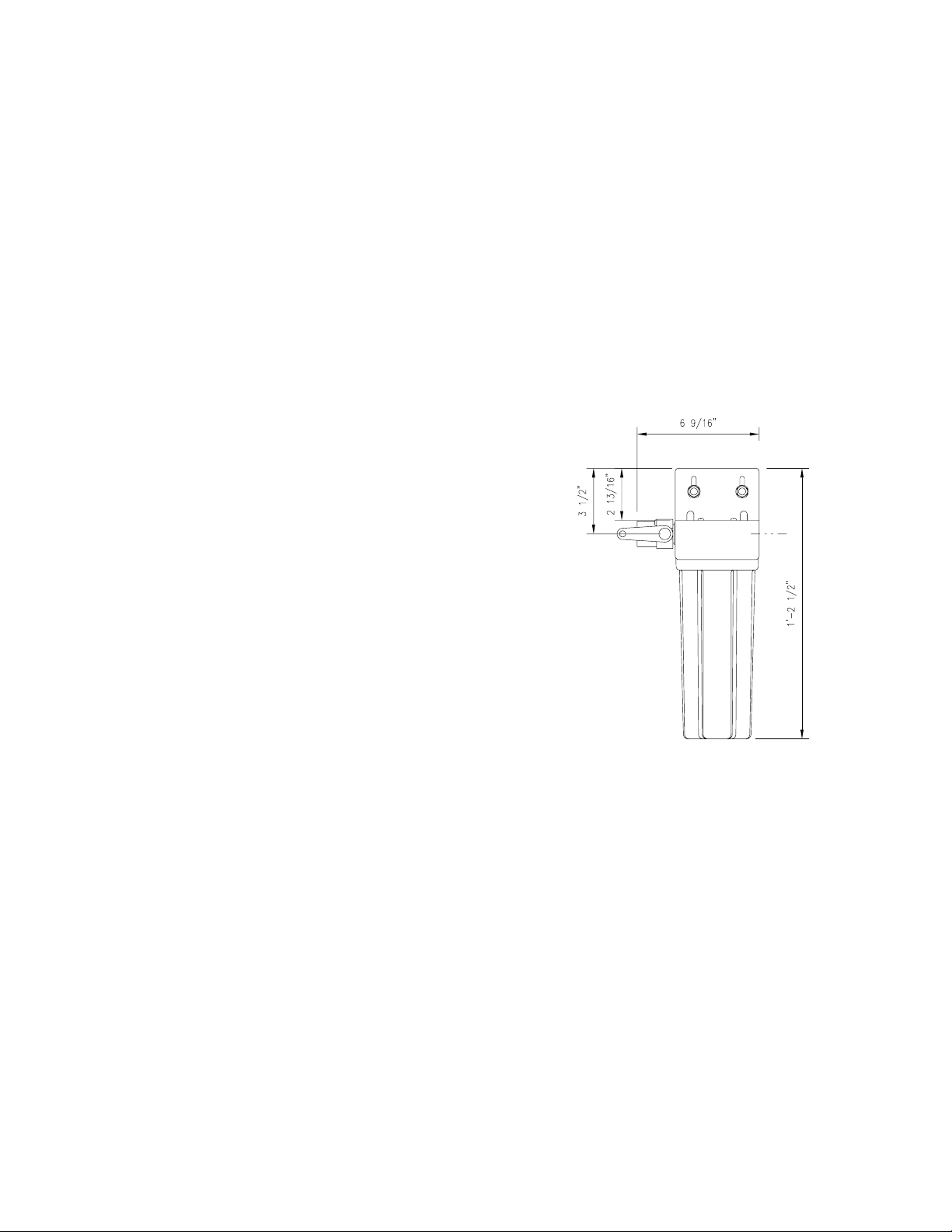
System Specifications & Dimensions
Maximum Pressure: 125 psi/8.6 bar
Maximum Temperature: 100°F/38°C, Min.: 35°F/2°C
Inlet/Outlet Connections: 1/2'' fnpt 1.5 & 3 gpm units
3/4'' fnpt 4 gpm units
Capacity: Change OneFlow Cartridge at least
once a year.
DO NOT DISCARD- GIVETHIS MANUAL TO THE OWNER AFTERINSTALLATION.
DO NOT DISCARD THIS MANUAL AFTERINSTALLATION. THIS MANUAL CONTAINS IMPORTANT OPERATION, MAINTENANCE AND PRECAUTIONARY INFORMATION.
PLEASE PRESENT THIS MANUAL TO USER/OPERATOR/OWNER AFTER INSTALLATION.
IT IS STRONGLYENCOURAGED THAT YOU READ THISMANUALBEFORE INSTALLING SYSTEM TO ENSURE THEBEST POSSIBLE INSTALLATION.
INSTALLATION MUST CONFORM TO ALL LOCALAND STATE PLUMBING CODES AND REGULATIONS.
CONNECT SYSTEM TO COLD WATER SUPPLY ONLY. WATER TEMP. CAN NOTEXCEED 100°F/38°C.
SYSTEM MUST BE INSTALLEDIN A VERTICAL AND UPRIGHT POSITION.
ONEFLOW SYSTEMS MUST NOT BE USEDIN CONJUNCTION WITH POLYPHOSPHATE OR ANYOTHER SCALE INHIBITOR.
DO NOT INSTALL FILTERS DOWNLINE FROMTHE ONEFLOW SYSTEM. ONEFLOW MUST BE THE LASTFILTER SYSTEM BEFORE THE EQUIPMENT.
DO NOT USE WITH WATERTHAT IS MICROBIOLOGICALLY UNSAFE OR OF UNKNOWN QUALITY WITHOUTADEQUATE DISINFECTION BEFORE OR AFTER THE SYSTEM.
FAILURE TO CHANGE CARTRIDGES PER RECOMMENDED INTERVALS WITH ONEFLOW REPLACEMENT CARTRIDGES MAYLEAD TO SYSTEM FAILURE AND
PROPERTY DAMAGE.
Installation Precautions
•DoNOT install system on line pressure above 125psi.
•DoNOT install thesystem backwards with the feed water line connected to the outlet.
•DoNOT use liquid pipe compoundsfor fitting connections. USE a maximumof twoto three wraps of teflon tape.
•DoNOT solder plumbing connectionsattached to filter housing or inlet valve. Inletvalve and filter housing will be damaged by high temperature.
•DoNOT allow system to freeze. Turn offwater supply to housing and drain housing if temperaturefalls below 32°F.
•DoNOT install system in direct sunlight or where system is exposed to harsh chemicals or may be subjected to being struck by moving equipment, carts, mops or
anyother item that may causedamage.
•IFwater hammer is evident, install water hammer arrestors before OneFlow unit.
•DoNOT overtightenfitting connections intoinlet valve ourhousing outlet.
•Always back-up valves and fittings with a wrench when installing a fitting to avoid turning thevalve.
•ALLOW a minimum of 3'' under the housing to allow for filter replacement.
Model: OF110-1
Capacity: 12 Months
Service Flow Rate: 1.5 gpm/5.7 lpm
Model: OF120-2
Capacity: 12 Months
Service Flow Rate: 3.0 gpm/11.3 lpm
Position the OneFlow unit in a suitable location downstream from existing filters. The direction of flow through the OneFlow unit is always left to right; keep this in
mind when determining installation location. Do NOT mount the OneFlow system near any source of heat. Also, do not mount the system above any device or area
that would be adversely affected by water.
Installation Procedure
1. Turn off all equipment to be fed by the OneFlow System, locate water supply
cut-off valve and turn off.
2. Determine if water line has an existing water treatment system. If so, examine
system for use of polyphosphate or other scale inhibitors. OneFlow will not be
effective if used in conjunction with other scale inhibitors. Remove the scale
inhibitors from the water line or discontinue installation.
3. Install a 1/2'' and 3/4'' full-flow ball valve on the water supply side that will feed
the water system.
4. Anchor the OneFlow System on a wall stud or suitable mounting material
spanning wall studs. System must be upright and vertical.
5. Run a suitable line from the 1/2'' full-flow ball valve at the tap water source to the
inlet ball valve on the left side of the OneFlow system. Use 2-3 wraps of teflon
tape and brace the inlet ball valve on the system with a wrench when connecting
the feed water line. NOTE: DO NOT OVERTIGHTEN CONNECTION FITTING INTO
BALL VALVE.
6. Select the appropriate size tubing for the equipment being fed and connect it to
the outlet of the OneFlow System. NOTE: DO NOT connect the tubing to the
equipment at this time. Prior to making connection to the equipment this line will
the outlet side of the OneFlow system could be provided in the line to
facilitate flushing when changing filters.
7. With System inlet valve closed, slowly open the 1/2'' full-flow ball valve at
the tap water source. Check for leaks.
8. If a drain valve was not installed on the outlet side of the system, hold the
tubing that will connect to equipment in a clean bucket or over sink or
drain. Open the system inlet feed valve and allow water to flush through
system for 10 minutes at the specified system flow rate to allow air and
any carbon fines to escape. NOTE: NO ACTIVATION IS REQUIRED FOR
THE ONEFLOW SYSTEM TO PERFORM PROPERLY. FLUSHING IS
RECOMMENDED TO ALLOW AIR TO ESCAPE THE SYSTEM AND
REMOVE ANY CARBON FINES PRIOR TO CONNECTING TO EQUIPMENT.
9. Make certain that the end of the tubing to be connected to the equipment
is clean and sanitized.
10. Connect tubing to equipment. Open all water supply valves and check
for leaks.
11. If no leaks turn on equipment and check for normal operation.
12. Register your warranty using the enclosed warranty card.
be used to facilitate flushing the system. As an option, a drain valve in a tee on
 Loading...