

Page 1
RP/IS-A-C200a/C300a
Double Check Valve
Assemblies
Double Check Detector
Assemblies
Sizes: 21⁄2" – 6" (65 – 150mm)
• Installation
• Service
• Repair Kits
• Maintenance
For other repair kits and service parts,
send for Ames Repair Parts Price List,
PL-A-RP-BPD.
For technical assistance, contact your
local Ames representative.
IMPORTANT: Inquire with governing
authorities for local installation requirements.
NOTE: For Australia and New Zealand, line
strainers should be installed between the
upstream shutoff valve and the inlet of the
backflow preventer.
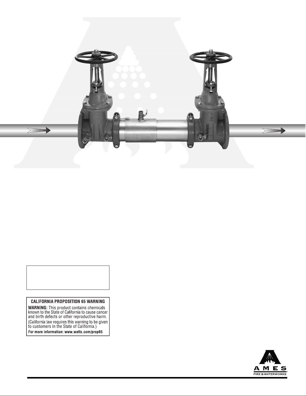
Colt
™
Series C200a, C300a
It's important that this device be tested
periodically in compliance with local codes,
but at least once per year or more as service
conditions warrant. If installed on a fire
sprinkler system, all mechanical checks,
such as alarm checks and backflow
preventers, should be flow tested and
inspected internally in accordance with NFPA
13 and NFPA 25.
C200a OSY
Installation Note: Due to shipping, storage,
and general handling, the Victaulic Coupling
for the shutoff valves may have loosened
and should be retightened during installation.
Limited Warranty: Ames Fire & Waterworks (the “Company”) warrants each product to be free from defects in material and
workmanship under normal usage for a period of one year from the date of original shipment. In the event of such defects within
the warranty period, the Company will, at its option, replace or recondition the product without charge.
THE WARRANTY SET FORTH HEREIN IS GIVEN EXPRESSLY AND IS THE ONLY WARRANTY GIVEN BY THE COMPANY WITH
RESPECT TO THE PRODUCT. THE COMPANY MAKES NO OTHER WARRANTIES, EXPRESS OR IMPLIED. THE COMPANY HEREBY
SPECIFICALLY DISCLAIMS ALL OTHER WARRANTIES, EXPRESS OR IMPLIED, INCLUDING BUT NOT LIMITED TO THE IMPLIED
WARRANTIES OF MERCHANTABILITY AND FITNESS FOR A PARTICULAR PURPOSE.
The remedy described in the first paragraph of this warranty shall constitute the sole and exclusive remedy for breach of warranty,
and the Company shall not be responsible for any incidental, special or consequential damages, including without limitation, lost
profits or the cost of repairing or replacing other property which is damaged if this product does not work properly, other costs
resulting from labor charges, delays, vandalism, negligence, fouling caused by foreign material, damage from adverse water
conditions, chemical, or any other circumstances over which the Company has no control. This warranty shall be invalidated by
any abuse, misuse, misapplication, improper installation or improper maintenance or alteration of the product.
Some States do not allow limitations on how long an implied warranty lasts, and some States do not allow the exclusion or limitation
of incidental or consequential damages. Therefore the above limitations may not apply to you. This Limited Warranty gives you
specific legal rights, and you may have other rights that vary from State to State. You should consult applicable state laws to
determine your rights. SO FAR AS IS CONSISTENT WITH APPLICABLE STATE LAW, ANY IMPLIED WARRANTIES THAT MAY NOT
BE DISCLAIMED, INCLUDING THE IMPLIED WARRANTIES OF MERCHANTABILITY AND FITNESS FOR A PARTICULAR PURPOSE,
ARE LIMITED IN DURATION TO ONE YEAR FROM THE DATE OF ORIGINAL SHIPMENT.
www.amesfirewater.com
A Division of Watts Water Technologies, Inc.
Page 2
2
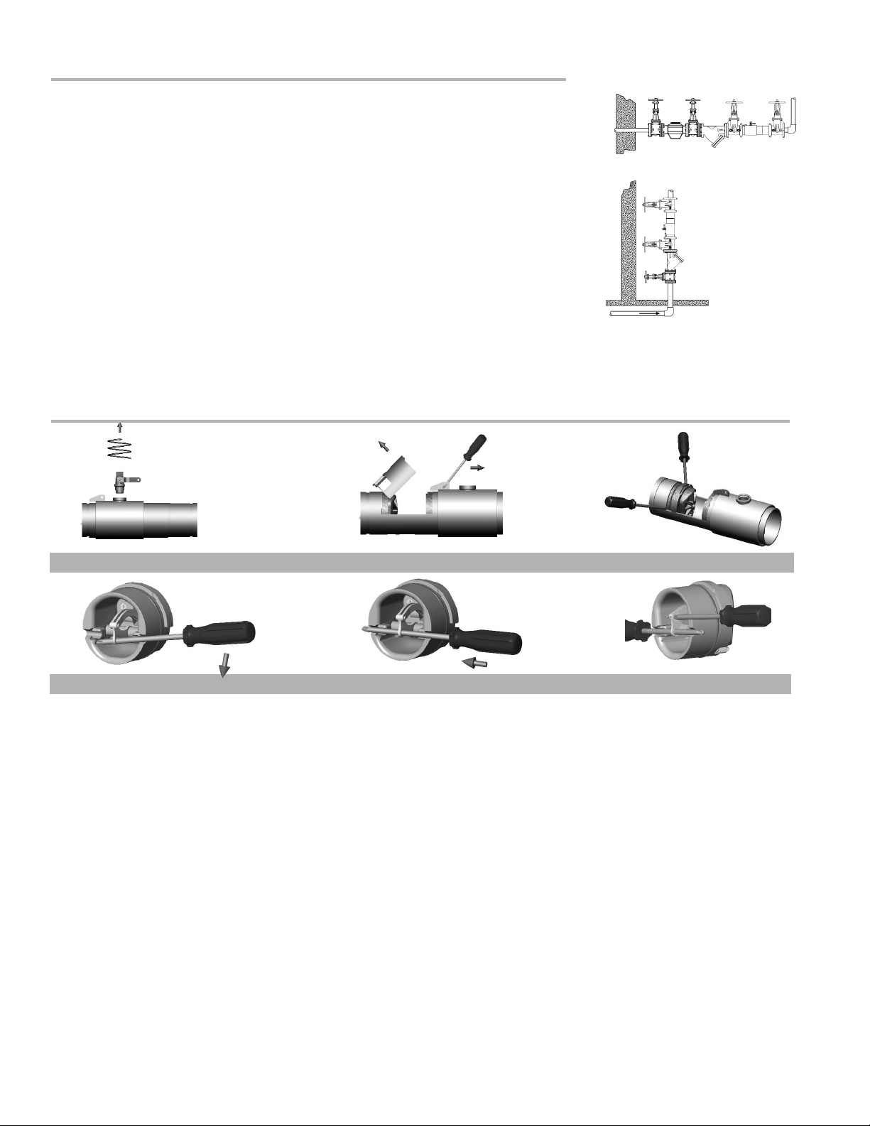
Prior to servicing any Ames valve, it is mandatory to shut
down the water system by closing both the inlet and outlet
shutoff valves. After shutoff valves are closed, open test cock
#2, #3 & #4 to relieve pressure within the backflow assembly.
1. After #3 test cock has been opened to relieve pressure,
remove #3 test cock from housing. (Figure A)
2. Insert a #3 screwdriver through the hole on the top of the
cover sleeve and using both hands rotate the cover sleeve
approximately
1
/4-turn clockwise and 1/4-turn counter-clockwise to break the sleeve O-ring seals. Using the screwdriver,
slowly slide the cover sleeve to the
downstream side of the housing. (Figure B)
3. Remove the stainless steel check retainer from the
housing. (Figure B)
4. Remove the #1 check module (Figure C) by inserting two
flat blade screwdrivers into the slots on either side of the
check module and gently pry the check module toward the
open zone.
5. Remove #2 check module with the same instructions
as in #4 above.
6. To clean or inspect either check module, insert a #3
screwdriver through the downstream side of the check
module as shown in Figure D & E. When the screwdriver
is in place, remove the “E”-clip (Figure F) and pin connecting the structural members and the check clapper will
open with no tension.
7. Thoroughly clean the seating area. The sealing disc may be
removed, if necessary, by removing the screws connecting
the keeper plate to the clapper. The sealing disc may be
reversed and reinstalled if the elastomer is cut or damaged.
8. Wash check module and O-ring and inspect for any damage. If damaged, reinstall new parts.
9. After thorough cleaning, lubricate O-ring w/FDA approved
lubricant, replace pin and “E”-clip in structural members,
remove screw driver and reinstall check modules and
assemble housing in reverse order of these instructions.
Basic Installation Instructions
Guidelines
Most field problems occur because dirt and debris present in the system at the time of
installation becomes trapped in the check valves. The system should be flushed before
the valve is installed. If the system is not flushed until after the valve is installed, remove
both check modules from the valve and open the inlet shutoff to allow water to flow for a
sufficient time to flush debris from the water line. If debris in the water system continues
to cause fouling, a strainer can be installed upstream of the backflow assembly.
The Series C200a and C300a may be installed in either horizontal or vertical position as
long as the backflow assembly is installed in accordance with the direction of the flow
arrow on the assembly and the local water authority approves the installation. The
assembly should be installed with adequate clearance around the valve to allow for
inspection, testing and servicing. 12" (300mm) should be the minimum clearance
between the lower portion of the assembly and the floor or grade.
Note: Assembly body should not be painted.
Horizontal Installation
Vertical
Installation
Figure D
Figure E
Figure F
Figure A
Figure B
Figure C
Maintenance Instructions
Instructions
Page 3

3
Ball Type Test Valves
A
C
B
Needle
Valve
High Hose
(Yellow)
Low Hose
(White or Red)
Vent Hose
(Blue)
Test Cock Test Cock Test Cock Test Cock
No. 1 No. 2 No.3 No.4
Test Check Valve No. 1
Step 1: Ensure shutoff #1 is open, shutoff #2 is closed.
Step 2: Connect high side hose to test cock #3, low side to test
cock #2 and open both test cock #2 and test cock #3.
Step 3: Open valve C, then open A to bleed air from the high
side. Close valve A, then open B to bleed low side.
Close valve B.
Step 4: Connect vent hose loosely to test cock# 1. Open valve
A to vent air from vent hose, Tighten vent hose at test
cock #1, open test cock #1.
Step 5: Close shutoff #1. Slowly loosen hose at test cock #2
until differential gauge rises to 2psi and retighten hose.
If the differential reading does not decrease, record
check valves as “tight”.
Test Check Valve No. 2
Step 1: Move the high side hose to test cock #4, low side to
test cock #3 and open both test cock #3 and test
cock #4. Remove vent hose from test cock #1, open
shutoff #1.
Step 2: Open valve C, then open valve A to bleed air from the
high side. Close valve A, then open valve B to bleed low
side. Close valve B.
Step 3: Connect vent hose loosely to test cock #1. Open valve
A to vent air from the vent hose. Tighten vent hose at
test cock #1, open test cock #1.
Step 4: Close shutoff #1, and then slowly loosen hose at test
cock #3 until differential gauge rises to 2psi and retighten hose. If the differential reading does not decrease,
record check as tight. Remove all hoses and restore
valve to original working condition.
Note: The assembly will fail both the first and second check valve
tests above, if shutoff #2 leaks excessively. To test for a leaky #2
shutoff, use the following procedure.
Test for Leaky No. 2 shutoff
Step 1: Connect the high side to test cock #1, low side to test
cock #4. Open test cock #1 and test cock #4. Close
shutoffs #1 and #2.
Step 2: Close valve C. Open valve A, then open valve B
1
/2 turn, loosen hose at test cock #4 to remove air.
Retighten hose.
Step 3: If the differential gauge rises above 0, there is excessive
leakage at shutoff #2 and it must be replaced to test the
assembly.
Testing — Double Check Valve Assemblies
Page 4

ITEM NO. PART DESCRIPTION 21/2" (65mm) 3" (80mm) 4" (100mm) 6" (150mm)
1 FIRST CHECK MODULE (a) (EPDM) 7018387 7018387 7018387 7018389
2 SECOND CHECK MODULE (a) (EPDM) 7018388 7018388 7018388 7018390
3 CHECK MODULE O-RING 7017861 7017861 7017861 7017910
4 ELASTOMER SHUTOFF DISC (EPDM) 7018329 7018329 7018329 7018330
5 GROOVED CLEVIS PIN KIT
(CONTAINS: “E” CLIP & CLEVIS PIN) 5 PER PACK 7018126 7018126 7018126 7018127
6 CLOSURE SLEEVE TEST-COCK WITH O-RING 7018152 7018152 7018152 7018153
7 CLOSURE SLEEVE 7017880 7017880 7017880 7017882
8 SLEEVE O-RING (2 REQ’D) 7017896 7017896 7017896 7017921
NS CHECK REPAIR KIT
(CONTAINS: O-RING, EPDM SHUTOFF
DISC & “E” CLIP) 7018391 7018391 7018391 7018392
NS TEST COCK, .50 FPT X FPT
WITH NIPPLE 7018394 7018394 7018394 N/A
NS TEST COCK, .75 FPT X FPT
WITH NIPPLE N/A N/A N/A 7018395
NS “E” CLIP 7017870 7017870 7017870 7017821
NS GROOVE COUPLER (SHUTOFF) 7017994 7017995 7018147 7018148
NS GROOVE COUPLER GASKET 7018882 7018883 7018884 7013248
NS O-RING, #3 TEST COCK 7017897 7017897 7017897 7017897
NS STAINLESS STEEL CHECK RETAINER 7018408 7018408 7018408 7018409
6. Closure Sleeve Test Cock with O-ring
7. Closure Sleeve
5. E-clip and Clevis Pin
4. Elastomer Shutoff Disc
2. Second Check Module
8. Sleeve O-ring
3. Check Module O-ring
1. First Check Module
Replacement Parts Listing
RP/IS-A-C200a/C300a 0904 EDP#7018380 ©Ames Fire & Waterworks 2009
www.amesfirewater.com
A Division of Watts Water Technologies, Inc.
USA: Backflow- 1427 N. Market Blvd • Suite #9 • Sacramento, CA 95834 • T: 916-928-0123 • F: 916-928-9333
Control Valves- 18550 Hansen Road • Houston, TX 77075 • T: 713-943-0688 • F: 713-944-9445
Canada: 5435 North Service Rd. • Burlington, ONT. L7L 5H7• T: 905-332-4090 • F: 905-332-7068
 Loading...