

Page 1
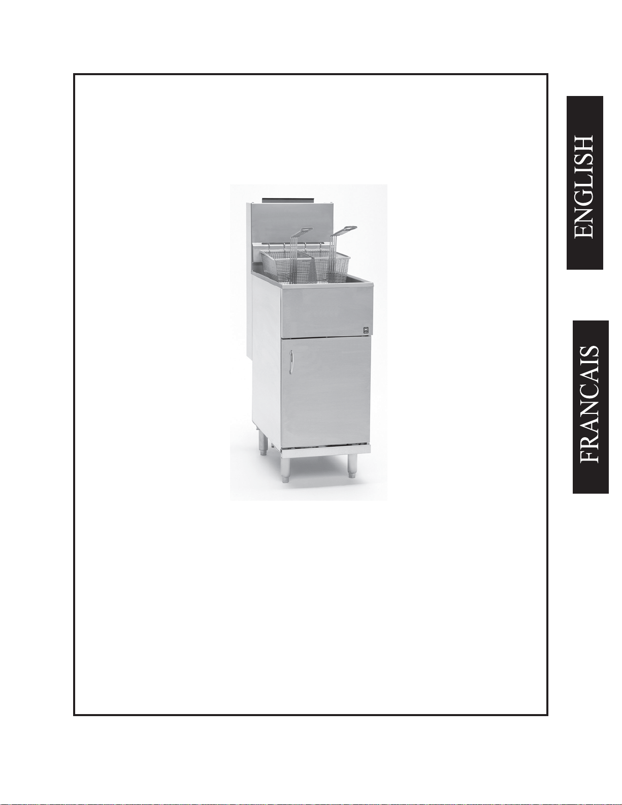
Installation, Operation, and Maintenance Manual
For Gas Fryers
Covering Models
40S & 40C
L20-251 R3
Page 2

TO THE PURCHASER
Post in a prominent location the instructions to be followed in the event
that an operator smells gas. Obtain this information from your local
gas supplier.
FOR YOUR PROTECTION
DO NOT store or use gasoline or other flammable vapors and liquids
in the vicinity of this or any other appliance.
Do not spray aerosols in the vicinity of this appliance when it is in
operation.
WARNING
Improper installation, operation, alteration, adjustments, service or
maintenance can cause property damage, injury or death. Read the
installation, operating and maintenance instructions thoroughly before
installing, operation, servicing this appliance.
WARNING
Installation, maintenance and repairs should be performed by a Pitco
Authorized Service and Parts (ASAP) company technician or other
qualified personnel. Installation, maintenance or repairs by an
unauthorized and unqualified personnel will void the warranty.
WARNING
Installation and all connections must be made according to local
codes in force. In the absence of local codes in North America, the
installation must conform with the National Fuel Gas Code, ANSI
Z223.1/NFPA 54 or the Natural Gas and Propane Installation Code
CSA B149.1 as applicable. In Australia, the appliance must installed
in compliance with AS/NZS 5601.
WARNING
During the warranty period if a customer elects to use a non-original
part or modifies an original part purchased from Pitco and/or its
Authorized Service and Parts (ASAP) companies, this warranty will be
void. In addition, Pitco and its affiliates will not be liable for any
claims, damages or expenses incurred by the customer which arises
directly or indirectly, in whole or in part, due to the installation of any
modified part and/or received from an unauthorized service center.
WARNING
This appliance, when installed, must be electrically grounded in
accordance with local codes, or in the absence of local codes, with the
National Electrical Code, ANSI/NFPA 70, or the Canadian Electrical
Code, CSA C22.2, as applicable
WARNING
Adequate means must be provided to LIMIT the movement or this
appliance without depending on the gas or electrical cord connection.
Single appliances equipped with legs must be stabilized by installing
anchor straps. All appliances equipped with casters must be stabilized
by installing restraining chains.
WARNING
DO NOT alter or remove structural material on the appliance to
accommodate placement under a ventilation hood.
WARNING
If the appliance is equipped with a power cord and it is damaged, it
must be replaced by a Pitco Authorized Service and Parts (ASAP)
company technician, or a similarly qualified person in order to avoid a
hazard.
WARNING
The power supply must be disconnected before servicing, maintaining
or cleaning this appliance.
WARNING
The appliance is NOT jet stream approved. DO NOT clean the
appliance with a water jet.
WARNING
DO NOT attempt to move this appliance or transfer hot liquids from
one container to another when the unit is at operating temperature or
filled with hot liquids. Serious personal injury could result if skin
comes in contact with the hot surfaces or liquids.
WARNING
DO NOT use an open flame to check for gas leaks!
WARNING
DO NOT sit or stand on this appliance. The appliance’s front panel,
tank, splash back, tank cover, work shelf, drain board is not a step.
Serious injury could result from slipping, falling or contact with hot
liquids.
NEVER use the appliance as a step for cleaning or accessing the
WARNING
ventilation hood. Serious injury could result from slips, trips or from
contacting hot liquids.
WARNING
The oil/shortening level should NOT fall below the minimum indicated
level line at any time. The use of old shortening can be dangerous as it
will have a reduced flash point and be more prone to surge boiling.
WARNING
The contents of the crumb catch and/or filter pan of any filter system
must be emptied into a fireproof container at the end of the frying
operation each day. Some food particles can spontaneously combust
into flames if left soaking in certain oil/shortening materials.
WARNING
Completely shut the appliance down when shortening/oil is being
drained from the appliance. This will prevent the appliance from
heating up during the draining and filling process. Serious injury can
occur.
WARNING
This appliance is intended for indoor use only.
WARNING
DO NOT operate appliance unless all panels and access covers are
attached correctly.
WARNING
It is recommended that this appliance be inspected by a qualified
service technician for proper performance and operation on a yearly
basis.
WARNING
There is an open flame inside this appliance. The unit may get hot
enough to set nearby materials on fire. Keep the area around the
appliance free from combustibles.
WARNING
DO NOT supply the appliance with a gas that is not indicated on the
data plate. If you need to convert the appliance to another type of fuel,
contact your dealer.
WARNING
If gas flow to appliance is interrupted, or pilots extinguish, wait 5
minutes before attempting to relight the pilot to allow any residual gas
in appliance to dissipate.
WARNING
Ensure that the appliance can get enough air to keep the flame burning
correctly. If the flame is starved for air, it can give off a dangerous
carbon monoxide gas. Carbon monoxide is a clear odorless gas that can
cause suffocation.
WARNING
Never add oil to the appliance when it is at operating temperature.
Splashing hot oil can cause severe injuries.
WARNING
Never add water to hot oil. Violent boiling can occur causing severe
injury.
WARNING
This appliance is intended for professional use only and should be
operated by fully trained and qualified personnel.
WARNING
To avoid splashing of hot liquid when installed, this fryer must be
restrained either by the manner of installation, or with adequate ties to
prevent tipping.
WARNING
An appliance equipped with casters and a flexible gas line must
be connected to the gas supply with a quick disconnect device. In North
America, gas appliances equipped with casters must be installed with
connectors that comply with the Standard for Connectors for Movable
Gas Appliances, ANSI Z21.69.CSA 6.16 Latest Edition. This
connection should include a quick disconnect device that complies with
the Standard for Quick Disconnect Devices for Use With Gas Fuel
ANSI Z221.41.CSA 6.9 Latest Edition. In Australia, an appliance
equipped with casters and a flexible gas line must be connected to the
gas supply with a quick disconnect device that complies with AS 4627.
The hose must comply with AS/NZS 1869 and be class B or D and have
a restraining cable. The restraining cable must not exceed 80% of the
length of the flexible gas line.
L20-251 R3
Page 3

Chapter 1: General Information and Installation
p
Congratulations on the purchase of your new 40S fryer. This unit will give you many years of reliable
service if you follow the simple operation and maintenance procedures in this manual. Contained in
this manual are the general installation, opera tion, and maintenance procedures for the 40S fryer.
1.1
WHICH FRYER DO I HAVE?
There are two models of this gas fryer available. Each fryer has its own model number. To find out
which model you have, look inside the door at the equipment identification plate. This plate has a lot
of useful information, but to identify which fryer you have, look at the model number block. The model
number identifies which fryer you have. A brief description of each model is provided inTable 1-1.
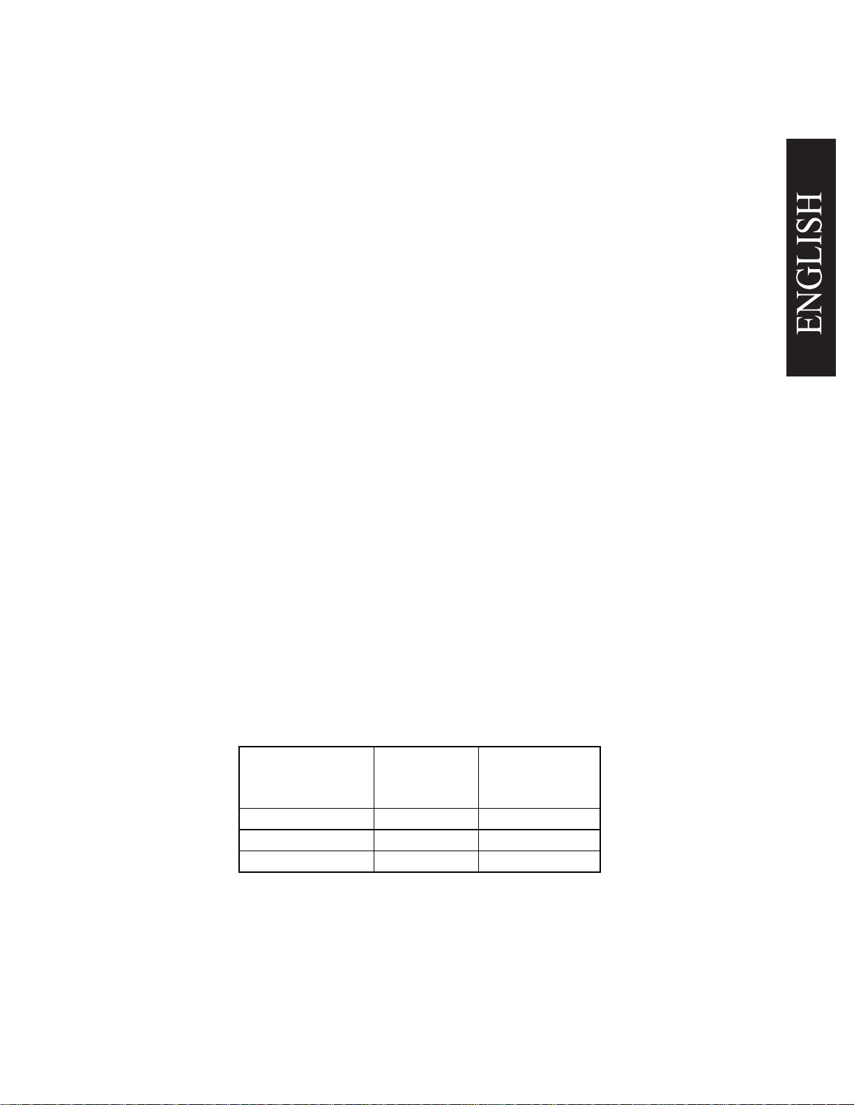
Table 1-1 Fryer Model Information
1.2
Your new fryer has been carefully packed into one crate. Every effort has been made to ensure that
your fryer is delivered to you in perfect condition. As you unpack your new fryer, inspect each of the
pieces for damage. If something is damaged, DO NOT sign the bill of lading. Contact the shipper
immediately, the shipper is only responsible for 15 days after delivery. Check the packing list enclosed
with your fryer to ensure that you have received all of the parts to the fryer. If you are missing any parts,
contact the dealer from whom the fryer was purchased. As you unpack the fryer and it's accessories
be careful to keep the weight of the fryer evenly distributed.
X X
1-1
Model
Number
40S & 40C This fryer can cook up to 72 lbs. (32.6 kg) of
CHECKING YOUR NEW FRYER
Description
otatoes per hour.
CAUTION
To prevent equipment damage, don't tilt the fryer onto
any two of it's casters or pull the unit by the flue vents.
Features
Frying Area: 14" x 14" (35.5 x 35.5 cm)
Oil Capacity: 40 lbs. (18.1 kg)
BTU Input: 105,000 (30.7kW)
L20-251 R3
Page 4
1.2.1
Check Your Order
The crate containing the fryer unit will also contain the following:
(1) Drain Clean Out Rod
1.3
ASSEMBLY AND LEVELING
When you receive your fryer, it is completely assembled with the possible exception of the legs (or
casters) and the heat shield. In some cases, if you have purchased a multi-fryer unit, you may need to
assemble the system.
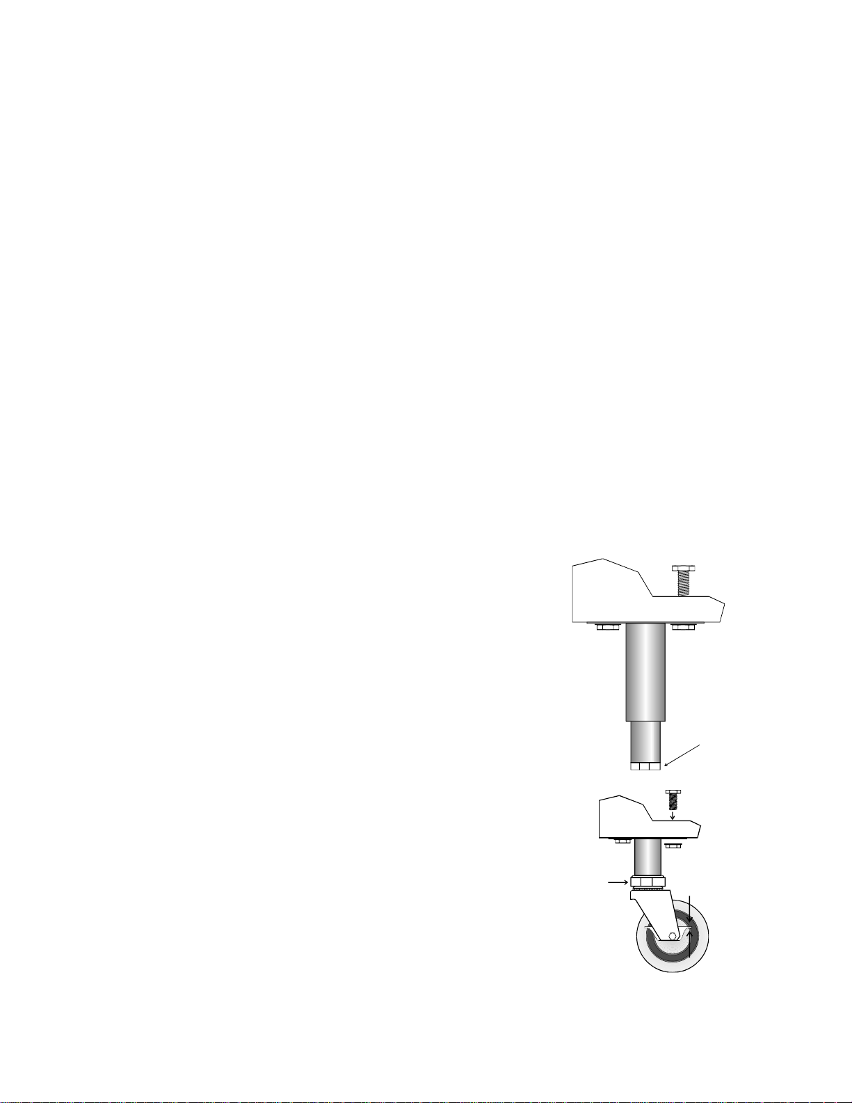
1.3.1
Leg/Caster Installation and Adjustment
Installing the legs and leveling the fryer is done with a 7/16" wrench, socket, and a large pair of water
pump pliers. The legs/casters must be installed to provide the necessary height to meet sanitation
requirements and assure adequate air supply to the burner. Attach the legs by performing the following
procedure.
a. Lay the fryer on its side being careful not to damage the flue
by pulling on it. Protect the outside of the fryer with
cardboard or a drop cloth when laying it down.
b
. Attach each leg/caster with the hex head cap screws sup-
plied with the fryer. Each leg/caster requires four 1/4-20 x
5/8" cap screws.
c
. Mount the screws from the inside of the fryer with the nut
on the outside. The nuts have lock washers attached to
them, therefore it is not necessary to use lock washers.
d
. When all four legs/casters are mounted, stand the unit up
being careful not to put too much weight on any one leg/
caster.
Adjust the height and level the fryer by adjusting the
leveling devices on the leg/caster with the water pump
pliers.
e. On units with casters, move the fryer to the desired location
Adjust
Here
and lock the wheels using the locking devices on the sides
of the casters.
1-2
Adjust Here
Lock
Un Lock
L20-251 R3
Page 5
1.3.2
Assembling Multi Fryer Systems
If you purchased a multi-fryer unit, it could be shipped in more than one piece. To assemble the unit
follow the instructions below.
a
. Unpack the units and move them close together. Remove the front panels and both heat
shields from the fryers.
b. There are five joining strips to be attached to the units to make them into one system. These
strips are attached in the rear, front, upper front, and the forward and rear caster mount. Use
the screws supplied with your system to attach the strips. Secure them tightly to each unit.
c
. Replace the heat shield and front panels to complete the system assembly.
1.4
INSTALLATION
Although it is possible for you to install and set up your new fryer, it is STRONGLY recommended
that you have it done by qualified professionals. The professionals that install your new fryer will know
the local building codes and ensure that your installation is safe.
WARNING
The fryer must be properly restrained to prevent movement or tipping.
This
restraint must prevent the fryer from movements that would splash hot liquids
on personnel. This restraint may be any means (alcove installation, adequate
ties, or battery installation).
1.4.1 Installation Clearances
The fryer needs clearance around it for proper operation. Adequate clearances allow for servicing and
proper burner operation. The clearances shown below are for cooker installation in combustible and
non-combustible construction.
Combustible
Construction
Non‐
Combustible
Construction
Back 6"(15.2cm) 0"
Sides 6"(15.2cm) 0"
Floor‐Combustible 6"(15.2cm) 6"(15.2cm)
1.4.2
Gas Connection
Your fryer will give you peak performance when the gas supply line is of sufficient size to provide the
correct gas flow. The gas line must be installed to meet the local building codes or National Fuel Gas
Code (NFPA 54-Latest Edition) and ANSI Z223.1-Latest Edition Latest Edition. In Canada, install
the fryer in accordance with CAN/CGA-B149.1 or .2 and local codes.
1-3
L20-251 R3
Page 6

Gas line sizing requirements
Fuel Gas Code, Appendix C,
can be determined by your local gas company by referring to National
Table C-4 (natural gas) and Table C-16 (propane). The gas line
needs to be large enough to supply the necessary amount of fuel to all appliances without losing
pressure to any appliance. Other factors that are used to determine the piping requirements are
BTU requirements of the appliances being connected and the length of pipe between the meter
(main shut off) and the appliances.
WARNING
NEVER supply the fryer with a gas that is not indicated on the data plate. Using
the incorrect gas type will cause improper operation. If you need to convert the
fryer to another type of fuel, contact your dealer.
1.4.2.1
Fuel Types - Each fryer is equipped to work with one type of fuel. The type of fuel with
which the appliance is intended to operate is stamped on the data plate attached to the inside of the door.
WARNING
DO NOT use an open flame to check for gas leaks!
1.4.2.2
Gas Line Connection - Connect the fryer to the gas supply line with a connector that
complies with the Standard for Connectors for Movable Gas Appliances (ANSI Z21.69-Latest
Edition)
. If you are installing a fryer with casters use a quick disconnect refer to the Quick Disconnect
installation instruction, 1.4.2.3. Connect the gas line to the fryer using a pipe joint sealant that is resistant
to liquefied petroleum. If the fryer was disconnected during the fuel line testing, use a solution of soap
and water to leak test the new connection.
NOTICE
NEVER use an adaptor to make a smaller gas supply line fit the cooker
connection.
This may not allow proper gas flow for optimum burner operation,
resulting in poor cooker performance.
1.4.2.3
Quick Disconnect Gas Connection - Gas fryers equipped with casters must be installed
with connectors that comply with the Standard for Connectors for Movable Gas Appliances, ANSI
Z21.69-Latest Edition, and Addenda Z21.69A-Latest Edition. This connection should include a
quick disconnect device that complies with the Standard for Quick Disconnect Devices for Use
With Gas Fuel , ANSI Z21.41-Latest Edition. When installing a quick disconnect you must also
install a means for limiting the movement of the fryer. This device will prevent the gas line or the
quick disconnect from being strained. The restraining device should be attached to the cooker on
the back panel as shown in the illustration. The quick disconnect, hose, and restraining device can
be obtained from your dealer.
1-4
L20-251 R3
Page 7

1.4.2.4
Fuel Supply Line Leak and Pressure Testing - The fuel supply system must be tested before
fryer is used.
If the fuel line is going to be tested at a pressure greater than (>)1/2 PSIG (3.45 kPa),
the fryer is disconnected from the fuel line. If the fuel line is to be tested at a pressure
less than (<) 1/2 PSIG (3.45 kPa), the fryer can be connected but the unit's gas valve must
make sure that
equal to or
be shut
Test all gas line connections for leaks with a solution of soap and water when pressure is applie d .
1.4.3
Ventilation and Fire Safety Systems
Your new fryer must have proper ventilation to function safely and properly. Exhaust gas temperatures
can reach as high as 1200°F (648°C). Therefore, it is very important to install a fire safety
system. Your ventilation system should be designed to allow for easy cleaning. Frequent cleaning
of the ventilation system and the fryer will reduce the chances of fire. Table 1-2 provides a list of
reference documents that provide guidance on ventilation and fire safety systems. This table is not
necessarily complete.
8501 East Pleasant Valley
Additional information can be obtained from the American Gas Association,
Road, Cleveland, OH 44131.
Excessive ventilation causes drafts, which will interfere with the proper operation of the pilot and
the burner. Leave at least 18 inches (45cm) of open space between the fryer's flue vent opening
and the intake of the exhaust hood.
CAUTION
Ensure that your ventilation system does not cause a down draft at the fryer's
flue opening. Down drafts will not allow the fryer to exhaust properly and will
cause overheating which may cause permanent damage. Damage caused by
down drafts will not be covered under equipment warranty. NEVER allow
anything to obstruct the flow of combustibles or ventilation exiting from the
fryer flue. DO NOT put anything on top of the flue area.
NOTICE
NEVER connect the blower directly to the flue openings. The direct flow of
air will cause poor temperature recovery, poor ignition, inefficient operation of
the fryer, and could extinguish the pilot.
1.5
INITIAL ADJUSTMENTS
After your fryer has been installed as described in section 1.4, it needs to be adjusted to ensure that it
will perform as designed. These adjustments must be performed by a qualified person. To perform
these adjustment the following tools will be needed:
• Manometer (low pressure gauge) • Digital Thermometer (Temperature probe)
• DC Millivolt Meter
1-5
the
.
L20-251 R3
Page 8

1.5.1
Visual Checks
After the fryer is in its permanent location, lock the casters and check for levelness. Any additional
leveling that is necessary can be performed as described in section 1.3.
1.5.2
Burner Ignition Systems
CAUTION
Before going any further, fill the fryer with WATER. Water is used for the
installation adjustments because the temperature will never exceed 212°F
(100°C) thereby allowing plenty of adjustment time. Never let the water level
go below the MIN LEVEL mark on the rear of the tank.
WARNING
There is an open flame inside the fryer. The unit may get hot enough to set near
by materials on fire. Keep the area around the fryer free from combustibles.
To light the pilot light, refer to these instructions.
Table 1-2. Ventilation and Fire Safety References
Topic
Grease Extractor
Ventilation Hood
Type of Fire Extinguishers and
Detection Equipment
CO
2
Dry Chemical
Water
Foam
Sprinklers
Smoke Detectors
Fire Detection Thermostats
Underwriters Laboratory
Document
ANSI/UL 710-Latest Edition
ANSI/UL 705-Latest Edition
ANSI/UL 154-Latest Edition
ANSI/UL 299-Latest Edition
ANSI/UL 626-Latest Edition
ANSI/UL 199-Latest Edition
ANSI/UL 268-Latest Edition
ANSI/UL 521-Latest Edition
1-6
National Fuel Gas Code
Document
ANSI/NFPA 96-Latest Edition
ANSI/NFPA 96-Latest Edition
ANSI/NFPA 12-Latest Edition
ANSI/NFPA 17-Latest Edition
ANSI/NFPA 13-Latest Edition
ANSI/NFPA 11-Latest Edition
ANSI/NFPA 13-Latest Edition
ANSI/FPA 72B-Latest Edition
ANSI/FPA 72B-Latest Edition
L20-251 R3
Page 9

WARNING
Wait 5 minutes before attempting to relight the pilot to allow for any gas in the
fryer to dissipate.
a
. Open the gas supply valves to the fryer.
b
. Open the fryer's door to gain access to the controls. Turn the thermostat control knob
counterclockwise to the OFF position.
c
. Turn the Unitrol valve knob to the PILOT position and push in on the knob. Hold the knob
in for approximately one minute to purge the air out of the line. Hold a
flame to the pilot light until the pilot ignites. This may take a little while
the first time you light the fryer because of air in the lines. Once lit, hold
the knob in for approximately 60 seconds and then release.
d
. If the pilot goes out wait 5 minutes and repeat step c. If after three tries
the pilot will not remain lit, refer to the operator troubleshooting section
of this manual.
e
. Turn the Unitrol valve knob counterclockwise to the ON position.
f. Set the thermostat control knob to the desired temperature setting.
g
. The main burner will light and be controlled by the thermostat.
h
. To completely shut down the fryer, turn the Unitrol valve knob to pilot,
push in and continue turning to OFF.
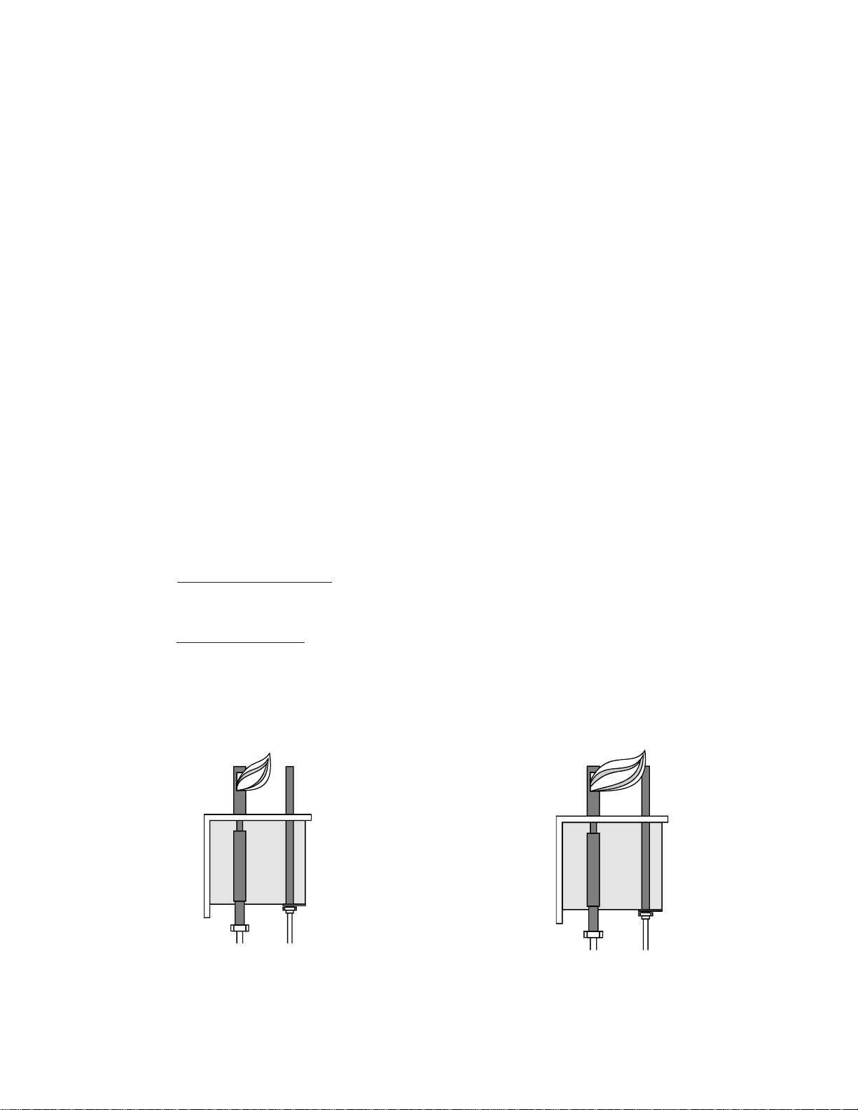
1.5.2.1
Pilot Flame Adjustment - The pilot flame should be adjusted to produce the proper millivolt
output from the pilot sensing device. Millivolt output for the thermopile should be between 300 and
500 millivolts. This procedure is only necessary on the manual pilot ignition system. Figure 1-1 shows
the pilot assembly with examples of the incorrect and correct pilot s ize. Example A illustrates a pilot
flame size that is too small to produce sufficient millivolt output. Example B is the correct size for proper
millivolt output.
a
. This test requires a DC millivolt meter set to a scale of 0-1000mv.
b
. Locate the thermopile wires coming from th e thermostat/High Limit box going to the gas
shut off valve. The wire insulation size decreases near the gas valve connections.
c
. Connect the negative (-) test probe to pilot bracket.
1-7
L20-251 R3
Page 10
d
. Connect the positive (+) test probe to to one of the High Limit terminal connections
e
. Remove the pilot flame adjustment cover.
f. Turning the flame adjusting screw clockwise lowers the flame and the millivolt output.
Turning the screw counterclockwise increases flame size and millivolt output.
g
. Rotate the screw in the direction to achieve a reading of 400 ±50 mv for thermopiles.
NOTICE
Allow 3 to 5 minutes between flame adjustments to allow the reading to settle.
h
. Replace the pilot flame adjusting screw cover.
1.5.3
Main Burner System
For the burners to work, the gas supply valve must be open. The main burner receives gas from the
main gas supply through the thermostatically controlled valve. When the thermostat is turned up the
gas control valve opens. The pilot ignites the burners. The burner flame should be adjusted at the air
collar (at the bottom of the burner) so the the flame are a soft blue color without lifting of f the face of
the burner.
1.5.3.1
Gas Line Requirements - A properly installed gas supply system will deliver 7.0 -9 .0 " w.c.
natural gas (11.0-13.0" w.c. LP) to all appliances connected to the line, operating at full demand.
1.5.3.2
Burner Adjustment - The burners must be adjusted to deliver optimum flame. Adjust the
burner flame using the following procedure.
a. Ensure that the Unitrol valve knob is in the OFF position. Remove the manifold pressure
A
B
Figure 1-1 Pilot Assembly, Flame Adjustment
1-8
L20-251 R3
Page 11
tap plug and connect an accurate pressure gauge (range of 0-16" w.c. in 0.1" increments)
or manometer.
b
. Light the pilot burner (see 1.5.2) for the unit being tested and adjust the thermostat to light
the main burners.
c
. The installed pressure gauge reading should be the same, ±0.1", as that marked on the data
plate inside the door. If the pressure is correct go to step e, if not, adjust the pressure.
Incoming pressure, Natural or Propane, can not exceed ½ psi. Proper burner pressure
for this model is NAT 4.0” w.c. (10.2 mbar), LP 10.0: w.c (25.4 mbar).
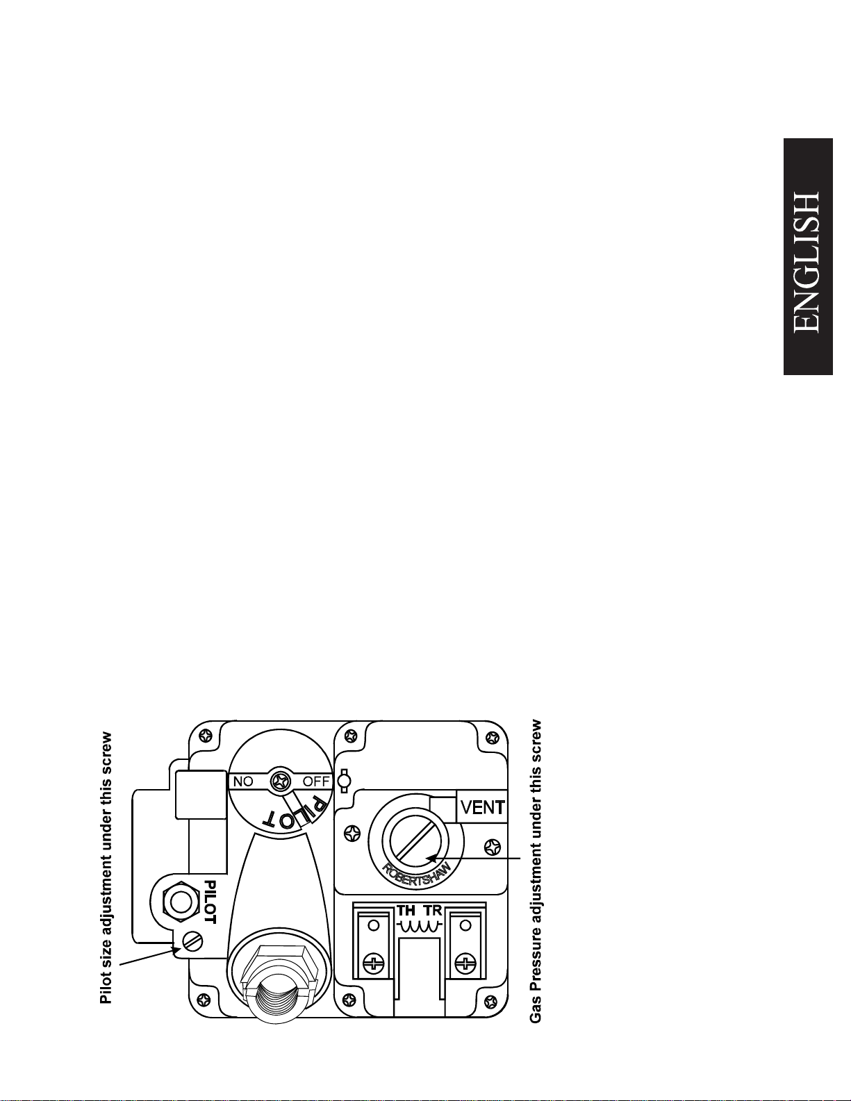
d. To adjust the pressure, remove the regulator adjustment screw cover (see Figure 1-3). Use
a flat tip screwdriver to adjust the screw until the proper pressure is reache d. Turning the
screw clockwise will increase the pressure, counterclockwise will decrease the pr essure.
e
. When the pressure is correct, install the regulator adjustment screw cover.
To remove the pressure gauge, turn gas control valve to OFF. Remove the gauge and install
f.
the pressure tap plug.
g
. Now that the pressure is set for proper operation, set the main burner flame. Unlock the air
collars by loosening the set screw for the collars. See Figure 5. Turn the Unitrol valve knob
to ON and turn thermostat to light the main burners.
h
. Adjust the shape and size by raising or lowering the air collars to achieve a soft blue flame
with well defined inner cones.
i. When the flames have been properly adjusted, lock the collars in place with the set screw
provided.
1.5.4 Initial Cleaning
When the fryer is shipped, many of its parts are covered with a thin coat of oil for protection. Before
the fryer is ready for cooking it must be cleaned. This will remove the oil coating and any foreign matter
that may have accumulated during storage and shipment. Perform the cleaning as described below.
a
. Fill the tank with water and add one packet of m ild detergent.
Figure 1-2 Gas Valve
Showing Location of the
Pressure Regulator and
Pilot Adjusters
1-9
L20-251 R3
Page 12

b
. Turn the fryer on and set the thermostat to 200°F (93°C). Allow the fryer to heat for 15 minutes.
NOTICE
Do not leave the fryer unattended during cleaning. Never let the water level go
below the "Min Level" mark on the back of the tank.
c
. Using the fryer cleaning brush, scrub the inside of the fryer to remove protective coating.
d. When cleaning is complete, turn off the fryer main burners and turn the Unitrol valve knob
to the PILOT position. Drain the water into a container suitable for hot water and dispose
of it.
e
. When the tank has cooled, rinse it thoroughly with cool water. Continue to rinse the tank
until the cleaner has been rinsed, thoroughly from the tank.
f. Using a clean dry cloth, wipe out all of the water. Be very thorough removing the water,
because any residual water will cause hot oil to splatter out of the fryer.
CAUTION
Mild steel tanks must be wiped down/coated with oil to keep the tank from
rusting.
g
. Now that the tank is clean, you are ready to fill and operate the fryer. Refer to 2.1 for
instructions on adding shortening to the fryer.
1.5.5
Thermostat Calibration Check
NOTICE
Thermostat calibration requires that the temperature of the fryer be raised above
boiling.
oil
Therefore, you will need to drain the water from the fryer and fill it with
. Before removing the water, perform the initial cleaning of the fryer.
Cleaning the fryer now will prevent you from having to drain the oil and refill
with water later.
Filling the fryer with oil is described in 2.1. To perform the calibration check detailed below you will
need a digital thermometer.
a. Place the tip of the thermometer in the shortening approximately 1"(2.5cm) above the
temperature
sensors.
1-10
L20-251 R3
Page 13

b. Set the thermostat at 325°F (162°C) and wait for the temperature reading on the thermometer to rise.
As the temperature rises toward 325°
c
. If the shortening temperature reaches 350°F
turn the thermostat down. Keep lowering the thermostat setting until the burners go
out.
If the burners do not turn off at the lowest thermostat setting, the thermostat
could be defective. Contact your representative immediately.
d. Let the fryer cycle 4 to 6 times before checking the temperature. Compare the thermometer
temperature against the thermostat setting. If the values are more than 5°F (2.5
calibrate the thermostat using the appropriate calibration procedure in this manual.
1.5.6 Thermostat Calibration
a. Place the tip of the thermometer in the shortening approximately 1" (2.5cm) above the
temperature
sensors.
b. Set the Thermostat to 325°F (162°C) and wait for the temperature reading on the thermometer to rise.
c
. Let the fryer cycle 4 to 6 times to ensure that the temperature has stabilized. Compare the
thermometer temperature against the thermostat setting. If the values are more than 5°F
(2.5
°C)
apart, calibrate the thermostat using the appropriate calibration procedure.
(162°C)
CAUTION
F watch the thermometer closely.
(176°C)
and the burners DO NOT turn off,
°C)
apart,
1-11
L20-251 R3
Page 14

1-12
L20-251 R3
Page 15

Chapter 2: Operating Instructions
This chapter describes how to operate your fryer to obtain the best performance. Included in this
chapter are filling, operating, and cleaning instructions for gas fryers.
2.1
FILLING THE FRYER
Both liquid and solid shortening can be used in the fryer, but liquid is preferred. To melt solid
shortening, carefully follow the instruction in section 2.2.2.
2.1.1
Filling the Fryer With Liquid Shortening
a
. Make sure the drain valve is completely closed.
b
. Fill the fryer with oil to the "Oil Level" line marked
on the back of the tank.
2.1.2
Filling the Fryer With Solid Shortening
Never melt blocks of solid shortening on top of the burner
tubes
a
. Make sure the drain valve is completely closed.
b
. Remove the screen covering the tubes.
c
. Cut the shortening into cubes no larger than
1".(2.5cm)
between, and on top of the burner tubes. DO NOT
leave any large air gaps. Use care when packing
the solid shortening in the tank. DO NOT bend or
break the temperature sensor probes. If these are
damaged the fryer will not function properly.
d
. Once the fryer is packed with shortening, the short-
ening must be melted. To melt the shortening, refer
to Fryer Start-Up, section 2.2.1, and Melting Solid
Shortening, section 2.2.2.
ALWAYS pack the shortening below,
. This will cause a fire and will void your warranty.
WARNING
2-1
L20-251 R3
Page 16

2.2
OPERATING INSTRUCTIONS
To ensure the food always comes out the very best, follow the preparation instructions for the food
you are cooking. Using the best shortening makes the best fried foods. The best shortening will last
longer than lower grade shortening and save you money. When not in use the shortening should be
cooled and covered to prevent contamination.
CAUTION
The fryer has been installed using restraining devices to prevent accidental
tipping or movement. Do not attempt to move the fryer when it has hot liquid
in it
. Splashing hot liquids can cause severe burns.
WARNING
Water and shortening DO NOT mix. Keep liquids away from hot shortening.
Dropping liquid frozen food into the hot shortening will cause violent boiling.
2.2.1
Fryer Start-Up
DO NOT START FRYER WITHOUT FILLING WITH OIL!
a
. Light the pilot light as described in section 1.5.2.
b
. Turn the temperature control knob (thermostat) to the desired temperature setting. This
knob is located behind the front doors or on the front control panel.
c
. The main burners will light.
2.2.2
Melting Solid Shortening
NOTICE
The melting procedure below requires cycling of the fryer. Watch carefully
for smoke. If smoke is noticed, the shortening is scorching. To prevent this,
decrease the time you leave the burners on.
a
. Place the Unitrol valve in ON position.
b
. Set thermostat to 150°F (65°C).
c
. Allow main burners to fire for approximately four (4) seconds.
d
. Turn thermostat down until main burners go out.
2-2
L20-251 R3
Page 17

e
. Wait 30 seconds.
f
. Repeat steps c. through e. until the shortening is melted.
g. Set thermostat to normal operating temperature. The burners will remain on constantly
until the shortening temperature reaches the thermostat setting.
h
. Once at temperature, the fryer is now operating normally and ready to use.
2.2.3
Fryer Shut-Down
There are two shutdown modes of fryer operation, STANDBY and COMPLETE. The standby mode
removes the ability for the fryer's main burners to cycle. Complete shutdown turns off the gas supply
to the fryer. Shut down the fryer by:
STANDBY
Turn the thermostat to OFF. Turn the gas valve clockwise to the
PILOT position. The cooker is now in Standby and can remain this
way for only brief periods of time. NEVER leave the cooker in
standby overnight.
COMPLETE To completely shut down the cooker, push and turn the gas valve
counterclockwise to the OFF position. The fryer is now completely
shut down and can be cleaned and filtered.
2.3
DAILY CLEANING
Your fryer should be cleaned every day to maintain peak performance and appearance. Perform the
procedures below every day.
a
. Wipe up any shortening that spills onto the exterior of the fryer. This should be done with
a clean soft cloth while the oil is still warm.
b
. Use warm water with a mild detergent to clean surfaces. Be careful not to get water in
the shortening and to remove any detergent from the fry tank.
c
. Use a non-abrasive scouring powder or pad to clean stains if necessary.
d
. Perform the weekly boil out cleaning of your fryer described in section 3.2.
2-3
L20-251 R3
Page 18

Chapter 3: Owner Maintenance and Adjustments
This chapter provides you with the information and procedures necessary to perform basic fryer
maintenance and adjustments. If, after performing maintenance on your fryer, it does not perform
properly, contact your authorized service center.
3.1
WEEKLY FRYER CLEANING (BOIL OUT)
The fryer should be thoroughly cleaned once a week. This cleaning should include a complete draining
of the fryer and a boil out.
a. You will need a container large enough to hold 1 1/2 times the oil in one tank. This container
should also be able to withstand boiling water temperatures.
CAUTION
Completely shut down the fryer when the oil is to be replaced by water, and
when the heating portion of the cleaning is complete. This will prevent the
heating system from coming on during the oil draining and water filling
procedure.
b
. Drain the oil from the fryer and discard or save for reuse. Remove tube rack/mesh tube
screens and remove any large debris from the bottom of the fry tank. Once clean, return
tube rack/mesh screens to the fry tank. Close the drain valve and fill the fry tank with water
and noncaustic detergent.
c
. Restart your fryer as described in 2.3 and set the thermostat to 200°F (93°C) and bring
the water to a slow boil. DO NOT allow water to boil because excessive foaming will
occur. Once the water is at a slow boil turn off the fryer.
d
. Allow the fryer to soak for 20 minutes to soften shortening deposits and carbon. Use the
fryer brush to remove any residue from tank, heating tubes, and side walls. Perform the
daily cleaning procedure described in section 2.6.
e
. Wipe the tank dry with clean cloth wipes. Close the drain valve and remove the large
container.
f. Refer to section 2.1 to refill the fryer.
3.2
FLUE INSPECTION
It is recommended that once every six months, with the cooker cooled down, you examine the flue area.
Check for corrosion or blockage of the flue. Ensure that the cooker is shutdown and do not turn it on
during the examination. Examination of the flue area during cooking may cause bodily injury.
3-1
L20-251 R3
Page 19

3.3 TROUBLESHOOTING
This section is provided to aid you in the event of fryer or filter troubles. If these troubleshooting
procedures do not correct your problem contact a qualified technician or the factory. The troubleshooting procedures are in a flowchart format.
3-2
L20-251 R3
Page 20

3-3
L20-251 R3
Page 21

ENGLISH
3-4
Page 22

Manuel d’installation, d’utilisation et d’entretien
pour friteuses à gaz
Modèles
40S, 40C
L20-251 R3
Page 23

AVIS À L’ACHETEUR
Afficher en évidence les instructions à suivre si un utilisateur sent une
odeur de gaz. Cette information est disponible auprès de votre fournisseur
local de gaz.
MESURE DE SÉCURITÉ
NE PAS entreposer ni utiliser d’essence ni autres vapeurs ou liquides inflammables
àproximité de cet appareil ou de tout autre app areil.
AVERTISSEMENT
L’installation, le réglage, la modification, la réparation ou l´entretien
incorrects de cet appareil peuvent causer des dommages matériels, des
blessures ou la mort. Lire attentivement les instructions d´installation, de
fonctionnement et d´entretien avant de procéder à son installation ou
entretien.
AVERTISSEMENT
L’installation, l’entretien et les réparations doivent être effectués de
préférence par un technicien Pitco agréé entretien et pièces détachées ou
un autre technicien qualifié. Toute installation, entretien ou réparation
effectuée par une personne non autorisée et non qualifiée annule la
garantie.
AVERTISSEMENT
L’installation et tous les raccordements doivent obligatoirement être
effectués conformément aux codes locaux en vigueur.
En Amérique du Nord, en l’absence de codes locaux, l’installation doit se
conformer au code national relatif au gaz combustible, ANSI Z223.1/NFPA
54, ou au code d’installation relatif au gaz naturel et au propane, CSAB149.1 : si applicables. En Australie, et appareil doit être installé
conformément à la norme AS/NZS 5601.
AVERTISSEMENT
Si, pendant la période de garantie, un client utilise une pièce qui n’est pas
d’origine ou modifie une pièce d'origine achetée auprès de Pitco et (ou) de
ses prestataires d’entretien et de pièces détachées autorisées, la présente
garantie sera nulle et non avenue. De plus, ni Pitco ni ses filiales ne seront
responsables d’aucune plainte, dommages ou frais encourus par un client
et qui découleraient, directement ou indirectement, en tout ou en partie, de
l'installation d’une pièce modifiée et (ou) obtenue auprès d'un centre de
réparation non agréé.
AVERTISSEMENT
Cet appareil doit obligatoirement être mis à la terre électriquement conformément
aux codes locaux ou, en l’absence de code local, conformément au National Electrical
Code, ANSI/NFPA 70 ou au Code canadien de l'électricité CSA C22.2, selon le cas, et
le tuyau doit être conforme à la norme AS/NZS 1869 et être de classe B ou D.
AVERTISSEMENT
Cet appareil doit obligatoirement disposer de moyens adéquats pour
LIMITER ses déplacements indépendamment des raccordements au gaz ou
à l’électricité. Les appareils simples équipés de pieds doivent
obligatoirement être stabilisés à l’aide de sangles d’ancrage. Tous les
appareils à roulettes doivent obligatoirement être stabilisés par des chaînes
de retenue.
AVERTISSEMENT
Tout appareil à roulettes équipé d’un flexible de gaz doit obligatoirement
être raccordé à la source de gaz par l’intermédiaire d’un raccord à
débranchement rapide conforme à la norme ANSI Z24.41. En Australie, le
raccord à débranchement rapide doit être conforme à la norme AS4627.
AVERTISSEMENT
NE PAS modifier une partie structurelle de l’appareil afin de pouvoir placer
l’appareil sous une hotte d’extraction.
AVERTISSEMENT
Si le cordon d'alimentation équipant cet appareil est endommagé, il doit
obligatoirement être remplacé par un technicien Pitco agréé entretien et
pièces détachées ou une personne de qualification similaire, afin d'éviter un
danger.
AVERTISSEMENT
Débrancher le cordon d’alimentation avant toute réparation ou nettoyage de cet
appareil.
AVERTISSEMENT
Cet appareil n’est pas agréé pour un nettoyage au jet d’eau. NE PAS
nettoyer cet appareil avec un jet d’eau
AVERTISSEMENT
NE PAS tenter de déplacer cet appareil ou de transférer des liquides chauds entre la
cuve à graisse vers un autre récipient quand l'appareil est à température de
fonctionnement ou contient des liquides chauds. Vous risquez de vous brûler
grièvement si la peau touche des surfaces ou des liquides chauds.
AVERTISSEMENT
NE JAMAIS se servir d’une flamme nue pour chercher une fuite de gaz!
AVERTISSEMENT
NE PAS s'asseoir ni monter sur cet appareil. Ni le panneau avant, ni la cuve, ni la
plaque anti-éclaboussures, ni le couvercle de la cuve, ni le plan de travail de
l'appareil, ni la plaque collectrice ne sont des marchepieds. Des blessures graves
risquent d’être causées par une glissade, une chute ou un contact avec des surfaces
ou des liquides chauds.
AVERTISSEMENT
NE JAMAIS se servir de l'appareil comme marchepied pour le nettoyage de
la hotte d’extraction ou l’accès à celle-ci. Des blessures graves risquent
d’être causées par une glissade, une chute ou un contact avec des surfaces
ou des liquides chauds.
Le niveau d’huile ou de shortening (graisse végétale) NE doit JAMAIS
descendre en dessous du niveau minimum requis. Utiliser une huile usagée
risque d’être dangereuse et réduira son point d’inflammabilité et elle sera
plus susceptible de bouillir et de déborder.
Le contenu du collecteur de miettes et/ou du bac de filtrage de tout système de
filtrage devra être vidé dans un contenant difficilement inflammable à la fin de
chaque journée. Certaines particules de nourriture risquent de s’enflammer
spontanément si elles demeurent dans certaines huiles trop longtemps.
Éteindre complètement l’appareil lorsque l’huile ou le shortening est en train d’être
purgé de l’appareil. Ceci évitera que l’appareil ne chauffe pendant le processus de
purge puis de remplissage et évitera tout risque de blessures graves.
Cet appareil est destiné à un usage intérieur exclusivement.
NE PAS faire fonctionner cet appareil si tous les panneaux et couvercles
d'accès ne sont pas correctement fixés.
Il est recommandé que cet appareil soit inspecté une fois par an par un
technicien qualifié pour en vérifier les performances et le bon
fonctionnement
Il y a une flamme nue à l’intérieur de l’appareil. Cet appareil est susceptible
d’atteindre des températures très élevées risquant d’enflammer des
matériaux placés à proximité. Veiller à ce qu’il n’y ait aucun élément
combustible à proximité de l’appareil.
NE PAS alimenter l’appareil avec un gaz ne figurant pas sur la plaque
signalétique. S’il est nécessaire de convertir l'appareil pour un autre type de
combustible, communiquer avec votre revendeur.
Si l’alimentation en gaz de l’appareil est interrompue ou si la veilleuse
s’éteint, attendre 5 minutes avant de tenter de rallumer la veilleuse afin de
permettre au gaz se trouvant à l’intérieur de l’appareil de se dissiper
Veiller à ce que l’alimentation en air de l’appareil soit suffisante pour que la
veilleuse brûle correctement. Si la flamme manque d’air, elle dégagera de
l’oxyde de carbone, qui est un gaz dangereux. L’oxyde de carbone est un
gaz incolore et inodore qui peut provoquer l’asphyxie.
Ne jamais ajouter d’huile à l’appareil lorsqu’il a atteint sa température de
fonctionnement. Éclabousser de l’huile brûlante risque de provoquer des blessures
graves.
Ne jamais ajouter d’eau à l’huile lorsqu’elle est chaude. Ceci risque de provoquer
une violente ébullition et de provoquer des blessures graves.
Cet appareil est destiné aux professionnels et ne devrait être utilisé que par
du personnel formé et qualifié.
Pour éviter d’éclabousser tout liquide brûlant une fois que la friteuse est installée,
veiller à ce que la friteuse soit fixée lors de son installation ou retenue en place par un
dispositif de fixation afin d’éviter qu’elle ne puisse se renverser.
En Amérique du Nord, les appareils à gaz à roulettes doivent obligatoirement être
installés avec des raccords conformes à la plus récente éd ition de la norme US de
raccords pour appareils à gaz mobiles ANSI Z21.69 ou de la norme canadienne CSA
6.16. Ce raccord doit comporter un dispositif de débranchement rapide conforme à
la plus récente édition de la norme de raccords à débranchement rapide pour gaz
(ANSI Z21.41 ou CSA 6.9). En Austra lie, les appareils à gaz équipés de roulettes et
d’un flexible de gaz doivent être raccordés au gaz avec un dispositif de
débranchement rapide conforme à la norme AS 4627 et comporter un câble de
retenue pour éviter tout déplacement de l’appareil. Le câble de retenue n e doit pas
dépasser 80 % de la longueur du flexible de gaz. Le câble de retenue doit être
conforme à la norme AS/NZS 1869 et doit être de classe B ou D et doit être fixé au
panneau arrière de l’appareil.
L20-251 R3
AVERTISSEMENT
AVERTISSEMENT
AVERTISSEMENT
AVERTISSEMENT
AVERTISSEMENT
AVERTISSEMENT
WARNING
AVERTISSEMENT
AVERTISSEMENT
AVERTISSEMENT
AVERTISSEMENT
AVERTISSEMENT
AVERTISSEMENT
AVERTISSEMENT
AVERTISSEMENT
Page 24

Chapitre 1: Information d’ordre général et installation
)
Félicitations! Vous venez de faire l’acquisition d’une friteuse. Cette m achine vous offrira des années de
fonctionnement fiable si vous suivez les instructions d’utilisation et d’entretien de ce manuel. Vous trouverez dans
ce manuel les instructions d’installation, de fonctionnement et d’entretien des friteuses suivantes: modèles 40S.
1.1
QUEL EST LE MODÈLE DE VOTRE FRITEUSE?
Il existe deux modèles de friteuses à gaz disponibles. Chaque friteuse possède son propre numéro de modèle. Pour
connaître le type de modèle en votre possession, regardez à l’intérieur de la porte au niveau de la plaque signalétique
de la machine. Cette plaque comporte des informations pratiques importantes mais pour connaître le modèle,
consultez la plaque d’identification du modèle. Le numéro du modèle est celui de la machine. Vous trouverez une
brève description de la machine dans la Tableau 1-1.
Tableau 1-1 Informations concernant la friteuse
Numéro de
Friteuse
40S, 40C Cette friteuse peut frire jusqu’à 32,6 kg de pommes de terre.
1.2
Votre nouvelle friteuse a été emballée avec précaution dans une caisse. Tout a été prévu afin que la friteuse vous
soit livrée en parfaite condition. Lorsque vous déballez votre nouvelle friteuse, vérifiez toutes les pièces afin de vous
assurer qu’elles ne sont pas endommagées. Si une des pièces a été endommagée, veuillez NE PAS signer le
connaissement (lettre de transport). Contactez immédiatement le transporteur car ce dernier ne peut être tenu
responsable que pendant les 15 jours suivant la livraison. Vérifiez le bordereau d’expédition fourni avec la friteuse
afin de vous assurer que vous êtes en possession de toutes les pièces. Si des pièces s’avèrent manquantes,
contactez le revendeur auprès duquel vous avez acheté la friteuse.
Description
VÉRIFICATION DE LA NOUVELLE FRITEUSE
ATTENTION
Afin d’éviter d’endommager l’appareil, ne pas pencher la
friteuse sur deux de ces roues ni tirer sur le conduit de fumée.
Caractéristiques
Surface de friture: 35,5 cm x
35,5 cm. Contenance d’huile:
18,1kg. Puissance en
BTU: 105,000 (30.7kW
X
1-1
L20-251 R3
X
Page 25

1.2.1 Vérifiez votre commande
z
La boîte contenant la friteuse contiendra également les choses suivantes:
(1)
Tige de nettoyage pour la conduite d’évacuation
1.3
MONTAGE ET MISE À NIVEAU
Lorsque vous prenez réception de la friteuse, toutes les pièces ont été complètement assemblées sauf les pieds
(ou les roulettes) et le bouclier thermique. Dans certains cas, si vous venez de faire l’acquisition d’un système multifriteuses, vous devrez sans doute monter les pièces.
1.3.1
Installation et réglage des pieds/roulettes
Montez les pieds et mettez la friteuse à niveau en utilisant une clé de 7/16 po., une clé à douilles et une paire de
pinces pour pompe à eau. Les pieds et les roulettes doivent être montées afin que la friteuse soit à la bonne hauteur
afin de répondre aux normes sanitaires et permettent une alimentation d’air suffisante pour le brûleur. Fixez les pieds
en suivant les instructions suivantes:
a
. Placez la friteuse sur sa partie latérale en veillant à ne pas
endommager le conduit de fumé e en évitant de tirer dessus.
Protégez l’extérieur de la friteuse avec du carton ou une toile de
protection lorsque vous la placez à terre.
b
. Fixez chaque pied ou roulette en utilisant les vis à chapeau
hexagonales fournies avec la friteuse. Chaque pied ou roulette
requière quatre vis à chapeau de 1/4-20 x 5/8 po.
c. Montez les vis à partir de l’intérieur de la friteuse et avec l’écrou
à l’extérieur. Les écrous comportent des rondelles de blocage, il
est donc inutile d’utiliser des rondelles de blocage supplémentaires.
d. Après avoir monté les quatre pieds ou roulettes, placez la friteuse
debout en veillant à ne pas trop appuyer sur un pied ou une roulette
particuliè re
. Réglez la hauteur et mettez la friteuse à niveau en
réglant les dispositifs de mise à niveau du pied (ou de la roulette)
en utilisant les pinces de pompe à eau.
e. Sur les modèles à roulettes, placez la friteuse à l’emplacement que
vous avez choisi et bloquez les roues en utilisant les dispositifs de
verrouillage situés sur le côté des roues.
Réglez
ici
djust
Réglez ici
Bloquez
Débloque
1-2
L20-251 R3
Page 26

1.3.2
Montez les systèmes multi-friteuses
Si vous venez de faire l’acquisition d’un système à deux friteuses, il est possible que ce dernier soit expédié en
plusieurs morceaux. Pour monter la friteuse, suivez les instructions suivantes:
a. Déballez les machines et rapprochez-les l’une à l’autre
. Retirez les panneaux avant et les deux
boucliers thermiques des friteuses.
b. Il existe cinq barres ou tiges de jonctions que vous devrez fixer afin de raccorder les deux machines
et obtenir une seule friteuse. Ces barres se trouvent à l’arrière, à l’avant, dans la partie supérieure à
l’avant, et sur le support de montage des roues à l’avant et à l’arrière. Utilisez les vis fournies avec
votre friteuse afin de fixer les barres de jonction. Fixez-les en les serrant complètement sur chaque
friteuse.
c. Replace the heat shield and front panels to complete the system assembly.
1.4
INSTALLATION
Bien qu’il vous soit possible d’installer votre nouvelle friteuse, il est VIVEMENT conseillé que des professionnels
qualifiés effectuent l’installation. Les professionnels qui installeront la nouvelle friteuse connaissent la réglementation
locale et les codes du bâtiment en vigueur et procéderont à l’installation en toute sécurité.
AVERTISSEMENT
La friteuse doit être installée en utilisant des dispositifs de retenue et de fixation afin
d’éviter qu’elle ne bouge ni se renverse. Ce dispositif de sécurité doit éviter que la friteuse
et son contenu brûlant n’éclaboussent le personnel. Ce dispositif peut se présenter sous
diverses formes (installation en alcôve, fixations ou montage d’une batterie.)
1.4.1 Distances de sécurité pour l’installation
Il doit y avoir un espace suffisant autour de la friteuse afin d’assurer son bon fonctionnement. Cet espace est
nécessaire pour accéder à cette de rniè re et effectuer toute réparation nécessaire e t afin d’assurer le bon
fonctionnement du brûleur. Les dimensions indiquées ci-dessous sont pour l’installation de l’appareil dans un
environnement combustible et non-combustible.
Construction Construction
Combustible Non-Combustible
Do s 6 po. (15 cm) 0 "
Côtés 6 po. (15 cm) 0"
Sol - Combustible
6 po. (15 cm) 6 po. (15 cm)
1-3
L20-251 R3
Page 27

1.4.2 Raccordement du gaz
Votre friteuse offre un rendement optimal lorsque le tuyau d’alimentation en gaz est d’une taille suffisante afin de
permettre un débit de gaz adéquat. Le tuyau de gaz doit être installé conformément aux codes du bâtiment de votre
localité et à la norme ANSI Z223-1 de la dernière édition du Code national d’installation des appareils à gaz
(NFPA 54-dernière édition). Au Canada, installez la friteuse conformément aux normes CAN/CGA-B149.1 ou
2 et à la réglementation locale. La taille du tuyau de gaz peut être déterminée par la compagnie du gaz de votre
localité en se référant au Code national d’installation des appareils à gaz, paragraphe C, tableau C-4 (gaz naturel)
et tableau C-16 (propane). Le tuyau de gaz doit être suffisamment large afin d’alimenter pleinement tous les
appareils sans qu’il ne se produise une perte de pression au niveau de ces derniers. Il existe d’autres facteurs afin
de déterminer les critères et les spécifications de la tuyauterie comme la puissance en BTU des appareils que vous
comptez raccorder et la longueur du tuyau entre le compteur (robinet de fermeture principal) et les appareils.
AVERTISSEMENT
NE JAMAIS alimenter en gaz la friteuse avec un gaz ne figurant pas sur la plaque signalétique.
L’emploi de tout autre gaz entraînera un dysfonctionnement de la machine. Si vous devez
convertir la machine afin de l’utiliser avec un gaz différent, contactez votre revendeur.
1.4.2.1
Types de carburants: Chaque friteuse est équipée afin de fonctionner avec un seul type de carburant.
Le type de carburant destiné à cet appareil est indiqué sur la plaque signalétique fixée à l’intérieur de la porte.
AVERTISSEMENT
NE PAS utiliser de flamme nue afin de rechercher une fuite de gaz!
1.4.2.2
Raccordement de la conduite de gaz: - Raccordez la friteuse à la conduite d’alimentation du gaz avec
un connecteur conforme à la dernière édition de la norme ANSI Z21.69A consacrée aux connecteurs pour
appareils à gaz mobiles. Si vous installez une friteuse montée sur roulettes, utilisez un raccord de déconnexion rapide
et reportez-vous aux instructions de montage des raccords à déconnexion rapide, chapitre 1.4.2.3.
Raccordez
la conduite de gaz à la friteuse en utilisant un agent de scellement afin que le raccord soit étanche au pétrole liquéfié.
Si la friteuse à été débranchée pendant le test de la conduite, utilisez une solution d’eau savonneuse afin de vérifiez
l’étanchéité du raccord.
AVIS
NE JAMAIS utiliser un adaptateur afin de raccorder un tuyau de gaz plus petit.
Vous risquez de nuire au rendement de la machine en au bon fonctionnement du
brûleur en empêchant un débit de gaz optimal.
1.4.2.3
Raccord de gaz à déconnexion rapide :
Les friteuses à gaz à roulettes doivent être installées avec des connecteurs conformes à la dernière édition de
la norme ANSI Z21.69 et de l’addenda Z21.69A consacrée aux connecteurs pour appareils à gaz mobiles.
Ce raccord doit comporter un dispositif à déconnexion rapide conforme à la dernière édition de la norme
ANSI Z21.41 pour les dispositifs à déconnexion rapide utilisés avec des appareils à gaz. Lorsque vous
installez un dispositif à raccord rapide, il vous faut également installer un dispositif limitant le déplacement de la
.
friteuse
dispositif de retenue doit être fixé à la friteuse, au dos du panneau arrière comme illustré. Le raccord à
Ce dispositif évitera que le tuyau ou le raccord à déconnexion rapide ne se tende excessivement. Le
déconnexion rapide, le tuyau et le dispositif de retenue sont disponibles auprès de votre distributeur.
1-4
L20-251 R3
Page 28

1.4.2.4
Fuite au niveau du tuyau d’alimentation en gaz et vérification de la pression: - Le circuit d’alimentation
doit être testé avant d’utiliser la friteuse. Si vous comptez tester le tuyau d’alimentation en gaz à une pression
supérieure à 1/2 PSIG (3.45 kPa), veillez à ce que ce dernier ait été débranché de la friteuse. Si vous comptez
tester le tuyau d’alimentation en gaz à une pression égale ou inférieure à 1/2 PSIG (3.45 kPa), la friteuse peut être
raccordée mais la commande de gaz de la friteuse doit être fermée. Une fois la pression rétablie, testez tous les
tuyaux de gaz afin de vous assurer qu’ils ne comportent aucune fuite avec le l’eau savonneuse.
1.4.3
Ventilation et systèmes de sécurité contre les incendies:
Votre nouvelle friteuse doit être correctement ventilée et fonctionner en toute sécurité. La température des gaz
d’échappement peut atteindre 1200°F (648°C). Par conséquent, il est indispensable d’installer un système de
protection contre les incendies. Votre système de ventilation doit être conçu afin de pouvoir être facilement nettoyé.
Nettoyez fréquemment le système de ventilation et la friteuse afin de réduire les risques d’incendie. Les tableaux
1 et 2 offrent une liste de documents de référence sur la ventilation et les systèmes de protection contre les incendies.
Cette liste n’est pas complète. Il vous est possible d’obtenir des informations supplémentaires auprès de
l’American Gas Association, 8501 East Pleasant Valley Road, Cleveland, OH 44131.
Toute ventilation excessive entraînera des courants d’air. Ceci nuira au bon fonctionnement de la veilleuse et
du brûleur. Laissez un espace d’au moins 18 po. (45 cm) entre le carneau ou conduit de fumées de la friteuse
et l’entrée de la hotte d’aspiration.
ATTENTION
Veiller à ce que le système de ventilation ne provoque pas de rupture de tirage au
niveau de l’ouverture du carneau de la friteuse. Toute rupture de tirage empêchera
la friteuse d’évacuer correctement la fumée et les gaz et entraînera une surchauffe
risquant d’endommager la machine de façon irréversible. Aucun dégât provoqué
par une rupture de tirage ne sera couvert par la garantie de l’appareil. NE JAMAIS
laisser quoique ce soit pouvant gêner le débit des combustibles ou de la ventilation
sortant du conduit de fumée de la friteuse. NE RIEN placer sur le dessus du conduit
de fumée.
AVIS
NE JAMAIS diriger le ventilateur directement sur les ouvertures du conduit de fumée.
Toute ventilation directe nuira à l’efficacité de la friteuse, gênera l’allumage et risquera
d’éteindre la veilleuse.
1.5
PREMIERS RÉGLAGES
Après avoir installé votre friteuse conformément aux instructions de la section 1.4, vous devrez la régler afin qu’elle
fonctionne à plein rendement. Ces réglages doivent être effectués par une personne compétente et qualifiée. Pour
effectuer ces réglages, vous aurez besoin des outils suivants:
• Manomètre (indicateur basse pression) • Thermomètre numérique (sonde de température)
• Millivoltmètre CC
1-5
L20-251 R3
Page 29

1.5.1 Vérifications visuelles
Après avoir placé la friteuse à son emplacemnent définitif, bloquez les roues et assurez-vous que la
friteuse est à niveau. Tout réglage supplémentaire pourra être effectué en suivant les instructions de la
section 1.3.
1.5.2 Allumage du brûleur
ATTENTION
Avant de poursuivre, remplissez la friteuse avec de l’EAU. Utilisez de l’eau afin de
procéder aux réglages d’installation car la température de l’eau ne dépassera par 212°F
(100°C) et vous donnera suffisamment de temps pour effectuer les réglages. Ne laissez
jamais le niveau d’eau descendre en-dessous du repère “MIN LEVEL” à l’arrière de
la cuve.
AVERTISSEMENT
Il existe une flamme nue à l’intérieur de la friteuse. La friteuse deviendra brûlante et des
objets combustibles risquent de prendre feu si ces derniers sont placés à proximité de
la machine.
Tableau 1-2 Références en matière de ventilation et de sécurité incendie
Sujet
Document Underwriters
Laboratory
Document du Code national sur gaz
combustible
Extracteur de graisse
Hotte d’extraction
ANSI/UL 710-Dernière édition.
ANSI/UL 705-Dernière édition.
ANSI/NFPA 96-Dernière édition.
ANSI/NFPA 96-Dernière édition.
Type d’extincteurs et matériel de
détection
CO2
Extincteur à poudre
Extincteur à eau
Extincteur à mousse
Arroseurs automatiques
Détecteurs de fumée
ANSI/UL 154-
ANSI/UL 299-Dernière édition.
ANSI/UL 626-Dernière édition.
ANSI/UL 199-
ANSI/UL 268-Dernière édition.
ANSI/UL 521-Dernière édition.
Dernière édition.
Dernière édition.
ANSI/NFPA 12-Dernière édition.
ANSI/NFPA 17-Dernière édition.
ANSI/NFPA 13-Dernière édition.
ANSI/NFPA 11-Dernière édition.
ANSI/NFPA 13-
Dernière édition.
ANSI/FPA 72B-Dernière édition.
ANSI/FPA 72B-Dernière édition.
1-6
L20-251 R3
Page 30

Pour allumer la veilleuse, reportez-vous aux instructions suivantes:
AVERTISSEMENT
Attendez 5 minutes avant de tenter de rallumer la veilleuse afin que tout gaz restant à
l’intérieur de la friteuse puisse de dissiper.
a. Ouvrez les valves de gaz alimentant la friteuse.
b. Ouvrez la porte de la friteuse afin d’accéder aux commandes. Tournez le bouton du thermostat dans
le sens inverse à celui des aiguilles d’une montre jusqu’à la position “OFF” (arrêt).
c. Tournez le bouton de la valve Unitrol jusqu’à la position de veilleuse (PILOT) et appuyez sur le
.
bouton
l’air de la conduite. Tenez une flamme au niveau de la veilleuse afin de l’allumer.
Ceci risque de prendre un peu de temps la première fois que vous allumez la
friteuse en raison de la présence d’air dans les conduites. Une fois la veilleuse
Maintenez le bouton enfoncé pendant environ une minute afin de purger
allumée, maintenez le bouton enfoncé endant environ 60 secondes puis relâchez-
le.
d. Si la veilleuse s’éteint, attendez 5 minutes puis reprenez l’étape C. Si après trois
essais la veilleuse ne demeure pas allumée, reportez-vous au Guide de
dépannage de ce manuel.
e. Tournez le bouton de la valve Unitrol dans le sens inverse à celui des aiguilles
d’une montre jusqu’à la position “ON” (marche).
f.
Réglez le bouton de contrôle du thermostat sur la température désirée.
g.
Le brûleur principal s’allumera et pourra être contrôlé par le thermostat.
Pour éteindre complètement la friteuse, tournez le bouton de la valve Unitrol sur la position de
h.
veilleuse, enfoncez-la et continuez à la tourner jusqu’à la position “OFF” (arrêt).
1.5.2.1
Réglage de la flamme de veilleuse: - La flamme de la veilleuse doit être réglée afin de produire une
sortie adéquate en millivolts du dispositif de détection de la veilleuse. La sortie en millivolts de la pile
thermoélectrique doit être entre 300 et 500 millivolts. Ce réglage est uniquement nécessaire sur le système à
veilleuse à allumage manuel.
La Figure 1-1 indique la veilleuse avec des exemples de taille de flamme correcte et
incorrecte. L’exemple A montre une veilleuse dont la flamme est trop petite pour produire une sortie suffisante en
millivolts. L’exemple B indique la bonne taille de flamme afin d’obtenir une sortie en millivolts adéquate.
a. Ce test doit être effectué avec un millivoltmètre CC réglé sur une échelle de 0 à 1000 mv.
b. Recherchez les fils de la pile thermoélectrique provenant de la boîte du thermostat/limiteur de pression
à maximum et allant jusqu’à la valve de fermeture du gaz. La taille de l’isolant des fils se réduit à
proximité des raccords de la commande gaz.
1-7
L20-251 R3
Page 31

c. Connectez la sonde d’essai négative (-) au support de la veilleuse.
d. Connectez la sonde d’essai positive (+) à l’une des bornes du limiteur de pression à maximum.
e. Retirez le couvercle de la vis de réglage de la flamme de la veilleuse.
f.
Tournez la vis dans le sens des aiguilles d’une montre si vous désirez réduire la flamme et la sortie en
millivolts
. Tournez la vis dans le sens inverse à celui des aiguilles d’une montre pour augmenter la
flamme et la sortie en millivolts.
g. Tournez la vis dan s l’un des deux sens afin d’obtenir un relevé de 400 + 50 mv pour les piles
thermoélectriques.
AVIS
Attendez 3 à 5 minutes entre chaque réglage de la flamme afin que le relevé se stabilise.
h.
Replacez le couvercle de la vis de réglage de la flamme de la veilleuse.
1.5.3 Brûleur principal
Pour que les brûleurs puissent fonctionner, la valve d’alimentation du gaz doit être ouverte. Le brûleur
principal est alimenté par l’intermédiare de la conduite de gaz et le robinet thermostatique. Lorsque vous
réglez le thermostat sur une température supérieure, la valve contrôlant le débit de gaz s’ouvre. La
veilleuse allumera les brûleurs. La flamme du brûleur doit être réglée au niveau de la bague de réglage
d’air (située en bas du brûleur) afin que la flamme soit d’un bleu clair sans dépasser la face du brûleur.
1.5.3.1
Critères obligatoires pour la conduite de gaz - Un circuit d’alimentation de gaz qui a été correctement
installé doit pouvoir alimenter toutes les machines à une pression ad équate: 7 po. (18 cm) CE 9.0 po ( 23 cm)
pour le gaz naturel, et 1 1 po. (28 cm) CE 1 3 po ( 33 cm) our le propane) fonctionnant à plein rendement.
1.5.3.2
Réglage du brûleur - Les brûleurs doivent être réglés pour une flamme de hauteur optimale.
Réglez
la flamme du brûleur en suivant les instructions suivantes.
A
B
Figure 1-1 Veilleuse et réglage de la flamme
1-8
L20-251 R3
Page 32

a. Assurez-vous que le bouton de la valve Unitrol est en position “OFF” (arrêt). Retirez le bouchon de
la tubulure de pression d’admission et raccordez un contrôleur de pression exacte avec une plage de
0 à 16 po. (40,6 cm) CE avec une g raduation de 0.1 po. (2 mm) ou un manomètre.
b. Allumez le brûleur de la veilleuse (voir 1.5.2) de la friteuse que vous êtes en train de vérifier et réglez
le thermostat afin d’allumer les brûleurs principaux.
c. Le relevé du manomètre que vous venez d’installer doit être le même (+ 0.1 po. ou 2 mm) que celui
figurant sur la plaque signalétique à l’intérieur de la porte. Si la pression est la bonne, passez
directement à l’étape E, sinon réglez la pression. La pression entréé, naturel ou le propne, ne
peut pas dépasser ½ psi.
mbar), LP 10.0: w.c (25.4 mbar).
Bonne pression brûleur pour ce modèle est NAT 4.0” w.c. (10.2
d. Pour réglez la pression, retirez le couvercle de la vis de réglage du régulateur (voir Figure 1-3).
Utilisez un tournevis à lame plate afin de régler la vis jusqu’à ce que vous obteniez la pression
que vous désirez. Tournez la vis dans le sens des aiguilles d’une montre si vous désirez augmenter
la pression, et dans le sens inverse pour la réduire.
e. Après avoir réglé la pression, replacez le couvercle de la vis de réglage du régulateur.
f.
Pour retirer le manomètre, tournez la valve de contrôle du gaz sur “OFF” (arrêt). Retirez le manomètre
et replacez le bouchon de la tubulure de pression d’admission.
g.
Maintenant que vous avez réglé la pression afin que la friteuse puisse fonctionner à plein rendement,
réglez la flamme du brûleur principal. Déverrouillez les bagues de réglage d’air en desserrant la vis
de fixation de la bague. Voir la Figure 5. Tournez le bouton de la valve Unitrol sur “ON” (marche)
et tournez le thermostat afin d’allumer les brûleurs principaux.
h.
Réglez la forme et la taille de la flamme en élevant ou en abaissant les bagues de réglage d’air afin
d’obtenir une flamme bleue claire avec un cône interne bien défini.
i.
Après avoir correctement réglé les flammes, verrouillez les bagues en resserrant les vis de fixation
fournies.
1.5.4
Nettoyage initial
Lorsque la friteuse est expédiée, ces pièces sont protégées par une fine couche d’huile. Avant d’utiliser la
friteuse vous devrez la nettoyer. Vous retirerez ainsi toute trace d’huile et autres résidus s’étant accumulés lors
de l’entreposage et du transport de la friteuse. Nettoyez la friteuse en suivant les instructions suivantes:
Figure 1-2 Commande/valve
de gaz indiquant l’emplacement
du r
égulateur de pression et les
ajusteurs de vielleuse.
1-9
L20-251 R3
Page 33

a. Remplissez la cuve avec de l’eau et ajoutez une sachet de nettoyant pour friteuse ou un détergent peu
puissant.
b. Allumez la friteuse et réglez le thermostat sur 200°F (93.3°C). Laissez la friteuse chauffer pendant
15 minutes.
AVIS
Ne laissez pas la friteuse sans surveillance pendant le nettoyage. Ne laissez jamais le
niveau d’eau descendre en-dessous du repère “Min Level” au d os de la cuve.
c. Utilisez la brosse de nettoyage de la friteuse et frottez l’intérieur de la friteuse afin de retirez la couche
de protection.
d. Après avoir nettoyé la friteuse, éteignez les brûleurs principaux de la friteuse, et tournez la commande
de gaz pour la placer sur “PILOT” (veilleuse). Purgez l’eau dans un récipient pour eau chaude et jetez
le contenu.
e. Après que la cuve se soit refroidie, rincez-la complètement avec de l’eau froide. Continuez à rincer
la cuve jusqu’à ce que le nettoyant ait complètement disparu.
f.
À l’aide d’un chiffon sec et propre, essuyez toute trace d’eau restante. Veillez à bien essuyer toute
l’eau
. En effet, toute présence d’eau dans l’huile risque de provoquer une ébullition intense et des
éclaboussures hors de la friteuse.
ATTENTION
Toute cuve en acier normal doit être essuyée et protégée avec une fine pellicule d’huile
afin d’éviter qu’elle ne rouille.
À présent que la cuve est propre, la friteuse peut être remplie et utilisée.
g.
1.5.5
Vérification de l’étalonnage du thermostat
AVIS
Pour effectuer l’étalonnage du thermostat, la température de la friteuse doit être réglée
au-dessus de la température d’ébullition. Par conséquent, vous devrez vidangez toute
l’eau de la friteuse et la remplir d’huile. Avant de retirer l’eau, procédez au nettoyage
initial de la friteuse. En nettoyant la friteuse maintenant, vous éviterez ainsi de vidanger
l’huile et de la remplir avec de l’eau plus tard.
Remplissez la friteuse avec de l’huile conformément aux instructions du paragraphe 2.1. Pour vérifiez l’étalonnge
indiqué à suite, vous aurez besoin d’un thermomètre numérique.
a. Placez l’extrémité du thermomètre dans la matière grasse à environ 2,5 cm au-dessus des capteurs
de températures.
1-10
L20-251 R3
Page 34

b. Réglez le thermostat à 325°F (163°C) et attendez que la température du thermomètre augmente.
Lorsque la température dépasse 325°F (163°C), regardez attentivement le thermomètre.
c. Si la température de la matière grasse atteint 350°F (176.5°C) et les brûleurs NE S’ÉTEIGNENT
PAS, réduisez le thermostat. Continuez à réduire le thermostat jusqu’à ce que les brûleurs s’éteignent.
Si les brûleurs ne s’éteignent pas lorsque le thermostat se trouve sur le réglage le plus bas,
le thermostat est probablement défectueux. Contactez votre distributeur immédiatement.
d. Laissez la friteuse s’allumer et s’éteindre 4 à 6 fois avant de vérifier la température. Comparez la
température du thermomètre et celle du réglage du thermostat. Si les valeurs diffèrent de plus de 5°F
(2.5°C), étalonnez le thermostat en respectant les instructions d’étalonnage de ce manuel.
1.5.6 Étalonnage du thermostat :
a. Placez l’extrémité du thermomètre dans la matière grasse à environ 2,5 cm au-dessus des capteurs
de températures.
b. Réglez le thermostat à 325°F (163°C) et attendez que la température du thermomètre augmente.
c. Laissez la friteuse s’allumer et s’éteindre 4 à 6 fois afin que la température se stabilise. Comparez la
température du thermomètre et celle du réglage du thermostat. Si les valeurs diffèrent de plus de 5°F
(2.5°C), étalonnez le thermostat en respectant les instructions d’étalonnage de ce manuel.
ATTENTION
1-11
L20-251 R3
Page 35

1-12
L20-251 R3
Page 36

Chapitre 2: Instructions de fonctionnement
Ce chapitre décrit comment utiliser la friteuse pour un rendement optimal. Vous y trouverez des instructions
sur le remplissage, l’utilisation et le nettoyage des friteuses à gaz.
2.1
REMPLIR LA FRITEUSE
Vous pouvez utilisez de la matière grasse liquide ou en bloc mais il est préférable d’utiliser de la matière grasse
liquide (huile).
2.2.2.
2.1.1
Remplir la friteuse de matière grasse liquide
2.1.2
Remplir la friteuse de ma tière grasse en bloc
Pour faire fondre la matière grasse en bloc, suivez attentivement les instructions de la section
Remplissez jusqu’au repère.
a
. Assurez-vous que le robinet de vidange est
complètement fermé.
b. Remplissez la friteuse d’huile jusqu’au repère du
niveau d’huile (“Oil Level”) indiqué au dos de la
cuve.
a
. Assurez-vous que le robinet de vidange est
complètement fermé.
b
. Retirez le tamis recouvrant les tubes.
c. Coupez la matière grasse en cubes ne dépassant
pas 1 po (2,5 cm) de large. Veillez à TOUJOURS
placer la matière grasse sous, entre et sur le dessus
des tubes des brûleurs. NE PAS laisser de gros
espaces d’air. Faites attention à NE PAS plier ni
rompre les sondes de température. En effet, si ces
dernières sont endommagées, la friteuse ne pourra
fonctionner correctement.
d. Après avoir rempli la friteuse de matière grasse, faites fondre la matière grasse. Pour faire fondre la
matière grasse, reportez-vous au paragraphe “Mise en marche de la friteuse”, section 2.2.1, et au
paragraphe “Faire fondre la matière grasse en bloc”, section 2.2.2.
AVERTISSEMENT
Ne jamais faire fondre les blocs de matière garsse directement sur les
tubes du brûleur. Ceci provoquera un incendie et annulera la garantie.
2-1
L20-251 R3
Page 37

2.2
INSTRUCTIONS DE FONCTIONNEMENT
Afin que la nourriture soit toujours parfaitement cuite, suivez les instructions de préparation concernant les aliments
que vous comptez frire. Utilisez la meilleure matière grasse possible afin d’obtenir les meilleurs aliments frits.
La
meilleure matière grasse durera plus longtemps que la matière grasse de qualité inférieure et vous permettra
d’économiser de l’argent. Lorsque vous n’utilisez pas la friteuse, laissez refroidir la matière grasse et recouvrezla afin d’éviter toute contamination.
ATTENTION
La friteuse a été installée en utilisant des dispositifs de retenue et de fixation afin d’éviter
qu’elle ne bouge ni se renverse. Ne tentez pas de déplacer la friteuse lorsqu’elle contient
un liquide chaud à l ’intérieur. L es éclaboussures de liquides chauds risquent de
provoquer des brûlures graves.
AVERTISSEMENT
NE PAS mélanger d’eau avec la matière grasse. Conservez tout liquide à l’écart de la
matière grasse chaude. Tout aliment surgelé tombant dans la matière grasse chaude
entraînera une ébullition intense.
2.2.1
Mise en marche de la friteuse
NE PAS METTRE EN MARCHE LA FRITEUSE SI ELLE NE CONTIENT PAS D’HUILE!
a. Allumez la veilleuse en suivant les instructions de la section 1.5.2.
b. Tournez le bouton de contrôle de température (thermostat) sur le réglage de température désirée.
Ce
bouton se trouve derrière les portes avant ou sur le panneau de contrôle avant.
c. Les brûleurs principaux s’allumeront.
2.2.2
Faire fondre la matière grasseg
AVIS
Il vous faudra allumer et éteindre la friteuse pour faire fondre la matière grasse. Surveillez
attentivement la friteuse afin de vous assurer qu’il n’y a pas de fumée. Si vous remarquez
de la fumée, la matière grasse est en train de brûler. Afin d’éviter de brûler la matière
grasse, réduisez le temps durant lequel les brûleurs sont allumés.
a. Placez la valve Unitrol sur “ON” (marche).
b. Réglez le thermostat sur 150°F (65.5°C).
c. Laissez les brûleurs principaux s’allumer pendant environ quatre (4) secondes.
d. Baissez le thermostat jusqu’à ce que les brûleurs principaux s’éteignent.
2-2
L20-251 R3
Page 38

e. Attendez 30 secondes
..
f.
Répétez les étape C à E jusqu’à ce que la matière grasse ait fondue.
g.
Réglez le thermostat sur la température de fonctionnement normale. Les brûleurs demeureront
allumés en continu jusqu’à ce que la températur e de la matière grasse atteigne la températu re
consignée du thermostat.
h.
Une fois la friteuse à sa température de fonctionnement, la friteuse fonctionne normalement et elle est
prête à fonctionner.
2.2.3 Éteindre la Friteuse:
Il existe deux modes d’arrêt de la friteuse, STANDBY (en attente) et COMPLETE (complet). Le mode d’arrêt
en attente empêchera aux brûleurs de s’allumer et de s’éteindre. Le mode d’arrêt complet coupe
l’arrivée de gaz à la friteuse. Éteignez la friteuse en:
STANDBY (en attente) Réglez le thermostat sur “OFF”. Tournez la commande de gaz dans
le sens des aiguilles d’une montre jusqu’à “PILOT” (veilleuse). La
machine est à présent en mode d’attente et ne pourra demeurer ainsi
que pendant une brêve période. NE JAMAIS laisser la machine
demeurer en mode d’attente toute une nuit.
COMPLETE (complet) Pour complètement éteindre la machine, appuyez et tournez la
commande de gaz dans le sens contraire à celui des aiguilles d’une
montre jusqu’à “OFF” (arrêt). La friteuse est à présent complètement
éteinte et peut être nettoyée et filtrée.
2.3
NETTOYAGE QUOTIDIEN
Nettoyez votre friteuse tous les jours afin qu’elle fonctionne à son rendement optimal et conserve sa belle
apparence.
a. Essuyez toute trace de matière grasse sur l’extérieur de la friteuse. Nettoyez à l’aide d’un chiffon
pendant que l’huile est encore chaude.
b. Utilisez de l’eau chaude et un nettoyant peu puissant pour nettoyez la surface. Veillez à ne pas laisser
de l’eau entrer en contact avec l’huile et retirez toute trace de détergent à l’intérieur de la cuve.
c. Utilisez une poudre à récurer non-abrasive ou un tampon afin de nettoyer toute tâche rebelle.
d. rocédez au nettoyage par ébouillantage une foir par semaine comme indiqué ci-dessous.
2-3
L20-251 R3
Page 39

Chapitre 3: Entretien et réglages à effectuer par le propriétaire 3-1
Ce chapitre vous offre des informations et des instructions nécessaires afin de procéder à l’entretien de la friteuse
et ses réglages. Si après avoir procédé à l’entretien de la friteuse et cette dernière ne fonctionne pas correctement,
contactez votre centre de réparation agréé.
3.1
NETTOYAGE HEBDOMADAIRE (ÉBOUILLANTAGE)
Cette friteuse doit être compl ètement nettoyée une fois par semaine. Vidangez complètement la friteuse et
procédez à l’ébouillantage de la friteuse avec de l’eau.
a. Vous aurez besoin d’un contenant suffisamment grand et pouvant contenir 1 1/2 fois l’huile d’une cuve
de la friteuse. Ce contenant doit également pouvoir supporter des températures d’eau bouillante.
ATTENTION
Éteignez complètement la friteuse lorsque vous comptez remplacer l’huile par de l’eau
et lorsque vous avez terminé de chauffer la friteuse. Ceci évitera ainsi que le système de
chauffage ne s’allume lors de la vidange de l’huile et du remplissage d’eau.
b. Vidangez l’huile de la friteuse et jetez-la ou conservez-la afin de la réutilsier plus tard. Retirez les tamis
du tube de filtrage et du support ainsi que tout débris de grosse taille demeuré au fond de la cuve. Après
avoir nettoyé les tamis du tube de filtrage, replacez-les dans la friteuse. Fermez le robinet de vidange
et remplissez la cuve d’eau et de détergent non corrosif.
c. Allumez à nouveau la friteuse comme il est décrit à la section 2.3 et réglez le thermostat sur 200°F
(93.3°C) et amenez lentement l’eau à ébullition. NE PAS laissez l’eau bouillir trop vite car cela
provoquera une mousse excessive. Une fois que vous avez amené l’eau à une lente ébullition, éteignez
la friteuse.
d. Laissez la friteuse tremper pendant 20 minutes afin de ramollir les résidus de matière grasse et de
carbone. Utilisez une brosse afin de retirer tout résidu demeuré collé à la cuve, aux tubes de chauffage
et aux parois latérales. Procédez au nettoyage quotidien décrit à la section 2.6.
e. Essuyez la cuve avec des chiffons propres jusqu’à ce qu’elle soit complètement sèche. Fermez le
robinet de vidange et retirez le contenant.
f.
Reportez-vous à la section 2.1 afin de remplir la friteuse.
3.2
INSPECTION DE LA CONDUITE D’ÉVACUATION DE FUMÉE
Il est recommandé de vérifier le conduit d’évacuation de fumée une fois tous les six mois, après que la friteuse
ait refroidie.
que la friteuse est éteinte et veillez ne pas l’allumer pendant la durée de l’inspection. En effet, vous risquez de
gravement vous blesser si vous inspectez le conduit d’évacuation de fumée si la friteuse est allumée.
Vérifiez que le conduit ne présente pas de traces de rouille et n’est pas bouché. Assurez-vous
3-1
L20-251 R3
Page 40

3.3
GUIDE DE DÉPANNAGE
Cette section est destinée à vous aider si avez des problèmes avec la friteuse et avec les filtres. Si les mesures
correctives ne règlent pas le problème, contactez un réparateur qualifié ou l’usine. Les mesures correctives sont
offertes sous forme de diagramme.
3-2
L20-251 R3
Page 41

3-3
L20-251 R3
Page 42

L20-251 R3
FRANCAIS
Page 43

NOTES:
Page 44

r
r
In the event of problems with or questions
about your order, please contact the Pitco
Frialator factory at:
(603) 225 -6684 World Wide, or, at ou
Website Address: www.pitco.com
In the event of problems with or questions
about your equipment, please contact the Pitco
Frialato
Authorized Service and Parts
representative (ASAP) covering your area, or
contact Pitco at the numbers listed to the left.
MAILING ADDRESS – P.O. BOX 501, CONCORD, NH 03302-0501
SHIPPING ADDRESS – 10 FERRY ST., CONCORD, NH 03301
L20-251 R3
 Loading...