

Page 1
ADVERTENCIA Instrucciones Canadienses de Instalación
El acople de desconexión rápida debe instalarse de tal manera que el gas entre por la parte del conector y salga por el empalme. Debe seguir
las flechas de dirección del flujo que están marcadas indeleblemente en el acople.
1. La salida del gas debe estar en el mismo cuarto que el aparato de utilización de gas y el conector no debe estar oculto en ni instalado a través
de una pared, piso o división.
2. Deben usarse todas las piezas de unión incluidas con el conector y no debe intentar instalar las tuercas de unión directamente en el roscado
de la tubería.
3. El conector no debe estar acodado, torcido o doblado.
4. Los conectores deben usarse solamente en sistemas de tubería que tengan una presión del gas combustible que no sobrepase
5. Para la instalación de aparatos móviles (por ejemplo, aparatos equipados con ruedas de fábrica), el doblado o flexión debe limitarse de acuerdo a
las necesidades de sacar y meter el aparato para la limpieza, mantenimiento o instalación. En los aparatos de instalación fija, después de la instalación debe evitarse el movimiento del conector.
6. Se debe evitar el contacto con sustancias u objetos extraños.
7. Se debe instalar una válvula manual de cierre accesible en la salida del sistema de tubería del suministro de gas, corriente arriba del conector.
8. El ensamblado final debe ser probado buscando fugas. Precaución: No deben usarse cerillos, velas, flamas abiertas u otras fuentes de ignición para
este propósito. Las soluciones para detección de fugas pueden provocar corrosión; enjuague con agua después de realizar la prueba. Para
buscar fugas en el sistema de tubería de suministro de gas, vea el Código Nacional de Gas Combustible, ANSI Z223.1 o CAN/CGA-B149.1, Código
de Instalación de Gas Natural y CAN/CGA-B149.2, Código de Instalación de Gas Propano.
9. Este conector cumple con la norma ANSI Z21.69-CGA 6.16 de Conectores para aparatos móviles de gas.
10. El cable de retención DEBE estar conectado siempre que se use el aparato.
1
/2 psi (3.5 kPa).
Capacidad del Conector – Capacidad Recta - BTU por Hr. 0.64 SG.,
1,000 BTU por pie
de agua de 0.5 pulg.
Conector nominal
Diám. Int. en pulg. 2 pies 4 pies 6 pies
Nota: Cuando use una caída de presión de columna de agua de 0.2, la
capacidad puede ser determinada al multiplicar la cifra anterior por
0.632. Para capacidades y condiciones diferentes de las anotadas,
comuníquese con su proveedor de servicio de gas.
3
de gas con una caída de presión de columna
1/2 pulg 150,000 106,000 86,600
3/4 pulg 290,900 215,000 173,900
1pulg 581,800 442,700 347,800
1-1/4 pulg 1,075,500 817,500 634,000
Capacidad Recta – BTU por Hr. 0.64 SG., 1,000 BTU por pie3con una caída de
presión de columna de agua de 0.5 pulg.
Conector nominal
Diám. Int. en pulg. 2 pies. 4 pies 6 pies.
1/2 pulg 87,000 68,000 55,000
3/4 pulg 232,000 180,000 139,000
1 pulg 414,000 334,000 279,000
1-1/4 pulg 699,000 541,000 419,000
Nota: La capacidad fue determinada bajo condiciones de prueba especificadas
por ANSI Z21.69.
(724) 733-4800 • FAX (724) 733-4808 • 1-800-DORMONT (367-6668) • www.dormont.com
6015 Enterprise Drive • Export, PA 15632 USA
DM1016, Rev. 4, 8/10
Page 2

1
Gas Connector Installation Instructions for Moveable Equipment
TM
Featuring the Blue Hose with StressGuard
WARNING Please readthe following instruction booklet carefully. Failure to fully read instructions andfollow
the cautions andwarningscouldresult insevere injury or death.
CAUTIONS AND WARNINGS
1. The installation MUST BE in compliance with the National Fuel Gas Code (ANSI Z223.1) and all local gas
installation codes.
2. Installation and testing MUST BE performed by qualified personnel. Ensure that the gas supply and all the appliance control
knobs are turned off before connecting to the gas supply.
3. Gas outlet shall be in same room as appliance and the connector must not be concealed within or run through any wall, floor,
or partition. Flexible gas connections shall not come into contact with surfaces at temperatures in excess of 110°C (230°F),
sharp edges or wiring.
4. The final assembly shall be tested for leaks. CAUTION: Open flame or other sources of ignition shall not be used for this
purpose. Leak test solutions may cause corrosion. WATER RINSE AFTER TEST. To check gas supply piping system for
leakage, see National Fuel Gas Code Z223.1, NFPA 54 or CSA B149.1, Natural Gas and Propane Gas Installation Code.
If odor of gas is detected, turn off the gas to the appliance and have a qualified professional correct the
source of the leak.
5. WARNING: STRONG CLEANING SOLUTIONS OR CHEMICAL SUBSTANCES MUST NOT COME IN
CONTACT WITH THE CONNECTOR. These may include acids, solvents, fluxes with zinc chloride, or other
chlorinated chemicals. Incase of contact, rinse down the connectorwith water and drythoroughly.
6. An accessible manual shut-off valve must be installed at the outlet of the gas supply piping system upstream of the connector.
7. Contact with foreign objects, wiring or substances shall be avoided.
8. Avoid movement after installation on fixed appliances.
9. Bending and flexing of connectors on moveable appliances (e.g. those factory equipped with casters) should be limited to
pulling and pushing the appliance in or out for cleaning or maintenance.
10. Connectors are for use only on piping systems having fuel gas pressure not in excess of 1/2 psi (3.5 kPa) for the US and 1 psi
(7kPa) for Australia. Flexible connections are suitable for use with 1st, 2nd and 3rd family gases only on piping systems
operating at a pressure not exceeding 50 mbar.
11. DO NOT REUSE FOR ANOTHER APPLIANCE OR AT ANOTHER LOCATION.
12. In addition to the main gas supply shut-off valve, an approved accessible manual gas shut-off valve MUST BE installed
upstream of the gas connector (within 6 feet of the equipment it serves). Each piece of equipment must have its own
shut-off valve. DO NOT USE the quick-disconnect coupling is as the primary gas shut off.
13. WARNING: The quick disconnect MUST BE INSTALLED so that the gas enters the coupling half and exits the
nipple half. You must follow the flow direction arrows that are permanently marked on the coupling.
14. NEVER INSERT screwdrivers, probes, etc. into the quick disconnect coupling. The valve seat can be damaged or forced
off center.
15. The connector shall not be kinked, twisted, or torqued when installed.
16. Make sure that all fittings are tightened properly. When installing Safety System
wrenches (minimum size) are recommended as installation tools.
17. Adequate means must be provided to limit the movement of castered appliances. A restraining device is REQUIRED for all
types of moveable gas appliances. (ANSI Z223.1 & ANSI Z21.69).
18. The recommended restraining device for castered appliances is Dormont’s Restraining Device. Installation instructions for this
Dormont product are part of this booklet. This “restrainer” should be inspected as part of the regular maintenance and safety
procedures. Restraining cable MUST BE connected at all times when appliance is in use. Follow the instructions
on page 4.
19. When installing an equipment line-up with dual fed front manifold gas inlets, DO NOT use a quick-disconnect coupling.
20. For installations that require greater mobility, Dormont SwivelMAX
21. Appliance MUST BE disconnected prior to maximum movement. Warning: DO NOT OVEREXTEND the gas connector
assembly. When moving equipment (for cleaning, maintenance, etc.), follow the instructions on page 8.
22. This connector complies with the standard for connectors for moveable gas appliances ANSI Z21.69/CSA 6.16.
TM
®
gas connector, two 14 inch adjustable
gas connector assemblies are recommended.
Technology
Dormont Manufacturing Company Export, PA 15632 USA
Page 3
2
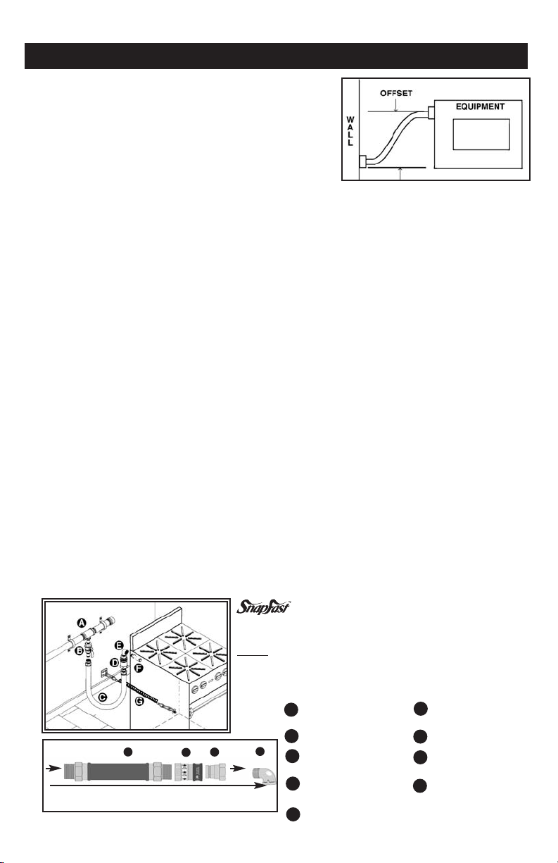
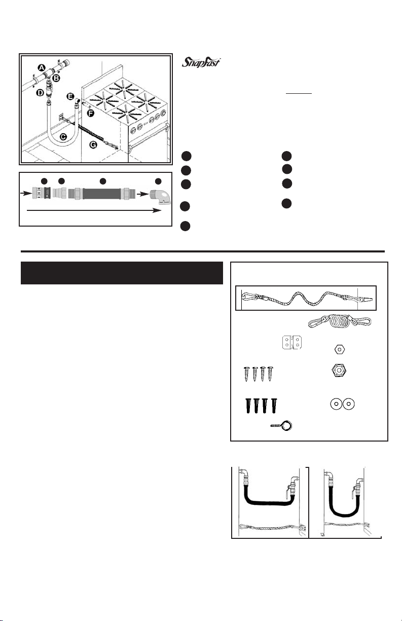
INSTALLATION INSTRUCTIONS (FIGURE 1)
1. Before proceeding, CAREFULLY read this full set of instructions,
including the CAUTION AND WARNINGS section also the
INSTALLATION RIGHTS AND WRONGS section of this
instruction booklet.
2. The manual gas shut off ball valve (B), located in the gas manifold
line (A), must be in the fully closed (off) position. If there is no gas
shut-off valve in the manifold line, the main gas supply line valve
(not shown) must be turned off. DO NOT CONTINUE
UNLESS THE GAS IS TURNED OFF.
3. Remove the gas connector and contents from the bag or box.
4. The location of the two connection end points for the gas appliance connector, the gas supply line and the
equipment stub-out – can vary greatly. It is not practical to show every possible installation combination. These
instructions include several examples of common installations. The installer must always take great care to
ensure that the connector is not kinked, twisted or torqued when installed - and that the end fittings of the
connector are not subjected to sharp bends. (Please refer to Installation Rights and Wrongs). For installations
that may result in a sharp bend, Dormont SwivelMAX
TM
gas connectors are recommended.
5. It is recommended that the main gas supply manifold be located 30''- 42'' off the ground. There should be pipe
tees pointed in the downward direction.
6. To facilitate moving equipment as close to the wall as possible, the two ends of the Dormont gas connector
should be offset to the side from each other. (+/–3'' offset recommended, see drawing 1).
7. Each piece of equipment MUST have its own approved manual shut-off valve. If there is not an accessible
manual gas shut-off valve for each piece of equipment, make sure that the gas has been shut off at the main gas
shut-off valve for each piece of equipment before continuing.
8. MANUAL SHUT-OFF VALVE INSTALLATION:
Female x Female valve ends
a. If the pipe tee is a male thread: Apply thread sealant (pipe dope) or thread tape to accessible pipe threads
located at the gas supply line. Thread the gas shut-off ball valve onto the male iron pipe and tighten wrench
tight. Locate ball valve as close as you can to the manifold leaving enough clearance to turn on and off.
Preferred valve position is vertical. (see Figure 1).
b. If the pipe tee is a female thread: Apply thread sealant (pipe dope) or thread tape to the threads of a pipe
nipple (not supplied/preferred length is three inches). Thread pipe nipple into female pipe tee off main gas
line. Then thread the shut-off valve onto the pipe nipple and tighten wrench tight.
9. WARNING: The SnapFast
TM
Quick-Disconnect coupling (D) MUST BE oriented so that the gas enters
the female (valved) coupling half and exit the male nipple half. FOLLOW the flow direction arrows
permanently marked on the coupling.
FIGURE 1
OPTION 1
QD Device Installed at the Appliance:
This installation method, commonly used in North America, shows the
quick-disconnect coupling attached at the appliance side. The nipple
MUST
always be on the appliance side, attached to the appliance stubout or external regulator. This enables the operator to move the equipment away from the wall in an equipment line-up and safely disconnect
the gas connector from the back side of the appliance.
Gas Supply Line
AA
(Gas Manifold)
BB
GAS
GAS
GAS FLOW DIRECTION
Figure 1 a
IICC
HH
EE
Gas Shut-Off Ball Valve
Safety System
CC
Connector
SnapFast
TM
DD
Disconnect
EE
90° Street Elbow
Drawing 1 - offset
TM
Gas
Quick-
Appliance Male
FF
Stub-Out
Restraining Device
GG
Quick-Disconnect
HH
Coupling (female)
Quick-Disconnect
II
Nipple (male)
Page 4

INSTALACIÓN DEL CONJUNTO DE EQUIPO CON MÚLTIPLE FRONTAL DE
ALIMENTACIÓN DOBLE
CUANDO INSTALE UN CONJUNTO DE EQUIPO CON ENTRADA DE GAS DEL MÚLTIPLE FRONTAL DE
ALIMENTACIÓN DOBLE:
¡NO UTILICE ACOPLES DE DESCONEXIÓN RÁPIDA SAFETY QUICKTMO SnapFastTMPARA ESTE TIPO DE
INSTALACIÓN!
El uso de un acople de desconexión rápida en este tipo de instalación puede ser peligroso y no se recomienda.
¡ADVERTENCIA!
A menos que las válvulas de cierre corriente arriba en ambas líneas de entrada estén completamente cerradas, la
desconexión de un acople de desconexión rápida puede provocar un flujo abierto de gas.
Se puede usar un(os) conector(es) flexible(s) Safety SystemTMsin el acople de desconexión rápida.
Todas las instrucciones de instalación en este folleto describen las instalaciones que excluyen el uso de un
regulador externo para aparato de gas. Si necesita uno, enrosque el regulador en la salida del aparato antes de
instalar el codo con rosca macho y hembra. Posteriormente, enrosque la rosca hembra del regulador y el codo
con rosca macho y hembra, usando un empalme macho a macho. Una vez que lo haga, continúe la instalación
de acuerdo a las instrucciones restantes.
Instrucciones Recomendadas de Operación:
Limpieza detrás del Equipo
I. Desconexión de la Línea de Gas
1) Apague el equipo.
2) Retire cuidadosamente el equipo de la pared, deteniéndose cuando el cable de retención esté tirante.
3) Cierre el suministro de gas al girar la palanca en la válvula esférica del gas a la posición de “cerrado” (localizada a un
lado de la línea del múltiple principal). Desconecte cualquier cordón eléctrico.
4) Desconecte la línea de gas al tirar hacia atrás la manga del acople de desconexión rápida. Tenga cuidado de no dejar
caer el acople al piso, lo cual dañaría la unidad.
5) Quite el gancho del cable de retención.
6) Retire cuidadosamente el equipo de la pared.
7) Limpie detrás del equipo, asegurándose que no entre en el acople de desconexión rápida o en la línea de gas ninguna
sustancia extraña, grasa, solución limpiadora o suciedad.
II. Reconexión de la Línea de Gas
1) Conecte nuevamente el acople de desconexión rápida al insertar el extremo del tapón (empalme) en el acople.
2) Conecte nuevamente el cable de retención.
3) Conecte nuevamente cualquier cordón eléctrico.
4) Gire la palanca de la válvula esférica del gas a la posición de “abierto”.
5) Cuidadosamente empuje el equipo hacia la pared, asegurándose que el conector de gas no se tuerza ni se doble en un
ángulo agudo. Verifique que el conector de gas no sea dañado o aplastado por el equipo si éste le pasa por encima.
6) Si se necesita, encienda nuevamente la llama del piloto. Encienda el equipo.
11
Soporte de Ingeniería de Dormont
El equipo de Ingeniería de Dormont está disponible para ayudarle con el diseño y disposición de las
instalaciones de equipo de cocina. Podemos diseñar la conexión de gas apropiada para que funcione con
su equipo y de acuerdo a las necesidades de su cocina.
Dormont ha trabajado con consultores, cadenas nacionales y fabricantes de equipo para solucionar los
problemas más difíciles de instalaciones de gas.
Los diagramas CAD anteriores son solamente algunos ejemplos del tipo de soporte técnico que ofrecemos. Para mayores detalles, comuníquese con nuestros Especialistas en Servicios al Cliente al 1-800DORMONT (367-6668).
Política de Devoluciones
No se deben hacer devoluciones a Dormont Manufacturing Company sin obtener primero un número de
autorización de devolución. No se aceptará ni acreditará ninguna devolución sin esta aprobación previa. Las
devoluciones estarán sujetas a un cargo del 25% por resurtido más cualquier cargo incurrido por el flete.
Page 5
10
EE.UU.
ANSI Z21.69/CSA 6.16
Conectores Metálicos para Aparatos
Móviles de Gas.
ANSI Z21.41/CSA 6.9
Dispositivos de Desconexión Rápida
para uso con gas combustible.
ANSI Z21.15/CGA 9.1
Válvula Manual de Gas para
Aparatos, Válvulas para Conectores
de Aparatos y Válvulas para
Mangueras.
CANADA
Certificaciones
CANADA
CR-92-009
Conectores Giratorios para uso
con Conectores de Aparatos
Móviles de Gas.
Aprobaciones
EE.UU.
Diseño certificado de acuerdo a ANSI/U.L. 567,
Conectores de Tubería para Líquidos
Combustibles e Inflamables y Gas
LP. Para uso con gas natural y
propano.
EE.UU.
NSF Internacional
Equipo especial criterio C-2.
(Solamente en los modelos
recubiertos con PVC).
CANADA
Aprobado por la Junta de Examinadores Estatales de Plomeros y
Trabajadores del Gas del Estado Mancomunado de Massachussets. La
longitud del conector no debe sobrepasar los 91.4 cm y no se permiten
válvulas de palanca.
Ciudad de Nueva York MEA# 274-02-E
Conformidad
CANADA
CSA B149.1
Código de Instalación de Gas Natural y
Propano.
ANSI Z223.1/NFPA 54
Garantía
Garantías y Recursos
a. Garantía. El Vendedor le garantiza al Comprador que posee y traspasa el título de
mercancía de los conectores comerciales de gas aquí vendidos. Además el
Vendedor le garantiza al Comprador que el conector comercial de gas del
Vendedor estará libre de defectos en los materiales y mano de obra que puedan
provocar una fuga de gas durante la vida útil del equipo al cual sea originalmente
conectado o instalado el conector comercial de gas. (Garantía limitada de
por vida).
El Vendedor le garantiza al Comprador que los artículos y componentes fabricados
por el Vendedor que no sean los conectores comerciales de gas estarán libres de
defectos en los materiales y mano de obra por un período de cinco (5) años a partir
de la fecha de entrega al Comprador. Para los artículos no fabricados por el
Vendedor, la única garantía que se extiende es la del fabricante o proveedor de los
mismos, si la hubiere.
b. Exclusiones y Condiciones. Las obligaciones del Vendedor con respecto a las
garantías y recursos expresos, aquí contenidos, están condicionados a lo siguiente:
(i) La responsabilidad del Vendedor y el único recurso del Comprador está limitado
expresamente al reemplazo por parte del Vendedor del conector de gas defectuoso
u otros bienes a expensas del Vendedor (excluyendo mano de obra y flete); se
entiende que dicho reemplazo se efectuará solamente después de la devolución del
artículo defectuoso de acuerdo a las instrucciones de embarque del Vendedor y con
la autorización de devolución, y estará sujeta a la inspección por parte del
Vendedor; (ii) El Comprador no asignará sus derechos bajo estas garantías expresas
Condiciones
Limitaciones de Responsabilidad.
Las siguientes limitaciones de la responsabilidad del Vendedor son reconocidas por las
partes como justas y razonables y se aplicarán a cualquier acto u omisión mencionadas
posteriormente y a cualquier incumplimiento de este contrato del cual forman parte estos
términos y condiciones.
Descargo de Daños
En ningún caso será responsable el Vendedor por daños especiales, indirectos, consecuenciales o incidentales que resulten bajo contrato, garantía, perjuicio, negligencia,
responsabilidad estricta o cualquier otra teoría de responsabilidad. Tales daños incluyen,
pero no se limitan a la pérdida de ganancias, pérdida del uso de los bienes, daño a la
propiedad y reclamaciones de terceras partes. Algunos Estados no permiten la exclusión o
limitación de daños incidentales o consecuenciales o cualquier limitación en la duración
de la garantía implícita, así que la exclusión o limitación anteriormente mencionada
podría no aplicarse a usted. Esta garantía le otorga derechos legales específicos y usted
podría tener también otros derechos, los cuales varían de Estado a Estado.
EE.UU.
EE.UU.
– Código Nacional de Gas Combustible.
y cualquier intento de asignación anulará dichas garantías, pero no cualquier
descargo o limitación, y que los bienes serán vendidos TAL COMO ESTÁN y
(iii) todos los conectores comerciales de gas y otros bienes, a su arribo, serán
inspeccionados cuidadosamente por el Comprador buscando daños, serán instalados por personas capacitadas y certificadas como profesionales en dichas instalaciones y serán instaladas, usadas, reparadas y mantenidas por el Comprador de
acuerdo a los códigos o reglamentos locales, normas fijadas por el Instituto
Norteamericano de Normas Nacionales y / o las Normas de la Asociación
Norteamericana de Gas. Los conectores comerciales de gas y otros bienes estarán
garantizados en conjunto con la instalación original solamente y las garantías y
recursos expresos aquí contenidos, no se aplicarán a, y serán nulos sin mayor consecuencia, daño y / o falla de los conectores comerciales de gas y otros bienes, provocados por o como resultado del flete, manejo, instalación, alteración o reparación
inapropiados o no autorizados; mal uso, abuso u otros incidentes o condiciones que
no sean el uso normal; la aplicación o conformidad con los códigos o reglamentos
locales no dados a conocer previamente al Vendedor, o accidente u otro incidente.
Descargo de Garantías Implícitas
El Vendedor no otorga ninguna garantía excepto aquéllas contenidas
expresamente aquí. El Vendedor niega cualquier otra garantía implícita por ley, costumbre de la industria, trato o desempeño, incluyendo,
pero sin limitarse a, las garantías implícitas de comerciabilidad e idoneidad para un propósito en particular.
Notificación y Tiempo de Reclamación
(i) El Comprador declara estar de acuerdo en revisar e inspeccionar todos los productos
contra la documentación de envío y a buscar daños o faltantes al momento de recibir los
bienes en su destino; (ii) Cada reclamación por pérdida, daño en tránsito u otra causa visible a la inspección, se hará con el transportista. Las reclamaciones por faltantes deben
hacerse en los siguientes cinco (5) días después de la recepción; (iii) Las partes renuncian
expresamente al estatuto de limitaciones y declaran estar de acuerdo que cualquier procedimiento legal por cualquier incumplimiento de este contrato será renunciado a menos
que se efectúe dentro de los dos (2) años siguientes al motivo de la acción.
Page 6
9a. NOTE: There are two options for the orientation of the quick-disconnect couplings: OPTION #1– quickdisconnect at the appliance. OPTION #2– quick-disconnect at the piping system.
10. OPTION #1: Quick-Disconnect attached at the appliance side (Refer to Figure 1).
Gas Supply Side:
A. Apply thread sealant (pipe dope) or thread tape to the threads at one end of the gas connector.
B. Thread this end of the gas connector into the gas shut-off valve and tighten with wrenches.
Appliance Side:
C. Apply thread sealant (pipe dope) or thread tape to the appliance’s male stub-out (F), and thread street
elbow (E) onto male stub-out, and tighten with wrenches. The location of both the equipment stub-out
and the tees for the gas supply line manifold can vary greatly.
D. Apply thread sealant (pipe dope) or thread tape to male street elbow (E) threads.
E. Separate the quick-disconnect coupling male end or nipple (I) from the female end or coupling (H).
Thread the male nipple (I) onto the street elbow (E) and tighten. NOTE: The quick-disconnect MUST
BE ORIENTED so that the gas enters the coupling half and exits the nipple half of the quick-disconnect.
Installation personnel MUST follow the flow direction arrows permanently marked on the coupling.
F. Apply thread sealant (pipe dope) or thread tape to the male threads of the gas connector. Thread quick-
disconnect coupling onto the gas connector threads. Tighten.
G. Connect quick-disconnect female coupling (H) to the male nipple (I). (Figure 1 a).
H. Check tightness of all connections. Leak test in accordance with accepted testing procedures.
I. After installation of the connector, carefully push the appliance back to its normal operating position.
Check that the connector is not kinked, over bent, or caught under the equipment casters.
11. OPTION #2:
(Refer to Figure 2 on the next page).
WARNING: If you decide to select an Option 2 installation (quick-disconnect at the gas supply side), the
female coupling part of the quick-disconnect coupling must be upstream and attached to the gas supply.
Quick-Disconnect attached at the gas supply line side—“Reverse Quick-Disconnect.”
Gas Supply Side:
A. Apply thread sealant (pipe dope) or thread tape to the threads at one end of the gas connector.
B. Thread the gas connector end into the quick-disconnect male nipple (K). Tighten with wrenches.
C. Separate the quick-disconnect female coupling (J) from the male nipple (K). (I). (Figure 2 a).
D. Apply thread sealant (pipe dope) or thread tape to the valve nipple.
E. Thread the quick-disconnect female coupling onto the threads of the pipe nipple from the gas shut-off valve.
Tighten with wrench.
Appliance Side:
F. Apply thread sealant (pipe dope) or thread tape to the appliance’s stub-out (F) and thread the elbow onto
stub-out. Tighten.
G. Apply thread sealant (pipe dope) or thread tape to the male threads of the street elbow. Insert
male threads into f x f threaded coupling (not included).
H. Apply thread sealant (pipe dope) or thread tape to the gas connector threads. Thread hose into the
coupling. Tighten with wrench.
I. Connect quick-disconnect male nipple (K) to the female coupling (J).
J. Check tightness of all connections. Leak test in accordance with accepted testing procedures.
K. After installation of the connector, carefully push the appliance back to its normal operating position.
Check that the connector is not kinked, over bent, or caught under the equipment casters.
3
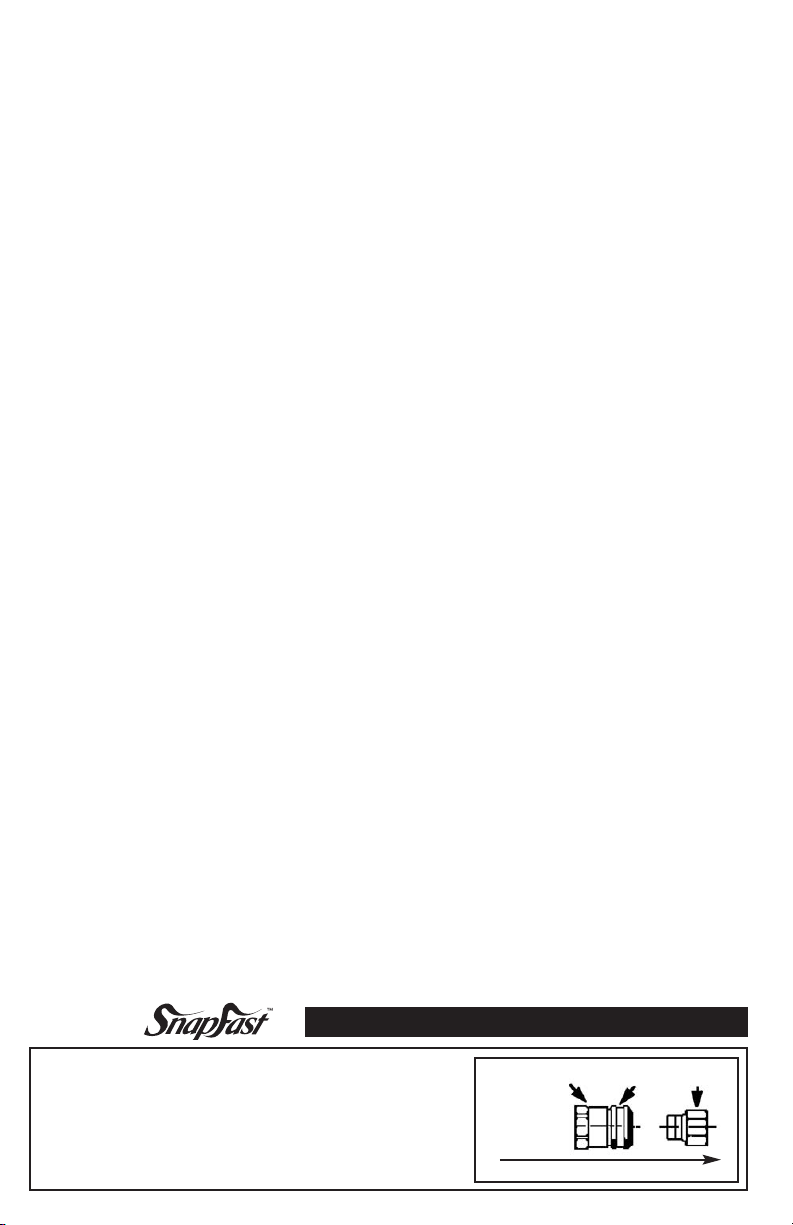
Operating Instructions
TO CONNECT: Push nipple straight into coupling until sleeve snaps
forward against retaining ring. Open shut-off valve to turn on gas.
TO DISCONNECT: Close shut off valve to turn off gas. Retract sleeve
and pull out nipple.
IMPORTANT: COUPLING IS NOT TO BE USED AS THE PRIMARY SHUT OFF.
Coupling Sleeve Nipple
GAS FLOW DIRECTION
Page 7
4
FIGURE 2
OPTION 2*
QD Device Installed at the Gas Supply
This installation method, commonly used in Europe,
shows the quick-disconnect coupling attached at the
gas supply side. The coupling MUST always be on the
gas supply side, attached to the supply side piping. This
enables the operator to move the equipment away from
the wall in an equipment line-up and safely disconnect
the gas connector from the gas supply line.
Appliance Male Stub-Out
FF
Restraining Cable
GG
Quick-Disconnect Coupling
JJ
(female)
Quick-Disconnect Nipple
KK
(male)
GAS
KK
GAS FLOW DIRECTION
Figure 2 a
CCJJ
EE
Restraining Cable
Installation Instructions
AA
House Pipe Inlet
BB
Full Port Gas Ball Valve
Safety System
CC
Connector
TM
SnapFast
DD
Disconnect Coupling
EE
90° Elbow
Quick-
TM
Gas
Restraining Cable Installation
This Restraining Device Must Always be
Reconnected When the Appliance Is in Service
The restraining device should be disconnected for movement,
such as, servicing or cleaning, only after gas has been shut
off and the connector has been disconnected!
Reconnect restraining cable before reconnecting the gas connector
and moving back to its original position.
A - Restraining Cable with
B - Two Snap Hooks
C - Staple Bracket
D - 1'' #10 Screws (4)
G - 1/4'' Hex Nut
H - 1/4'' Nylon Lock Nut
RESTRAINING CABLE:
1. Restraining Device should be installed parallel (in line with
the gas appliance connector.)
2. Attach the staple bracket (C) to a stud in the wall, using
the four 1'' #10 screws (D) and the plastic anchors (E)
if needed.
3. Locate a structural area (frame) on the rear side of the
equipment that is in line with the wall attachment. Drill a
1/4'' diameter hole. Use caution when drilling hole, so that
internal components are not damaged.
4. Thread the hex nut (G) and a washer (I) onto the
eye-bolt (F). Slide one washer onto the nut. Slide the
eye-bolt through the drilled hole and place a washer (I) and
the nylon lock nut (H) onto the eye-bolt on the inside
frame of the equipment and tighten securely.
5. Attach one of the snap hooks (B) to the staple bracket on
the wall (Step 2 above) and the other to the eye-bolt
(Steps 3 and 4 above).
E - Plastic Anchors (4)
F - Eye-Bolt
WRONG RIGHT
Set the length of the restraining device so that the
connector is not kinked when the restraining device is
fully extended.
I - 1/4'' x 1 1/4'' Washers (2)
Note:
For adjustable restraining devices, the cable is manufactured to be shorter than the length of the gas connector.
Page 8
Aciertos y Errores en la Instalación
ERROR
Evite las vueltas pronunciadas y acodados cuando retire el equipo de la pared.
Retirar al máximo acodará los extremos, aún si están instalados apropiadamente y
reducirá la vida útil del conector.
ACIERTO
Retiro mínimo del equipo de la pared que permita el acceso a la Desconexión
Rápida Safety Quik
TM
.
99
ERROR ACIERTO
VUELTAS PRONUNCIADAS: Instale la manguera de metal
para la columna desplazable con una vuelta sencilla, natural. Evite
las vueltas pronunciadas que forcen y tuerzan la manguera de metal
hasta un punto de falla prematura en el acople.
ERROR ACIERTO
FATIGA: Mantener el diámetro mínimo o mayor de vuelta
entre los acoples crea vueltas dobles provocando fatiga de trabajo
en los accesorios.
Nota: El aparato debe estar desconectado antes de moverlo al máximo.
Un movimiento mínimo es aceptable
para dejarlo conectado.
Pulgadas D.I. del conector nominal
1/2” 150,000 106,000 86,600
3/4” 290,900 215,000 173,900
1” 581,800 442,700 347,800
1 1/4” 1,075,000 817,500 634,000
Pulgadas D.I. del conector nominal
1/2” 87,000 68,000 55,000
3/4” 232,000 180,000 139,000
1” 414,000 334,000 279,000
1 1/4” 699,000 541,000 419,000
Pulgadas D.I. del conector nominal
1/2'' 145,600 102,900 84,000
3/4'' 282,400 208,700 168,800
1'' 564,800 429,800 337,600
1- 1/4 1,043,600 793,600 615,500
NOTA: Cuando use una caída de presión de columna de agua de 0.2, la capacidad puede ser determinada al multiplicar la cifra anterior por
0.632. Para capacidades y condiciones diferentes de las anotadas, comuníquese con su proveedor de servicio de gas.
CAPACIDAD CON EL DISPOSITIVO DE DESCONEXION RAPIDA
Nota: Nunca inserte objetos tales como
destornilladores, sondas, etc. en la
válvula SnapFastTM. El asiento de la
válvula puede dañarse o descentrarse.
CAPACIDAD DEL CONECTOR
Capacidad Recta – BTU por Hr. (w)
0.64 Sp Gr 1000 BTU por Pie
Caída de Presión de Columna de Agua
2 pies 4 pies 6 pies
2 pies 4 pies 6 pies
CAPACIDAD CON LA VALVULA MANUAL DE CIERRE
2 pies 4 pies 6 pies
ERROR ACIERTO
TORCEDURA: Los acoples y la manguera deben ser instalados en el
mismo plano vertical. No hacerlo puede provocar torceduras y esfuerzos mayores que provoquen la falla prematura.
ERROR ACIERTO
AUTO DRENAJE: En todas las instalaciones donde no se nece-
sita el "auto drenaje", conecte la manguera de metal en un lazo
vertical. No conecte la manguera de metal horizontalmente a
menos que sea necesario el "auto drenaje", luego use un apoyo en
el plano inferior.
NOTA: El Dispositivo de
Retención es obligatorio en
todos los tipos de aparatos
móviles de gas.
3
Gas a 0.5 pulg.
NOTA: La capacidad fue determinada bajo condiciones de prueba especificadas por ANSI Z21.69
Page 9

8
Lazo de Combinación
Pared: Suministro de Gas de Alto Nivel
Equipo: Conexión de Entrada Posterior Baja
Recomendación:
Instalación del Kit SwivelMAX
Doble Modelo # 1675KIT2S48
de Dormont
TM
Pared: Suministro de Gas de Alto Nivel
Equipo: Conexión de Entrada Posterior Alta
Recomendación:
Instalación
Válvula de Protección de Desconexión
Rápida Safety QuikTMcon accesorios
SwivelMAXTMDobles de Dormont
Instalación Modelo #1675KITCF2S48
Safety QuikTMcon SwivelMAXTMSencillo
A. Aplique un sellador de roscado (barniz para tubería) o cinta para roscado en las roscas localizadas en
un extremo del conector de gas. Inserte la rosca macho del conector de gas en la rosca hembra del
accesorio SwivelMAXTM.
Lado del Suministro de Gas:
B. Aplique un sellador de roscado (barniz para tubería) o cinta para roscado en la rosca macho del accesorio
SwivelMAXTM. Separe el empalme Safety QuikTM(macho) del acople Safety QuikTM(hembra).
Enrosque el extremo macho del SwivelMAXTMen el empalme Safety QuikTM. Apriete.
Lado del Aparato:
C. Aplique un sellador de roscado (barniz para tubería) o cinta para roscado en la salida macho del aparato.
Enrosque el codo de rosca macho y hembra en la salida.
D. Aplique un sellador de roscado (barniz para tubería) o cinta para roscado en la rosca macho del codo de
rosca macho y hembra. Inserte las roscas macho en el acople de rosca hembra x hembra (no incluido).
E. Aplique un sellador de roscado (barniz para tubería) o cinta para roscado en las roscas macho del conector
de gas. Inserte la rosca en el acople de rosca hembra. Apriete.
F. Inserte el empalme Safety QuikTMen el acople Safety QuikTMpara completar la conexión.
G. Revise el apretado de todas las conexiones. Busque fugas de acuerdo a los procedimientos de prueba acep-
tados. Enjuague.
H. Después de la instalación del conector, empuje con cuidado el aparato de regreso a su posición normal de
operación. Verifique que la conexión no esté acodada, muy doblada o atrapada bajo las ruedas del equipo.
Page 10

Installation Instructions for Gas Appliance Connector
5
SWIVELMAX
CONNECTORS ONLY.
1. Do not conceal swivel within or run through walls, floors or partitions.
2. For use on piping systems having fuel gas pressures not exceeding 1/2 psig.
3. Install downstream of the gas supply piping manual shut-off valve ONLY.
4. Use thread sealant (pipe dope) only when installing a SwivelMAX
DO NOT USE TEFLON TAPE ON THE SWIVEL.
DO NOT OVER TIGHTEN.
TM
FITTINGS ARE DESIGN CERTIFIED FOR USE WITH DORMONT GAS
TM
fitting.
Single SwivelMAXTMAppliance Connection:
NOTE: The SwivelMAXTMis attached to the gas supply end of
the connector.
Gas Supply Side:
A. Apply thread sealant (pipe dope) to the threads at one end of the gas connector.
Thread this end of the gas connector into the female threads of the
SwivelMAXTMfitting.
B. Apply thread sealant (pipe dope) to the male SwivelMAXTMthreads. Thread this end of the gas
connector into the female threads of the gas shut-off valve and tighten with wrenches.
Appliance Side: (Refer to Figure 1 and 1 a)
C. Apply thread sealant (pipe dope) or thread tape to the appliance’s male stub-out (F-Figure 1) and
thread street elbow (E) onto male stub-out. The location of both the equipment stub-out and the
tees for the gas supply line manifold can vary greatly.
D. Apply thread sealant (pipe dope) or thread tape to male street elbow (E) threads.
E. Separate the quick-disconnect (male) nipple (I-Figure 1 a) from the coupling (J). Thread the male
nipple (I) onto the street elbow (E) and tighten. NOTE: The quick-disconnect MUST BE
ORIENTED so that the gas enters the coupling half and exits the nipple half of the quick-
disconnect. Installation personnel MUST follow the flow direction arrows permanently marked on
the coupling.
F. Apply thread sealant (pipe dope) or thread tape to the threads at the appliance end of the gas
connector. Thread this end of the gas connector into the female threads of the quick-disconnect
coupling (H). Tighten.
G. Connect quick-disconnect female coupling (H) to the male nipple (I).
H. Check tightness of all connections. Leak test in accordance with accepted testing procedures.
Rinse.
I. After installation of the connector, carefully push the appliance back to its normal operating
position. Check that the connector is not kinked, over bent, or caught under the
equipment casters.
Double SwivelMAXTMAppliance Connection:
Gas Supply Side:
A. Follow the Single SwivelMAXTMinstallation instructions (A-B).
Appliance Side:
B. Apply thread sealant (pipe dope) to the male threads of the gas connector.
C. Insert male ends of gas connector into female threads of the SwivelMAXTMfitting. Tighten
D. Apply thread sealant (pipe dope) to the male threads of the SwivelMAXTM.
E. Insert male threads of SwivelMAXTMinto the quick-disconnect coupler (female) of the SnapFast
quick-disconnect fitting. Tighten with wrench.
F. Continue installation following the Single SwivelMAXTMinstallation instructions (C-E and G-I).
Page 11

6
Installation Examples
VERTICAL LOOP
Wall: Medium Level Gas Supply
Equipment: Rear High Inlet Connection
RECOMMENDATION:
Dormont Double Swivel Kit Installation
Model #1675KIT2S48
HORIZONTAL LOOP
Wall: Floor Level Gas Supply
Equipment: Rear Low Inlet Connection
RECOMMENDATION:
Dormont Single Swivel Kit Installation
Model #1675KITS48
Installation Instructions for Gas Appliance Connector
Installing a Safety QuikTMQuick-Disconnect
Protection Valve:
NOTE: THE SAFETY QUIK
BALL VALVE THAT IS REQUIRED TO BE INSTALLED AT THE GAS SUPPLY MANIFOLD
FOR EACH PIECE OF COOKING EQUIPMENT.
DO NOT INSTALL AT THE EQUIPMENT END OF THE GAS CONNECTOR.
IT MUST BE INSTALLED AT THE OUTLET OF THE GAS SUPPLY PIPING SYSTEM
UPSTREAM OF THE CONNECTOR!
Gas Side:
A. Apply thread sealant (pipe dope) or thread tape to the male threads of the drop off on the
gas manifold.
B. Make sure the handle of the Safety Quik shut-off valve is in the OFF position.
C. Attach the Safety Quik valve to the male manifold drop. Tighten with wrench.
D. Remove the nipple of the Safety Quik by pulling back on the safety sleeve collar when the
valve is in the off position.
E. Apply pipe dope or thread sealant tape to the male threads of the gas connector.
F. Insert the male threads into the Safety Quik nipple. Tighten with wrench.
Appliance Side:
G. Apply thread sealant (pipe dope) or thread tape to the appliance’s male stub-out and thread street
elbow onto male stub-out. The location of both the equipment stub-out and the tees for the gas
supply line manifold can vary greatly.
H. Attach threaded coupling, f x f (not included) to the street elbow. Tighten with wrench.
I. Apply thread sealant (pipe dope) to the male threads at the appliance end of the gas connector.
Tighten with wrench.
J. Insert male gas connector threads into the female threaded coupling. Tighten with wrench.
K. After installation, check gas connections for leaks in accordance with accepted testing procedures.
Rinse off solution after test.
TM
QUICK-DISCONNECT PROTECTION VALVE IS THE GAS
Page 12

Cómo Usar la Válvula de Protección de Desconexión Rápida Safety Quik
PARA DESCONECTAR:
1. Gire la palanca de giro fácil de la válvula a la posición de cerrado (Diagrama 1). La palanca
debe estar perpendicular al conector de gas del aparato.
2. Empuje la Manga de Seguridad hacia la palanca. Esto hará que la unidad se desconecte.
NOTA:El conector de gas del aparato no debe ser desconectado hasta que la válvula se
encuentre en posición de cerrado.
PARA RECONECTAR:
1. Empuje firmemente el empalme de desconexión rápida fijado al conector de gas del aparato,
dentro del cuerpo del acople (Diagrama 2). Esto permitirá que la manga de seguridad regrese a
su posición original.
2. Gire la palanca de la válvula a la posición de abierto para permitir que el gas fluya al aparato
(paralelo con el conector de gas del aparato).
7
TM
NOTA: La válvula de gas no puede ser abierta hasta que el conector de gas del aparato esté fijo
de manera apropiada.
(Diagrama 1) Posición de Cerrado
(Diagrama 2) Posición de Abierto
Válvula de
Cierre
Manga de
Empalme
Acople
Seguridad
Flujo de GAS
Safety QuikTMcon SwivelMAXTMDoble
A. Aplique un sellador de roscado (barniz para tubería) en las roscas localizadas en ambos extremos
del conector de gas. Inserte la rosca macho del conector de gas en la rosca hembra del accesorio
SwivelMAX
Lado del Suministro de Gas:
B. Aplique un sellador de roscado (barniz para tubería) en la rosca macho del accesorio
SwivelMAX
Enrosque el extremo macho del SwivelMAX
Lado del Aparato:
C. Aplique un sellador de roscado (barniz para tubería) en la salida macho del aparato. Enrosque el
codo de rosca macho y hembra en la salida.
D. Aplique un sellador de roscado (barniz para tubería) o cinta para roscado en la rosca macho del
codo de rosca macho y hembra. Inserte las roscas macho en el acople de rosca hembra x hembra
(no incluido).
E. Aplique un sellador de roscado (barniz para tubería) en la rosca macho del SwivelMAX
la rosca en el acople de rosca hembra. Apriete.
F. Inserte el empalme Safety Quik
G. Revise el apretado de todas las conexiones. Busque fugas de acuerdo a los procedimientos de prueba
aceptados. Enjuague.
H. Después de la instalación del conector, empuje con cuidado el aparato de regreso a su posición nor-
mal de operación. Verifique que la conexión no esté acodada, muy doblada o atrapada bajo las
ruedas del equipo.
TM
en cada extremo del conector.
TM
. Separe el empalme Safety QuikTM(macho) del acople Safety QuikTM(hembra).
TM
en el acople Safety QuikTMpara completar la conexión.
TM
en el empalme Safety QuikTM. Apriete.
TM
. Inserte
Page 13

6
Ejemplos de Instalación
LAZO VERTICAL
Pared: Suministro de Gas de Nivel Medio
Equipo: Conexión de Entrada Posterior Alta
RECOMENDACIÓN:
Instalación del Kit Swivel Doble de Dormont
Modelo #1675KIT2S48
LAZO HORIZONTAL
Pared: Suministro de Gas a Nivel de Piso
Equipo: Conexión de Entrada Posterior Baja
RECOMENDACIÓN:
Instalación del Kit Swivel Sencillo de
Dormont
Modelo #1675KITS48
Instrucciones de Instalación del Conector del Aparato de Gas
Instalación de la Válvula de Protección de
Desconexión Rápida Safety QuikTM:
NOTA: LA VALVULA DE PROTECCION DE DESCONEXION RAPIDA SAFETY QUIKTMES
UNA VALVULA ESFERICA DE GAS QUE SE NECESITA INSTALAR EN EL MULTIPLE DEL
SUMINISTRO DE GAS PARA CADA PIEZA DEL EQUIPO DE COCINA.
NO LA INSTALE EN EL EXTREMO DEL EQUIPO DEL CONECTOR DE GAS.
¡DEBE INSTALARSE EN LA SALIDA DEL SISTEMA DE TUBERIA DEL SUMINISTRO DE
GAS CORRIENTE ARRIBA DEL CONECTOR!
Lado del Gas:
A. Aplique un sellador de roscado (barniz para tubería) o cinta para roscado en las roscas macho de la
salida del múltiple de gas.
B. Asegúrese que la palanca de la válvula de cierre Safety Quik esté en posición de CERRADO.
C. Fije la válvula de seguridad Safety Quik a la entrada macho del múltiple. Apriete con una llave.
D. Quite el empalme del Safety Quik al tirar hacia atrás del collar de la manga de seguridad cuando la
válvula esté en posición de cerrado.
E. Aplique barniz para tubería o cinta para roscado en las roscas macho del conector de gas.
F. Inserte la rosca macho en el empalme Safety Quik. Apriete con una llave.
Lado del Aparato:
G. Aplique sellador de roscado (barniz para tubería) o cinta para roscado en la salida macho del apara-
to y enrosque el codo de rosca macho y hembra en la salida macho. Puede variar mucho la ubi-
cación tanto de la salida del equipo como de la T para el múltiple de la línea de suministro de gas.
H. Fije el acople roscado hembra x hembra (no incluido) en el codo de rosca macho y hembra.
Apriete con una llave.
I. Aplique un sellador de roscado (barniz para tubería) en las roscas macho localizadas en el extremo
del aparato del conector de gas. Apriete con una llave.
J. Inserte la rosca macho del conector de gas en el acople con rosca hembra. Apriete con una llave.
K. Después de la instalación, busque fugas de gas en las conexiones de acuerdo a los procedimientos
de prueba aceptados. Enjuague la solución después de la prueba.
Page 14

How to Use the Safety QuikTMQuick-Disconnect Protection Valve
TO DISCONNECT:
1. Turn the easy turn valve handle to the off position (Diagram 1). Handle should be
perpendicular to the gas appliance connector.
2. Push the Safety Sleeve toward the handle. This will cause the unit to disconnect.
NOTE: The gas appliance connector cannot be disconnected until the valve is in the
off position.
TO RECONNECT:
1. Firmly push the quick-disconnect nipple, attached to the gas appliance connector, into the
coupling body (Diagram 2). This will allow the safety sleeve to return to its original position.
2. Turn the valve handle to the on position to allow gas flow to the appliance (parallel with the
gas appliance connector).
7
NOTE: The gas valve cannot be turned to the on position until the gas appliance connector
is properly attached.
(Diagram 1) Off Position
Shut-Off
Valve
Safety
Sleeve
Nipple
(Diagram 2) On Position
Coupling
GAS Flow
Safety QuikTMwith Double SwivelMAX
A. Apply thread sealant (pipe dope) to the threads of the gas connector at both ends. Insert the male
threads of the gas connector into the female threads of the SwivelMAXTMfitting on each end of
the connector.
TM
Gas Supply Side:
B. Apply thread sealant (pipe dope) to the male threads of a SwivelMAXTMfitting. Separate the
Safety QuikTMnipple (male) from the Safety QuikTMcoupling (female). Thread the male end of the
SwivelMAXTMinto the Safety QuikTMnipple. Tighten.
Appliance Side:
C. Apply thread sealant (pipe dope) to the male stub-out of the appliance. Thread the street elbow
onto the stub-out.
D. Apply thread sealant (pipe dope) or thread tape to the male threads of the street elbow. Insert male
threads into f x f threaded coupling (not included).
E. Apply thread sealant (pipe dope) to the male threads of the SwivelMAXTM. Insert threads into
female threaded coupling. Tighten.
F. Insert Safety QuikTMnipple into Safety QuikTMcoupling to complete the connection.
G. Check tightness of all connections. Leak test in accordance with accepted testing procedures.
Rinse.
H. After the installation of the connector, carefully push the appliance back to its normal operating
position. Check that the connection is not kinked, over bent, or caught under the
equipment casters.
Page 15

8
Combination Loop
Wall: High Level Gas Supply
Equipment: Rear Low Inlet Connection
Recommendation:
Dormont Double SwivelMAXTMKit
Installation Model #1675KIT2S48
Wall: High Level Gas Supply
Equipment: Rear High Inlet Connection
Recommendation:
Installation
Dormont Safety QuikTMQD Protection
Valve with Double SwivelMAXTMFittings
Installation Model #1675KITCF2S48
Safety QuikTMwith Single SwivelMAX
A. Apply thread sealant (pipe dope) or thread tape to the threads of the gas connector at one end.
Insert the male threads of the gas connector into the female threads of the SwivelMAXTMfitting.
TM
Gas Supply Side:
B. Apply thread sealant (pipe dope) or thread tape to the male threads of a SwivelMAXTMfitting.
Separate the Safety QuikTMnipple (male) from the Safety QuikTM coupling (female). Thread the
male end of the SwivelMAXTMinto the Safety QuikTMnipple. Tighten.
Appliance Side:
C. Apply thread sealant (pipe dope) or thread tape to the male stub-out of the appliance. Thread the
street elbow onto the stub-out.
D. Apply thread sealant (pipe dope) or thread tape to the male threads of the street elbow. Insert male
threads into f x f threaded coupling (not included).
E. Apply thread sealant (pipe dope) or thread tape to the male threads of the gas connector. Insert
threads into female threaded coupling. Tighten.
F. Insert Safety QuikTMnipple into Safety QuikTMcoupling to complete the connection.
G. Check tightness of all connections. Leak test in accordance with accepted testing procedures.
Rinse.
H. After the installation of the connector, carefully push the appliance back to its normal operating
position. Check that the connection is not kinked, over bent, or caught under the
equipment casters.
Page 16

Instrucciones de Instalación del Conector del Aparato de Gas
LOS ACCESORIOS SWIVELMAX™ESTAN CERTIFICADOS EN SU DISEÑO PARA
USARSE SOLAMENTE CON CONECTORES DE GAS DORMONT.
1. No esconda el accesorio en, ni lo pase por, paredes, pisos o divisiones.
2. Para usarse en sistemas de tubería que tengan presiones de gas combustible no mayores de
1/2 psig.
3. Instale SOLAMENTE corriente abajo de la válvula manual de cierre del suministro de gas.
4. Cuando instale un accesorio SwivelMAX™ use sellador de roscado (barniz para tubería)
solamente.
NO USE CINTA DE TEFLON EN EL ACCESORIO.
NO SOBREAPRETAR.
Conexión del Aparato con SwivelMAX™ Sencillo:
NOTA: El SwivelMAX™ está fijo al extremo del suministro de gas
del conector.
Lado del Suministro de Gas:
A. Aplique un sellador de roscado (barniz para tubería) en las roscas localizadas en el
extremo del conector de gas. Inserte este extremo del conector de gas en la rosca
hembra del accesorio SwivelMAX™.
B. Aplique un sellador de roscado (barniz para tubería) en la rosca macho del SwivelMAX™.
Enrosque este extremo del conector de gas en la rosca hembra de la válvula de cierre de gas y apriete
con una llave.
Lado del Aparato: (Vea la Figura 1 y 1a)
C. Aplique sellador de roscado (barniz para tubería) o cinta para roscado en la salida macho del aparato
(F – Figura 1) y enrosque el codo de rosca macho y hembra (E) en la salida macho. Puede variar mucho
la ubicación tanto de la salida del equipo como de la T para el múltiple de la línea de suministro de gas.
D. Aplique un sellador de roscado (barniz para tubería) o cinta para roscado en las roscas macho del codo de
rosca macho y hembra (E).
E. Separe el empalme de desconexión rápida (macho) (I – Figura 1a) del acople (J). Enrosque el empalme
macho (I) en el codo de rosca macho y hembra (E) y apriete. NOTA: El acople de desconexión rápida
DEBE ESTAR ORIENTADO de tal manera que el gas entre por la parte del conector y salga por el
empalme. El personal de instalación DEBE seguir las flechas de dirección del flujo que están marcadas
indeleblemente en el acople.
F. Aplique un sellador de roscado (barniz para tubería) o cinta para roscado en las roscas localizadas en el
extremo del conector de gas. Inserte este extremo del conector de gas en la rosca hembra del acople de
desconexión rápida (H). Apriete.
G. Conecte el acople hembra de desconexión rápida (H) en el empalme macho (I).
H. Revise el apretado de todas las conexiones. Busque fugas de acuerdo a los procedimientos de prueba acep-
tados. Enjuague.
I. Después de la instalación del conector, empuje con cuidado el aparato de regreso a su posición normal de
operación. Verifique que el conector no esté acodado, muy doblado o atrapado bajo las ruedas del equipo.
5
Conexión del Aparato con SwivelMAX™ Doble:
Lado del Suministro de Gas:
A. Siga las instrucciones de instalación del SwivelMAX™ Sencillo (A - B).
Lado del Aparato:
B. Aplique un sellador de roscado (barniz para tubería) en la rosca macho del conector de gas.
C. Inserte el extremo macho del conector de gas en la rosca hembra del accesorio SwivelMAX™.
Apriete
D. Aplique un sellador de roscado (barniz para tubería) en la rosca macho del SwivelMAX™.
E. Inserte la rosca macho del SwivelMAX™ en el acople de desconexión rápida (hembra) del acceso-
rio de desconexión rápida SnapFast. Apriete con una llave.
F. Continúe la instalación siguiendo las instrucciones de instalación del SwivelMAX™ Sencillo
(C – E y G - I).
Page 17

4
FIGURA 2
OPCIÓN 2*
Dispositivo de Desconexión Rápida
Instalado en el Suministro de Gas
Este método de instalación, usado comúnmente en
Europa, muestra el acople de desconexión rápida fijo en
el lado del suministro de gas. El acople DEBE estar
siempre en el lado del suministro de gas, fijo a la
tubería del lado del suministro. Esto le permite al operador alejar el equipo de la pared en un conjunto de
equipo y a desconectar con seguridad el conector de gas
de la línea de suministro de gas.
Entrada de la Tubería de la
AA
Casa
Válvula Esférica de Gas de
GAS
KK
DIRECCION DEL FLUJO DE GAS
CCJJ
Figura 2 a
BB
EE
Puerto Completo
Conector de Gas Safety
CC
System
Acople de desconexión rápida
DD
SnapFast
Codo a 90°
EE
Instrucciones de Instalación del
Cable de Retención
Este dispositivo de retención debe estar
conectado siempre que el aparato esté
El dispositivo de retención debe ser
desconectado para mover el aparato, por
ejemplo para el mantenimiento y limpieza,
¡únicamente después de que el gas haya sido
cerrado y se haya desconectado el conector!
Vuelva a conectar el cable de retención antes de volver a conectar
en servicio
TM
TM
Instalación del Cable de Retención
A - Cable de Retención con
B - Dos Ganchos de
Seguridad
C - Abrazadera de
Grapa
D - Tornillos de 1 pulg. #10 (4)
Salida Macho del Aparato
FF
Cable de Retención
GG
Acople de Desconexión
JJ
Rápida (hembra)
Empalme de Desconexión
KK
Rápida (macho)
G - Tuerca Hexagonal de
1/4 pulg.
H - Contratuerca de Nylon de
1/4 pulg.
el conector de gas y de moverlo nuevamente a su posición original.
CABLE DE RETENCIÓN:
E - Anclajes de Plástico (4)
I - Arandelas de 1/4 x
1 1/4 pulg. (2)
1. El Dispositivo de Retención debe estar instalado en paralelo
(en línea con el conector de gas del aparato).
2. Fije la abrazadera de grapa (C) en un cepo de la pared,
F - Perno
usando los cuatro tornillos de 1 pulg. #10 (D) y los anclajes
de plástico (E) si es necesario.
3. Localice un área estructural (marco) en la parte posterior
del equipo que esté en línea con la abrazadera en la pared.
ERROR ACIERTO
Perfore un orificio de 1⁄4 pulg. de diámetro. Tenga cuidado
cuando perfore el orificio para no dañar los componentes
internos.
4. Enrosque la tuerca hexagonal (G) y una arandela (I) en el
perno (F). Coloque una arandela en la tuerca. Deslice el
perno a través del orificio perforado y coloque una arandela
(I) y la contratuerca de nylon (H) en el perno dentro del
marco del equipo y apriete bien.
5. Fije uno de los ganchos de seguridad (B) a la abrazadera de
grapa en la pared (Paso 2 anterior) y el otro al perno (Pasos
3 y 4 anteriores).
Fije la longitud del dispositivo de retención de tal manera que el conector no se acode cuando el dispositivo
de retención esté completamente extendido.
Nota:
Para los dispositivos de retención ajustables, el cable está diseñado para que sea más corto que la longitud del conector de gas.
Page 18

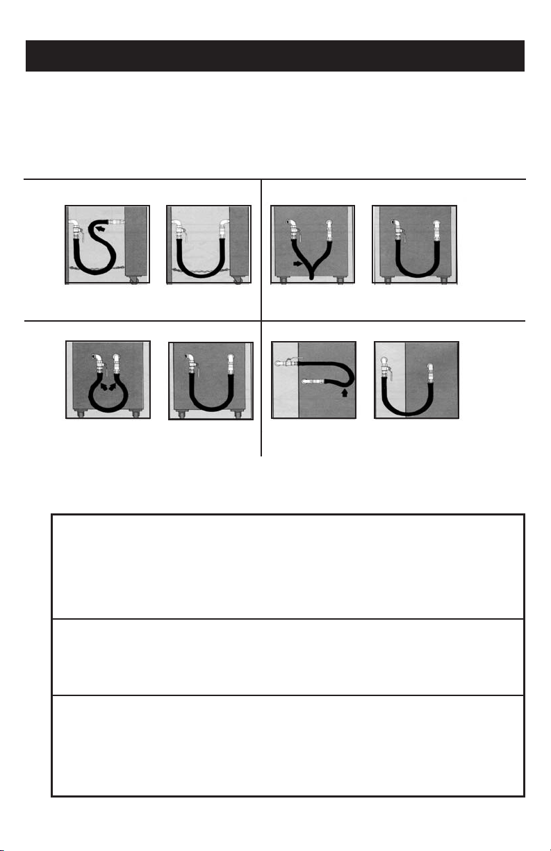
Installation Rights and Wrongs
WRONG
Avoid sharp bends and kinks when pulling equipment away from wall. Maximum
pull will kink ends, even if installed properly, and reduce connector life.
RIGHT
Minimum pull of equipment away from wall permissible for accessibility to
Safety QuikTMDisconnect.
WRONG RIGHT
WRONG RIGHT
99
SHARP BENDS: Install metal hose for vertical traverse with
a single, natural loop. Avoid sharp bends that strain and twist
the metal hose to a point of early failure at the coupling.
WRONG RIGHT
FATIGUE: Maintain the minimum or larger bending diam-
eter between the couplings creates double bends causing
work fatigue at the fittings.
Note: Appliance must be disconnected prior to maximum movement.
Minimum movement is acceptable to
leave connected.
Nominal connector ID inches
1/2” 150,000 106,000 86,600
3/4” 290,900 215,000 173,900
1” 581,800 442,700 347,800
1 1/4” 1,075,000 817,500 634,000
Nominal connector ID inches
1/2” 87,000 68,000 55,000
3/4” 232,000 180,000 139,000
1” 414,000 334,000 279,000
1 1/4” 699,000 541,000 419,000
Normal Connector ID inches
1/2'' 145,600 102,900 84,000
3/4'' 282,400 208,700 168,800
1'' 564,800 429,800 337,600
1- 1/4 1,043,600 793,600 615,500
NOTE: When using 0.2 water column pressure drop, capacity can be determined by multiplying the figures above by 0.632.
For capacities at conditions other than noted, contact your servicing gas supplier.
Note: Never insert such objects as
screwdrivers, probes, etc. into the
SnapFastTMvalve. The valve’s seat can
be damaged or forced off center.
Straight Length Capacity - BTU per Hr (w)
0.64 Sp Gr 1000 BTU per Cu. Ft. Gas at 0.5 in.
2ft. 4ft. 6ft.
CAPACITY WITH QUICK DISCONNECT DEVICE
2ft. 4ft. 6ft.
CAPACITY WITH MANUAL SHUT-OFF VALVE
2 ft. 4 ft. 6 ft.
TWISTING: Couplings and hose should be installed in the
same vertical plane. Failure to do so causes torsional twisting and
undue strain causing premature failure.
WRONG RIGHT
SELF-DRAINING: In all installations where “self-draining”
is not necessary, connect metal hose in a vertical loop. Do
not connect metal hose horizontally unless “self-draining” is
necessary, then use support on lower plane.
NOTE: Restraining Device is
mandatory for all types of
moveable gas appliances.
CONNECTOR CAPACITY
Water Column Pressure Drop
NOTE: Capacity was determined under test conditions specified by ANSI Z21.69
Page 19

10
USA
ANSI Z21.69/CSA 6.16
Metal Connectors for Moveable Gas
Appliances.
ANSI Z21.41/CSA 6.9
Quick Disconnect devices for use
with gas fuel.
ANSI Z21.15/CGA 9.1
Manually Operated Gas Valve for
Appliances,Appliance Connector
Valves and Hose End Valves.
CANADA
Certifications
CANADA
CR-92-009
Swivel Connectors for use with
Connectors for Moveable Gas
Appliances.
Approvals
USA
Design certified to ANSI/U.L. 567,
Pipe Connectors for Flammable and
Combustible Liquids and LP-Gas.
For use with natural gas and
propane.
USA
NSF International
Criteria C-2 special equipment.
(On PVC coated models only.)
CANADA
Approved by the Commonwealth of Massachusetts Board of State
Examiners of Plumbers & Gas Fitters. Connector length may not
exceed 36'' and lever handle valves are not permitted.
City of New York MEA# 274-02-E
Compliance
CANADA
CSA B149.1
Natural Gas and Propane Installation Code.
ANSI Z223.1/NFPA 54
Warranty
Warranties and Remedies
a. Warranty.Seller warrants to Buyer that it holds and will pass marketable title to
the commercial gas connectors sold hereunder. Seller further warrants to Buyer
that Seller’s commercial gas connector will be free from defects in material and
workmanship causing gas leakage during the life of the equipment to which the
commercial gas connector is originally connected or installed. (Limited lifetime
warranty).
Seller warrants to Buyer that the items and components manufactured by Seller
other than commercial gas connectors will be free from defects in material and
workmanship for a period of five (5) years from tender of delivery to Buyer. For
items not manufactured by Seller, the only warranty extended is that of the
manufacturer or suppliers, if any.
b. Exclusions and Conditions. Seller's obligations with respect to the express war-
ranties and remedies contained herein are conditioned on the following: (i)
Seller’s liability and Buyer’s exclusive remedy is expressly limited to Seller’s
replacement of the defective gas connector or other goods at Seller’s cost
(excluding labor and freight); it being understood such replacement will be
made only upon return of the defective item in accordance with Seller’s shipping
instructions and return authorization and subject to Seller’s
inspection; (ii) Buyer shall not assign its rights under these express warranties
and any attempted assignment shall render such warranties, but not any dis-
Conditions
Limitations of Liability.
The following limitations of Seller’s liability are acknowledged by the parties to
be fair and reasonable and shall apply to any act or omission hereunder, and to
any breach of this contract of which these terms and conditions form a part.
Disclaimer of Damages
In no event shall seller be liable for special, indirect, consequential or incidental damages, whether arising under contract, warranty, tort, negligence, strict
liability or any other theory of liability. Such damages include but are not limit-
ed to loss of profits, loss of use of the goods, damage to property, and claims of third
parties. Some states do not allow the exclusion or limitation of incidental or consequential damages, or any limitations on how long an implied warranty lasts, so
the above exclusion or limitation may not apply to you. This warranty gives you
USA
USA
– National Fuel Gas Code.
claimers or limitations, void and the goods shall be sold AS IS; and (iii) all commercial gas connectors and other goods shall be carefully inspected for damage
by Buyer upon receipt, be installed by individuals trained and certified as professionals with respect to such installation, and be installed, used, repaired and
maintained by Buyer in accordance with local codes or
regulations, standards set by American National Standard Institute and/or
American Gas Association Standards. The commercial gas connectors and
other goods shall be warranted in conjunction with the original installation only
and the express warranties and remedies contained herein shall not apply to,
and shall be void and of no further force or effect upon, damage and/or failure of
the commercial gas connectors and other goods caused by or
resulting from shipping; improper or unauthorized handling,
installation, alteration or repair; misuse, abuse or other occurrences or conditions
other than normal use thereof; application or conformity to local codes or regulations not previously made known to Seller; or accident or other casualty.
Disclaimer of Implied Warranties
Seller gives no warranties except those expressly contained herein.
Seller disclaims all other warranties implied by law, usage of the trade,
course of dealing or course of performance including, but not limited
to, the implied warranties of merchantability and fitness for a particular purpose.
specific legal rights, and you may also have other rights which vary from state to
state.
Notice and Time of Claim
(i) Buyer agrees to check and inspect all products against shipping papers and for
damage or shortage upon receipt of goods at destination; (ii) Every claim for loss,
damage in transit, or other cause visible upon inspection shall be made with carrier. Claims for shortage must be made within five (5) days of receipt; (iii) The
parties expressly waive the statute of limitations and agree that any legal proceeding for any breach of this contract shall be waived unless held within
two (2) years after the accrual of the cause of action therefor.
Page 20

9a. NOTA: Existen dos opciones para la orientación de los empalmes de desconexión rápida: OPCION #1 –
desconexión rápida en el aparato. OPCION #2 – desconexión rápida en el sistema de tubería.
10. OPCION #1: Desconexión Rápida fijada al lado del aparato (Vea la Figura 1).
Lado del Suministro de Gas:
A. Aplique un sellador de roscado (barniz para tubería) o cinta para roscado en las roscas localizadas en el
extremo del conector de gas.
B. Enrosque este extremo del conector de gas en la válvula de cierre y apriete con una llave.
Lado del Aparato:
C. Aplique sellador de roscado (barniz para tubería) o cinta para roscado en la salida macho del aparato (F) y
enrosque el codo de rosca macho y hembra (E) en la salida macho y apriete con una llave. Puede variar mucho
la ubicación tanto de la salida del equipo como de la T para el múltiple de la línea de suministro de gas.
D. Aplique un sellador de roscado (barniz para tubería) o cinta para roscado en las roscas macho del codo de rosca
macho y hembra (E).
E. Separe el extremo macho del acople de desconexión rápida o empalme (I) del extremo hembra o acople (H).
Enrosque el empalme macho (I) en el codo de rosca macho y hembra (E) y apriete. NOTA: El acople de
desconexión rápida DEBE ESTAR ORIENTADO de tal manera que el gas entre por la parte del conector y
salga por el empalme. El personal de instalación DEBE seguir las flechas de dirección del flujo que están mar-
cadas indeleblemente en el acople.
F. Aplique un sellador de roscado (barniz para tubería) o cinta para roscado en las roscas macho del conector de
gas. Enrosque el acople de desconexión rápida en las roscas del conector de gas. Apriete.
G. Conecte el acople hembra de desconexión rápida (H) en el empalme macho (I). (Figura 1 a).
H. Revise el apretado de todas las conexiones. Busque fugas de acuerdo a los procedimientos de prueba aceptados.
I. Después de la instalación del conector, empuje con cuidado el aparato de regreso a su posición normal de
operación. Verifique que el conector no esté acodado, muy doblado o atrapado bajo las ruedas del equipo.
11. OPCION #2: Desconexión Rápida fija en el lado de la línea de suministro de gas – "Desconexión
Rápida Invertida". (Vea la Figura 2 en la página siguiente).
ADVERTENCIA: Si decide seleccionar la Opción 2 de la instalación (desconexión rápida del lado del suministro de gas), la parte hembra del acople de desconexión rápida debe estar corriente arriba y fijo al suministro de
gas.
Lado del Suministro de Gas:
A. Aplique un sellador de roscado (barniz para tubería) o cinta para roscado en las roscas localizadas en el extremo
del conector de gas.
B. Enrosque el extremo del conector de gas en el empalme macho de desconexión rápida (K). Apriete con una
llave.
C. Separe el acople hembra de desconexión rápida (J) del empalme macho (K). (I). (Figura 2 a).
D. Aplique un sellador de roscado (barniz para tubería) o cinta para roscado en el empalme de la válvula.
E. Enrosque el acople hembra de desconexión rápida en la rosca del empalme de la válvula de cierre de gas. Apriete
con una llave.
Lado del Aparato:
F. Aplique sellador de roscado (barniz para tubería) o cinta para roscado en la salida del aparato (F) y enrosque el
codo en la salida. Apriete.
G. Aplique un sellador de roscado (barniz para tubería) o cinta para roscado en la rosca macho del codo de rosca
macho y hembra. Inserte las roscas macho en el acople de rosca hembra x hembra (no incluido).
H. Aplique un sellador de roscado (barniz para tubería) o cinta para roscado en las roscas del conector de gas.
Enrosque la manguera en el acople. Apriete con una llave.
I. Conecte el empalme macho de desconexión rápida (K) en el acople hembra (J).
J. Revise el apretado de todas las conexiones. Busque fugas de acuerdo a los procedimientos de prueba aceptados.
K. Después de la instalación del conector, empuje con cuidado el aparato de regreso a su posición normal de
operación. Verifique que el conector no esté acodado, muy doblado o atrapado bajo las ruedas del equipo.
3
Instrucciones de Operación
PARA CONECTAR: Empuje el empalme directamente en el acople hasta
que la manga caiga hacia delante en el anillo de retención. Abra la válvula de
cierre para abrir el gas.
PARA DESCONECTAR: Cierre la válvula para cerrar el gas. Retraiga la
manga y saque el empalme.
IMPORTANTE: EL ACOPLE NO SE DEBE USAR COMO EL CIERRE
PRINCIPAL.
Acople Manga Empalme
DIRECCION DEL FLUJO DE GAS
Page 21

2
INSTRUCCIONES DE INSTALACIÓN (FIGURA 1)
1. Antes de proceder, lea CUIDADOSAMENTE todas estas instruc-
ciones, incluyendo la sección de PRECAUCIONES Y ADVERTEN-
CIAS y también la sección ACIERTOS Y ERRORES EN LA
INSTALACIÓN de este folleto de instrucciones.
2. La válvula esférica manual de cierre (B), localizada en la línea del
múltiple (A), debe estar totalmente cerrada. Si no existe una válvula de
cierre en la línea del múltiple, debe cerrarse la válvula de la línea principal de suministro de gas (no se muestra). NO CONTINÚE A
MENOS QUE EL GAS ESTÉ CERRADO.
3. Saque el conector de gas y el contenido de la bolsa o caja.
4. Puede variar mucho la ubicación de los dos puntos de conexión para el conector de gas del aparato, la línea de suministro de gas y la salida del equipo. No es práctico mostrar todas las combinaciones posibles de la instalación. Estas
instrucciones incluyen varios ejemplos de las instalaciones más comunes. El instalador debe siempre tener mucho
cuidado de asegurarse que el conector no esté acodado, torcido o doblado cuando lo instale y que los accesorios de los
extremos del conector no estén sujetos a dobleces muy pronunciados. (Por favor vea los Aciertos y Errores en la
Instalación). Para las instalaciones que pueden resultar en un doblez muy pronunciado, se recomiendan los conectores
de gas SwivelMAX™ de Dormont.
5. Se recomienda que el múltiple del suministro principal de gas esté localizado de 76 a 107 cm del suelo.
Las T de la tubería deben apuntar hacia abajo.
6. Para facilitar el movimiento del equipo tan cerca de la pared como sea posible, los dos extremos del conector de gas
Dormont deben estar descentrados al lado de cada uno. (+/ – 7.6 cm se recomienda descentrar. Vea el Diagrama 1).
7. Cada componente del equipo DEBE tener su propia válvula manual de cierre aprobada. Antes de continuar, si no hay
una válvula manual de cierre accesible del gas para cada componente del equipo, asegúrese que el gas haya sido cerrado
en la válvula principal de cierre de cada componente del equipo.
8. INSTALACION DE LA VALVULA MANUAL DE CIERRE:
Extremos Hembra x Hembra de la válvula
a. Si la T de la tubería tiene rosca macho: Aplique un sellador de roscado (barniz para tubería) o cinta para roscado en
las roscas accesibles de la tubería localizadas en la línea de suministro del gas. Enrosque la válvula esférica de cierre
del gas en la tubería macho de hierro y apriete bien con una llave. Coloque la válvula esférica tan cerca del múltiple
como pueda, dejando espacio suficiente para abrirla y cerrarla. Coloque la válvula preferentemente en forma vertical. (vea la Figura 1).
b. Si la T de la tubería tiene rosca hembra: Aplique un sellador de roscado (barniz para tubería) o cinta para roscado
en las roscas del empalme de la tubería (no se suministra / la longitud preferida es de 7.5 cm). Enrosque el empalme
en la T hembra de la línea principal del gas. Luego enrosque la válvula de cierre en el empalme y apriete bien con
una llave.
9. ADVERTENCIA: El acople de Desconexión Rápida SnapFast
TM
(D) DEBE estar orientado de tal manera que el
gas entre por la parte hembra del conector (con válvula) y salga por la parte macho o empalme. SIGA las flechas de
dirección del flujo que están marcadas indeleblemente en el acople.
Diagrama 1 = descentrado
FIGURA 1
GAS
GAS
DIRECCION DEL FLUJO DE GAS
Figura 1 a
CC
OPCIÓN 1
Dispositivo de Desconexión Rápida
Instalado en el Aparato:
Este método de instalación, usado comúnmente en Norteamérica, muestra el
acople de desconexión rápida fijo en el lado del aparato. El empalme DEBE
estar siempre al lado del aparato, fijo a la salida del mismo o al regulador externo. Esto le permite al operador alejar el equipo de la pared en un conjunto de
equipo y a desconectar con seguridad el conector de gas de la parte posterior
del aparato.
II
HH
EE
Línea de Suministro de
AA
Gas (Múltiple de Gas)
Válvula Esférica de
BB
Cierre del Gas
Conector de gas Safety
CC
TM
System
Desconexión Rápida
DD
EE
TM
SnapFast
Codo de Rosca Macho y
Hembra a 90°
Salida Macho del
FF
Aparato
Dispositivo de
GG
Retención
Acople de Desconexión
HH
Rápida (hembra)
Empalme de
II
Desconexión Rápida
(macho)
Page 22

INSTALLATION FOR DUAL-FED FRONT MANIFOLD
EQUIPMENT LINE–UP
WHEN INSTALLING AN EQUIPMENT LINE-UP WITH DUAL-FED FRONT MANIFOLD GAS INLET:
Do not use a Safety QuikTM or SnapFastTM quick-disconnect coupling for this type of installation!
The use of a quick-disconnect coupling for this installation may be dangerous and is
not recommended.
WARNING!
Unless upstream gas shut-off valves on both inlet lines are completely closed, the uncoupling of one quick-disconnect will result in an open gas flow.
A Safety SystemTMflexible gas connector(s), without the quick-disconnect coupling may be used.
All installation instructions in this booklet describe installations that exclude the use of an external appliance gas regulator. If one is required, thread the regulator onto the appliance stub-out prior to installing the
street elbow. Afterwards, thread the female threads of the regulator and street elbow using a male-to-male
pipe nipple. Once complete, continue installation according to the remaining instructions.
Recommended Operating Instructions:
Cleaning Behind Equipment
I. Disconnecting the Gas Line
1) Turn off the equipment.
2) Carefully pull the equipment away from the wall, stopping when the restraining cable is taut.
3) Shut-off the gas supply by turning the lever on the gas ball valve (located off the main manifold line) to the “off ”
position. Unplug any electrical cords.
4) Disconnect the gas line by pulling back the sleeve of the quick-disconnect coupling. Be careful not
to drop the coupling on the floor, which may damage the unit.
5) Detach the snap-hook of the restraining cable.
6) Carefully pull the equipment away from the wall.
7) Clean behind the equipment, making sure no foreign substance, grease, cleaning solution or dirt
enter the quick-disconnect coupling or gas line.
II. Reconnecting the Gas Line
1) Reattach the quick-disconnect coupling by
inserting the plug (nipple) end into the coupling.
2) Reattach the restraining cable.
3) Reattach any electrical cords.
4) Turn the lever on the gas ball valve to the “on” position.
5) Carefully push the equipment back towards the wall, be sure that the gas connector is not twisted or kinked in a
severe angle. Check that the gas connector is not damaged or crushed by the equipment rolling over it.
6) If required, relight the pilot light. Turn the equipment on.
Dormont Engineering Support
11
The Dormont Engineering team is available to help with the design and layout of
foodservice equipment installations. We can design the proper gas connection to work with your equipment
and kitchen requirements.
Dormont has worked with consultants, national chains, and equipment manufacturers to solve tough gas
installations problems.
The previous CAD drawings are just a few examples of the kind of technical support we can provide. Contact
one of our Customer Service Specialists at 1-800-DORMONT (367-6668), for details.
Return Policy
No returns are to be made to Dormont Manufacturing Company without first obtaining a return authorization
number. Absolutely no returns will be accepted or credited without this prior approval. Returns will be subject
to a 25% restocking charge plus any transportation charges incurred.
Page 23

WARNING Canadian
The quick disconnect must be installed so that the gas enters the coupling half and exits the nipple half. You must follow the flow direction arrows
that are permanently marked on the coupler
1.The gas outlet must be in the same room as the gas-fired equipment and the connector must not be concealed within or run through any wall,
floor or partition.
2.All parts of the union supplied with the connector must be used, and no attempt shall be made to assemble union nuts directly to pipe
threads.
3.The connector must not be kinked, twisted or torqued.
4.Connectors are for use only on piping systems having fuel gas pressures not in excess of 1/2 psi (3.5 kPa).
5.For moveable appliance installation (e.g., appliances factory-equipped with casters), flexing and bending should be limited to the needs of pulling and
pushing the appliance in and out for cleaning, maintenance or installation. For fixed appliance installation, connector movement after installation should
be avoided.
6.Contact with foreign objects or substances must be avoided.
7.An accessible manual shutoff valve must be installed at the outlet of the gas supply piping system upstream of the connector.
8.The final assembly must be tested for leaks. Caution: Matches, candles, open flame or other sources of ignition shall not be used
for this purpose. Leak test solutions may cause corrosion—water rinse after test. To check gas supply piping system for leakage, see the National Fuel
Gas Code, ANSI Z223.1 or CAN/CGA-B149.1, Natural Gas Installation Code, and CAN/CGA-B149.2, Propane Installation Code.
9.The connector complies with the Standard for Connectors for Moveable Gas Appliances, ANSI Z21.69-CGA 6.16.
10. A restraining cable MUST BE connected at all time when appliance is in use.
Connector Capacity – Straight Length Capacity - BTU per Hr 0.64 SG.,
1000 BTU per Cu. Ft. Gas at 0.5 in. Water Column Pressure Drop
Nominal Connector
I.D. Inches 2ft. 4ft. 6ft.
1/2'' 150,000 106,000 86,600
3/4'' 290,900 215,000 173,900
1'' 581,800 442,700 347,800
1-1/4'' 1,075,500 817,500 634,000
Note: When using 0.2 water column pressure drop, capacity can be
determined by multiplying the figures above by 0.632. For capacities
at conditions other than noted, contact your servicing gas supplier.
Installation Instructions
Straight Length Capacity - BTU per Hr. 0.64 SG., 1000 BTU per Cu. Ft. Gas at
0.5 in. Water Column Pressure Drop
Nominal Connector
I.D. inches 2ft. 4ft. 6ft.
1/2'' 87,000 68,000 55,000
3/4'' 232,000 180,000 139,000
1'' 414,000 334,000 279,000
1-1/4'' 699,000 541,000 419,000
Note: Capacity was determined under test conditions specified
by ANSI Z21.69.
Avertissement : Instructions de montage au Canada
1.La sortie de gaz doit se trouver dans la même piéce que l’appareil á gaz et le connecteur ne doit pas être masqué par un mur, le sol ou une cloison, ni
traverser une de ces structures.
2.Utiliser toutes les piéces du connecteur union fournies avec le connecteur et ne pas essayer de monter les écrous du connecteur union
directement aux filetages au pas de gaz.
3.Ne pas couder, tordre ou serrer au couple le connecteur.
4.Les connecteurs ne doivent être utilisés qu’avec des tuyauteries dont la pression de gaz combustible ne dépasse pas 3.5 kPA (0,5 psi).
5.Pour l’installation d’un appareil mobile (par exemple les appareils équipés en usine avec des roulettes), le pliage et le cintrage doivent se limiter á tirer
et á pousser l’appareil lors du nettoyage, de l’entretien et du montage. Dans le cas d’un appareil fixe, éviter de déplacer le connecteur aprés le montage.
6.Éviter tout contact avec une substance ou un corps étranger.
7.Installer un robinet de fermeture manuelle accessible á la sortie de la tuyauterie d’alimentation de gaz, en amont du connecteur.
8.Des essais doivent être effectués pour vérifier que l’ensemble est étanche. ATTENTION: ne pas utiliser d’allumette, de bougie, de source
d’inflammation á flamme nue ou autre á cet effet. Les solutions pour essai d’étanchéité peuvent être á l’origine de corrosion - rincer á l’eau aprés
l’essai. Pour vérifier l’étanchéité de la tuyauterie d’alimentation de gaz, voir le National Fuel Gas Code [Code national de gaz combustible], ANSI Z223.1
ou CAN/CGA-B149.1, Natural Gas Installation Code [Code d’installation du gaz naturel], et CAN/CGA-B149.2, Propane Installation Code [Code
d’installation du propane].
9.Ce connecteur est conforme aux dispositions de la norme ANSI Z21.69 - CSA 6.16, intitulée Connectors for Movable Gas Appliances.
10. Un cable de retenue doit etre fixe en tout temps lorsqu’on utilise lʼappareil.
CAPACITÉ DU CONNECTEUR – Capacité d’une section droite - Btu/h
Gaz de densité de 0,64, 1000 Btu/pi cu., avec une chute de pression
de 0,5 po de colonne d’eau
Diam. int. nominal
du connecteur po 2 pi 4 pi 6 pi
1/2 po 150 000 106 000 86 600
3/4 po 290 900 215 000 173 900
1 po 581 800 442 700 347 800
1-1/4 po 1 075 500 817 500 634 000
6015 Enterprise Drive • Export, PA 15632 EE.UU.
(724) 733-4800 • FAX (724) 733-4808 • 1-800-DORMONT (367-6668) • www.dormont.com
CAPACITÉ AVEC DISPOSITIF DE BRANCHEMENT RAPIDE
Capacité d’une section droite - Btu/h (w)
Gaz de densité de 0,64, 1000 Btu/pi.cu.,
avec une chute de pression de 0,5 po de colonne d’eau
Diam. int. nominal
du connecteur po 2 pi 4 pi 6 pi
1/2 po 87 000 68 000 55 000
3/4 po 232 000 180 000 139 000
1 po 414 000 334 000 279 000
1-1/4 po 699 000 541 000 419 000
DM1016, Rev. 4, 8/10
Page 24

1
Instrucciones de Instalación del Conector de Gas para Equipo
Móvil con la Tecnología de Manguera Azul con StressGuard
ADVERTENCIA Por favor lea cuidadosamente el siguiente folleto de instrucciones. El no leer las instrucciones
por completo ni seguir las precauciones y advertencias puede provocar lesiones graves o la muerte.
PRECAUCIONES Y ADVERTENCIAS
1. La instalación DEBE cumplir con el Código Nacional de Gas Combustible (ANSI Z223.1) y con todos los códigos de
instalación local de gas.
2. La instalación y prueba DEBE ser efectuada por personal calificado. Asegúrese que el suministro de gas y que todas las perillas
de control del aparato estén cerrados antes de conectarlo al suministro de gas.
3. La salida del gas debe estar en el mismo cuarto que el aparato y el conector no debe estar oculto en, ni instalado a través de, una
pared, piso o división. Las conexiones flexibles de gas no deben hacer contacto con superficies de temperatura mayor de 110° C
(230° F), bordes filosos o cables.
4. El ensamblado final debe ser probado buscando fugas. PRECAUCION: No deben usarse llamas abiertas u otras fuentes de ignición para buscar fugas. Las soluciones para detección de fugas pueden provocar corrosión. ENJUAGUE CON AGUA
DESPUÉS DE LA PRUEBA. Para buscar fugas en el sistema de tubería de suministro de gas, vea el Código Nacional de Gas
Combustible Z223.1, NFPA 54 o CSA B149.1, Código de Instalación de Gas Natural y Gas Propano. Si detecta olor a gas,
cierre el gas del aparato y haga que un profesional certificado corrija el problema.
5. ADVERTENCIA: LAS SOLUCIONES DE LIMPIEZA O SUSTANCIAS QUÍMICAS FUERTES NO DEBEN
ENTRAR EN CONTACTO CON EL CONECTOR. Estas pueden incluir ácidos, solventes, purgantes con cloruro
de cinc u otros químicos clorados. En caso de contacto, enjuague el conector con agua y seque completamente.
6. Se debe instalar una válvula manual de cierre accesible en la salida del sistema de tubería del suministro de gas corriente arriba
del conector.
7. Se debe evitar el contacto con objetos extraños, cables o sustancias.
8. Evite el movimiento posterior a la instalación de aparatos fijos.
9. Debe limitarse el doblado o flexión de los conectores en los aparatos móviles (p. ej. los equipados con ruedas de fábrica) a sacar o
meter el aparato para limpieza o mantenimiento.
10. Los conectores deben usarse solamente en sistemas de tubería que tengan una presión del gas combustible que no sobrepase
(3.5 kPa) en los EE.UU. y 1 psi (7 kPa) en Australia. Las conexiones flexibles son adecuadas para usarse con gases de 1ª, 2ª y 3ª
familia solamente en sistemas de tubería que operan a presiones no mayores de 50 milibares.
11. NO LO REUTILICE EN OTRO APARATO O EN OTRO SITIO.
12. Además de la válvula principal de cierre del suministro de gas, DEBE instalarse una válvula manual de cierre de gas accesible y
aprobada, corriente arriba del conector de gas (a no más de 1.8 m (6 pies) del equipo al que da servicio). Cada componente del
equipo debe tener su propia válvula de cierre. NO USE el acople de desconexión rápida como el cierre principal del gas.
13. ADVERTENCIA: El acople de desconexión rápida DEBE INSTALARSE de tal manera que el gas entre por la
parte del conector y salga por el empalme. Debe seguir las flechas de dirección del flujo que están marcadas indeleblemente en el acople.
14. NUNCA INSERTE destornilladores, sondas, etc. en el acople de desconexión rápida. El asiento de la válvula puede dañarse o
descentrarse.
15. Al instalarse, el conector no debe estar acodado, torcido o doblado.
16. Asegúrese que todos los accesorios estén apretados apropiadamente. Cuando instale el conector de gas Safety System
recomienda usar dos llaves pericas de 35.5 cm (tamaño mínimo) como herramientas de instalación.
17. Se deben proveer los medios adecuados para limitar el movimiento de los aparatos con ruedas. Se REQUIERE un dispositivo
de retención en todos los tipos de aparatos móviles de gas. (ANSI Z223.1 y ANSI Z21.69).
18. El dispositivo de retención recomendado para los aparatos con ruedas es el Dispositivo de Retención de Dormont. Las instrucciones de instalación de este producto Dormont son parte de este folleto. Este "restrictor" deberá inspeccionarse como parte del
mantenimiento regular y de los procedimientos de seguridad. El cable de retención DEBE estar conectado siempre que se use el
aparato. Siga las instrucciones de la página 4.
19. Cuando instale un conjunto de equipo con entradas de gas del múltiple frontal de alimentación doble, NO use el acople de
desconexión rápida.
20. Para las instalaciones que requieren de mayor movilidad, se recomiendan los conectores de Gas SwivelMAX™ de Dormont.
21. El aparato DEBE estar desconectado antes de moverlo al máximo. Advertencia: NO ESTIRE DE MAS el conector de gas.
Cuando mueva el equipo (para limpieza, mantenimiento, etc.) siga las instrucciones de la página 8.
22. Este conector cumple con la norma ANSI Z21.69 / CSA 6.16 para aparatos móviles de gas.
TM
1
⁄2 psi
®
se
Dormont Manufacturing Company Export, PA 15632 EE.UU.
 Loading...