

Page 1
For Residential and Commercial Applications
ES-D-LVBlackCoated
Job Name ________________________________________
Job Location ______________________________________
Engineer _________________________________________
Approval ___________________________________
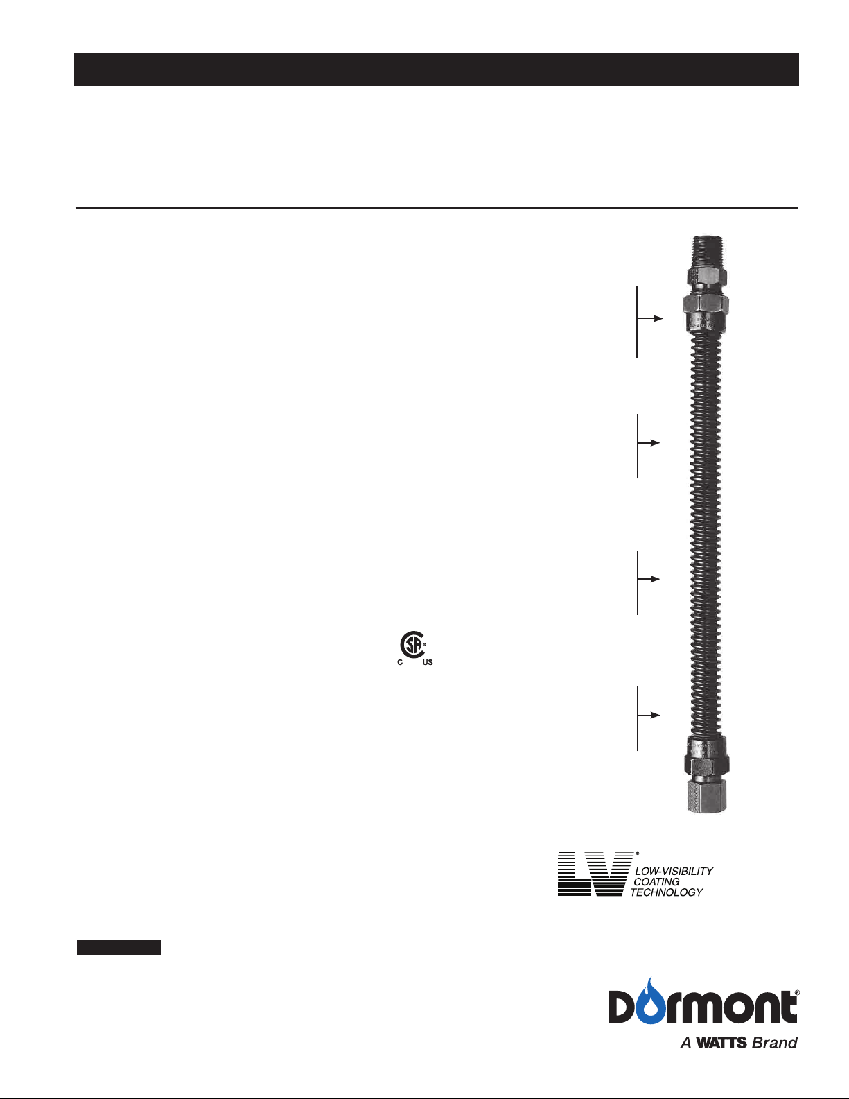
LV Black Coated
Gas Connectors
Specifically engineered for high-temperature applications such as gas
logs, fireplace inserts, and freestanding fireplaces
Features a low-visibility coating that hides the connector from view
Features and Specifications
• Tubing Annealed, 304 stainless steel (ASTM A240)
• Black coating. Maximum temperature rating: 350°F
• Flare Nuts: Steel with black plating
• Flare Adapters: Steel with Black Plating
• Approved for indoor/outdoor use with stationary
gas appliances/equipment.
• 100% factory leak tested
• When installing a new appliance or when an existing appliance is
moved to a new location a NEW gas connector must be used per
manufacturer's installation instructions and product standards.
• Designed for occasional movement after installation. Repeated
bending, flexing or extreme vibration must be avoided. Normal
operation of a clothes dryer, rooftop HVAC unit or SIMILAR
OUTDOOR APPLIANCE DOES NOT constitute extreme
vibration or movement.
Certifications and Approvals
• ANSI Z21.24/CSA 6.10 – Connectors for Gas Appliances
• ANSI Z21.75/CSA 6.27 – Connectors for Outdoor Appliances
and Manufactured Homes
• City of New York – MEA #376-92-M
• Approved by the Commonwealth of Massachusetts Board of State
Examiners of Plumbers and Gas Fitters – connector length may not
exceed 48"
Contractor ________________________________________
Approval _________________________________________
Contractor's P.O. No. _______________________________
Representative ____________________________________
SKU _____________________________________________
Black adapters and
flare nuts further
reduce visibility of
connector
Durable connector is
made of heavy-duty
304 stainless steel
Hi-temperature black
polymer coating
hides the connector
from view while withstanding up to 350° F
Exclusive No-Neck
Design: Increase
Tubing Flexibility
Applications
• Gas logs
• Fireplace inserts
• Free-standing fireplace
• Wall heaters
WARNING
All installations must completely comply with all Dormont manufacturing company warnings
and instructions, national, state and local codes and all applicable ansi standards.
Dormont product specifications in U.S. customary units and metric are approximate and are provided for reference only. For precise
measurements, please contact Dormont Technical Service. Dormont reserves the right to change or modify product design, construction,
specifications, or materials without prior notice and without incurring any obligation to make such changes and modifications on Dormont
products previously or subsequently sold. Refer to the owner's manual for warranty information.
10A and 20A Series
Page 2
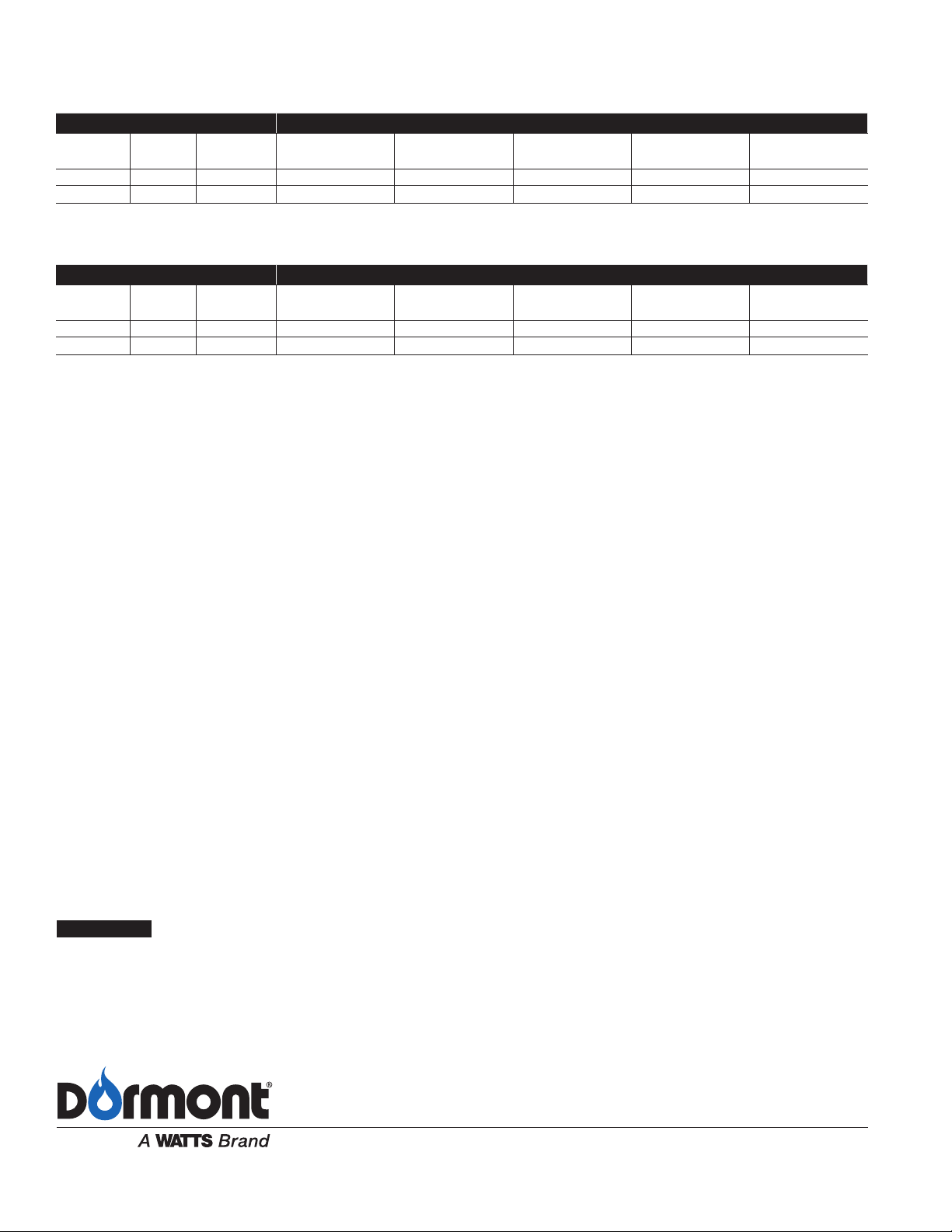
Minimum Flow Capacity
(Connector Minimum Flow Capacity – For Natural Gas (per ANSI Z21.24/CSA 6.10 & ANSI Z21.75/CSA 6.27)
Straight Length Capacity – BTU per Hr 0.64 SG., 1000 BTU per Cu. Ft. at 0.5 inch Water Column Pressure Drop)
Configuration ConnECtor LEngtH [inCHES]
SERIES
10A 3⁄8 1⁄4 48,000 43,800 40,000 36,400 33,400
20A 1⁄2 3⁄8 102,000 93,100 85,000 77,100 71,100
(Connector Minimum Flow Capacity – For LP Gas (per ANSI Z21.24/CSA 6.10 & ANSI Z21.75/CSA 6.27)
Straight Length Capacity – BTU per Hr 1.55 SG., 2500 BTU per Cu. Ft. at 0.5 inch Water Column Pressure Drop
SERIES
10A 3⁄8 1⁄4 76,800 76,080 64,000 58,240 53,440
20A 1⁄2 3⁄8 163,200 148,960 136,000 123,360 113,760
Nominal OD Nominal ID 12 18 24 30 36
in in
Configuration ConnECtor LEngtH [inCHES]
Nominal OD Nominal ID 12 18 24 30 36
in in
in in in in in
in in in in in
NOTICE
The minimum flow capacity values in the charts are at 0.5" w.c. pressure drop (inlet pressure
minus outlet pressure). If your gas system has more available pressure drop then a general
rule of thumb approximate calculation is as follows:
Minimum Flow Capacity @ your pressure drop = Square Root (your pressure drop/0.5) x value
from chart
Example: What is the approximate minimum flow capacity (natural gas) of the Dormont 10A
Series x 24" @ 1" wc pressure drop?
Answer: Square Root (1/0.5) x 40,000 = 56,568 BTU/hr
USA: Tel: (800) 367-6668 • Fax: (724) 733-4808 • Dormont.com
Canada: Tel: (905) 332-4090 • Fax: (905) 332-7068 • Dormont.ca
Latin America: Tel: (52) 81-1001-8600 • Fax: (52) 81-8000-7091 • Dormont.com
ES-D-LVBlackCoated 1610 © 2016 Dormont
 Loading...