

Page 1

insulating tubes
or
insulating tape
4135
( No.2, No.4)
RESET
TRIPPED
DORMAN
SMITH
LOADLINE YA2 & YA3 FRAME
Instruction Manual for
Moulded Case Circuit
Breakers
Safety Notices
Be sure to read these instructions and other documents accompanying this product.
Please familiarise yourself with handling of this product, safety information, and all
other precautions before mounting, using, servicing or inspection. In these
Instructions, safety notices are divided into "Warning" and "Caution" according to the
hazard level:
: A warning notice with this symbol indicates that neglecting the suggested
procedure or practice could result in lethal or serious personal injury.
: A caution notice with this symbol indicates that neglecting the suggested
procedure or practice could result in moderate or slight personal injury and/or property
damage.
Note that failing to observe notices could result in serious results in some cases.
Because safety notices contain important information, be sure to read and observe them.
Mounting Precautions
(For detailed mounting dimensions, refer to the TemBreak2 catalogue.)
Caution
Electrical work should only be undertaken by suitably qualified persons.
Do not place the product in an area that is subject to high temperature, high humidity,
excessive dusty air, corrosive gas, strong vibration and shock, or other unusual
conditions. Mounting in such areas could cause a fire or malfunction.
Be careful to prevent foreign objects (debris, concrete powder, iron powder, etc.) and
rainwater from entering product. These materials inside the product could cause a fire
or malfunction.
Prior to commencing any work on the product, open an upstream circuit breaker or isolator
to ensure that no voltage is applied to the product. Otherwise, electrical shock may result.
When connecting cable or busbar to the product, tighten terminal screws to the torque
specified in this manual. Otherwise, a fire could result.
For front-connected breakers, Insulate all bare conductors
of the line side until the breaker end. Insulate all bare
conductors by insulating tape or the like. Insufficient
insulation may result in short-circuit.
Do not block the arc gas vents of the product to ensure adequate arc space. Blocking
these vents could result in failure of circuit interruption.
Dorman Smith Switchgear Limited
8 Swinbourne Drive
Springwood Industrial Estate
Braintree Essex
CM7 2YG UK
Tel: +44 (0) 844 225 1063
2G0420SAA( KRB-5289)
Fax: +44 (0) 844 225 1064
Handling Precautions
Warning
Never touch terminals. Otherwise, electric shock may result.
Caution
When the breaker trips open automatically, remove the cause, then return the
handle to the ( ON) position. Should a fault be interrupted, the breaker must be
inspected. Otherwise, a fire may result.
Maintenance Precautions
Caution
Service and/or inspection of the product must be done by persons having expert
knowledge.
Before servicing or inspecting the product, open an upstream circuit breaker or the
like to isolate all sources of power. Otherwise, electric shock may result.
Regularly check that the MCCB terminal screws are tightened to torque values
shown within this manual, failure to do so may result in fire.
Other Precautions
Do not carry this product by accessory leads, as this may cause damage to the
product.
Unauthorised opening of the breaker cover will invalidate product warranty.
When installing the product, use wires or conductors, the cross sectional areas of
which accommodate the rated current of the product. Using wires or conductors with
inadequate cross sectional areas may cause false tripping and overheat.
Packaged Items/Assembly tools
Breaker : 1
Connections/Poles
Front
Connected
( FC)
1P
1P
Qty
2
2
Type
YA2,YA3
( M8 16)
( M4 65)
Operating Instructions
Handle
Single Clamp : 2
Double Clamp : 2
n
o
ti
Instruction Manual : 1
c
u
tr
s
In
ON
OFF
( ON) ( OFF)
( OFF) ( ON)
( ON) ( OFF)
( OFF) ( ON)
Type
YA2
YA3
Operation
effort
11N
19N
28N
22N
TRIP
TRIP
( OFF)
( OFF)
( RESET)
( RESET)
Type
Type
YA2
YA3
Operation
Operation
effort
effort
44N
44N
68N
68N
Page 2
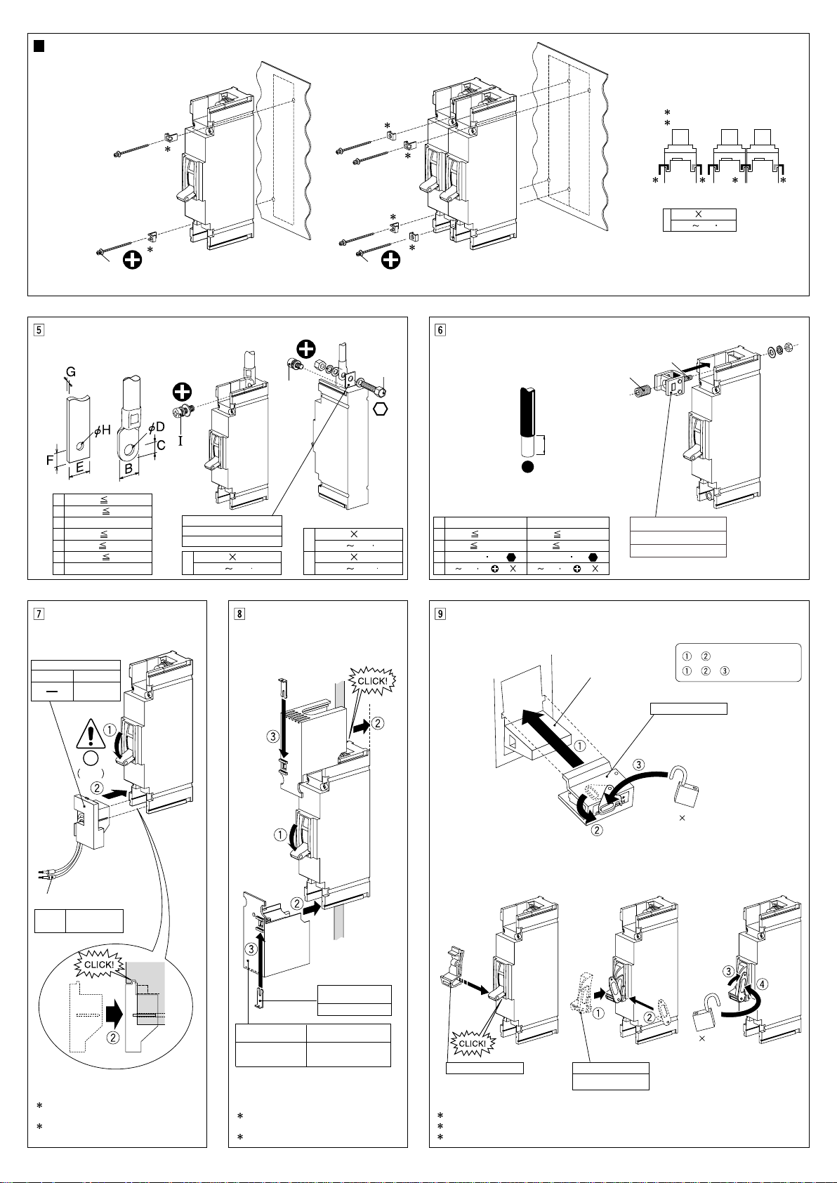
Breaker Mounting Procedure
1
2
2
1
1
1
1 1 12
A A
( No.2) ( No.2)
K
J
( No.4)
( No.4)
13
X
Z
4
5
Single or Isolate mounting Side by side multiple mounting
1 Single Clamp
2 Double Clamp
65mm
M4
2.2N m
1.7
Conductor Connection Procedure
B
C
D
E
F
G
H
(mm)
16
8
8.4
17
8.5
5
9
Rear Terminal Stud
YA2RT1P (125A)
YA3RT1P (250A)
I
4.9 6.9N m
Fitting Shunt Trip
Shunt Trip
YA2 YA3
YA31PST
J
8 16mm
K
Procedure for mounting
Terminal Cover
8
16mm
4.9 6.9N m
8 25mm
11.8 18.6N m
Procedure for mounting Pillar Terminal Cable Clamps,
Solderless Terminals
YA2 YA3
V
W
X
Z
17mm
50mm
6N m
2.4 3.4N m ( M5 15)
2
2.4 3.4N m ( M5 20)
20mm
70mm
10N m
2
Cable Clamps
YA2CC1P(125AF)
YA3CC1P(250AF)
Procedure for mounting Handle Holder/Lock
YA2
Handle Holder/Lock
Handle
+ : Handle Holder
+ + : Handle Lock
Handle Holder/Lock
OFF
Ring Mark
Shunt Trip
C1-C2
power source
After fitting, verify the function of the
Accessory.
When removing, remove the items in
reverse order of mounting.
Front connection
Connection
When removing, remove the items in
reverse order of mounting.
1 Unit: piece
Terminal Cover Lock
Terminal Cover
YA2TS1P (125AF)
YA3TS1P (250AF)
*
max 3 ( 5
YA3
Handle Holder Handle Lock
max 3 ( )
Handle Holder/Lock Handle Holder/Lock
YADL1
When removing, remove the items in reverse order of mounting.
)
5
 Loading...