


TT1100
Manual
04044239 - 08/2013
EN

© Copyright by
Kaba GmbH
Albertistraße 3
D-78056 Villingen-Schwenningen
Phone +49 7720/603-0
Fax +49 7720/603-102
www.kaba.com/workforce-management
All rights reserved. The document and its parts are copyrighted. Only Kaba GmbH has the right to commercialize,
market and distribute this document. This document, or any part of it, may not be copied or reproduced, adapted,
arranged, reworked or modified without the prior consent of Kaba GmbH.
All company, trademark or product names are trademarks or registered trademarks of their respective owners and are
protected.
Subject to technical changes without notice!
Order no. 04044239 - 08/2013

1
About this manual ............................................................................................................................ 5
2 Grouped safety messages................................................................................................................ 8
2.1 Use as directed.....................................................................................................................................................8
2.2 Mounting and Installation................................................................................................................................8
2.3 First-time operation............................................................................................................................................8
2.4 Service and Maintenance .................................................................................................................................8
2.5 Environmental protection................................................................................................................................8
2.6 Electrical dangers ................................................................................................................................................9
2.7 ESD (electrostatic discharge) protective measures..................................................................................9
3 Product description........................................................................................................................ 10
3.1 TT1100.................................................................................................................................................................. 10
3.2 Technical data....................................................................................................................................................11
3.2.1 System..................................................................................................................................................11
3.2.2 Interfaces.............................................................................................................................................11
3.2.3 Inputs/Outputs .................................................................................................................................11
3.2.4 Power supply.....................................................................................................................................12
3.2.5 Reader..................................................................................................................................................12
3.2.6 Environmental conditions............................................................................................................. 12
3.2.7 Weight..................................................................................................................................................13
3.2.8 Dimensions ........................................................................................................................................13
3.3 Conformity.......................................................................................................................................................... 14
3.4 Labeling............................................................................................................................................................... 15
4 Installation ......................................................................................................................................16
4.1 Installation conditions.................................................................................................................................... 16
4.1.1 General ................................................................................................................................................16
4.1.2 Installation site..................................................................................................................................16
4.2 Connections....................................................................................................................................................... 16
4.3 Mounting.............................................................................................................................................................17
5 Configuration..................................................................................................................................18
5.1 Web interface parameter description .......................................................................................................19
5.1.1 How to display the web interface............................................................................................... 19
5.1.2 Configuration parameters.............................................................................................................20
5.1.3 Application parameters ................................................................................................................. 59
5.2 Configuration file description...................................................................................................................... 63
5.3 Software update via USB stick......................................................................................................................63
6 Operation ........................................................................................................................................ 64
6.1 Fingerprint operation .....................................................................................................................................64
6.1.1 Enrollment.......................................................................................................................................... 64
6.1.2 Punching............................................................................................................................................. 66
7 Maintenance....................................................................................................................................67
7.1 Cleaning the housing...................................................................................................................................... 67
8 Packaging / returns.........................................................................................................................68
8.1 Complete devices............................................................................................................................................. 68

8.2 Electronic assemblies...................................................................................................................................... 68
8.3 Labeling............................................................................................................................................................... 69
9 Disposal........................................................................................................................................... 70
10 Index................................................................................................................................................ 71

Manual About this manual
1 About this manual
Validity This manual describes the Kaba TT1100 terminal as of
Serial number: 079800-000001
Manufacturing date: March 2013
Mainboard revision 1.5 or higher
Linux Version: Version 0.2.41 or higher
Addressees
This manual is written exclusively for specialists.
The descriptions in this manual are intended for personnel trained by the
manufacturer. The information in this manual cannot substitute the product
training.
The contents of this manual is intended for use by the following groups of people:
• Project manager
Project manager who is responsible for the system and entrusted with
project planning and realization.
• Fitter
Person specialized in mounting and installation.
Person who has an adequate technical training and sufficient experience and
who has been authorized by the manufacturer after completing the training
on the product.
• Service technician
Specialist for initial set-up and maintenance of the installation.
Person who has an adequate technical training and sufficient experience and
who has been authorized by the manufacturer after completing the training
on the product.
• Network administrator
Realizes the set-up of the device within the network and makes sure that the
devices are accessible within the network.
• Software partner
Specialists for connecting the system to the user software by defining
operating and booking sequences, programming the customer applications
and setting the parameters of the devices.
Important!
For reasons of device safety, some of the activities might only be carried out by the
SERVICE PERSON.
Only persons of the groups "Fitter" and "Service technician" have the status of a
SERVICE PERSON according to DIN EN 60950-1:2006.
TT1100 04044239 - 08/2013 5

About this manual Manual
Additional documentation
In addition to this document you will find a TT1100 OEM Manual, a TT1100 XML
Configuration manual, and a manual for terminals that also contain the TimeKey
Time and Attendance System.
The current product documentations can be found on the Internet in our Kaba
Portal at the following address: https://www.kaba.biz/de.
Customer no. (leave blank)
Username: docu2010en@kbs.kaba.com
Password: r+pj8c0v
Orientation in the manual
This manual contains the following orientation aids to facilitate finding of specific
topics:
• The table of contents at the beginning of the manual gives an overview of all
topics.
• The header always contains the respective main chapter.
• An index in the alphabetical order is given at the end of the manual.
Manual About this manual
Danger categories
Remarks with specifications or rules and restrictions to prevent injuries and property
damage are particularly marked.
Please read the danger warnings and user tips carefully. This information will help
prevent accidents and damage to your equipment.
Danger warnings are divided into the following categories.
DANGER
Describes an imminent danger that can lead to substantial bodily harm or to death.
WARNING
Describes a possibly dangerous situation that can lead to substantial bodily harm or
that can lead to death.
CAUTION
Describes a possibly dangerous situation that can lead to minor injuries.
NOTICE!
Important information for proper handling of the product.
Ignoring this information can cause device malfunction and the device or something
near it can get damaged.
Symbols
Depending on the source of danger, warnings are marked with symbols of the
following meaning.
General hazard warning
symbol
Hazardous voltage
Danger for electronic
Explosion hazard
Remarks
Please pay special attention to the remarks that are marked with symbols.
components due to
electrostatic discharge
Tips and useful information.
This information will help you to best use the product and its functionality.
TT1100 04044239 - 08/2013 7

Grouped safety messages Manual
2 Grouped safety messages
The device has been built in accordance with state-of-the-art standards and the
recognized safety rules. Nevertheless, its use may constitute a risk to persons and
cause damage to material property.
Read and observe the following safety instructions, before using the product.
2.1 Use as directed
The device or system is only intended for usage as described in chapter ”Product
description.”
Any use beyond the designated use is not according to rules. The manufacturer is not
responsible for damages resulting from improper use. The user/operator is
responsible for any risks associated with non-duly use.
2.2 Mounting and Installation
Mounting and installation may only be carried out by the SERVICE PERSON (see
chapter 1 / Addressees).
Installation may only be carried out in places that fulfill climatic and technical
conditions stated by the manufacturer.
Kaba GmbH is not liable for damages resulting from improper handling or incorrect
installation.
2.3 First-time operation
Check the device for visible damage during transportation or improper storage. Do
not commission a damaged device!
2.4 Service and Maintenance
Maintenance work / troubleshooting
Only the SERVICE PERSON (see chapter 1 / Addressees) is entitled to remove faults
and carry out the maintenance work.
Reconstruction and modification
Any reconstruction and modification of the device may only be realized by the
SERVICE PERSON (see chapter 1 / Addressees). All reconstructions and modifications
carried out by unauthorized personnel shall render void any liability.
2.5 Environmental protection
Please do not dispose of the device in your domestic waste.
Used devices contain valuable materials that should be recycled. Properly dispose of
used devices.

Manual Grouped safety messages
2.6 Electrical dangers
Mains voltage installations may only be carried out by a certified specialized
company or authorized electricians.
2.7 ESD (electrostatic discharge) protective measures
NOTICE!
Danger for electronic components due to electrostatic discharge.
Improper handling of printed circuit boards or components can cause damages that
lead to complete failures or sporadic errors.
• During installation and repair of the device, the ESD protective measures must
be considered.
The following rules must be considered:
• Wear an ESD wristband when handling electronic components.
Connect the end of the wristband to a discharge socket or an unvarnished
grounded metal component. This way, static charges are discharged from
your body securely and effectively.
• Touch only the edges of circuit boards. Do not touch the circuit board nor the
connector.
• Place all dismantled components on an antistatic surface or in an antistatic
container.
• Avoid contact between circuit boards and clothing. The wristband only
protects the printed circuit boards against electrostatic discharge from your
body, but there is still a risk of damage through electrostatic discharge from
your clothing.
• Transport and dispatch dismantled modules only in electrostatically shielded
protective bags.
TT1100 04044239 - 08/2013 9
Product description Manual
3 Product description
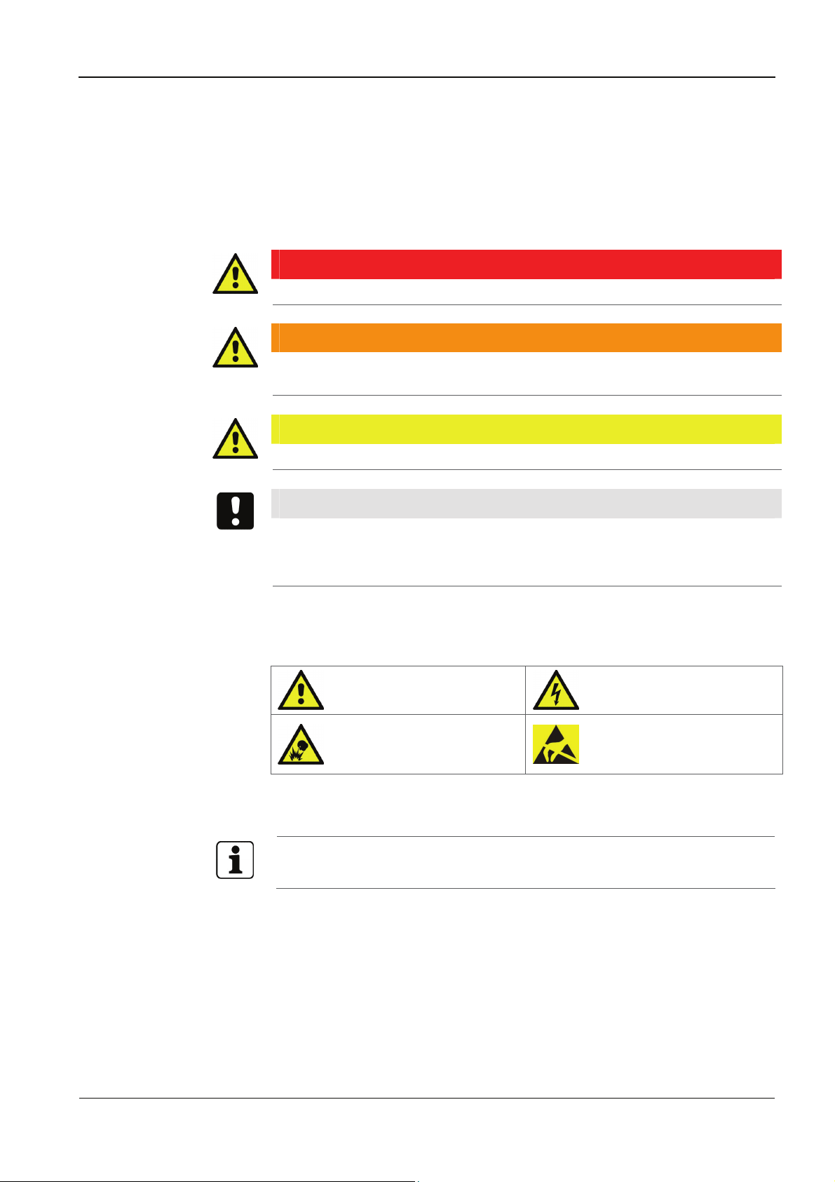
3.1 TT1100
The TT1100 is a time and attendance terminal with state-of-the-art technology.
The terminal software can be updated any time.
To display time data and information, the terminal has a graphic display with a
resolution of 320 x 240 pixels (QVGA).
The device has 24 capacitive key fields including a numeric keypad. Time data is
entered with a RFID reader or a biometric CBM reader (depending on the version). An
external reader (e.g. USB barcode scanner) can optionally be connected.
Communication is generally established via the Ethernet network
(10BASE-T/100BASE-TX).
Optionally, the terminal has 1 output (relay).

Manual Product description
3.2 Technical data
3.2.1 System
Gumstix overo board with an OMAP 3503 processor.
Memory
• 256 MB RAM / microSD up to 8 GB.
Graphic Display
• Resolution: 320 x 240 Pixel (QVGA), 24 colors.
3.2.2 Interfaces
3.2.3 Inputs/Outputs
• Background illumination.
Capacitive Keypad
• 24 keys for time and attendance and working data collection including
numeric keypad.
Ethernet
• IEEE802.3 compatible 10BASE-T/100BASE-TX Auto sensing (optional PoE, see
Power Supply).
USB
• USB 2.0 (down compatible to USB 1.1) supporting HID (human interface
device) USB devices.
The following interfaces are optional and possible as alternative!
RS-485 Host
1 Relay output (optional)
The relay output option is only available in combination with the RS-485 option.
• Potential-free contact
• Contact rating (max.): 1 A at 30 V AC / DC
The power source should meet applicable performance requirements for a limited
power source (LPS) according to EN 60950-1.
TT1100 04044239 - 08/2013 11

Product description Manual
3.2.4 Power supply
DC In
In the default configuration the device is supplied with a 24 W wall adapter:
• Input: 100–240 V AC / 50-60 Hz / 1 A max.
• Output: 12 V DC / 2 A
As an alternative a flush mount power supply can be used.
The power source should meet applicable performance requirements for a limited
power source (LPS) according to EN 60950-1.
PoE (Power over Ethernet)
Power supply of the terminal via the Ethernet cable,
according to IEEE 802.3af (max .12,95 W).
• Supported powering processes:
− Spare pair powering
over (Fast Ethernet free) wire pairs 4/5 and 7/8
3.2.5 Reader
The device supports the following reader types:
• RFID reader
• Reader for biometric identification
• USB connection for external reader (option)
3.2.6 Environmental conditions
• Relative humidity: 10% to 85%, non-condensing
− Phantom powering
over RX wires (1/2) and TX wires (3/6)
Power supply is superimposed to the data signal
− LEGIC prime/advant
− MIFARE Classic / DESfire
− HID Prox
− HID iCLASS
− Fingerprint reader
Memory sizes for 500, 3,000, or 5,000 people.
• Temperature range: 0–45 °C (32–113 Fahrenheit)

Manual Product description
3.2.7 Weight
Without biometric reader: 848 g
With biometric reader: 1000 g
3.2.8 Dimensions
Without biometric reader: 190 x 131.2 x 54 (mm)
With biometric reader: 240 x 131.2 x 95 (mm)
TT1100 04044239 - 08/2013 13

Product description Manual
Konf
3.3 Conformity
This device complies with the following standards:
EN 60950-1:2011
Devices with RFID reader Devices without RFID reader
EN 302291-1 V1.1.1 (2005-07)
EN 301489-1 V1.9.2 (2011-09) DIN EN 55022:2011
EN 301489-3 V1.5.1 (2012-07) DIN EN 55024:2011
according to the regulations of the EU Directives
2006/95/EG
1999/5/EG
2004/108/EG
Low voltage directive
R&TTE Directive
EMC Directive
NOTICE!
If an external barcode scanner is required, please observe the following:
EMC conformity is only guaranteed when using the Motorola LS2208.
This equipment complies with Part 15 of the FCC rules. Any changes or modifications
not expressly approved by the Manufacturer could void the user's authority to
operate the equipment. This device complies with Part 15 of the FCC rules subject to
the following two conditions:
1. This device may not cause harmful interference
2. This device must accept all interference received, including interference that
may cause undesired operation.
FCC Interference Statement for Class B EVM devices
This equipment has been tested and found to comply with the limits for a Class B
digital device, pursuant to part 15 of the FCC Rules. These limits are designed to
provide reasonable protection against harmful interference in a residential
installation. This equipment generates, uses and can radiate radio frequency energy
and, if not installed and used in accordance with the instructions, may cause harmful
interference to radio communications. However, there is no guarantee that
interference will not occur in a particular installation. If this equipment does cause
harmful interference to radio or television reception, which can be determined by
turning the equipment off and on, the user is encouraged to try to correct the
interference by one or more of the following measures:
• Reorient or relocate the receiving antenna.
• Increase the separation between the equipment and receiver.
• Connect the equipment into an outlet on a circuit different from that to which
the receiver is connected.
• Consult the dealer or an experienced radio/TV technician for help.

Manual Product description
Industry Canada (IC) Compliance Notice:
CAN ICES-3 (B)/NMB-3(B)
This device complies with Industry Canada license-exempt RSS standard(s).
Operation is subject to the following two conditions:
(1) This device may not cause interference, and
(2) This device must accept any interference, including interference that may cause
undesired operation of the device.
This device complies with Health Canada’s Safety Code 6 / IC RSS-210. The installer of
this device should ensure that RF radiation is not emitted in excess of the Health
Canada’s requirement.
Cet appareil est conforme avec Industrie Canada RSS standard exempts de licence (s).
Son utilisation est soumise à Les deux conditions suivantes:
(1) cet appareil ne peut pas provoquer d'interférences et
(2) cet appareil doit accepter Toute interférence, y compris les interférences qui
peuvent causer un mauvais fonctionnement du dispositif.
3.4 Labeling
Cet appareil est conforme avec Santé Canada Code de sécurité 6 / IC RSS-210. Le
programme d'installation de cet appareil doit s'assurer que les rayonnements RF
n'est pas émis au-delà de l'exigence de Santé Canada.
The identification plate is located on the bottom of the right hand side of the device.
Specified on the identification plate:
• Device name
• Product number
• Serial number
• Power data
• CE identification
• WEEE labeling acc. to DIN EN 50419
TT1100 04044239 - 08/2013 15
Installation Manual
1
Installation
4 Installation
4.1 Installation conditions
4.1.1 General
An accurate installation of all components is a basic requirement for a properly
4.1.2 Installation site
functioning device. The following installation instructions must be adhered to.
Clearances
4.2 Connections
Keep a distance of 20 cm on all sides between two devices with RFID readers.
Mounting height
The recommended mounting height is 140 cm to the top edge of the terminal.
Electromagnetic fields
The terminal must not be installed in the area of strong electromagnetic fields
caused by switching power supply, power lines, phase controllers, etc.!
Electromagnetic fields can affect the reading power or cause failures, in particular
with contactless readers (RFID).
Sun exposure
Direct sun exposure leads to reflections within the display area and a poor readability
of the display.
Please avoid installation at places with direct sunlight.
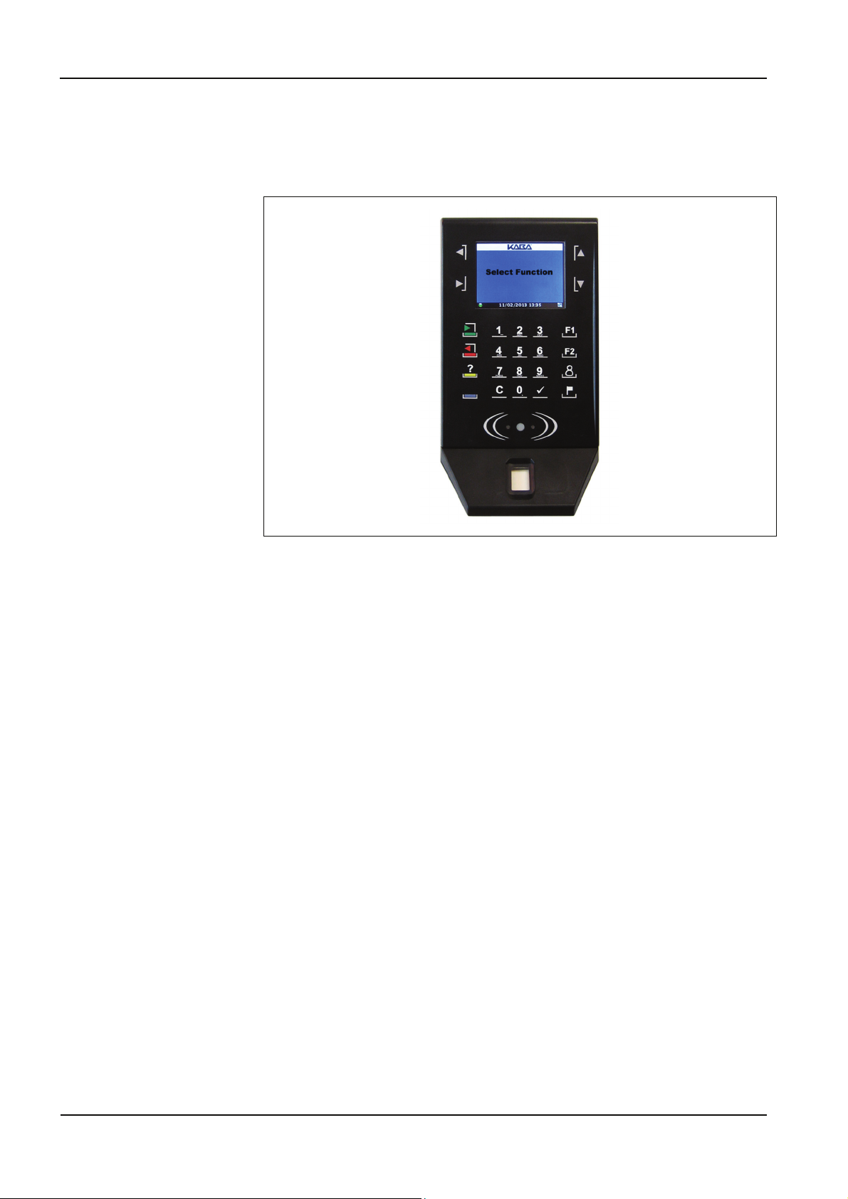
All connection cables for the terminal are plugged in at the bottom side of the
terminal.
5
4
32
1 Connector for the add-on module
2 RJ45 jack Ethernet 10/100 and PoE (optional)
3 Screw terminal for RS485 and Relay (optional)
4 DC Socket 6.5 mm for Power Supply 12 .. 24 V DC
5 Type-A USB 2.0 Host
Manual Installation
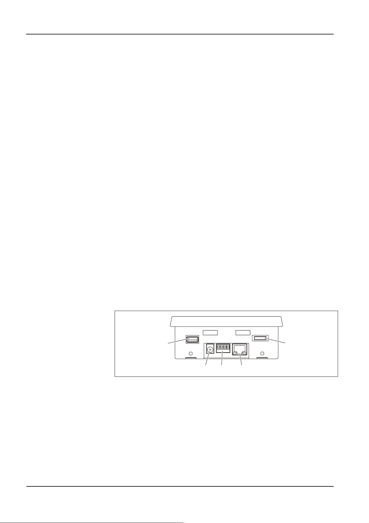
4.3 Mounting
Attach the wall mounting kit with four
countersunk screws to the wall.
For PoE devices just plug in the Ethernet cable.
Note that the device will be started
immediately if you have already connected the
other end into the switch.
For all other devices plug in the Ethernet and
the power cables.
Insert the terminal back plate slots into the wall
mounting kit top hooks and lower.
In case of a PoE the device will be started.
If you have a fingerprint device you now have
to assemble the fingerprint module.
You can not assamble the fingerprint module
prior to this step, because the screws are
attached to the bottom of the wall mounting
kit.
It is recommended to fix the right screw first.
TT1100 04044239 - 08/2013 17

Configuration Manual
5 Configuration
Although the terminal will be delivered preconfigured it might be necessary to
change some settings once it is installed.
In general you have to differentiate between two areas of settings:
• The so called framework settings: All settings associated with the network,
host, reader, date/time etc.
• The so called application settings: All settings associated with the display
content, the functions to be performed if a key is pressed, the sound and the
LED behaviour. These settings are defined in a configuration file, named
application.xml.
For changing the framework settings the terminal provides a wide parameter
collection in a so-called web interface.
The application settings can only be changed by editing the configuration file.
Manual Configuration
5.1 Web interface parameter description
5.1.1 How to display the web interface
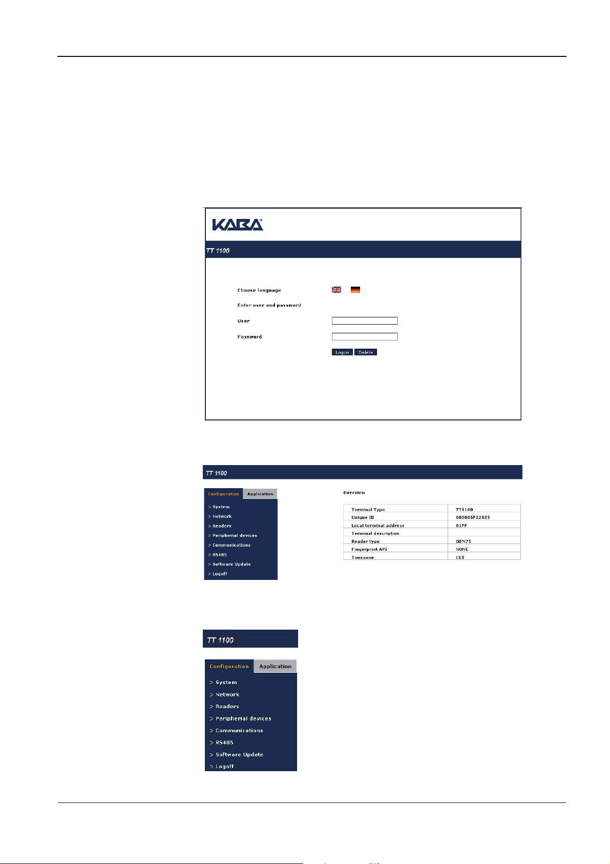
To connect to the web interface on an TT1100 terminal you must enter the terminal
URL in a standard web browser:
Example: http://terminal_ip_address where the “terminal ip address” is that of your
TT1100 terminal.
Login with the default user admin and password admin and click on Logon.
The Overview page is opened.
With a click on 1100 next to TLT in the upper left corner you can return to the
Overview page any time.
TT1100 04044239 - 08/2013 19
Configuration Manual
5.1.2 Configuration parameters
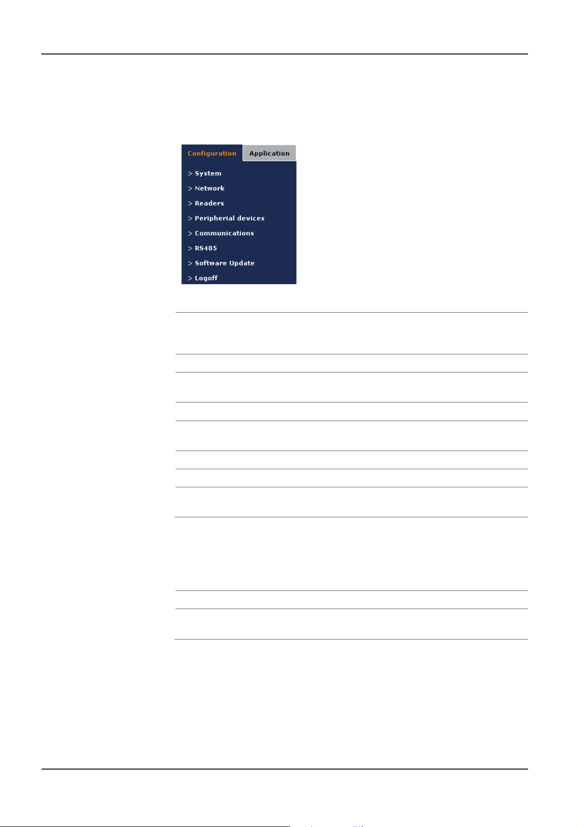
To open the configuration parameter group list, click on Configuration in the left
frame.
5.1.2.1 Configuration parameter groups – overview
System Terminal, Date/Time, Trace, Status, Java Statistics (for
developers), Users, Linux, Database Backup.
(See chapter
5.1.2.3)
Network TCP/IP, DHCP, Proxy, and FTP parameters (See chapter 5.1.2.4)
Readers Parameters for the available readers, barcode scanner and
Peripheral devices Display, Keyboard, LEDs and Sound. (See chapter 5.1.2.6)
Communications Parameters for the communication with the host system.
RS485 See chapter 5.1.2.8
Software Update See chapter 5.1.2.9
Logoff No matter what parameter page is opened in the right frame
5.1.2.2 Detailed parameter description
To display the individual parameter group pages click on the text link in the menu
bar in the upper part of the right frame.
On all the parameter pages you will find the buttons Save and Help.
Save This button will store your changes on the terminal.
Help This button will display basic help text displayed in the right
fingerprint reader. (See chapter
(See chapter
5.1.2.7)
5.1.2.5)
you can always log off by clicking on Logoff in the left frame.
column. The button text changes to Help off when selected.
Manual Configuration
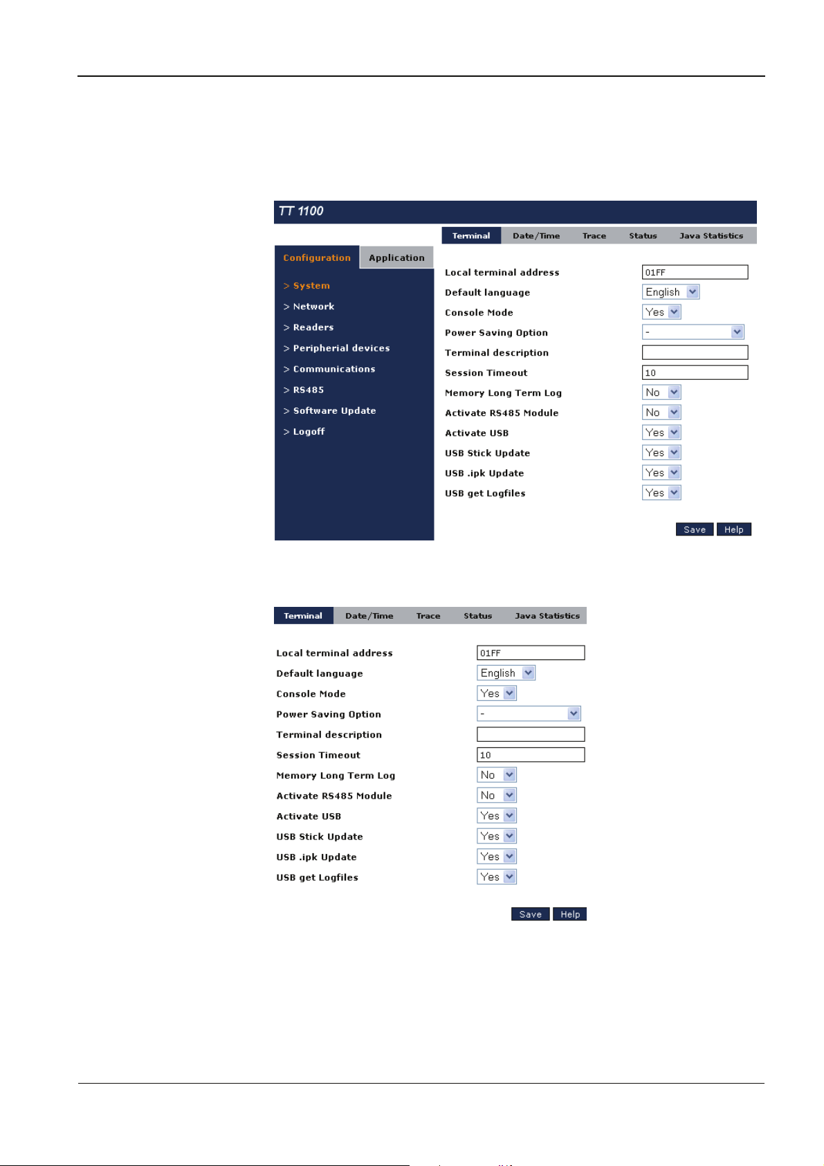
5.1.2.3 System configuration
To open the System configuration pages click on System in the Configuration menu
in the left frame.
Terminal parameters
The terminal parameter page is the default page in the system parameter group.
Local terminal address
The terminal address (logical ID) that is sent to the host system. (Default 01FF).
Default language
The preferred language for the web interface. English and German are available,
default English.
TT1100 04044239 - 08/2013 21

Configuration Manual
Console Mode
It is possible to activate or deactivate console at COM3, default YES, activated. The
Serial Port supports a Linux Console that can be useful for debugging. Please refer to
the chapter Serial Connection in the TT1100 OEM Manual.
Power Saving Option
Activate or deactivate a power saving option. Available options: Display Switch off: if
no motion is detected by the motion sensor, the display is turned off automatically.
As soon as a motion is detected it is turned on again. Default No.
Terminal description
Input field for a description for the terminal, e. g. the location.
Session Timeout
Timeout for a logged-in web interface user. Valid values from 10 to 99 minutes,
default 10.
Memory Long Term Log
If activated, memory resource information data is written into a log file for long term
monitoring. Default No.
Activate RS485 Module
If the optional RS485 module is installed, it has to be activated here. Default No.
Activate USB
The USB port can be completely deactivated by selecting NO. Default YES.
USB Stick Update
If this mode is active, updates can be performed via USB stick, e. g. a new
application.xml file, or a systemParameters.xml file to change parameters settings
(without opening the webinterface). Default YES.
USB .ipk Update
If this mode is active, whole update packages can be installed via USB stick. The
package must be provided as .ipk file. Default YES.
USB get Log files
If this mode is active, all log files on the terminal will be transfered onto the USB stick.
Default YES.
Manual Configuration
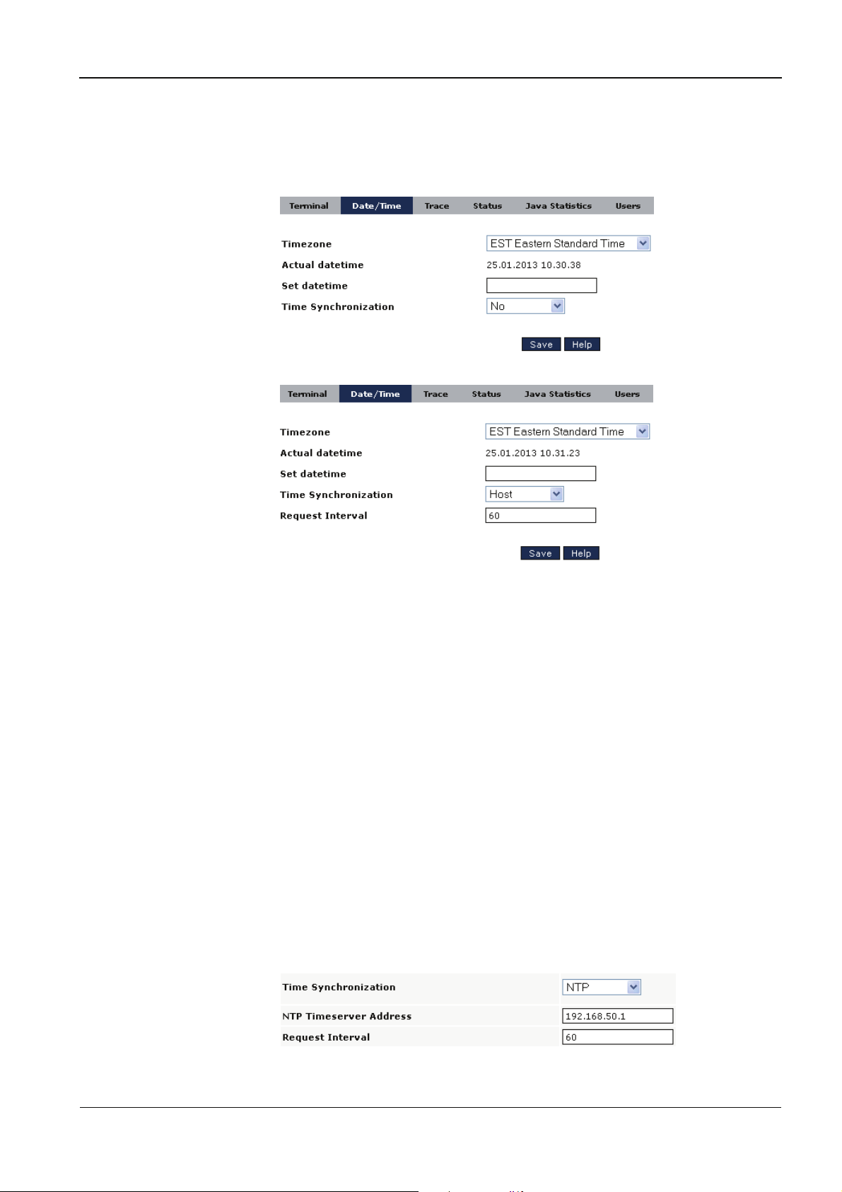
Date/Time parameters
To open the Date/Time parameter page click on Date/Time in the menu bar in the
upper part of the right frame.
or
Timezone
The time zone definition of the terminal. Available choices are the standard time
zones of America and Europe plus several explicit towns in America and Europe.
Actual datetime
Read-only field of the actual date and time of the terminal in the time zone defined
on the terminal.
Set datetime
Here you can set the new date and time for the terminal. Follow the syntax shown in
the Actual datetime field.
Time synchronization
Time synchronization mode. Choices are No, Host, NTP, NTP Server. (Default No.)
Host mode uses the data connection server. NTP mode uses an NTP Server for the
time synchronization, and NTP Server mode also provides an NTP Server for a subnet.
Request Interval
Interval of time requests in minutes, minimum 10 minutes, default 60.
If the time synchronization mode NTP is selected, an additional field is opened: NTP
Timeserver Address
TT1100 04044239 - 08/2013 23

Configuration Manual
NTP Timeserver Address
The TCP/IP address of the NTP server.
If the time synchronization mode NTP Server is selected, an additional field is
opened: NTP Timeserver Subnet
NTP Timeserver Subnet
In the NTP Server mode the terminal not only synchronizes its time with the NTP
Server specified in the field NTP Timeserver Address, but also works a an NTP Server
itself, providing Date/Time data to the subnet specified in this field.

Manual Configuration
Trace parameters To open the Trace parameter page click on Trace in the menu bar in the upper part
of the right frame.
Trace levels
For each component in the list different trace levels can be defined: Severe, Warning,
Info, Fine, Finer, and Finest.
The default is Warning. If you experience problems with a component you can set
the level to Fine. It is recommended to use the trace levels Finer and Finest only if
asked to by the support team.
Logging to a file
If this value is set to Yes, trace messages are written into a file named terminal.log
on the terminal. Default No.
There is a size monitoring active for the file terminal.log. If a limit of 5 MB is
reached, a second terminal log file is created. If the limit for this second log is
reached, the first log will be re-written.
Apart from a log that can be written into a file, the terminal provides an online log
with a limited size that can be read by opening the web interface page Application
-> Warnings.
The following parameters refer to this online log.
TT1100 04044239 - 08/2013 25

Configuration Manual
Logging to a file
If this value is set to Yes, trace messages are written into a file named terminal.log
on the terminal. Default No.
Internal Buffer Online Trace
The internal buffer holds the traces between 2 requests in memory. It can hold
between 50 and 1000 elements, default 100.
Online Trace Refresh Time
For the content of the Warnings page the automated refresh time in seconds
between 60 an 600, default 120.
Max Rows Online Trace Page
For the content of the Warnings page the maximum number of visible rows, default
1000.
Trace Selection for Online Log
For the content of the Warnings page the maximum trace level, default Warning.

Manual Configuration
Status page To display the Status page of the terminal click on Status in the menu bar in the
upper part of the right frame
For the different voltage values the following ranges are valid:
• CPU Supply Voltage: 3,3 V +/- 5% (3,135 V … 3,465 V)
• PoE Voltage: 12 V +/- 10% (10,8 V … 13,2 V) if in use. If not in use, ignore the
value even if it is higher than 0 V.
• Goldcap Voltage: 5 V +/- 5% (4,75 V … 5,25 V)
Power Supply Voltage (DC In): 12 V +/- 10% (10,8 V … 13,2 V) if the terminal is not
running with PoE. Otherwise ignore the value even if it is higher than 0 V.
TT1100 04044239 - 08/2013 27

Configuration Manual
General information
In the upper part of the page you will find general information about the terminal,
like Linux version, unique ID, power states, reader states and host connection state.
Condition based
Maintenance
Jar Files
The terminal provides Condition Based Maintenance Services, i. e. different
subsystem components are being monitored and if a state is reached where the
intervention of a service technician is required, this is shown in the Info column.
On the Status page you also find a summary of the software installed, with all the jar
files and their version numbers. This is useful information if you need support.

Manual Configuration
User parameters To open the Users parameter page click on Users in the menu bar in the upper part
of the right frame.
Apart from the default user admin with full access to the whole web interface you
can define other users with restricted access to certain pages and menus. For
example a network admin user who has only access to network-relevant pages.
TT1100 04044239 - 08/2013 29

Configuration Manual
If the new user Netadmin logs on with his password, he can only open certain pages:
Linux parameters To open the Users parameter page click on Linux in the menu bar in the upper part
of the right frame.
Restart/Shutdown
By selecting Shutdown linux, Reboot linux or Restart application, the operating
system or the application is restarted or stopped.
Actual root password + New root password
To change the password of the user ‘root’, enter the current root password (default:
root) and the new root password.
Actual admin password + New admin password
To change the password of the user ‘admin, enter the current admin password
(default: admin) and the new admin password.

Manual Configuration
Database Backup To open the Database Backup parameter page click on Database Backup in the
menu bar in the upper part of the right frame.
Make Initial Backup
By selecting YES a first backup of all web interface parameter settings is made.
Typically this is done after delivery when the terminal has been installed and set at
the customer site. An initial backup can only be performed once. It can be seen as
“factory setting”.
Make Backup
By selecting YES a backup of all current web interface parameter settings is made.
This kind of backup can be repeated any time. The previous backup will be
overwritten.
Recover Initial Database
By selecting YES the terminal will be set back to “factory setting”.
Recover Database
By selecting YES the terminal will be set back to the last backup of parameter
settings.
Automatic Backup
If set to YES backup will be performed each time a parameter setting is changed.
Date of Initial Backup, Last Backup, Last Restore
Read-only field of the backup / recover history.
TT1100 04044239 - 08/2013 31

Configuration Manual
5.1.2.4 Network parameters
To open the Network configuration page click on Network in the Configuration
menu in the left frame. The settings page appears.
Hostname
The host name of the terminal.
Domain
The name of the network domain to which the terminal belongs to.
TCP/IP address
The TCP/IP address of the terminal.
TCP/IP subnet mask
The TCP/IP subnet mask of the terminal (default is 255.255.255.0).
TCP/IP default Gateway
The TCP/IP address of the default gateway. With the value set to NO, the default
route to eth0 is used.
TCP/IP address of the name server
The TCP/IP address of the name server, if used.
Activate DHCP request
Allow or disallow the use of a DHCP Server for IP configuration. If this parameter is set
to Yes, the five parameters above are read-only.

Manual Configuration
The PIN for startup configuration
The PIN to be entered at terminal startup to change the IP configuration for the
terminal, default 1234. Leave blank to disable the start-up dialog.
Activate Network Interface
The network interface to be used, currently RJ45 only.
Mac Address
Read-only field showing the MAC address.
Proxy Server
The IP address or name of the Proxy Server.
Proxy Port
The port number of the Proxy Server.
Socks Proxy Server
(For Webservice) The IP address or name of the Socks Proxy Server.
Socks Proxy Port
(For Webservice) The port number of the Socks Proxy Server.
Network config
By selecting Activate, the network configuration of the operating system is
activated. This is required after changing a network parameter.
Enable System FTP Server
By default no FTP Server is running on the terminal. If it is necessary for a host system
to connect to the terminal via FTP, set this parameter to YES.
TT1100 04044239 - 08/2013 33

Configuration Manual
5.1.2.5 Readers
To open the Reader configuration pages click on Readers in the Configuration menu
in the left frame.
Badge reader
The Badge reader parameter page is the default page in the reader’s parameter
group.
Reader type
Type of badge reader installed in the terminal. Choices for the reader type:
The reader type is set to the correct reader type at delivery. If the customer badge
type is known at the time of production also all other reader parameters are set
accordingly.
In the following only the main parameters are explained. If you need help with
special badge reader settings, please contact our support. Prior to that you might
find the help texts useful.

Manual Configuration
Reader type HID_MCM
Badge Technology The only valid badge technology here is PROX.
Default lengths and offsets For the common badge format predefined
settings for badge and company code lengths
and offset can be used by selecting YES for this
parameter. If these parameters are to be
customized first choose NO and save, so that the
length and offset parameters are set visible.
Badge format Possible badge formats:
Check data parity Should the terminal perform a parity check on the
data received from the reader?
TT1100 04044239 - 08/2013 35

Configuration Manual
Reader type OEM75
For ICLASS badges:
Reader firmware The OEM75 module has ist own firmware.
CREO2RDR1B05-01.00 is a firmware version that
supports both badge technologies, iCLASS and
MIFARE.
Badge Technology For the reader type OEM75 the badge
technologies iCLASS and MIFARE are valid
selections.
Badge type (not relevant)
Badge format The card data format. Possible badge formats:
26-bit, 35-bit (Corporate 1000) and 37-bit are the
established formats. If the user has a different
card format he has to provide the coding details.
Mode
Usually the HID application area contains the
relevant data. Unique card serial number can be
chosen to read only the unique ID of the badge.
This might also be a MIFARE badge. If the user has
a different card format and needs a different
mode, he has to provide the coding details.

Manual Configuration
Reader type OEM75
For MIFARE badges:
Further parameters
For all the other reader parameters please refer to the Help, i. e. press the button
Help.
Reader type SM4200
Badge format Possible badge formats:
TT1100 04044239 - 08/2013 37

Configuration Manual
For badge format
Variable
Badge writer
Further parameters
For all the other reader parameters please refer to the Help, i. e. press the button
Help.
Currently writing data on a badge is not implemented.

Manual Configuration
Badge interpreter To open the Badge interpreter page click on Badge interpreter in the menu bar in
the upper part of the right frame.
For Legic
For HID Prox
For iCLASS
For MIFARE
TT1100 04044239 - 08/2013 39

Configuration Manual
Reader setup To open the Reader setup page click on Reader setup in the menu bar in the upper
part of the right frame.
Please select option
For an OEM 75 iCLASS reader select OEM75 Key Management, if you want to load
and store a key for accessing a particular area of the badge data.
For an Legic reader SM4200 select SM4200 Launching Procedure if you want to
launch the reader module with special stamp data,
Once you selected an option you are guided through the process.

Manual Configuration
Fingerprint To open the Fingerprint parameter page click on Fingerprint in the menu bar in the
upper part of the right frame.
Fingerprint API
The only possible Fingerprint API at the moment is SagemUSB, i. e. connecting a
Sagem fingerprint module via (internal) USB. Note: This module will work even if USB
in general is turned off (Parameter Activate USB with value NO).
Delete all Templates
With this parameter you can delete all existing templates in the Sagem internal
database.
Size of Sagem database
The current size of the internal database on the Sagem module. Available sizes for
ordering: 500, 3000, and 5000.
Free rows in Sagem database
Shows the number of free datasets in the Sagem internal database.
Process async messages
If this parameter is set to NO, the dialog messages from the Sagem module such as
“Press harder”, “Finger up” etc. are suppressed. The default is Yes.
Process matching score messages
If you need the matching score for the finger as a return value for your application,
you can set this parameter to Yes. The default is No.
SW Version
The fingerprint module has its own firmware, which is shown in this field.
Unique Reader ID
Each fingerprint module has its own unique ID, which is shown in this field.
TT1100 04044239 - 08/2013 41

Configuration Manual
Fingerprint distribution To open the Fingerprint distribution parameter page click on Fingerprint
distribution in the menu bar in the upper part of the right frame.
Fingerprint configuration
If the user templates should be collected on one terminal only and should be
distributed from there to other terminals, select here if the terminal is to be used for
enrollment – Master – or for receiving the templates – Slave.
If configured as Master:
Slave 01 to 10
The TCP/IP address of the slave terminal(s).
Templates file
Before starting the transfer, the archive file with the templates has to be created.
Therefore click on Archive. The text changes from NOT CREATED to CREATING and if
finished to CREATED.
User name
The name of the user to be used for the transfer of the template file to the slave
terminal, typically the user admin
Password
The password of the user to be used fort he transfer of the template file to the slave
terminal.

Manual Configuration
If configured as Slave:
Last download
Read-only field that shows the date and time of the last successful download (or „Not
downloaded“, if so far no archive file was downloaded).
Templates folder
Folder for unpacking the archive file for later loading the templates into the
fingerprint module. Do not change this value.
Barcode Scanner To open the Barcode scanner parameter page click on Barcode scanner in the
menu bar in the upper part of the right frame.
Serial Reader
The only choice for a barcode scanner type is Default USB.
If you define this scanner type the event interface is automatically set to hiddev0. It is
recommended not to change this setting.
It is important that the barcode scanner in configured to IBM Hand-Held USB
Currently no serial reader type is implemented.
TT1100 04044239 - 08/2013 43

Configuration Manual
5.1.2.6 Peripheral devices
To open the configuration pages for peripheral devices click on Peripheral devices
in the Configuration menu in the left frame.
Display
The Display parameter page is the default page in the parameter group for
peripheral devices.
Display type
So fare the only available display type is TFT35
Display Brightness
You can change the brightness of the display where 127 is the maximum value.

Manual Configuration
LED To open the LED parameter page click on LED in the menu bar in the upper part of
the right frame.
LED Brightness
You can change the brightness of the two LEDs where 127 is the maximum value.
LED Test
You can test the LEDs e. g. after changing the brightness. Choose a color in the list –
the value All results in white LEDs – and click on Save.
The LEDs will be turned on for 3 seconds in the selected color.
Apart from the general brightness parameter in the web interface here, the LED
brightness can be varied each time the LEDs are called in the configuration
application xml file. So you can e. g. accompany a user warning with much brighter
LEDs than a punch confirmation.
TT1100 04044239 - 08/2013 45

Configuration Manual
Keyboard parameters To open the Keyboard parameter page click on Keyboard in the menu bar in the
upper part of the right frame.
Keyboard Type
The only available choice is the keyboard type TT1100.
The use of this page is that a user can deactivate keys that are not in use and / or not
even printed on the front cover. For example the user can deactivate the numeric
keypad by clicking with the left mouse button on the corresponding keys and then
save. The result looks like this:

Manual Configuration
Sound
To open the Sound parameter page click on Sound in the menu bar in the upper
part of the right frame.
With these parameters you can change the volume of the terminal speaker. Note that
the maximum volume is equivalent to 87 dB.
Volume Gain
Changes the gain value (amplification factor) of the volume, valid values 0 – 2.
Volume Coarse
Changes the coarse adjustment of the volume, valid values 0 – 17.
Volume Fine
Changes the fine adjustment of the volume, valid values 0 – 63.
Volume Test
To test the volume changes, select Volume Test On and Save. A sample sound file is
played.
TT1100 04044239 - 08/2013 47

Configuration Manual
5.1.2.7 Communications parameters
To open the Communications configuration pages click on Communications in the
Configuration menu in the left frame. With the Communications parameters you
configure your host connection.
Upload
The Upload parameter page is the only page in the Communications parameter
group. It describes the communication from the terminal to the host.
Connection type
The protocol to be used for sending messages to the host. Choices are TCP-Client,
TCP-Server, Web Service, and FTP. (A TCP-Server is waiting for a connection
request and a TCP-Client is trying to open the connection.) Default TCP-Client.
TCP/IP address
The TCP/IP address used for the host data connection.
TCP/IP port
The TCP/IP port used for the host data connection, default 1089.

Manual Configuration
Message format
Defines the format in which the messages are to be sent to the host. Default XML.
Time-out for host reaction [ms]
Time-out interval for a confirmation message from the host (ms). Default 10000.
Server alive check
The interval in seconds between the server alive checks, default 180. If during this
interval no alive check exchange happens, the terminal is offline.
Use time intervals for upload?
Currently only for the connection type FTP. If this option is set to Yes, the connection
to the FTP server will be established every n minutes, where n is the connection
interval you specify in the next field. Default No.
Upload connection interval
The time interval in minutes you want the connection to the FTP server to be
established. Choose an interval not less than 10.
Use time slots for upload?
By using online time slots you can restrict the permanent host connection to the
specified periods of time. If you set this parameter to Yes you have to at least define
one start-end-pair, during which the connection to the host is to be established. You
can define up to 10 time slots. Default No.
…
Interval n Start [HH:MI]
The time to go online in the format hh:mi.
Interval n End [HH:MI]
The time to go offline in the format hh:mi. If lower than the start time, the next day is
assumed. Note that for the connection type FTP only the start time applies.
TT1100 04044239 - 08/2013 49

Configuration Manual
After choosing and saving the Connection Type option FTP, the following
parameters are added to the page:
FTP host IP address
The IP address of the FTP server.
FTP user name
The name of the authorized user on the FTP server. Default admin.
FTP password
The password for the FTP user. Default admin.
FTP directory
The directory on the FTP server to which the file transfer should take place. If this
parameter is left empty, the connection will be established to the default directory
set up for the user.
FTP file name
The name of the FTP file. Default bookings.dat.
Change file name
The rule for changing the file name on the FTP server. Either no change or change by
adding a timestamp to the file name. Default No.
FTP send timeout
The waiting time in case the previous version of the specified file has not been
removed from the server. During this time the file will be resent. Default 120000
(ms).
Use SFTP
If you set this parameter to Yes, all transfers are executed with Secure FTP. Default
No.

Manual Configuration
In order to activate the FTP connection either the parameter Use time intervals?
or Use time slots? has to be set to Yes. When using time slots only the start time is
considered, not the end time.
After choosing and saving the Connection Type option Web Service, the page
content changes to the following:
Special web service parameters:
Use HTTPS?
If this mode is active, a secure communication is used. The terminal first has to
request a certificate from the web server though. Default No.
Server Address
The IP address or the hostname of the server.
Server Port
The port of the server to connect to. Default 8080 for http.
User
The authenticated user for the web service.
Password
The password of the web service user.
TT1100 04044239 - 08/2013 51

Configuration Manual
Web Service Implementation
The class name of the web service implementation, default
com.edata.connection.webservice.WSServerConnectionTL
(For USA more often used: …WSServerConnectionTLUS)
Endpoint address for Transactions
The servlet (complete path) for receiving the transactions.
Endpoint address for Device Manager
The servlet (complete path) for processing other device messages such as the heart
beat.
Id to use for requests
The ID used for server requests. This can be either the logical ID (the field Local
terminal address on the terminal parameter page) or the name (the field Hostname
on the network parameter page, by default the MAC address).
Heartbeat Interval [min]
The interval between heart beat messages in minutes, minimum 5 minutes, default
10 minutes.
Heartbeat Reconnect Interval [s]
For the offline case: the interval between reconnection tries in seconds, minimum 10
seconds, default 60 seconds.
Startup Connect Interval [s]
For the offline case at startup: the interval between reconnection tries in seconds,
minimum 10 seconds, default 30 seconds.
It is recommended to set the parameter Timeout for host reaction to 45 seconds
(value 45000).
Also it is recommended to set the parameter Server alive check to 0, because the
alive check with Web service is done by heartbeats.

Manual Configuration
5.1.2.8 RS-485 parameters
RS-485 Configuration
To open the RS-485 parameter pages click on RS485 in the Configuration menu in
the left frame. With the RS-485 parameters you configure the optional RS-485
module.
Start RS485 Devices
This parameter defines if the RS-485 Manager is to be started or not.
The RS-485 Manager can only be started if the parameter Activate RS485 module
on the Terminal parameter page is set to YES.
The terminal examines whether the RS-485 module hardware is in fact installed. It
only makes sense to configure the RS-485 device, if the read-only parameter at the
bottom of the page shows Installed.
TT1100 04044239 - 08/2013 53

Configuration Manual
Available Channels
This is an information list of USB Serial Converters recognized by the USB-Serial
driver.
Typically the TT1100 RS485 module resides on channel ttyUSB12
Reader Communication Config
The baud rate configuration for the serial communication protocol. Default 9600.
Reader Protocol
The reader communication protocol. Fix value HADP (HID HADP Protocol).
Badge Configuration
The length of the company code and badge number.
Specify the values coma separated.
If you need a company code length of 5 and a badge length of 10, then set this value
to 5,10.
HID iCLASS cards are recognized automatically, Supported are iCLASS 26 Bit H10301
or 37 Bit Cards H10304.
Note that the records stored in the booking storage files contain the badge
number with a certain length definition. Make sure that the length defined here is
the same or longer than defined for a record (in the application.xml file in the
storage section).
Config Group
You can configure the connected readers, e. g. one reader collects IN punches and
the other one OUT punches. To differentiate the two types you can use configuration
groups.
For each group the following values can be configured:
− LED color when online: RED, GREEN, AMBER
− Transaction type when valid OK
− Transaction type when invalid
To which group a reader belongs is defined in the validation group.xml file (in the
syntax format <data trmid="1201" group="OUT" /> where trmid is the channel and
reader ID).
Blink Config Group
For each of the 3 groups you can configure a separate LED blink behavior. The field
value consists of 10 comma-separated parts, the first 5 for valid transactions, the
second 5 for invalid transactions, each in the format Time, TimeOn, TimeOFF,
ColorON, ColorOFF
− Time: total blink time in 1/10 seconds, maximum 49
− TimeOn: time for LED on
− TimeOff: time for LED off
− ColorON: Color LED on
− ColorOff: Color LED off
Example: 10,5,5,GREEN,OFF,25,1,1,RED,OFF

Manual Configuration
Buzzer Configuration
Configure the buzzer (the acoustic signal) for valid and invalid transactions. The field
value consists of 6 comma-separated parts, the first 3 for valid transactions the
second 3 for invalid transactions, each in the format Retries,TimeOn (1/10 sec),
TimeOFF(1/10 sec).
Example: 1,3,1,3,1,1 means 1 buzzer retry for 300ms on and 100ms off for valid
punches, 3 buzzer retries for 100ms on and 100ms off.
Buzzer Exclude List
Reader list for a special buzzer configuration. The field value consists of the channel
ID with reader ID for the designated reader(s), like 00000101 for channel 0 reader 0
and channel 1 reader 1.
Buzzer Configuration Exclude List
Buzzer configuration for the reader(s) in the exclude list.
For the field value see Buzzer Configuration above.
USB Hub
Default Internal. The internal Hub supports one channel and two Readers on that
channel.
Event Mode
The Reader Events can be worked from a native Library Functionality. This is
necessary if you have a lot of readers because of performance issues.
If you have at most 2 readers connected the Reader Events can be worked by the
application.xml procedure.
Event Mechanism
The Library Mode supports two mechanisms:
Asynchronous work of Reader events and Synchronous work of reader Events.
The asynchronous mode is to support best performance. Recommended is
Synchronous mode!
Accept Without Schedule
For users that are found in the access.xml (validation file for punch permission check)
but not in the schedules.xml file (validation file for punch permission per date and
time), this parameter decides whether punches are valid (setting YES) or invalid
(setting NO).
Validation Debug
To see more details during the validation of tables leading to valid or invalid
punches, set this parameter to YES. It is recommended to set it back to NO as soon as
possible.
Relay Test
The optional RS485 module for the internal USB hub also provides a relay which can
be tested here. By choosing Yes and pressing Save the relay contacts are opened for
three seconds.
TT1100 04044239 - 08/2013 55

Configuration Manual
Internal RS485 Hub
(Read-only) Shows if the hardware for the internal RS-485 hub is installed.
RS485 Reader Configuration
To open the RS485 Reader Configuration Update page click on this entry in the
menu bar in the upper part of the right frame.
Slaves – internal channel
Choose the ID(s) of the readers you connect to the channel. If the reader is online, the
blue symbol changes to green. On the other hand the symbol is red, as long as the
reader is offline.

Manual Configuration
5.1.2.9 Software Update
To open the Software update pages click on Software Update in the Configuration
menu in the left frame.
With the software update whole packages can be installed automatically.
Installed Packages
This page provides an overview of all packages that have been successfully installed
on the terminal. Each row shows one type of package with the latest installed
version of this package.
TT1100 04044239 - 08/2013 57

Configuration Manual
Manual Update To open the Manual Update page click on Manual Update in the menu bar in the
upper part of the right frame.
Click on Add and browse on your local or remote disk drive for the desired ipk file.
After you selected a file, the package will be examined, e. g. if it contains an older
version than already installed. If the package is OK, it is display in the following list:
You can now delete the previously selected package, add further packages or click
on Install. If you confirm the message “Press OK to start the Software Update. The
Terminal will restart after Installation”, the terminal will restart and install the
package(s) during startup.
There is an alternative for updating software: you can use an USB stick with the
appropriate ipk file(s). Please refer to chapter
5.3.

Manual Configuration
5.1.3 Application parameters
To open the application parameter group list, click on Application in the left frame.
5.1.3.1 Application parameter groups – overview
Bookings For resending bookings to the host system, that have already
been transferred before.
Reports To show certain transaction according to your selection
Validation To show the content of validation tables or search for certain
Warnings Online monitoring.
5.1.3.2 Resend bookings parameters
If the transactions that are stored in the transaction booking file on the terminal are
to be sent again to the host system, the desired period of time and/or the badge
number can be specified. According to this value the transactions are extracted from
the bookings files and resent to the host.
Transfer Punches From
The start date/time for the retransmission of bookings. The format is
DDMMYYYYHHMISS, e. g. 15052005120000.
criteria.
keys.
Transfer Punches Until
The end date/time for the retransmission of bookings. The format is
DDMMYYYYHHMISS, e. g. 15052005235959.
Source file
The name of the file, from which the punches should be selected and sent again (as
defined in the application.xml file, e.g. bookings.dat). Default bookings.dat.
TT1100 04044239 - 08/2013 59

Configuration Manual
Badge Number
The badge number for which the bookings should be resent. If no badge number is
entered, the transactions for all badge numbers are resent.
5.1.3.3 Reports parameters
To open the Reports parameter page click on Reports in the Application menu in the
left frame.
Report type
Currently Transactions only.
Select filter 1 | 2
The field in the transaction record by which the records will be filtered. The fields
depend on the definition in the application.xml file. By default the fields timestamp
(format DDMMYYYYHHSS), badgeNo (badge number), deviceId (local terminal
address), function (booking type) are defined.
Filter expression 1 | 2
The value for the filter 1 | 2.
Timestamp from
The start date for the list of transactions (format DDMMYYYYHHMISS).
Timestamp until
The end date for the list of transactions (format DDMMYYYYHHMISS).
Name of storage
The name of the transaction storage file (as defined in the application.xml file, e.g.
bookings.dat). Default bookings.dat.

Manual Configuration
Status of Transactions
The status of the transactions to be selected.
After clicking on Save the report will be shown in the bottom part of the page:
In the general part of the report the total amounts of processed, unprocessed and
dirty bookings is listed, no matter what status of transaction has been chosen.
In the lower part the transactions meeting the selection criteria are shown.
TT1100 04044239 - 08/2013 61

Configuration Manual
5.1.3.4 Validation
To open the Validation parameter page click on Validation in the Application menu
in the left frame.
Validation File
The name of the validation table to be searched.
Even if no fingerprint module is installed you will always see the fingerprint table
names in the list.
Key
The key you are looking for in the selected table, e. g. a certain badge number. If you
leave this field empty, all keys in the selected table are listed.
5.1.3.5 Warnings
To open the Warnings page click on Warnings in the Application menu in the left
frame.
This page allows you to monitor your terminal online, i.e. without having to log
traces into a file, connect to the terminal and look into the log file.

Manual Configuration
5.2 Configuration file description
The configuration file named application.xml consists of elements (xml tags), which
then can contain further information, the so called attributes.
For a complete description of all elements and attributes please refer to the TT1100
XML Configuration Description manual.
One of the outstanding features is the ability to play videos (in mp4 format) and to
play user-specific sound files (in wav format). With these means it is quite easy to e. g.
implement a help function.
5.3 Software update via USB stick
You can update the terminal (software and also Linux) by copying the corresponding
.ipk files to an USB stick (root directory).
Then insert the stick in the USB port. A warning in the display appears that you
should not remove the stick. The terminal will restart, unpacking and installing the
ipk files and tell you in another display message when you can remove the stick.
In order to be able to use the update via USB stick function the following
parameters in the web interface have to be set to YES:
For more information see chapter
5.1.2.3.
TT1100 04044239 - 08/2013 63

Operation Manual
6 Operation
6.1 Fingerprint operation
In order to use a terminal with biometric reader for collecting bookings, templates
(fingerprints) for all users have to be enrolled (registered) first.
By default these templates are stored inside the biometric reader module. If the
internal database of the reader module is still empty and the user wants to perform a
booking, the reader will not be activated, but an error message will be displayed
„Sagem database empty“.
6.1.1 Enrollment
The exact enrollment procedure is defined in the application.xml configuration file.
In any case two fingers have to be scanned three times each, and the best template
for each finger is stored. Also it is required to enter an enrollment ID for storing the
templates which is later used like a badge number for a booking record.
Typically the enrollment dialog must be released first by an administrator, who has to
enter the appropriate PIN. The administrator key
leads to this PIN protected
dialog.
Sequence:
After pressing the administrator key a PIN prompt is displayed. The PIN corresponds
to the PIN used for the startup dialog, by default 1234. After successful login the main
menu is displayed, similar to the following:
Please select option:
1 Enroll person
2 Delete person
3 Delete All
Option 1 is used to enroll new users, option 2 to delete the templates of one user
according to an ID, and option 3 is used to delete the whole database of the Sagem
module, i. e. all enrolled templates.

Manual Operation
6.1.1.1 Enroll a person
After pressing key 1 (for option 1) the administrator is prompted to enter the
enrollment ID, typically the personnel number. Then the biometric module (its red
light) is activated. The two fingers (e. g. the right and left forefinger) are read 3 times
each to guarantee high quality templates. For better user guidance an image of the
scanned finger is shown in a white field. As soon as a green frame appears around
this field, the scan has been successful.
If the finger is not placed correctly the user is prompted to move the finger up, down,
left, right, press harder etc.
6.1.1.2 Delete a person
6.1.1.3 Delete all
The red light turns off and on again after each successful read operation. A message
is shown if the enrollment of the two templates has been successful. In case of an
error the user has to repeat the enrollment steps.
By selecting option 2 – Delete person – the administrator can delete the templates
for a certain user on the basis of his ID.
After pressing key 2 the administrator is prompted to enter the ID. After that he has
to answer a confirmation prompt. Only if he confirms with the OK key, the templates
for this ID are deleted from the Sagem module.
By selecting option 3 – Delete All – the administrator can delete all templates stored
in the Sagem module. This option corresponds to the web interface parameter
„Delete all templates" on the page „Fingerprint“ of the reader parameter group. It is
recommended to act with caution when using this option, because there is no way to
recover the content of the Sagem module and all users have to re-enroll after the
delete. Therefore the administrator is prompted twice to confirm the deletion of all
templates in the module.
TT1100 04044239 - 08/2013 65

Operation Manual
6.1.2 Punching
As soon as two templates for a user are enrolled, it is possible to perform bookings.
After pressing the Clock In or Out key the red light of the reader is turned on. Now
the user has to put one of his enrolled finger on the module, until the red light is
turned off. Depending on the configuration there might be a green frame around the
white image field. If the finger is not placed correctly, the user is prompted to move
the finger up, down, press harder, etc. Then the scanned template is compared with
the content of the Sagem module database. If a match is found, the corresponding ID
is processed for the booking record. Otherwise a message is displayed like
"Identification failed" or "No authorization".
Displaying finger images during enroll and identify is only meant to support the
user in increasing the template quality. These images are not stored anywhere at
any time. Since displaying images is defined in the configuration file
application.xml, this setting can be changed any time, e. g. displaying only the
quality value and not the image.
But to improve enroll results it is recommended to keep displaying images during
the enroll process and to withdraw from showing them when punching.

Manual Maintenance
7 Maintenance
7.1 Cleaning the housing
To clean the housing, use a soft, lint-free cloth and a soft window cleaning agent!
Observe the following instructions in order to avoid producing damage to the
housing and the reader window of the biometric reader (if any) during the
cleaning process:
• Do not
• Do not
• Do not
use alcohol, such as ethyl alcohol or isopropyl
use aggressive solvents
use cleaning agents with added powder
• Avoid scratching and abrasive movements
TT1100 04044239 - 08/2013 67

Packaging / returns Manual
8 Packaging / returns
Not properly packaged components and devices can cause costs due to damages
during shipping.
Please observe the following information when sending products to Kaba.
Kaba GmbH is not liable for products that have been damaged due to negligent
8.1 Complete devices
packaging.
The original packaging has been specifically designed to fit the device. It offers
maximum protection against damage in transit.
Always use the original packaging for returning the products!
If this is not possible, packaging which ensures that the device is not damaged
during shipping and handling must be provided.
• Use a robust and thick-walled transport box or cardboard box. Approximately
8 to 10 cm of space needs to be allowed on either side of the device.
• Wrap the device with a suitable foil or put it into a bag.
• Generously stuff foam pads or air cushions, for example, all around device.
• Use only dustless and environmentally friendly padding material.
8.2 Electronic assemblies
ESD sensitive electronic assemblies such as printed circuit boards, readers, etc. must
be stored, transported, and shipped in appropriate ESD protective bags.
Electronic assemblies may only be packed at ESD secure workplaces and by persons
familiar with general ESD safety standards and who apply them on a regular basis.
Returning electronic assemblies in packaging with sufficient ESD protection is a
prerequisite for
• the submission of warranty claims after functional failures of any type.
• replacement of printed circuit boards and electronic components in
Electronic components delivered in packaging without sufficient ESD protection are -
-in order to maintain a high quality standard-- neither analyzed nor repaired but
directly disposed of.
Movements of the device inside the packaging must be excluded.
exchange.

Manual Packaging / returns
8.3 Labeling
Complete return documents and a correct labeling allow for fast processing.
Please make sure that each package includes a delivery note. The delivery note
should contain the following information:
• Number of devices or components per package.
• Product numbers, serial numbers, specifications.
• Name and address of your company / contact person.
• Reason for return, e.g. repair exchange.
• Meaningful and detailed error description.
Returns from countries outside the European Union require a customs invoice stating
the real customs value.
Some countries (e.g. Switzerland) require a preference.
TT1100 04044239 - 08/2013 69

Disposal Manual
9 Disposal
This product complies with the WEEE directive and is, according to DIN EN
standard 50419, marked with the “Crossed out garbage can” symbol. See chapter
3.4 Labeling.
The symbol refers to separated disposal of electric and electronic devices in EU
countries.
Please do not dispose of device in your regular garbage.
Used devices contain valuable materials that should be recycled. Used devices
should therefore be disposed of via your country’s take back system.
At the end of use of the goods supplied, Kaba GmbH will take them back for a
proper disposal in accordance with the legal regulations (German law on the
disposal of electrical equipment (ElektroG)). Charges incurred for transport to the
manufacturer will be at the expense of the owner of the waste electrical
equipment.
In the EU and Switzerland, electronic devices have to be disposed of according to
national disposal and environmental legislation.
Please dispose of in an environmentally responsible way.
The packaging materials are recyclable. Please do not throw packaging material
into your regular garbage can. Always take it to a recycling center or have it picked
up by your local waste recycler.

Manual Index
10 Index
A
E
Accept Without Schedule.....................................................55
Activate DHCP request...........................................................32
Activate Network Interface...................................................33
Activate RS485 Module..........................................................22
Activate USB .............................................................................. 22
Actual datetime........................................................................ 23
Application parameters......................................................... 59
Automatic Backup...................................................................31
Available Channels..................................................................54
B
Badge Configuration ..............................................................54
Badge interpreter ....................................................................39
Badge number..........................................................................60
Badge reader.............................................................................34
Badge writer..............................................................................38
Barcode Scanner......................................................................43
Blink Config Group..................................................................54
Buzzer Configuration..............................................................55
C
Capacitive Keypad................................................................... 11
CE conformity............................................................................14
Change file name.....................................................................50
Cleaning the housing.............................................................67
Cleaning the reader window ...............................................67
Communications parameters..............................................48
Condition based Maintenance............................................28
Config Group.............................................................................54
Configuration............................................................................ 18
Configuration file description .............................................63
Configuration parameters....................................................20
Conformity.................................................................................14
Connection type ......................................................................48
Connections...............................................................................16
Console Mode........................................................................... 22
D
Database Backup .....................................................................31
Date of Initial Backup .............................................................31
Date/Time parameters...........................................................23
DC In............................................................................................. 12
Default language ..................................................................... 21
Delete all Templates ............................................................... 41
Dimensions................................................................................13
Display..................................................................................11, 44
Disposal.......................................................................................70
Distances between two devices with RFID reader .......16
Domain........................................................................................32
Electromagnetic fields............................................................16
EMC Directive............................................................................14
Enable System FTP Server.....................................................33
Endpoint address.....................................................................52
Environmental conditions.....................................................12
Environmental protection.......................................................8
ESD (electrostatic discharge) protective measures........9
Ethernet.......................................................................................11
Event Mechanism.....................................................................55
F
Filter..............................................................................................60
Fingerprint..................................................................................41
Fingerprint API..........................................................................41
Fingerprint configuration......................................................42
Fingerprint distribution .........................................................42
Fingerprint reader....................................................................12
Free rows in Sagem database..............................................41
FTP directory..............................................................................50
FTP file name .............................................................................50
FTP host IP address..................................................................50
FTP password ............................................................................50
FTP user name...........................................................................50
G
General information................................................................28
Graphic Display.........................................................................11
H
Heartbeat Interval....................................................................52
Heartbeat Reconnect Interval..............................................52
HID_MCM....................................................................................35
Hostname ...................................................................................32
I
Identification plate ..................................................................15
Inputs/Outputs .........................................................................11
Installation..................................................................................16
Installation conditions............................................................16
Installed Packages....................................................................57
Interfaces ....................................................................................11
Internal Buffer Online Trace..................................................26
J
Jar Files ........................................................................................28
K
Keyboard parameters.............................................................46
Keypad.........................................................................................11
TT1100 04044239 - 08/2013 71

Index Manual
L
Labeling...................................................................................... 15
Last Backup................................................................................ 31
Last download.......................................................................... 43
Last Restore ............................................................................... 31
LED ...............................................................................................45
Linux parameters..................................................................... 30
Local terminal address........................................................... 21
Logging to a file................................................................ 25, 26
Login............................................................................................ 19
Low voltage directive............................................................. 14
M
Mac Address.............................................................................. 33
Maintenance ............................................................................. 67
Make Backup.............................................................................31
Make Initial Backup.................................................................31
Manual Update......................................................................... 58
Max Rows Online Trace Page...............................................26
Memory....................................................................................... 11
Memory Long Term Log........................................................ 22
Message format........................................................................49
microSD ......................................................................................11
Mounting....................................................................................17
Mounting height......................................................................16
N
Network config......................................................................... 33
Network parameters............................................................... 32
NTP Timeserver Address ....................................................... 24
NTP Timeserver Subnet.........................................................24
O
OEM75.........................................................................................36
Online Trace Refresh Time....................................................26
P
Password .................................................................................... 51
Peripheral devices................................................................... 44
PIN for startup configuration...............................................33
Power over Ethernet...............................................................12
Power Saving Option .............................................................22
Power supply ............................................................................12
Process async messages........................................................ 41
Process matching score messages.................................... 41
Product description................................................................ 10
Protection class........................................................................ 12
Proxy Port................................................................................... 33
Proxy Server...............................................................................33
R
R&TTE........................................................................................... 14
RAM.............................................................................................. 11
Reader .........................................................................................12
Reader Communication Config.......................................... 54
Reader Protocol........................................................................54
Reader setup..............................................................................40
Reader type................................................................................34
Readers........................................................................................34
Recover Database....................................................................31
Recover Initial Database........................................................31
Relative humidity.....................................................................12
Relay output ..............................................................................11
Relay Test....................................................................................55
Reports parameters.................................................................60
Request Interval .......................................................................23
Resend bookings parameters..............................................59
Restart/Shutdown ...................................................................30
RFID reader.................................................................................12
RS-485 Host................................................................................11
RS-485 parameters ..................................................................53
RS485 Reader Configuration................................................56
S
Serial Reader..............................................................................43
Server Address..........................................................................51
Server alive check ....................................................................49
Server Port..................................................................................51
Session Timeout.......................................................................22
Set datetime ..............................................................................23
Size of Sagem database.........................................................41
Slave.............................................................................................42
SM4200........................................................................................37
Socks Proxy Port.......................................................................33
Socks Proxy Server...................................................................33
Software Update......................................................................57
Software update via USB stick.............................................63
Sound...........................................................................................47
Source file................................................................................... 59
Start RS485 Devices.................................................................53
Startup Connect Interval.......................................................52
Status of Transactions ............................................................61
Status page ................................................................................27
Sun exposure.............................................................................16
SW Version .................................................................................41
System .........................................................................................11
System configuration.............................................................21
T
TCP/IP address ................................................................... 32, 48
TCP/IP address of the name server....................................32
TCP/IP default Gateway.........................................................32
TCP/IP port.................................................................................48
TCP/IP subnet mask ................................................................32
Technical data...........................................................................11
Temperature range.................................................................12
Templates file............................................................................42
Templates folder......................................................................43
Terminal description...............................................................22
Terminal parameters ..............................................................21
Time synchronization............................................................. 23
Time-out for host reaction....................................................49
Timestamp .................................................................................60

Manual Index
Timezone....................................................................................23
Trace levels.................................................................................25
Trace parameters.....................................................................25
Trace Selection for Online Log............................................26
Transfer Punches......................................................................59
U
Unique Reader ID.....................................................................41
Upload.........................................................................................48
Upload connection interval .................................................49
USB................................................................................................11
USB .ipk Update........................................................................22
USB get Log files ......................................................................22
USB Hub......................................................................................55
Use as directed ........................................................................... 8
Use HTTPS ..................................................................................51
Use time intervals for upload...............................................49
Use time slots for upload.......................................................49
User parameters .......................................................................29
V
Validation....................................................................................62
Validation Debug.....................................................................55
Volume Coarse..........................................................................47
Volume Fine...............................................................................47
Volume Gain ..............................................................................47
Volume Test ...............................................................................47
W
Warnings.....................................................................................62
Web interface ............................................................................19
Web Service Implementation ..............................................52
Weight .........................................................................................13
TT1100 04044239 - 08/2013 73

 Loading...