

dormakaba EAD KCR9110 L1 User Manual
Kaba compact reader 91 10 - subterminal
Technical Manual
04042573 - 07/2014
EN

© Copyright by
Kaba GmbH
Albertistraße 3
D-78056 Villingen-Schwenningen
Phone +49 7720/603-0
Fax +49 7720/603-102
www.kaba.com/workforce-management
All rights reserved. The document and its parts are copyrighted. Only Kaba GmbH has the right to commercialize,
market and distribute this document. This document, or any part of it, may not be copied or reproduced, adapted,
arranged, reworked or modified without the prior consent of Kaba GmbH.
All company, trademark or product names are trademarks or registered trademarks of their respective owners and are
protected.
Subject to technical changes without notice!
Order no. 04042573 - 07/2014

1 About this manual ............................................................................................................................ 5
2 Grouped safety messages ................................................................................................................ 7
2.1 Use as directed .....................................................................................................................................................7
2.2 Mounting and Installation................................................................................................................................7
2.3 Service and Maintenance .................................................................................................................................7
2.4 ESD (electrostatic discharge) protective measures..................................................................................8
3 Product description ..........................................................................................................................9
3.1 Technical data....................................................................................................................................................10
3.1.1 Interfaces............................................................................................................................................. 10
3.1.2 Power supply ..................................................................................................................................... 10
3.1.3 Reader .................................................................................................................................................. 10
3.1.4 Inputs / Outputs ............................................................................................................................... 10
3.1.5 Environmental conditions.............................................................................................................11
3.1.6 Dimensions ........................................................................................................................................ 11
3.2 Conformity.......................................................................................................................................................... 12
3.3 Labeling...............................................................................................................................................................13
4 Design and Function....................................................................................................................... 14
4.1 Device variants..................................................................................................................................................14
4.1.1 RFID reader.........................................................................................................................................14
4.2 Design ..................................................................................................................................................................14
4.3 Terminal software.............................................................................................................................................14
4.4 System connection .......................................................................................................................................... 15
4.5 System requirements......................................................................................................................................16
4.6 Supported features.......................................................................................................................................... 16
4.7 Operating sequence........................................................................................................................................ 17
4.7.1 Badge input........................................................................................................................................17
4.7.2 Valid booking .................................................................................................................................... 17
4.7.3 Invalid booking ................................................................................................................................. 17
5 Installation ...................................................................................................................................... 18
5.1 Installation conditions ....................................................................................................................................18
5.1.1 General ................................................................................................................................................18
5.1.2 Installation site .................................................................................................................................. 18
5.1.3 Connections.......................................................................................................................................18
5.2 Installation diagram......................................................................................................................................... 19
5.3 Installation lines................................................................................................................................................20
5.3.1 Power supply cable .........................................................................................................................20
5.3.2 Data line ..............................................................................................................................................20
5.3.3 Line to the door opener and door contacts............................................................................20
5.4 Fastening the compact reader..................................................................................................................... 21
5.5 Connections.......................................................................................................................................................22
5.6 Setting the switches ........................................................................................................................................ 23
5.6.1 Slide switch ........................................................................................................................................ 23
5.6.2 DIP switch ...........................................................................................................................................24
5.6.3 Rotary switch .....................................................................................................................................26
5.7 Closing the compact reader..........................................................................................................................27
5.8 Opening the compact reader....................................................................................................................... 27
6 Start-up............................................................................................................................................28

6.1 Set-up procedure ............................................................................................................................................. 28
6.2 Cold start............................................................................................................................................................. 28
7 System mode .................................................................................................................................. 29
7.1 Function of the system mode...................................................................................................................... 29
7.2 Access to the system mode .......................................................................................................................... 29
7.3 Starting the system mode............................................................................................................................. 29
7.4 Terminating the system mode .................................................................................................................... 30
7.5 Commands ......................................................................................................................................................... 30
7.5.1 SETHWC............................................................................................................................................... 31
7.5.2 GETHWC .............................................................................................................................................. 33
7.5.3 GETPRG................................................................................................................................................ 33
7.5.4 GETKVS ................................................................................................................................................ 33
7.5.5 RUN....................................................................................................................................................... 33
7.5.6 COLD .................................................................................................................................................... 34
7.5.7 ORIGIN ................................................................................................................................................. 34
7.5.8 LOWPAR ..............................................................................................................................................35
7.5.9 GETDGN .............................................................................................................................................. 36
7.5.10 RSTDGN............................................................................................................................................... 36
8 Description of the subpartyline .................................................................................................... 37
8.1 BPA/9 Subset .....................................................................................................................................................37
8.2 Addressing.......................................................................................................................................................... 37
8.3 Control characters and control sequences.............................................................................................. 38
8.4 Data records....................................................................................................................................................... 38
8.5 Data from subterminal to control unit...................................................................................................... 39
8.6 Data from the control unit to the subterminal....................................................................................... 40
8.7 Escape sequences ............................................................................................................................................ 41
8.7.1 Controlling LED, relay and beeper ............................................................................................. 41
8.7.2 Reset..................................................................................................................................................... 42
8.7.3 Device configuration ...................................................................................................................... 42
8.7.4 Program number.............................................................................................................................. 43
8.7.5 Recorded data................................................................................................................................... 43
8.7.6 Hex representation of the recorded data ................................................................................43
8.7.7 Acoustic acknowledgement for reading ................................................................................. 44
8.7.8 Digital inputs ..................................................................................................................................... 44
9 Maintenance ................................................................................................................................... 45
9.1 Updating terminal software ......................................................................................................................... 45
9.1.1 Equipment.......................................................................................................................................... 45
9.1.2 Procedure ...........................................................................................................................................45
10 Packaging / returns ........................................................................................................................ 46
10.1 Complete devices............................................................................................................................................. 46
10.2 Electronic assemblies...................................................................................................................................... 46
10.3 Labeling............................................................................................................................................................... 47
11 Disposal........................................................................................................................................... 48
12 Index................................................................................................................................................ 49

Technical Manual About this manual
1 About this manual
Validity This manual describes the Kaba compact reader 91 10 as of
Manufacturing date: June 2014
Terminal software: MRCC01_08RA (MIFARE)
ARCC01_05RA (LEGIC)
Functional type: Subterminal
Addressees
This manual is written exclusively for specialists.
The descriptions in this manual are intended for personnel trained by the
manufacturer. The information in this manual cannot substitute the product
training.
The contents of this manual is intended for use by the following groups of people:
• Project manager
Project manager who is responsible for the system and entrusted with
project planning and realization.
• Fitter
Person specialized in mounting and installation.
Person who has an adequate technical training and sufficient experience and
who has been authorized by the manufacturer after completing the training
on the product.
• Service technician
Specialist for initial set-up and maintenance of the installation.
Person who has an adequate technical training and sufficient experience and
who has been authorized by the manufacturer after completing the training
on the product.
• Network administrator
Realizes the set-up of the device within the network and makes sure that the
devices are accessible within the network.
• Software partner
Specialists for connecting the system to the user software by defining
operating and booking sequences, programming the customer applications
and setting the parameters of the devices.
Important!
For reasons of device safety, some of the activities might only be carried out by the
SERVICE PERSON.
Only persons of the groups "Fitter" and "Service technician" have the status of a
SERVICE PERSON according to DIN EN 60950-1:2006.
Kaba compact reader 91 10 - subterminal 04042573 - 07/2014 5
About this manual Technical Manual
Contents and purpose
Orientation in the manual
Danger categories
The contents is limited to the assembly, installation, start-up, and basic operation of
the hardware.
This manual contains the following orientation aids to facilitate finding of specific
topics:
• The table of contents at the beginning of the manual gives an overview of all
topics.
• The header always contains the respective main chapter.
• An index in the alphabetical order is given at the end of the manual.
Remarks with specifications or rules and restrictions to prevent injuries and property
damage are particularly marked.
Please read the danger warnings and user tips carefully. This information will help
prevent accidents and damage to your equipment.
Danger warnings are divided into the following categories.
CAUTION
Describes a possibly dangerous situation that can lead to minor injuries.
Symbols
Remarks
NOTICE!
Important information for proper handling of the product.
Ignoring this information can cause device malfunction and the device or something
near it can get damaged.
Depending on the source of danger, warnings are marked with symbols of the
following meaning.
Danger for electronic
General danger
Please pay special attention to the remarks that are marked with symbols.
Tips and useful information.
This information will help you to best use the product and its functionality.
components due to
electrostatic discharge
6 04042573 - 07/2014 Kaba compact reader 91 10 - subterminal

Technical Manual Grouped safety messages
2 Grouped safety messages
The device has been built in accordance with state-of-the-art standards and the
recognized safety rules. Nevertheless, its use may constitute a risk to persons and
cause damage to material property.
Read and observe the following safety instructions, before using the product.
2.1 Use as directed
The device or system is only intended for usage as described in chapter ”Product
description.”
Any use beyond the designated use is not according to rules. The manufacturer is not
responsible for damages resulting from improper use. The user/operator is
responsible for any risks associated with non-duly use.
2.2 Mounting and Installation
Mounting and installation may only be carried out by the SERVICE PERSON (see
chapter 1 / Addressees).
Installation may only be carried out in places that fulfill climatic and technical
conditions stated by the manufacturer.
Kaba GmbH is not liable for damages resulting from improper handling or incorrect
installation.
2.3 Service and Maintenance
Maintenance work / troubleshooting
Only the SERVICE PERSON (see chapter 1 / Addressees) is entitled to remove faults
and carry out the maintenance work.
Reconstruction and modification
Any reconstruction and modification of the device may only be realized by the
SERVICE PERSON (see chapter 1 / Addressees). All reconstructions and modifications
carried out by unauthorized personnel shall render void any liability.
Kaba compact reader 91 10 - subterminal 04042573 - 07/2014 7

Grouped safety messages Technical Manual
2.4 ESD (electrostatic discharge) protective measures
NOTICE!
Danger for electronic components due to electrostatic discharge.
Improper handling of printed circuit boards or components can cause damages that
lead to complete failures or sporadic errors.
• During installation and repair of the device, the ESD protective measures must
be considered.
The following rules must be considered:
• Wear an ESD wristband when handling electronic components.
Connect the end of the wristband to a discharge socket or an unvarnished
grounded metal component. This way, static charges are discharged from
your body securely and effectively.
• Touch only the edges of circuit boards. Do not touch the circuit board nor the
connector.
• Place all dismantled components on an antistatic surface or in an antistatic
container.
• Avoid contact between circuit boards and clothing. The wristband only
protects the printed circuit boards against electrostatic discharge from your
body, but there is still a risk of damage through electrostatic discharge from
your clothing.
• Transport and dispatch dismantled modules only in electrostatically shielded
protective bags.
8 04042573 - 07/2014 Kaba compact reader 91 10 - subterminal
Technical Manual Product description
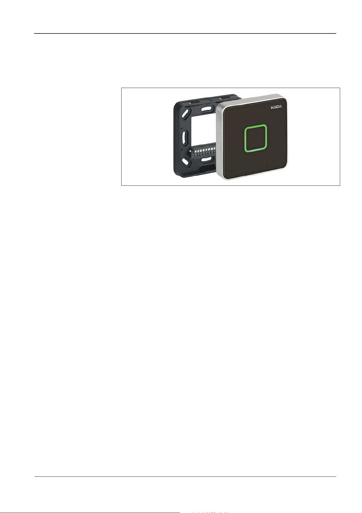
3 Product description
The Kaba compact reader 91 10 is designed as a subterminal to be used on a time
and attendance terminal or for access control unit.
The Kaba compact reader 91 10 is installed in an ergonomically suitable position in
secured indoor areas, e.g. in the access area (door).
The rear panel of the contact reader is installed using a socket for flush mounting or
cavity wall mounting. A rear panel with spacer frame is optionally available for
surface mounting.
The integrated RFID reader allows contact-free reading and writing of RFID media in
MIFARE or LEGIC technology (depending on the version).
Communication with the superior access control system or the time and attendance
terminal is performed in the "Online" operating mode via the RS-485 subpartyline.
Access, IN, or OUT booking operation can be selected.
The device has 2 digital inputs that can be used in combination with an access
control, e.g. for door frame contact or door-opener. The built-in relay can be used for
door opening in secure areas.
The compact reader is equipped with a light icon (red/green) and a buzzer for optical
and acoustic signaling.
Kaba compact reader 91 10 - subterminal 04042573 - 07/2014 9

Product description Technical Manual
3.1 Technical data
3.1.1 Interfaces
RS-485
RS-485 2-wire subpartyline for communication with the superior access control
system unit or a time and attendance terminal.
• Protocol: BPA/9 Subset.
• Automatic baud rate detection; 9600 / 19200 Baud.
• 7 data bits, even parity, 1 stop bit.
Programming interface
For terminal software update.
3.1.2 Power supply
• Voltage range: 12 – 27 V AC; 10 – 34 V DC
3.1.3 Reader
3.1.4 Inputs / Outputs
• Power consumption: Typically 1.2 W; max. 2.2 W
MIFARE version
• RFID standard: ISO 14443A
• Badge media supported:
MIFARE DESfire
MIFARE Classic
LEGIC version
• RFID standard: ISO 14443A, ISO 15693, LEGIC RF
• Badge media supported:
LEGIC advant
LEGIC prime
1 relay output
• One potential-free changeover contact.
• Contact loading capacity: 30 V AC / DC; max. 2 A.
2 digital inputs
• With integrated power supply and common ground to connect potential-free
contacts.
• Input voltage: max. 5 V DC.
10 04042573 - 07/2014 Kaba compact reader 91 10 - subterminal
Technical Manual Product description
5
9
3.1.5 Environmental conditions
• Ingress protection according to IEC 60529:
IP54 (flush cable mounting with sealing pad)
IP40 (surface cable mounting)
• Relative humidity:
0% to 95%, non-condensing
• Ambient temperature:
-25 °C – +70 °C (operation)
-40 °C – +85 °C (storage)
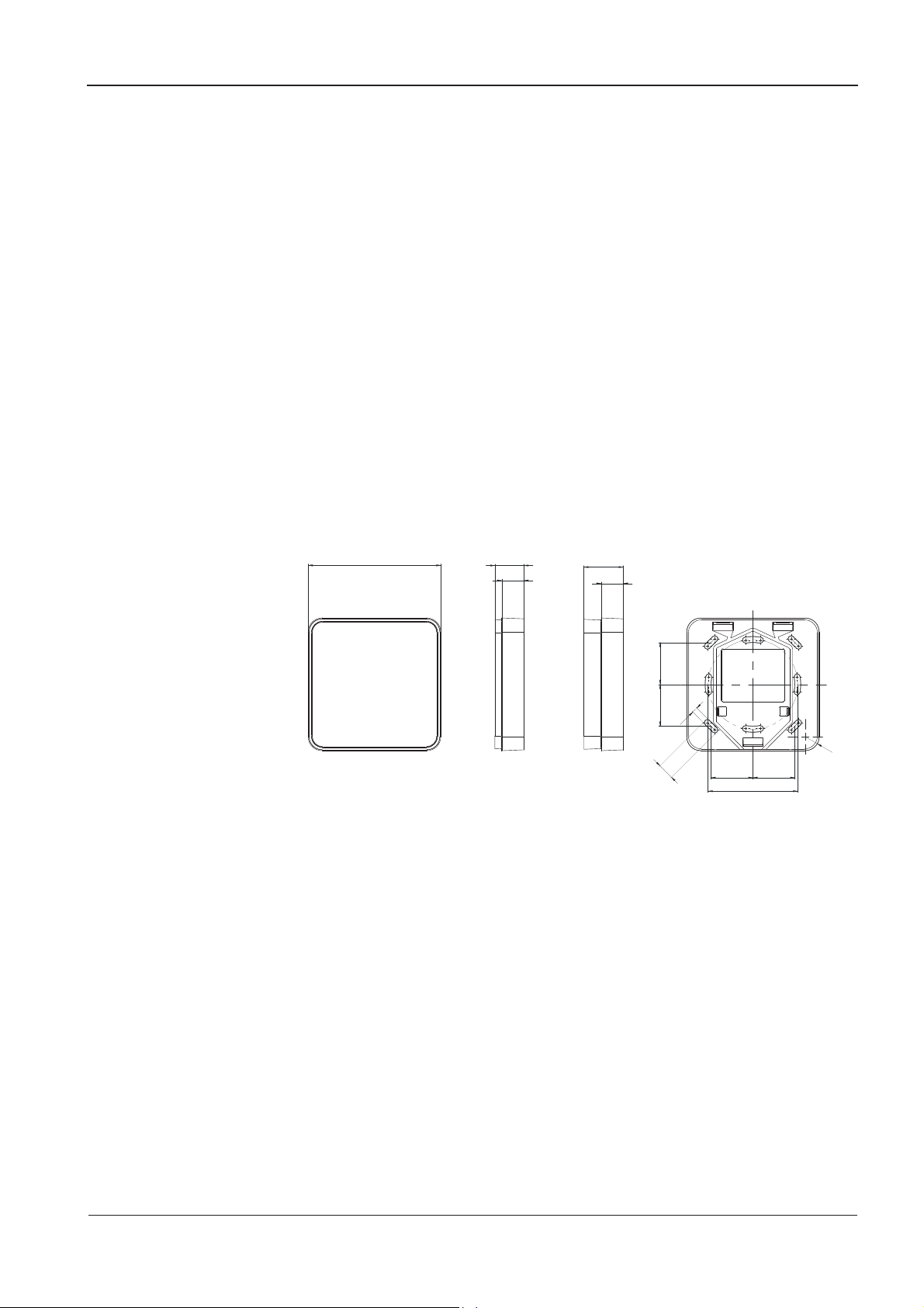
3.1.6 Dimensions
Width x Depth x Height, dimensions in mm
• Compact reader for flush cable mounting: 88.5 x 88.5 / 19.4
• Compact reader for surface cable mounting: 88.5 x 88.5 / 26.4
88,
19,4
14,9
26,4
14,9
2828
4
11
28
Ø 60
28
Kaba compact reader 91 10 - subterminal 04042573 - 07/2014 11

Product description Technical Manual
A
Konf
3.2 Conformity
This device complies with the following standards:
EN 60950-1:2006 + A11:2009
EN 301 489-1 V1.6.1
EN 301 489-3 V1.4.1
EN 300 330-1 V1.3.1
EN 300 330-2 V1.3.1
according to the regulations of the EU Directives
2006/95/EG
1999/5/EG
2004/108/EG
Low voltage directive
R&TTE Directive
EMC Directive
RoHS This device is in conformity with Directive 2011/65/EU of the European Parliament
and of the Council of 8 June 2011 on the restriction of the use of certain hazardous
substances in electrical and electronic equipment.
In addition, the product also conforms to the following standards:
UL 60950-1
UL 294
The components shall be supplied by a limited power source according to chapter
2.5 of IEC 60950-1. When installing/inserting the components in end-use
equipment/system all requirements of the mentioned test standards must be
fulfilled.
The external power supply unit shall be in accordance to UL 294. The secondary
output shall fulfill the requirements for class 2 or class 3 outputs.
UL 294 Security Level 1
FCC ID NVI-KCR9110-L1
This device complies with part 15 of the FCC Rules. Operation is subject to the
following two conditions:
• This device may not cause harmful interference
• This device must accept any interference received, including interference that
may cause undesired operation.
ny changes or modifications not expressly approved by the party responsible for
compliance could void the user's authority to operate the equipment.
12 04042573 - 07/2014 Kaba compact reader 91 10 - subterminal

Technical Manual Product description
3.3 Labeling
The identification plate is located on the rear of the device.
Specified on the identification plate:
• Device name
• Product number
• Serial number
• Power data
• CE identification
• WEEE labeling acc. to DIN EN 50419
Kaba compact reader 91 10 - subterminal 04042573 - 07/2014 13
Design and Function Technical Manual
4 Design and Function
4.1 Device variants
4.1.1 RFID reader
The Kaba compact reader 91 10 is available with the following reader types:
• MIFARE
• LEGIC
4.2 Design
The housing of the compact reader is available in two versions:
• for flush cable mounting with flat rear panel.
• for surface cable mounting with deep rear panel (spacer frame).
4.3 Terminal software
The hardware of the compact reader is used in various Kaba system solutions. Use
and functions of the device are determined by the software used:
This description of the Kaba compact reader 91 10 only refers to the terminal
software for online operation as a subterminal.
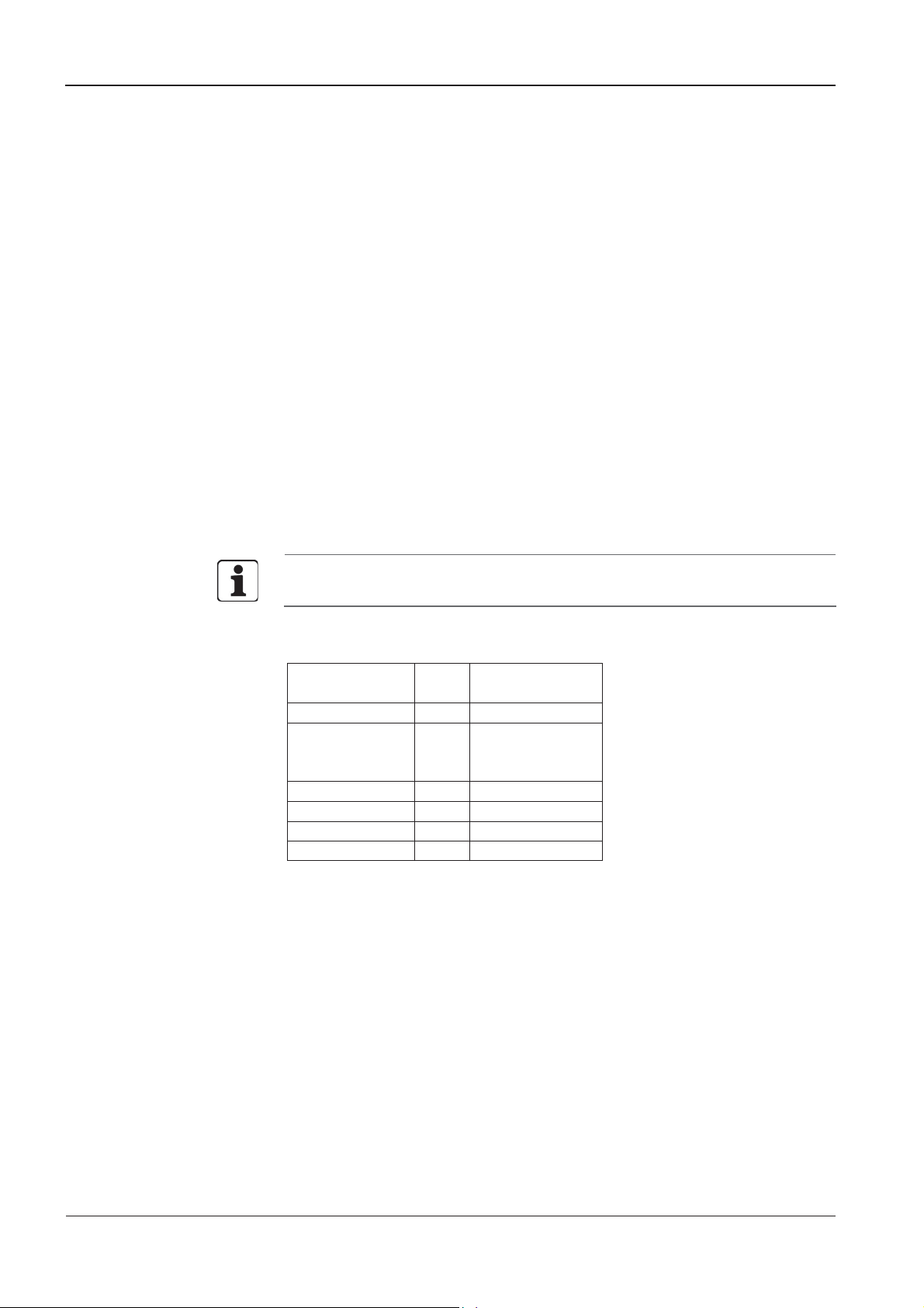
Designation of the terminal software
The software designation has the following meaning:
Reader type
Device type
Operating mode
Version number
Addition 1
Addition 2
Addition 3 _ Reserve
Examples:
MRCC01.08RA_ terminal software for MIFARE compact reader.
ARCC01.05RA_ terminal software for LEGIC compact reader.
M
A
RC
A
B
C
01.00
R
A
MIFARE
LEGIC
Compact reader
Standalone
Access manager
Subterminal
Version
Released
Subversion
Labeling of the device
"Type: Subterminal" is written on the identification plate of devices using the
terminal software for online operation as a subterminal.
14 04042573 - 07/2014 Kaba compact reader 91 10 - subterminal
Technical Manual Design and Function
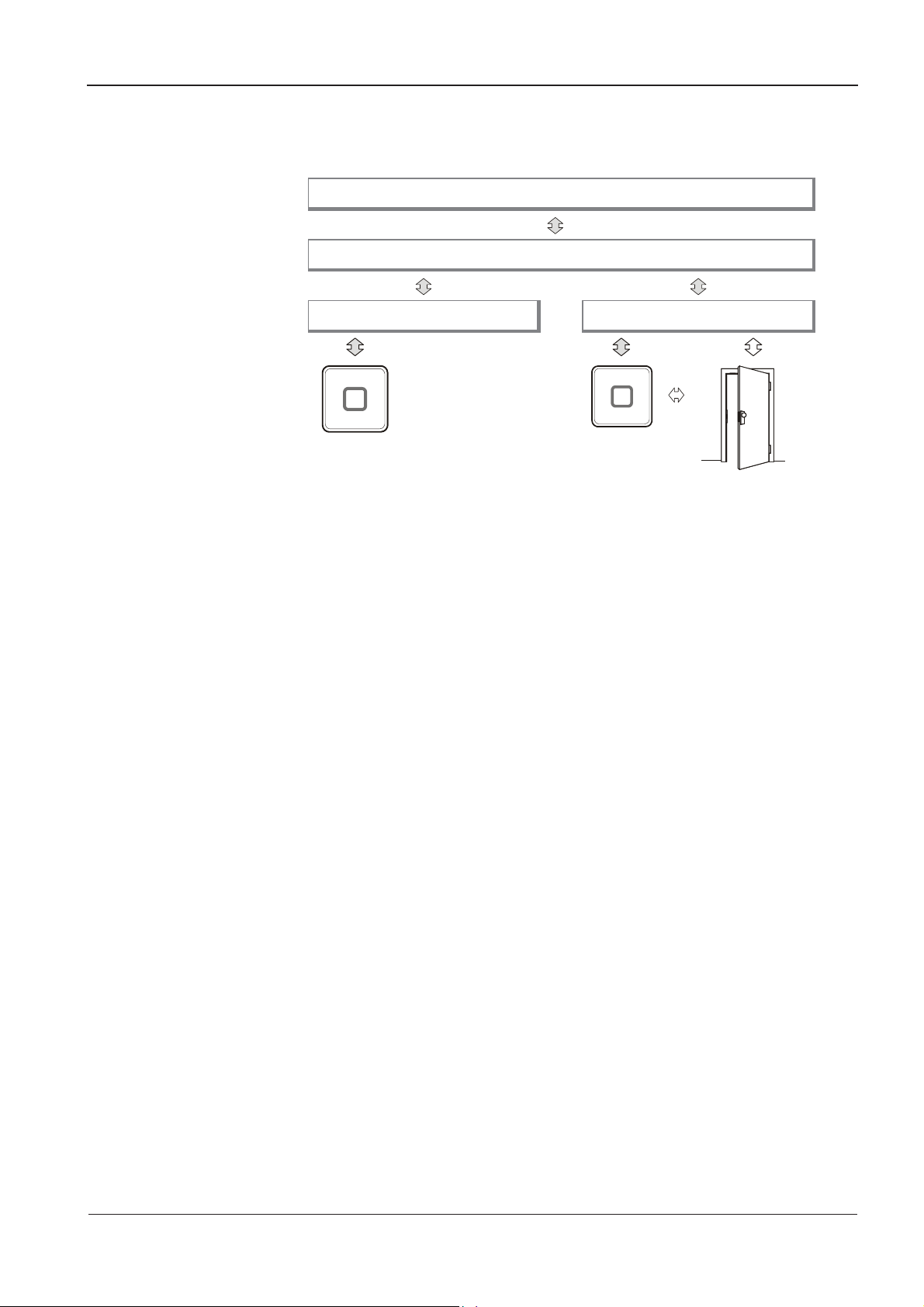
4.4 System connection
Customer application
B-COMM communications software
Time and attendance terminal Access control unit
The compact reader operates as a subterminal of a superior time and attendance
terminal or an access control system, which is called control system in the following
text.
Data exchange takes place via the RS-485 interface (subpartyline). Communication is
realized via the transmission protocol BPA/9 subset.
Once the subterminal has been switched on, it will be initialized. This process
includes setting the parameters of the reader driver, thus defining the method for
transferring badge data into the data record.
Compact reader
The subterminal can be used for Access, IN, or OUT booking operations.
The compact reader itself has no decision-making authority and is to be considered
as a separate operating unit. Once a valid RFID medium (badge) is detected, a
corresponding badge data record will be sent to the control system. The control
system will decide whether a badge is authorized or not and return the respective
commands for signaling (acoustic signal generator and luminous ring) and relay
control to the subterminal.
The built-in relay can be used to trigger the door opener. The inputs may be used for
door monitoring in combination with an access control system.
Kaba compact reader 91 10 - subterminal 04042573 - 07/2014 15

Design and Function Technical Manual
4.5 System requirements
Communication software
• B-COMM version 2.10 and higher
Control
• Terminal of the B-web 93 00 series with B-Client HR10 terminal software
version 754-00-X-K02 and higher.
• B-Net 92 50 access control manager with B-Client AC2 terminal software
version 664-03-X-K03 and higher.
• B-Net 92 90 access control manager with B-Client AC3 terminal software
version 666-03-X-K03 and higher.
• B-Net 92 90-2 access control manager with B-Client AC3 terminal software
version 668-00-X-K04 and higher.
4.6 Supported features
Depending on the system connection, the following functional elements are
supported:
HR = B-web 93 00 time and attendance terminal with B-Client HR10 terminal
software.
AC = Access control unit with B-Client AC2/3 terminal software.
HR AC
Inputs - X
Outputs X X
CardLink update - -
CardLink validation and invalidation - X
Distribution of site keys via download
(ARIOS security concept)
X -
16 04042573 - 07/2014 Kaba compact reader 91 10 - subterminal
 Loading...