

dormakaba EAD E3200 User Manual
Terminal 97 00
Technical Manual
04043552 - 05/2017
DRAFT
EN

dormakaba EAD GmbH
Albertistraße 3
78056 Villingen-Schwenningen
Germany
T: +49 7720 603-0
www.dormakaba.com
Company headquarters: Heiligenhaus
Copyright © dormakaba 2017
All rights reserved.
No part of this document may be reproduced or used in any form or by any means without prior written permission of dormakaba Schweiz AG.
All names and logos of third-party products and services are the property of their respective owners.
Subject to technical changes.
04043552 - 05/2017 DRAFT

Table of Contents
1 About this document 7
1.1 Validity 7
1.2 Target group 7
1.3 Content and purpose 7
1.4 Using the document 8
1.5 Additional documentation 8
1.6 Warnings 9
1.6.1 Hazard categories 9
1.6.2 Symbols 9
1.7 Information 9
1.8 Instructions 10
2 Basic safety information 11
2.1 Proper use 11
2.2 Assembly and installation 11
2.3 Service and maintenance 11
2.4 Accessories and spare parts 11
2.5 Electrical hazards 12
2.6 Handling of lithium batteries 12
2.7 ESD protective measures 13
2.8 Environmental protection 13
Table of ContentsTechnical Manual
3 Product description 14
3.1 Overview 14
3.2 Technical data 15
3.2.1 System 15
3.2.2 Multimedia 15
3.2.3 Interfaces/Communication 16
3.2.4 Reader 16
3.2.5 Inputs/Outputs 16
3.2.6 Power supply 17
3.2.7 Uninterruptible power supply 17
3.2.8 Ambient conditions 17
3.2.9 Dimensions 18
3.3 Conformity 21
3.4 Marking 22
4 Construction and function 23
4.1 Device structure 23
4.1.1 Terminal housing - Front 24
4.1.2 Terminal housing - Rear side 25
4.1.3 Docking station 26
4.1.4 Interface assignment 30
4.1.5 Uninterruptible power supply UPS510 30
4.2 Product versions 31
4.2.1 Basic equipment 31
4.2.2 Optional equipment (not retrofittable) 31
4.2.3 Optional equipment (retrofittable) 31
4.2.4 Accessories 31
4.3 Terminal software 32
4.3.1 BaseApp 32
4.3.2 Kaba test program 32
4.3.3 B-Client HR30 terminal software 32
4.3.4 B-Client HR30 software options 32
4.4 System connection 35
4.4.1 Communication principle 35
304043552 - 05/2017 Terminal 97 00DRAFT

Table of Contents Technical Manual
4.4.2 Parametrization 35
4.4.3 Authorizations 35
4.4.4 Data from the terminal 35
4.4.5 Operating states 36
4.4.6 Devices with biometric reader 36
4.5 Authentication types 37
4.5.1 Mode 1: Identification 37
4.5.2 Mode 2: Verification 37
4.5.3 Mode 3: Verification (ID) 37
4.5.4 Mode 4: Combination of modes 1 and 2 37
4.5.5 Mode 5: Combination of modes 2 and 3 37
4.5.6 Alternative types of authentication 38
4.5.7 Additional PIN entry 38
4.6 CardLink 39
5 Installation 40
5.1 Installation conditions 40
5.1.1 General 40
5.1.2 Installation site 40
5.1.3 Connections 40
5.1.4 Power supply 41
5.1.5 Cable entry 42
5.2 Installation lines 43
5.2.1 24 V DC power supply 43
5.2.2 Mains voltage supply 43
5.2.3 Ethernet 43
5.2.4 Inputs/Outputs 43
5.3 Fastening the docking station 44
5.4 Connections 45
5.4.1 Connecting the network cable 45
5.4.2 Connecting the mains voltage 45
5.4.3 Mains fuses 46
5.4.4 Connecting 24 V DC power supply 47
5.4.5 Digital inputs 48
5.4.6 Relay outputs 49
5.4.7 Connecting an external reader 50
5.5 Uninterruptible power supply UPS510 51
5.6 Fasten the terminal housing to the docking station. 52
6 Commissioning 53
6.1 Network requirements 53
6.1.1 Communication 53
6.1.2 Comparing finger templates 53
6.1.3 Automatic registration via B-COMM 53
6.2 Automatic registration via B-COMM 54
6.2.1 Cancelling automatic registration 54
6.3 Manual settings 55
6.4 Settings via the Kaba test program 56
6.4.1 Service language 56
6.4.2 Reader settings 56
6.5 Service Interface 59
6.5.1 Remote access 59
6.5.2 Accessing the service interface locally from the B-Client HR30
terminal software. 60
6.5.3 Accessing the service interface locally from the BaseApp 61
6.6 Android system settings 62
6.6.1 Network settings 63
6.6.2 Settings for adjustment to the environment 66
6.7 Reader initialization 67
6.7.1 LEGIC 67
6.7.2 MIFARE (ARIOS) 68
6.7.3 MIFARE (Baltech) 68
6.8 SFTP server 69
4 04043552 - 05/2017Terminal 97 00 DRAFT

Table of ContentsTechnical Manual
6.8.1 Preconditions 69
6.8.2 Establishing an SFTP connection 69
6.8.3 Information on the key file 70
6.8.4 Important directories and files 71
6.9 Remote setup 72
7 Operation 73
7.1 Operating elements 73
7.2 Display 73
7.3 Touch screen 73
7.4 Navigation keys 74
7.5 RFID reader 75
7.6 Biometric reader 75
7.7 Swipe reader 76
7.8 Symbols for user guidance 77
7.8.1 Function keys 77
7.8.2 Input prompt 78
7.8.3 Error states 79
7.8.4 CardLink 79
7.8.5 Finger entry 80
7.9 BaseApp 81
7.9.1 Starting the application 81
7.9.2 App management 82
7.9.3 System Information 84
7.10 B-Client HR30 terminal software 85
7.10.1 Starting the terminal software 85
7.10.2 Shutting down the terminal software 86
7.10.3 Info functions 87
7.10.4 Registering new fingerprints at the terminal 88
8 Maintenance 92
8.1 Backup battery 92
8.1.1 Battery change 92
8.2 Replacement of the uninterruptible power supply UPS510 93
8.3 Cleaning the housing 93
8.4 Installation/Update of the terminal software 94
8.4.1 Data backup 94
8.4.2 Preparing installation/update 94
8.4.3 Performing an update 94
8.4.4 Performing the installation 95
8.5 Android update 95
9 Packaging/Returns 96
9.1 Complete devices 96
9.2 Electronic components 96
9.3 Labelling 97
10 Disposal 98
Index 100
504043552 - 05/2017 Terminal 97 00DRAFT

Table of ContentsTechnical Manual
604043552 - 05/2017 Terminal 97 00DRAFT

1 About this document
1.1 Validity
This document describes the product:
Product designation: Terminal 97 00
Product ID: 9700-K6
Item number 04079701
Terminal software: 735-05-X-K02 - B-Client HR30
BaseApp: 771-05-X-K02
Kaba test program 797-05-X-K02
Date of manufacture: From April 2017
About this documentTechnical Manual
This document describes all product versions and all optional features and functions. Options
are subject to a charge and therefore only available if purchased. Additional features and
functions may not be available at the time the document is issued and may only be available
for purchase at a later date.
1.2 Target group
This quick start guide is intended for skilled persons only.
The descriptions are intended for skilled persons trained by the manufacturer. The descrip-
tions are no replacement for product training.
For reasons of equipment safety, the installation, maintenance and service measures de-
scribed in this documentation should only be carried out by skilled persons in accordance with
EN 62368-1 (Audio/Video, Information and Communication Technology Equipment – Part 1:
Safety Requirements).
Skilled person is the designation for people who have the appropriate technical training and
experience in setting up the equipment. Skilled persons are expected to use their training and
experience to identify any risks to themselves and others that may arise while carrying out
these activities, and to minimise these risks as far as possible. It is the skilled person’s responsibility to ensure that the conditions stated by the manufacturer and the applicable regulations and standards are complied with when carrying out these actions.
This documentation is also used to provide information for persons with the following tasks:
• Project planning and implementation
• Putting the product into operation within a network
• Connecting the product to the user software by programming customer applications
• Customer-specific adjustment through parameter setting on the product
1.3 Content and purpose
Content is limited to the assembly, installation, commissioning and basic operation of the
product.
704043552 - 05/2017 Terminal 97 00DRAFT

About this document Technical Manual
1.4 Using the document
To make it easier to find specific topics, please refer to the following document guidelines:
• The contents list at the start of the document provides an overview of all topics.
• The headings also list the relevant main chapter.
• Cross-references provide the number of the chapter in which more information can be
found. Example [ 5.7].
• There is an alphabetical index at the end of the document.
1.5 Additional documentation
Specific parametrization of the terminal software:
• B-Client HR30 reference manual
Web interface for commissioning:
• Service interface reference manual
Kaba ARIOS security concept and required system adjustments for different MIFARE media:
• Kaba MIFARE adjustments reference manual
Supplementary documentation is available on the Kaba website. Technical manuals can be
found in a secured area of the website.
• Access is only granted after a valid login.
• An account must be set up before logging in for the first time.
Opening login screen:
1. Open your internet browser and go to http://www.kaba.com.
2. Choose your language in the top right-hand corner of the screen.
3. Under 'Products', choose either the 'Access Management' or 'Workforce Management'
product division.
4. In the top right-hand corner of the screen, click on the following symbol:
5. Enter your email address and password to log in or create a new account (see below).
ð The technical manuals can be found under 'Downloads'.
Creating an account:
1. Click 'Create account'.
2. Fill in the data fields and confirm your entries.
ð A confirmation link will be sent to your email address.
3. Click on the confirmation link in your email to activate your account.
8 04043552 - 05/2017Terminal 97 00 DRAFT
1.6 Warnings
Warnings with information, instructions and forbidden actions to prevent personal injury and
material damage are highlighted.
Please note the warnings! These are intended to help avoid accidents and prevent damage.
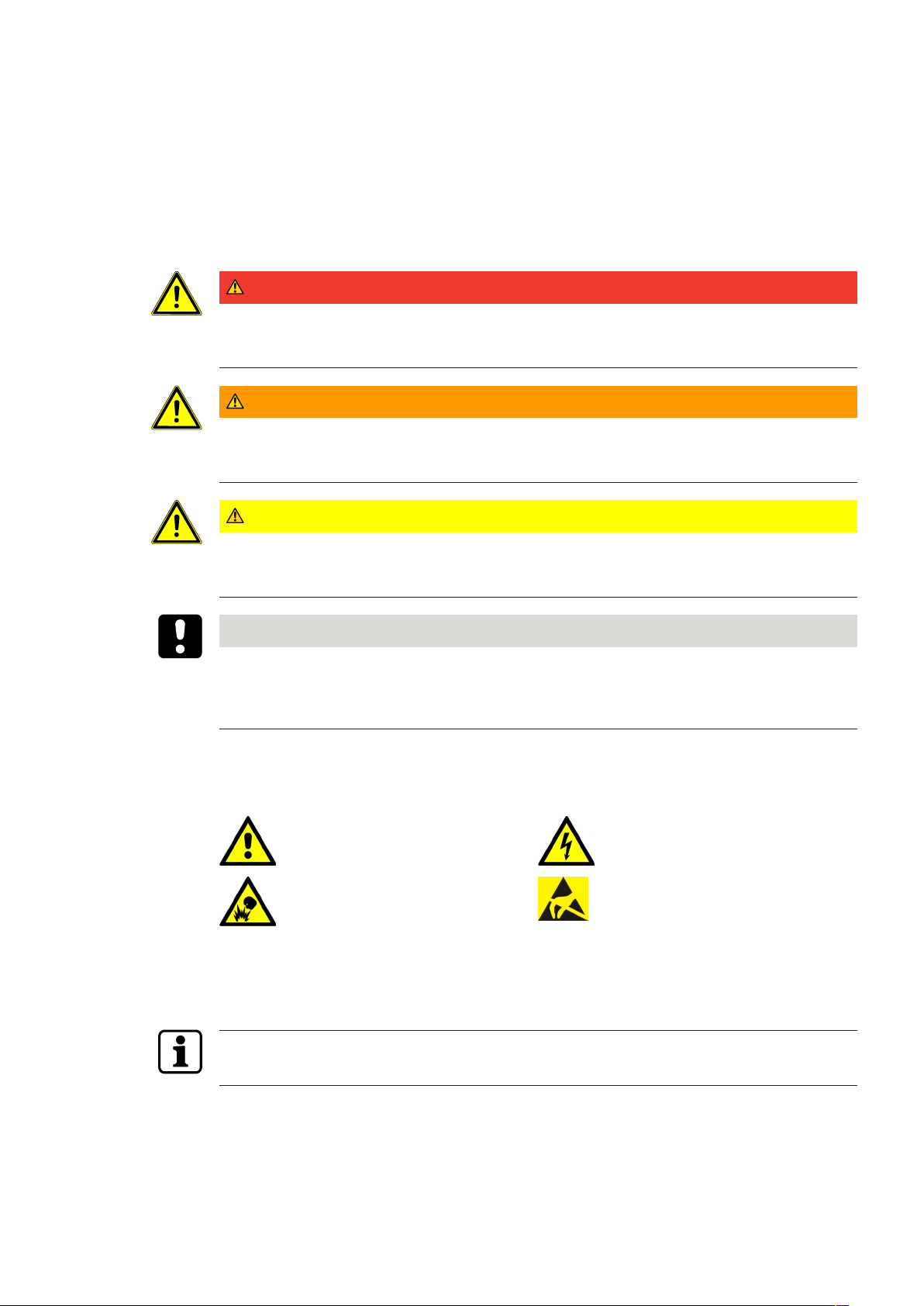
1.6.1 Hazard categories
Warnings are divided into the following categories:
DANGER
High risk
Designates an imminent danger resulting in serious injuries or death.
WARNING
Medium risk
Designates a potentially dangerous situation which can result in serious injuries or death.
About this documentTechnical Manual
CAUTION
Low risk
Indicates a potentially dangerous situation that can lead to minor injury.
NOTICE
Important information about the correct use of the product.
Non-adherence to the notes can lead to malfunctions. The product or something in its vicinity
could be damaged.
1.6.2 Symbols
Depending on the hazard source, the following symbols are used for warnings.
General hazard Hazard caused by electric power
Risk of explosion Risk to electronic components
caused by electrostatic discharge
1.7 Information
Information is designated by an info symbol.
Tips for usage, useful information.
These help to make the best use of the product and its functions.
904043552 - 05/2017 Terminal 97 00DRAFT

About this document Technical Manual
1.8 Instructions
Structure and symbols of the instructions are illustrated in the following example:
ü Prerequisite
1. Step 1
ð Interim result
2. Step 2
ð Result
10 04043552 - 05/2017Terminal 97 00 DRAFT

2 Basic safety information
This product has been built according to the latest technology and accepted safety regulations. Nevertheless, handling this product can pose a risk to people and property.
Read and observe the following safety information before using the product.
2.1 Proper use
This product has been designed exclusively for use as set out in the chapter Product Description. Any other use will be deemed improper use. The manufacturer accepts no liability for any
resulting damage. The user/operator bears sole responsibility for the risk.
2.2 Assembly and installation
Check the device for visible damage caused by transport or wrong storage. Do not start up
any damaged device!
Basic safety informationTechnical Manual
Assembly and installation of the product may only be done by skilled personnel (see chapter 1
Target group).
Mains voltage installations may only be carried out by a certified specialized company or authorized electricians.
The product should only be installed in locations which fulfil the environmental and technical
conditions specified by the manufacturer.
The manufacturer is not liable for damage arising due to improper handling or incorrect installation.
2.3 Service and maintenance
Conversions and modifications to the product may only be done skilled personnel (see chapter
1 Target group). Any conversions and modifications performed by other persons will exempt
us from any liability.
The elimination of faults and maintenance work may only be performed by skilled personnel
(see chapter 1 Target group).
2.4 Accessories and spare parts
Accessories and spare parts must comply with the technical requirements of the manufacturer. This is guaranteed with dormakaba original accessories and spare parts.
1104043552 - 05/2017 Terminal 97 00DRAFT
Basic safety information Technical Manual
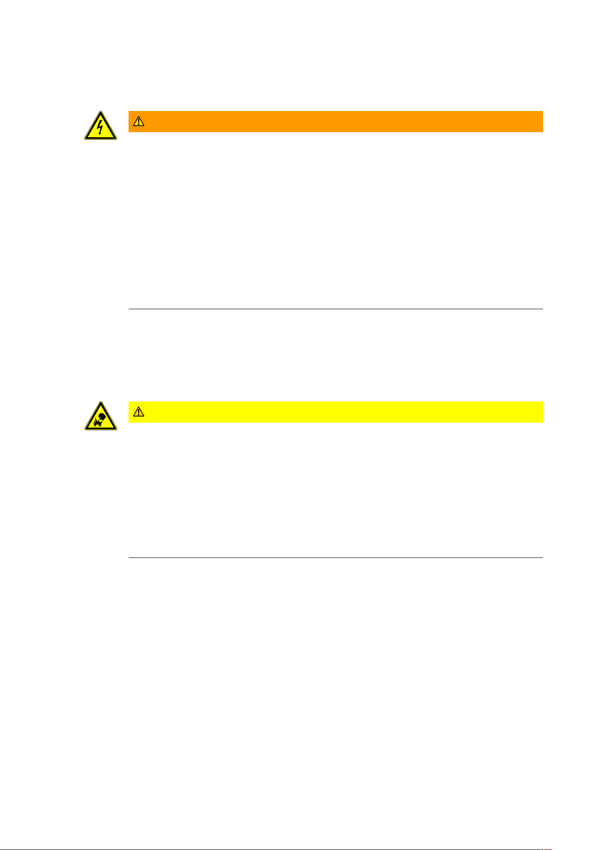
2.5 Electrical hazards
Installations involving the mains power may only be executed by approved specialist companies or authorized skilled electricians.
WARNING
Live connections at the docking station in devices equipped with integrated power supply unit
(BEX120 motherboard)
Carelessness can result in an electric shock.
ü The terminal housing may only be removed from the docking station by skilled personnel.
• Before removing the terminal housing from the docking station, the device must be de-energized.
• For permanently connected devices, the voltage must be switched off.
• For devices supplied by a separable connection, the mains plug must be pulled.
• Secure against being switched on again.
• Check for absence of voltage.
2.6 Handling of lithium batteries
To back up the real-time clock RTC, the device is equipped with a lithium manganese dioxide
battery type CR2032.
The battery is located on the rear side of the terminal housing.
CAUTION
Lithium batteries can explode or burst explosively.
Improper handling of lithium batteries may result in fires and explosions.
• Replace lithium batteries only with batteries of the same type.
• Do not open, drill through or squash lithium batteries.
• Do not burn lithium batteries or expose them to high temperatures.
• Do not short-circuit lithium batteries.
• Do not recharge lithium batteries.
12 04043552 - 05/2017Terminal 97 00 DRAFT

2.7 ESD protective measures
NOTICE
Danger of damage to electronic components from electrostatic discharge.
If electronic printed circuit boards and components are handled incorrectly, damage may occur which leads to their complete breakdown or sporadic faults.
• When installing and repairing the product, the general ESD protective measures are to be
observed.
• When handling electronic components, wear the ESD wrist strap. Connect the end of the
strap to an ESD socket or an unpainted, earthed metal component. This will safely and effectively conduct charges away from your body.
• Only handle the edges of printed circuit boards. Do not touch printed circuit boards or
connecting plugs.
• Put removed components on an anti-static surface or in an anti-static shielding container.
• Avoid contact between printed circuit boards and clothing. The wrist strap only protects
the printed circuit boards from static electricity on the body. Damage can still occur due
to static electricity on clothing.
Basic safety informationTechnical Manual
• Only transport and ship removed modules in ESD-shielding, conductive protective containers.
2.8 Environmental protection
It is prohibited to dispose of the device in your domestic waste.
Used devices contain valuable materials that should be recycled. Properly dispose of used
devices.
Dispose of consumed batteries in accordance with state and local regulations.
Carefully store the batteries to be disposed of to avoid short circuits, crushing or destruction
of the battery casing.
1304043552 - 05/2017 Terminal 97 00DRAFT
Product description Technical Manual
3 Product description
3.1 Overview
The terminal 97 00 can be used for time and attendance and for providing customer-specific
information and applications.
The operating system used of the terminal 97 00 is 'Android’. This allows applications, socalled apps, to be used flexibly at the terminal. The system can be expanded at any time to
make it suitable for a wide range of tasks or also be supplemented by apps specifically developed for customer requirements.
For time and attendance, the B-Client HR30 terminal software is available. This terminal
software makes the device compatible in terms of data records with its predecessor series Bweb and B-net, allowing it to be connected to the host system via UDP using the communication software B-COMM. Connecting it to HTTP/HTTPS-based applications, such as b-comm
ERP5, b+ or EACM, is also possible.
To display information, the terminal is equipped with a 7' colour display with a resolution of
800 x 480 pixels.
The device is equipped with a touch screen operated by touching the glass front.
The time data is recorded by a RFID proximity reader and/or a biometric CBM reader (de-
pending on design)
A proximity sensor activates the device in the sleep or standby mode.
The terminal is equipped with an integrated microphone and an integrated loudspeaker and,
optionally, with a camera system.
Communication takes place via Ethernet. Alternatively and optionally, communication can
also take place via UMTS or WLAN.
Optionally, 2 outputs (relays) and 4 digital inputs are available for control functions.
14 04043552 - 05/2017Terminal 97 00 DRAFT

3.2 Technical data
3.2.1 System
Operating system
• Android version 5.0.2 (Lollipop)
CPU
• BECO620 single-board CPU unit
Memory
• 2 GByte DDR3 RAM
• 8 GByte eMMC Flash
• Card slot for microSD or microSDHC card
Parameters and data records are retained without supply voltage.
RTC
The device has an integrated real-time clock. The function of the RTC is ensured for about 2
years by a lithium battery type CR2032 (on the rear side of the device) even without power
supply of the device.
Product descriptionTechnical Manual
Display
• TFT LCD display module
• Size: 17.8 cm (7.0”)
• Resolution: 800 x 480 pixels (16:9/WVGA)
• Colour depth: 24-bit (true colour)
• Backlit with white LED
Touch screen
• 7” PCAP touch screen over the complete display
• 10-finger multitouch support
• Resolution: 30 x 18 (x/y)
• Optional splinter protection
Biometric proximity sensor
• Optic proximity sensor for activating the biometric reader (option)
• Range 10-50 mm, sensitivity adjustable in 3 steps, can be switched off
Terminal proximity sensor
• Activates the device from the sleep or standby mode when approaching it within approx.
0.5 m
3.2.2 Multimedia
Camera (option)
• Integrated ¼ inch camera; resolution 5 megapixels
Audio
• Integrated microphone
• Integrated loudspeaker with power amplifier (3 W)
• 3.5 mm line-out jack
1504043552 - 05/2017 Terminal 97 00DRAFT

Product description Technical Manual
3.2.3 Interfaces/Communication
Ethernet interface
• IEEE802.3 compatible10BASE-T/100BASE-TX /1000BASE-T Auto sensing, Auto MDIX
• IEEE802.1x security concept, EAP type MD5
WLAN (option)
• Mini PCIe WLAN adapter conforming to IEEE802.11 b/g/n (2.4 GHz)
• Encryption: WPA-PSK, WPA2-PSK and WEP security
Mobile radio (option)
• Mini PCIe HSPE module
• UMTS/HSPA: 850/900/1900/2100MHz
• GSM/GPRS/EDGE: 850/900/1800/1900 MHz
Serial interface RS-232 (option)
• Baud rates: 9600/19200/38400/57600/115200
• Hardware handshake (RTS/CTS)
USB
• 1 x USB 2.0 (host); 5 V/500 mA;
for example for connecting an external reader
3.2.4 Reader
Depending on model, the device supports the following readers:
RFID reader
• MRD - LEGIC prime/advant, MIFARE Classic/DESFire
• HID - iCLASS SE, iCLASS, Prox, Prox II
• HITAG - EM4102, HITAG1, HITAG2
Biometric fingerprint reader
• Biometric module (CBM) with integrated database for fingerprints.
• Optionally as CBM-E with extended approvals (PIV-IQS with FBI certification and FIPS
201 approved template evaluation)
• Depending on model, the reader has a storage capacity for 500, 3000 or 5000 persons (2
fingers per person)
Swipe reader in substructure housing
• Magnetic stripe tracks 1, 2, 3
• Red light barcode
• Infrared barcode
3.2.5 Inputs/Outputs
2 relay outputs (option)
• One potential-free switchover contact each
• Contact loading capacity: 30 V AC/DC; max. 2 A
4 digital inputs (option)
• Galvanically isolated from system
• Input voltage: max. 30 V DC, min. -30 V DC
16 04043552 - 05/2017Terminal 97 00 DRAFT
3.2.6 Power supply
For the power supply of the device, the following alternatives are possible:
• PoE (Power over Ethernet)
• Mains power input (docking station with BEX120 motherboard required)
• 24 V DC power supply (docking station with BEX121 motherboard required)
PoE (Power over Ethernet)
Power supply of the terminal via the 8-wire Ethernet cable (max. 100 m)
• In accordance with IEEE802.3at/type 1 class 0 (0,44-12,95 W)
• Supported feed processes: Spare pair feed and phantom feed
Mains voltage input
• Voltage range: 100–240 V AC
• Frequency: 50/60 Hz
• Current consumption: max. 200 mA
24 V DC power supply
• Voltage range: 22–30 V DC
Product descriptionTechnical Manual
• Current consumption: max. 1 A
Only power supply units that fulfil the following requirements may be used for power supply:
LPS (Limited Power Source) and SELV (Safety Extra Low Voltage) in accordance with IEC/
EN/UL/CSA 60950-1 or ES1 and PS2 in accordance with IEC/EN/UL/CSA 62368-1.
3.2.7 Uninterruptible power supply
UPS510 (option)
The UPS510 consists of an electronic part with charging circuit and a rechargeable battery.
The components are housed in a self-contained housing. Uninterruptible operation of the
device in case of power supply failure is ensured by an NiMH battery with a capacity of 2100
mAh. The battery is fully charged after a charging time of 10 hours.
The UPS510 ensures operation in case of power supply failure for up to 30 minutes or approx.
200 bookings, whatever occurs first.
Condition: New battery, 100% charged, temperature 20 ° - 25 °C.
3.2.8 Ambient conditions
Ingress protection according to IEC 60529
• IP20 (devices with swipe reader)
• IP40 (devices with RFID and CBM readers)
Prerequisite: Cable entry from below using the enclosed grommets
Relative humidity
• 5% - 85%, non-condensing
Ambient temperature
• -5 °C – +45 °C (operation without UPS)
• 0 °C – +40 °C (operation with UPS)
• -25 °C – +70 °C (storage without UPS)
• -20 °C – +45 °C (storage with UPS)
1704043552 - 05/2017 Terminal 97 00DRAFT

Product description Technical Manual
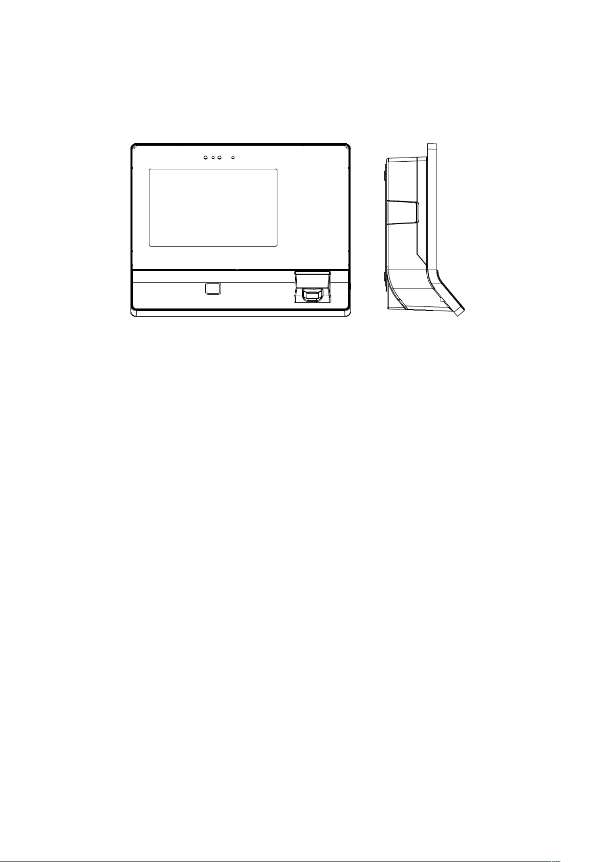
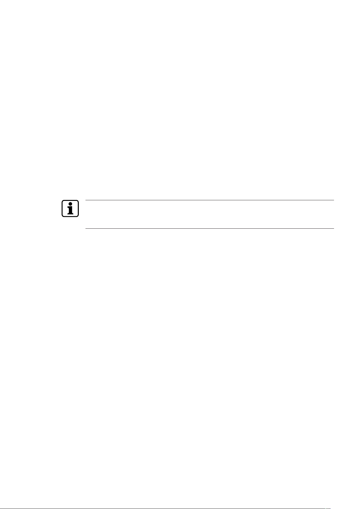
3.2.9 Dimensions
all dimensions are given in mm.
3.2.9.1 Terminal housing
3.2.9.2 Terminal with substructure housing
18 04043552 - 05/2017Terminal 97 00 DRAFT
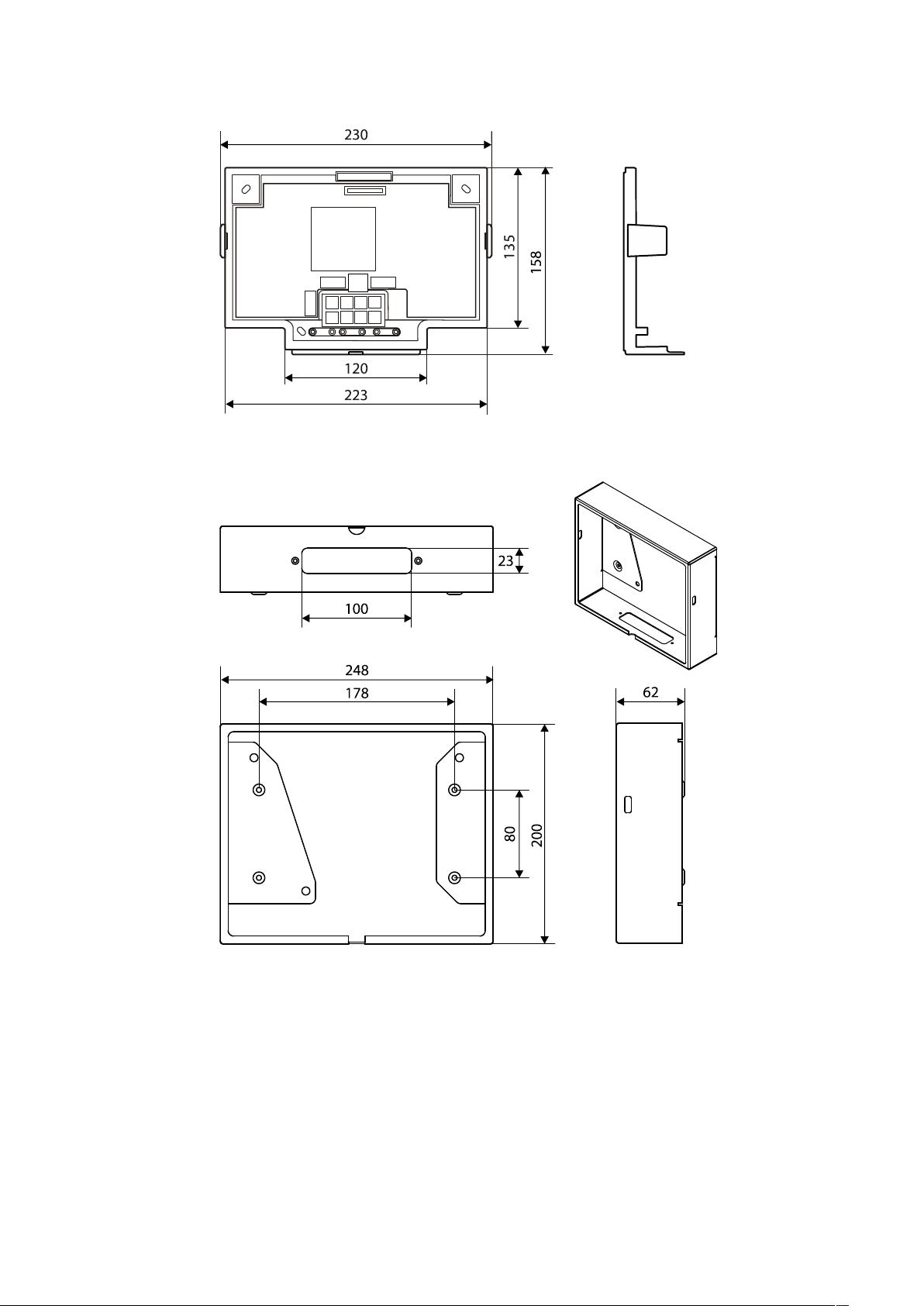
3.2.9.3 Docking station
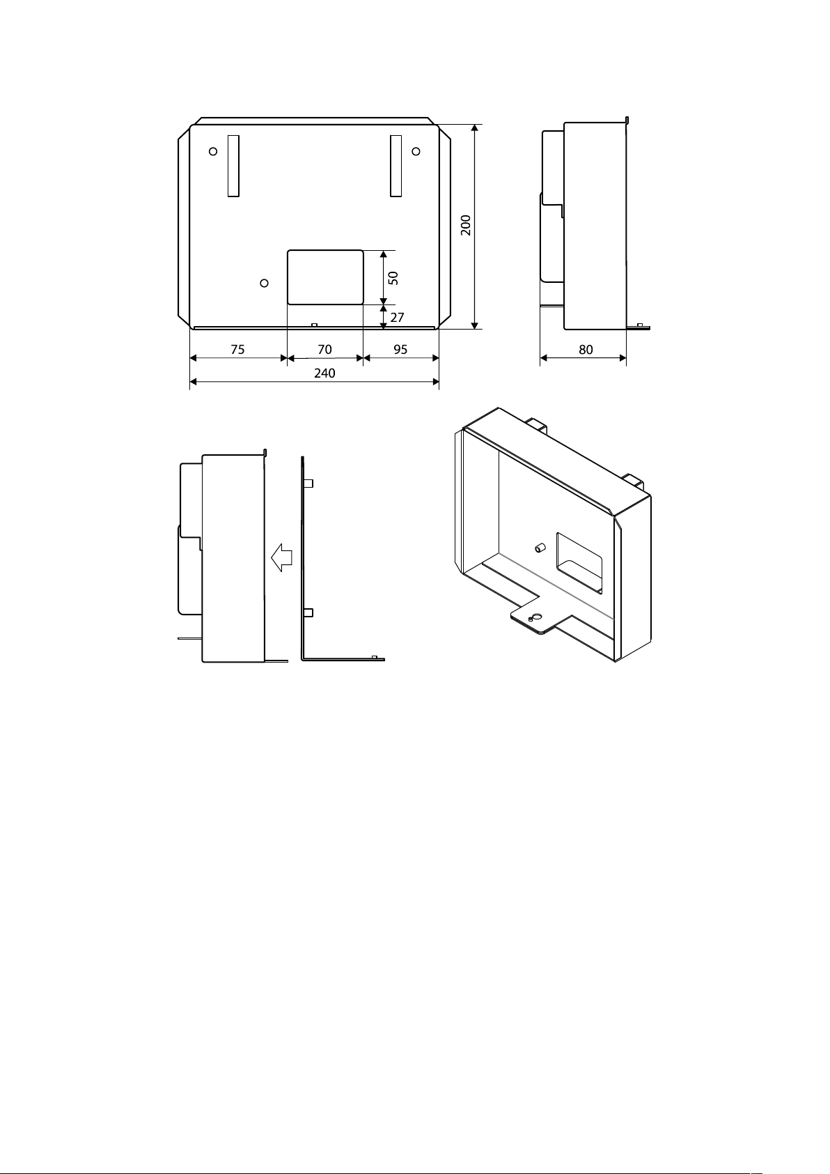
3.2.9.4 Surface-mounted protective metal housing (accessories)
Product descriptionTechnical Manual
1904043552 - 05/2017 Terminal 97 00DRAFT
Product description Technical Manual
3.2.9.5 Flush-mounted housing (accessories)
20 04043552 - 05/2017Terminal 97 00 DRAFT
3.3 Conformity
This product conforms to the following standards:
EN 62368-1:2014
EN 55032:2015
EN 55024+A1:2015
according to the provisions of the EU directives
2014/35/EU - Low Voltage Directive (LVD)
2014/30/EU - Electromagnetic Compatibility (EMC)
The RFID readers MRD (LEGIC & MIFARE) and HID iCLASS SE / Prox used in this product
comply with the following standards
EN 300330-2 V1.6.1
EN 301489-3 V1.6.1
according to the provisions of the EU directive
2014/53/EU - Radio Equipment Directive (RED)
Product descriptionTechnical Manual
RoHS This device complies with the regulations of the Directive 2011/65/EU of the European Parlia-
ment and of the Council of June 8, 2011, on the restriction of the use of certain hazardous
substances in electrical and electronic equipment.
The original conformity declaration can be downloaded in PDF format from www.kaba.com/
conformity.
In addition, the product also complies with the following standards
UL60950-1:2007/R:2014-10
CAN/CSA-22.2 No. 60950-1:2007/A2:2014-10
UL62368-1:2014-12
CAN/CSA-22.2 No. 62368-1:2014-12
FCC Code of Federal Regulations,
CFR 47, Part 15,
Sections 15.107 and 15.109 (Class B)
IC Industry Canada Radio Standards Specifications
ICES-003 Issue 5, Sections 5(a)(i) and 5(b)(i) Class B (ITE)
The RFID readers MRD (LEGIC & MIFARE) and HID iCLASS SE / Prox used in this product
comply with the following standards
FCC Code of Federal Regulations,
CFR 47, Part 15, Sections 15.207, 15.209, 15.215 and 15.225
IC Industry Canada Radio Standards Specifications
RSS-GEN Issue 4, Sections 8.8, 8.9, 8.10 and
RSS-210 Issue 8, Section A2.6 (Category I Equipment)
2104043552 - 05/2017 Terminal 97 00DRAFT
Product description Technical Manual
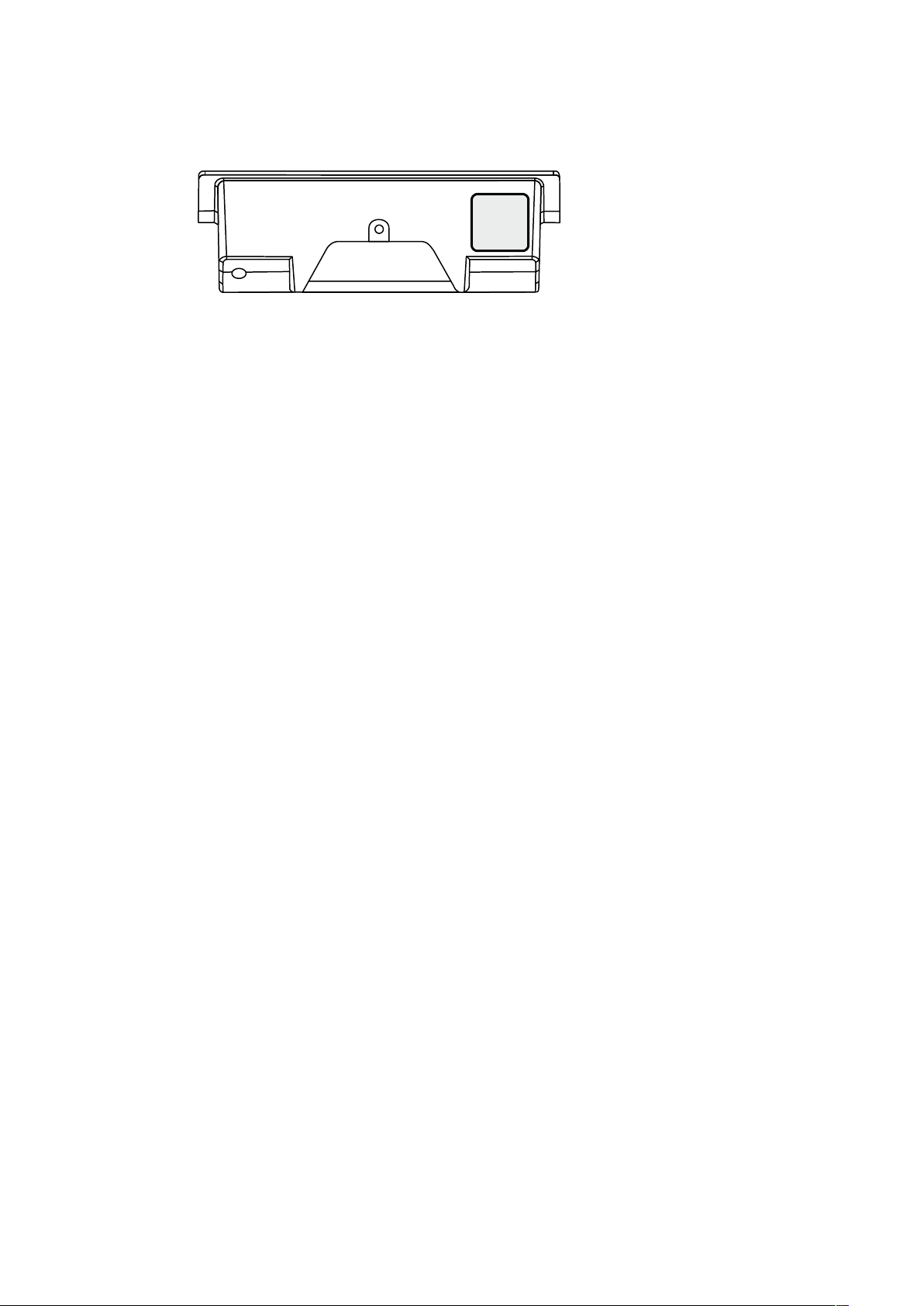
3.4 Marking
The rating plate is located on the underside of the device.
Information given on the rating plate:
• Designation of the device
• Item number
• Serial number
• Date of manufacture
• Connection data (supply voltage)
• CE marking
• WEEE marking according to DIN EN 50419
22 04043552 - 05/2017Terminal 97 00 DRAFT
4 Construction and function
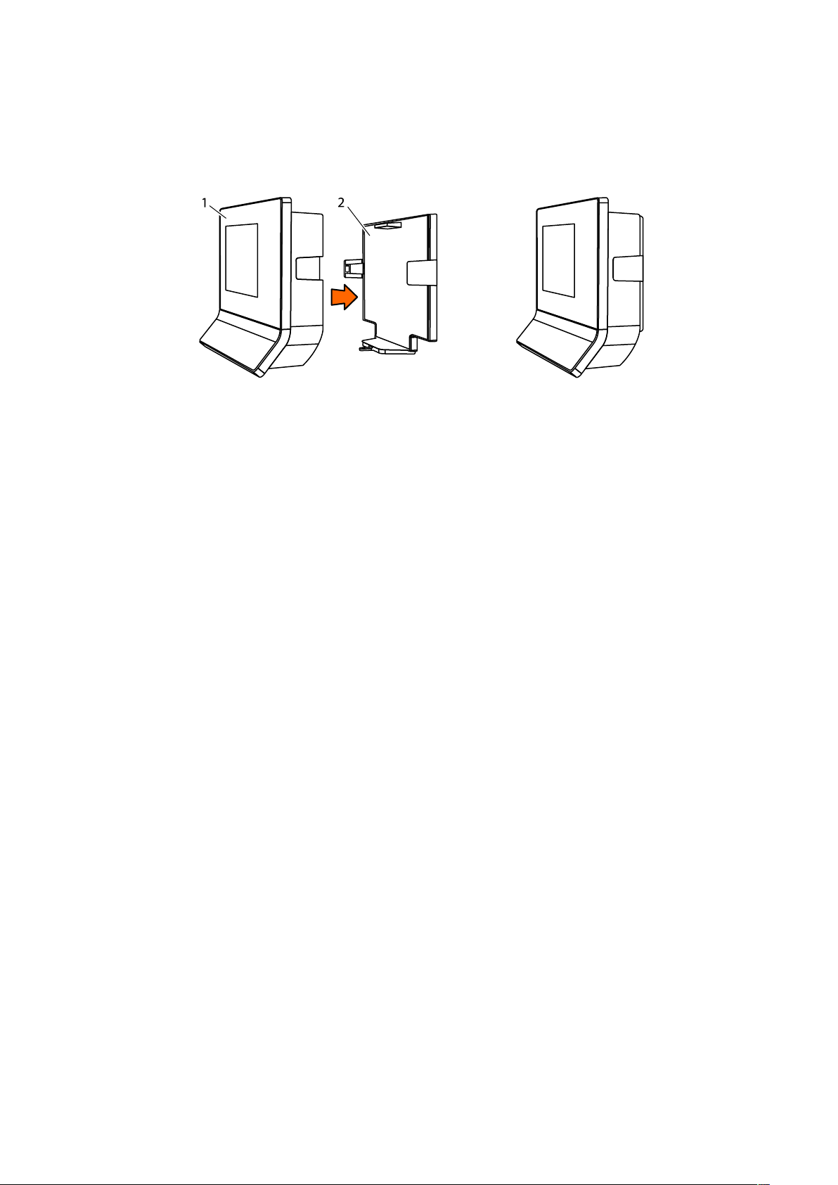
4.1 Device structure
The device consists of the terminal housing (1) and the docking station (2).
The docking station is the wall mounting element of the device and, depending on the equip-
ment, the docking station contains additional electronics.
Construction and functionTechnical Manual
2304043552 - 05/2017 Terminal 97 00DRAFT
Construction and function Technical Manual
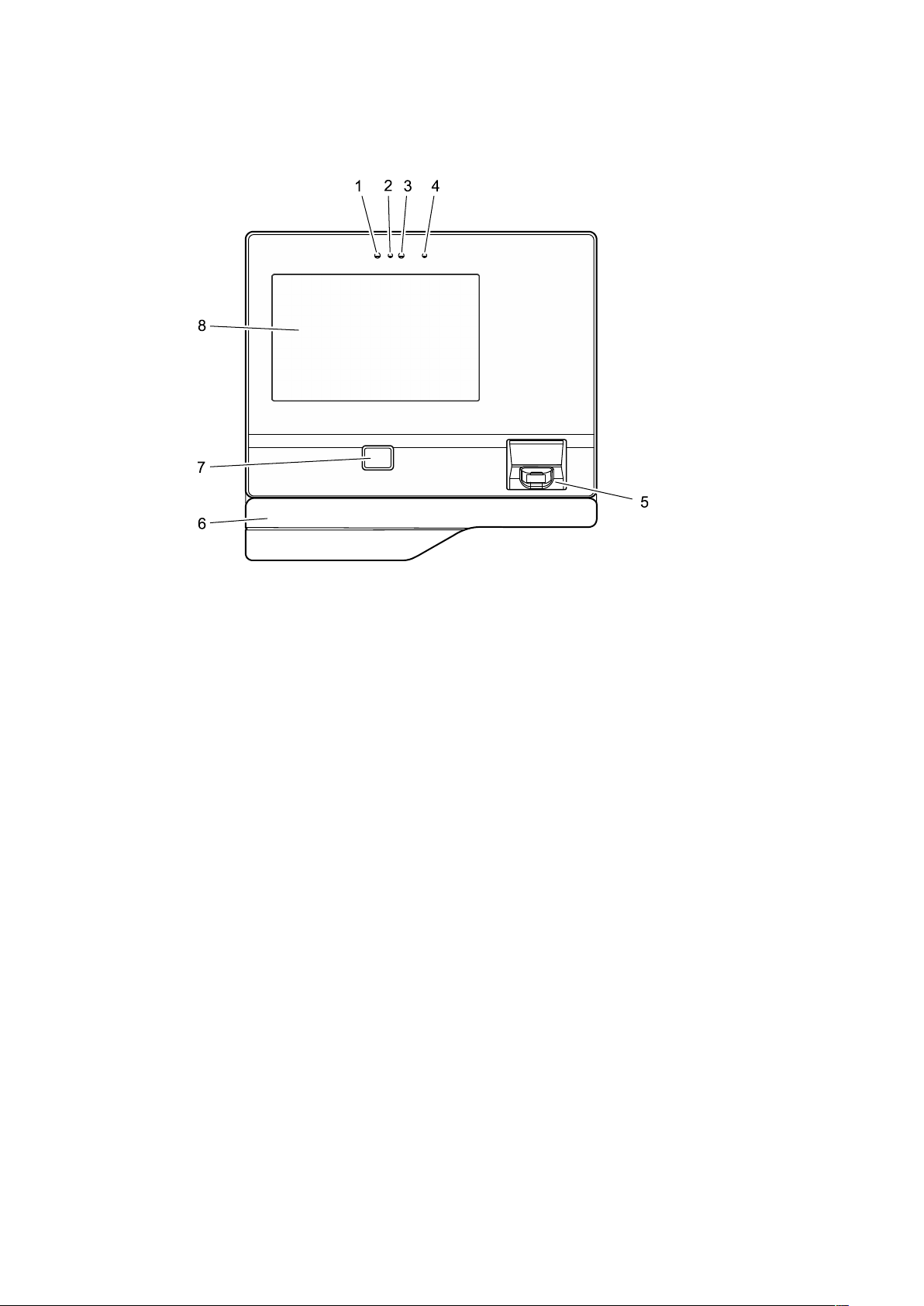
4.1.1 Terminal housing - Front
The terminal housing is the core device. The terminal housing essentially contains the CPU, the
TFT display with touch screen and up to two internal readers.
1 Integrated camera (option)
2 Camera flash (option)
3 Proximity sensor
4 Infrared LED for proximity sensor
5 Biometric reader (option)
6 Substructure housing with alternative RFID reader or swipe reader (option)
7 RFID reader (option)
8 TFT LCD display with PCAP touch screen
24 04043552 - 05/2017Terminal 97 00 DRAFT
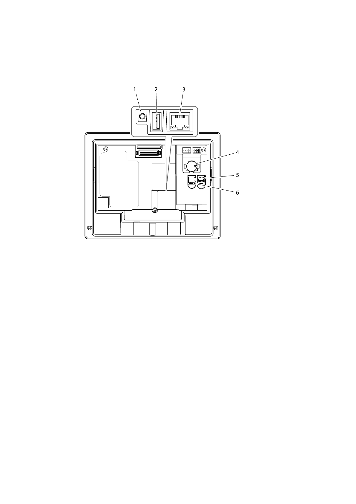
4.1.2 Terminal housing - Rear side
After removing the terminal housing from the docking station, the terminal rear side becomes
accessible.
The rear side of the terminal housing contains, among other things, the connection area and
card slots.
Construction and functionTechnical Manual
1 Audio line-out (3.5 mm jack)
2 USB port
3 Ethernet port (RJ45 socket)
4 CR2032 lithium battery for back-up of the RTC real-time clock
5 Card slot for a micro SIM card
6 Card slot for a microSD or microSDHC card
2504043552 - 05/2017 Terminal 97 00DRAFT
Construction and function Technical Manual
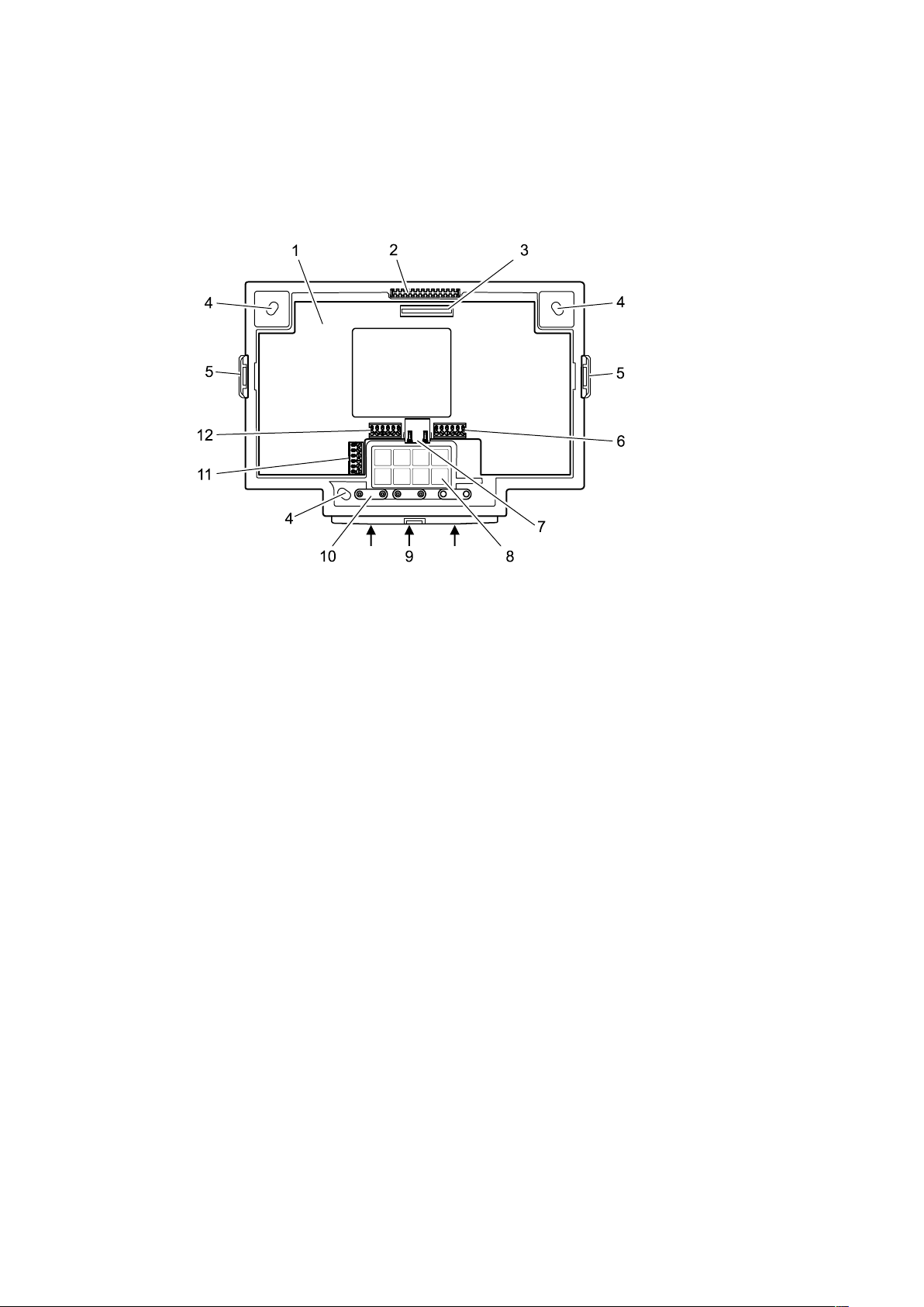
4.1.3 Docking station
The docking station is the wall mounting element of the device and is part of the standard
equipment. The docking station is fastened to the wall. The terminal housing is placed on the
docking station and secured.
The docking station has cut-outs for entry of the installation cables. The installation cables
can be entered from below and from the rear.
1 Motherboard (option)
2 Locking pin for the terminal housing
3 Motherboard/terminal housing contact
4 Long holes for wall mounting
5 Snap-in retaining tabs for the terminal housing
6 Connection terminal for the relay outputs
7 RJ45 connection for an external reader via RS-232
8 Cut-outs for cable entry from the rear
9 Cut-outs for cable entry from below
10 Cable clamps
11 Connection terminal for the additional interface (option)
12 Connection terminal for the inputs
26 04043552 - 05/2017Terminal 97 00 DRAFT
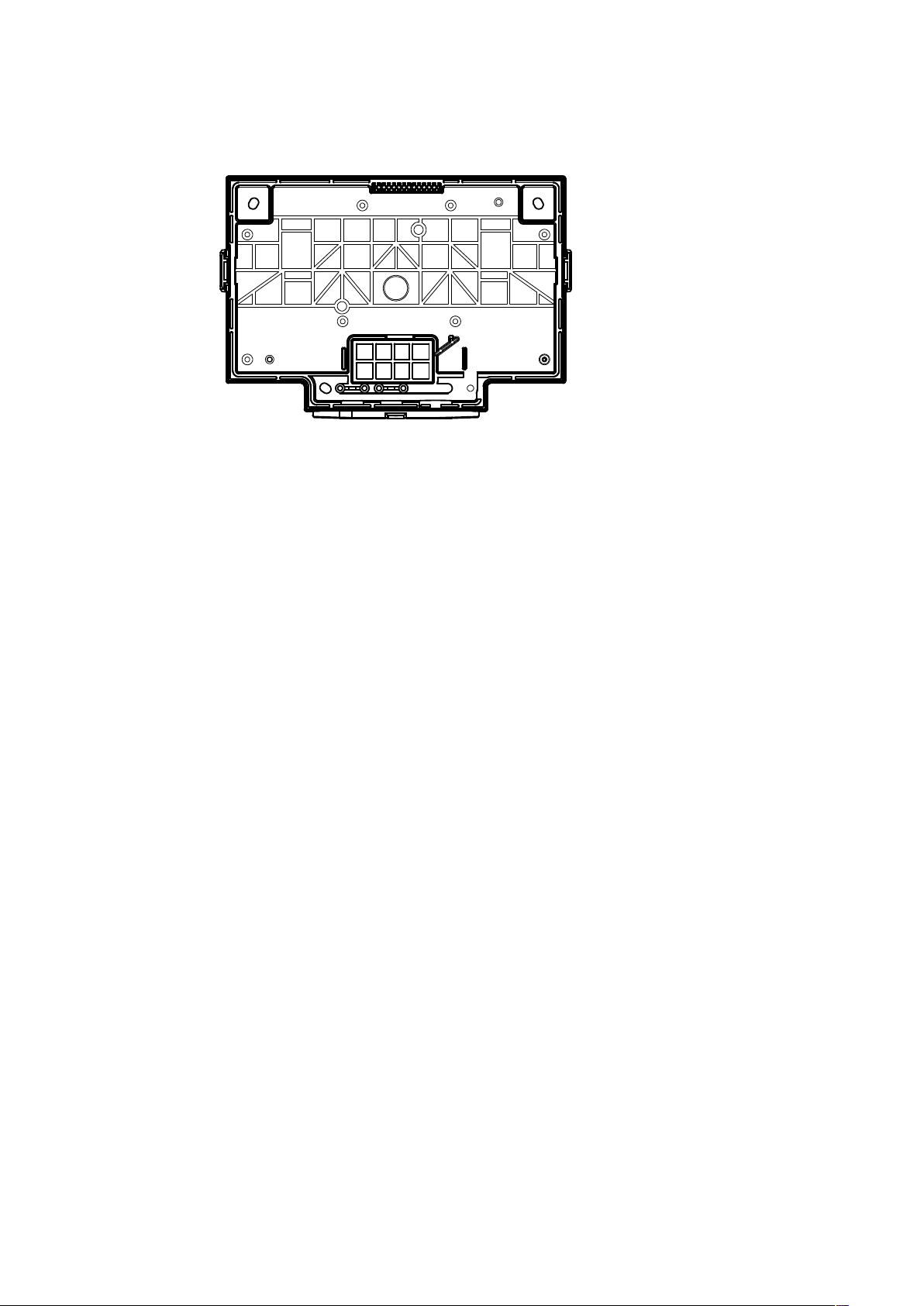
4.1.3.1 Docking station without motherboard
In its basic equipment, the docking station does not include any electronics. In this case, the
docking station serves as pure wall mounting element.
Communication takes place via the Ethernet network. The device is supplied with power via
PoE (Power over Ethernet). This is why only the network cable has to be connected to the terminal housing.
Construction and functionTechnical Manual
The network cable can be introduced into the docking station from the rear or from below.
2704043552 - 05/2017 Terminal 97 00DRAFT
Construction and function Technical Manual
4.1.3.2 Docking station with motherboard
Optionally, the docking station is equipped with a motherboard.
The motherboard is available in 3 different versions. The differences refer to the design of the
power supply. Otherwise, the motherboards are identical.
• BEX122 motherboard - Power supply via PoE
• BEX121 motherboard - Power supply by 24 V DC
• BEX120 motherboard - Power supply by mains voltage
In general, the motherboard has the following hardware equipment:
RS-232C interface
The RS-232C interface can be used for connecting an external reader, for example a CCD barcode scanner.
It is connected to the RJ45 socket of the motherboard.
Additional interface
The motherboard has a slot for an optional interface module. The BEX301 - RS-232C interface
or BEX302 - RS-485 interface can be used.
The interface can be used for customized applications. The additional interface is without use
in the standard equipment.
The interface signals are connected via a 6-pin terminal on the motherboard.
Outputs
The motherboard has 2 relay outputs with changeover contacts. The relays can be used, for
example, for activating door openers or signal generators.
Inputs
The motherboard has 4 digital inputs. The inputs can be used for a door opener key, access
control or a customized application.
Sabotage contact
Devices whose docking station is equipped with a motherboard are provided with a sabotage
contact.
The sabotage contact is activated when the terminal housing is disconnected from the docking station plus motherboard.
This causes the device to generate an appropriate alarm record. Prerequisite: Device supplied
via PoE or via a UPS510. Not possible for devices supplied by the motherboard and not
equipped with a UPS, since after removal of the terminal housing from the docking station
the power supply is also disconnected.
Whether hardware options are supported, depends in part on the terminal software used and
the acquired software options!
28 04043552 - 05/2017Terminal 97 00 DRAFT
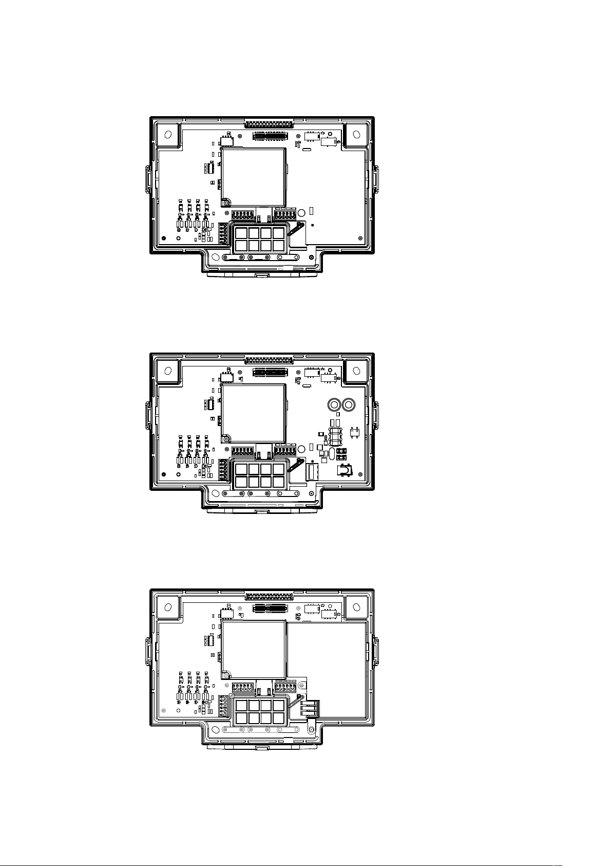
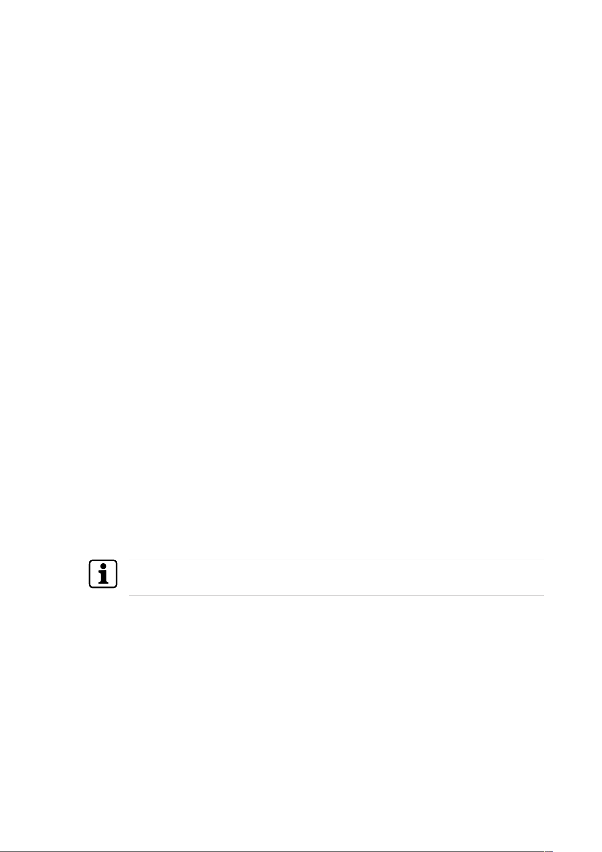
4.1.3.3 Docking station with BEX122 motherboard
The BEX122 motherboard is used in devices whose power supply takes place via PoE. The
BEX122 motherboard is not equipped with an additional power supply unit nor with a power
supply input.
4.1.3.4 Docking station with BEX121 motherboard
For power supply of the device, the BEX121 motherboard has a 24 V DC input with overvoltage protection and transient filter. This motherboard is used when the device is supplied
with 24 V DC.
Construction and functionTechnical Manual
4.1.3.5 Docking station with BEX120 motherboard
The BEX120 motherboard has a 100–240 V AC mains voltage input and an integrated limited
power source power supply unit (LPS). This motherboard is used when the device is supplied
with mains voltage.
2904043552 - 05/2017 Terminal 97 00DRAFT
Construction and function Technical Manual
4.1.3.6 Overview of the equipment
Equipment/Motherboard none BEX120 BEX121 BEX122
Power supply
PoE X X
24 V DC X
Mains voltage X
Interfaces
RS-232C interface X X X
Additional interface X X X
Inputs/Outputs
2 relay outputs X X X
4 digital inputs X X X
4.1.4 Interface assignment
COM port Assignment
COM1 Internal reader (integrated into terminal housing)
COM2 Internal reader (integrated into terminal housing)
COM3 Additional interface (docking station motherboard)
COM4 RS-232 for external reader (docking station motherboard)
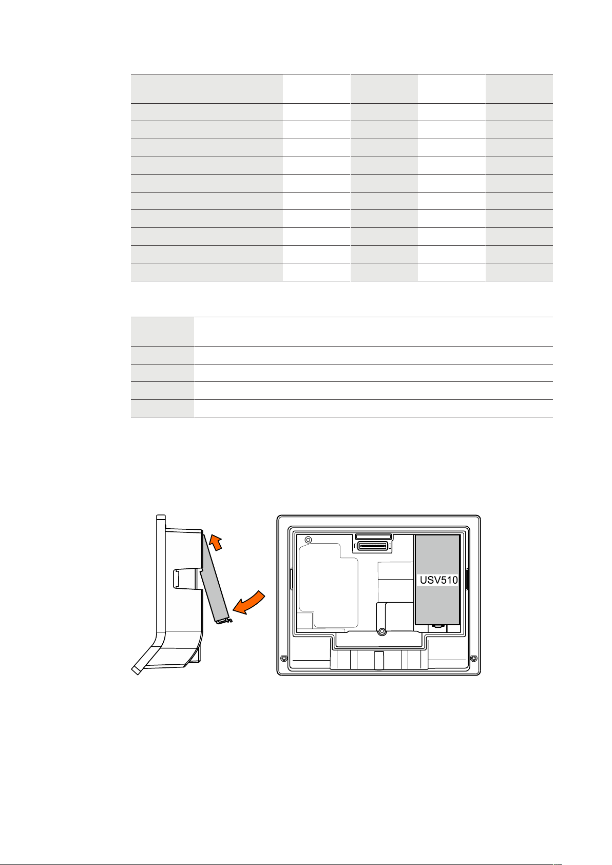
4.1.5 Uninterruptible power supply UPS510
The uninterruptible power supply UPS510 ensures operation in case of short-term power supply failure.
The UPS510 is snapped into place on the rear side of the terminal housing.
The UPS510 can be retrofitted or replaced at any time.
30 04043552 - 05/2017Terminal 97 00 DRAFT
 Loading...