

Dormakaba RCI 0162 Installation Manual
INSTALLATION
0162
Double Door Housing for
Surface Mounted Rim Strike
Instructions
1. Mark horizontal center line (CL) of existing device latch from active door to inactive door. Align center of Double Door Housing
(DDH) with horizontal centerline marked on inactive door and square it with edge of the inactive door. Maintain 3/16” minimum
gap between the exit device & strike face for proper functioning of exit device. See IS0162 for details.
2. Mark the mounting holes for the DDH on the inactive door using DDH as template.
3. Drill two 13/32” (10.5mm) holes through inactive door).
4. Mount DDH to inactive door using hardware as shown.
Note: Wire access hole is not provided, drill DDH as required.
5. Make wire connections from the power source to the appropriate wire harness supplied. Use the 12V harness for 12VDC,
12-24VAC or 11-16VAC. Use the 24V harness only for 24VDC.
6. Mount the electric strike with 1/4-20 UNC (Hole C) screws provided in the outer oval mounting holes (the
outer slots). Adjust electric strike horizontally until exit device latch fully engages with the door closed.
Note: Ensure a 1/16” [1.5mm] clearance between exit device latch and the electric strike keeper is maintained.
7. Tighten the two mounting screws and check operation. Adjust the horizontal position of electric strike as required.
8. Using the electric strike as a marking template, drill & tap for 1/4-20 UNC (Hole D). Using the 1/4-20 UNC screws provided
secure the electric strike through the locking holes.
Note: 0162 strike is not adjustable after installing these screws.
IMPORTANT: The fire and/or security ratings shown on the (F)0162 strike labels no longer apply with the use of the double door
housing.
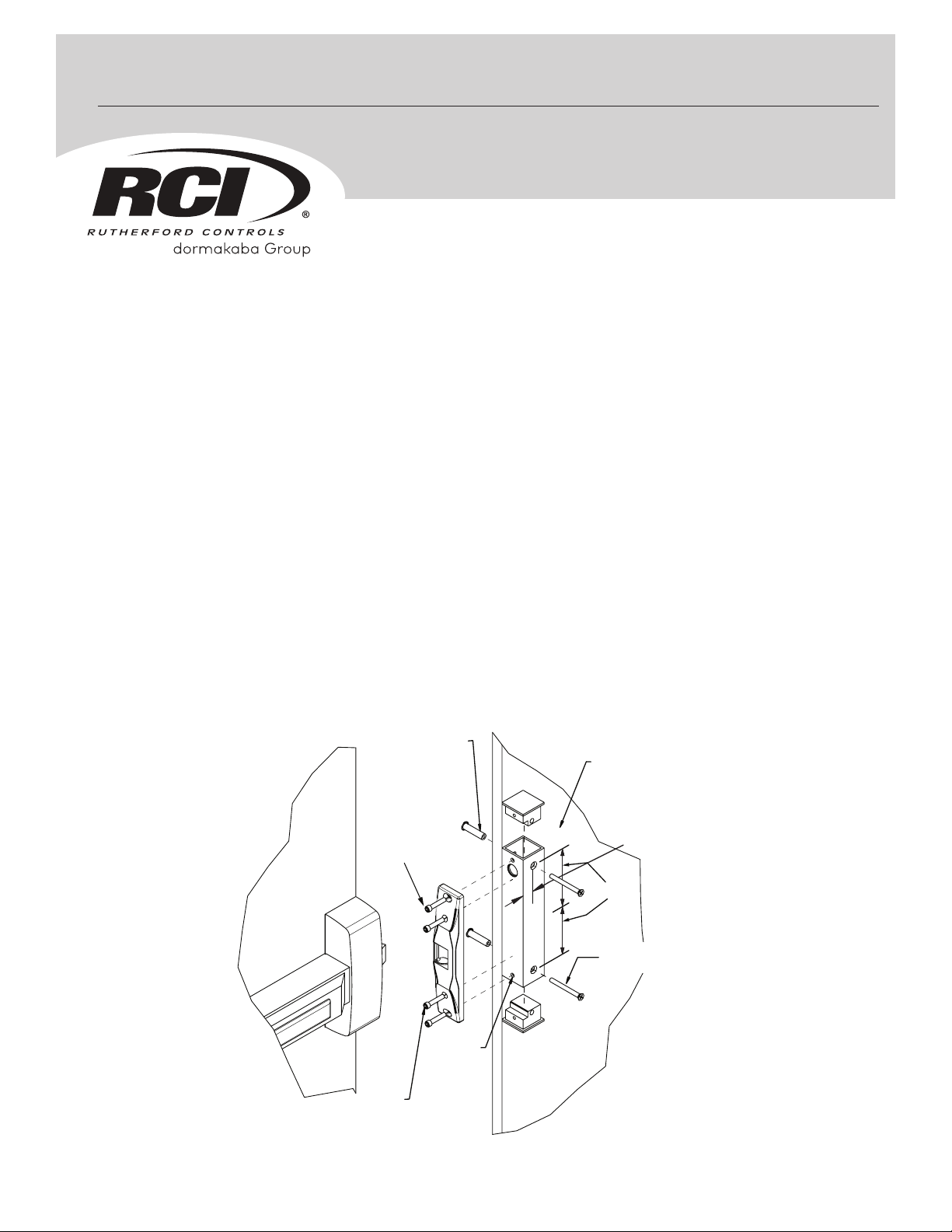
0162 Typical Double Door
Housing Assembly
IS0DDH
www.rutherfordcontrols.com • PHONE: 1.800.265.6630 • FAX: 1.800.482.9795 • E-MAIL: sales_rci@dormakaba.com
SEX NUT 1/4-20
WITH 13/32" HOLE
THROUGH (DOOR)
(2 PLACES)
HOLE C
1/4-20 X 1"
ADJUSTMENT
SCREW
HOLE C
1/4-20 X 1"
HOLE D
1/4-20 X 1"
LOCKDOWN
SCREW
(2 PLACES)
© 2018 dormakaba Canada Inc. | dormakaba Group
SCREW
INACTIVE
DOOR
7/8” (22.2mm)
3-3/4” (95mm)
C
L
1/4-20 X 2.5"
(2 PLACES)
0162 DOUBLE
DOOR HOUSING
PCN18003
R01-18TG
INSTALLATION
2
3
Double Door Housing
Instructions
1. Mark center line (CL) of existing device latch from active door to inactive door. Align center of Double Door Housing (DDH) with
horizontal centerline marked on inactive door and square it with edge of the inactive door. Maintain 3/16" minimum gap between
the exit device & strike face for proper functioning of exit device. See IS0161 for details.
2. Mark the mounting holes for the Double Door Housing (DDH) on the inactive door using DDH as template.
3. Drill two 13/32" (10.5mm) holes through inactive door.
4. Drill wire access hole into desired area of DDH. Pull two (2) wires through the access hole and connect to strike
(polarity is not critical).
5. Temporarily mount 0161 strike to DDH through the slotted holes (Hole C) using 1/4-20 UNC x 1" screws provided.
6. Mount DDH to inactive door using the two (2) 1/4-20 x 3” screws and 1/4-20 Sex Nuts supplied.
7. Adjust electric strike insert horizontally, if necessary, until Pullman Latch engages when door is closed. (See Fig. 3 on 0161
installation instructions if further horizontal insert adjustment is necessary).
8. Mark, drill and tap Hole D for 1/4-20 x 1” provided to secure the final location.
IMPORTANT: The security ratings shown on the 0161 strike labels no longer apply with the use of the double door housing.
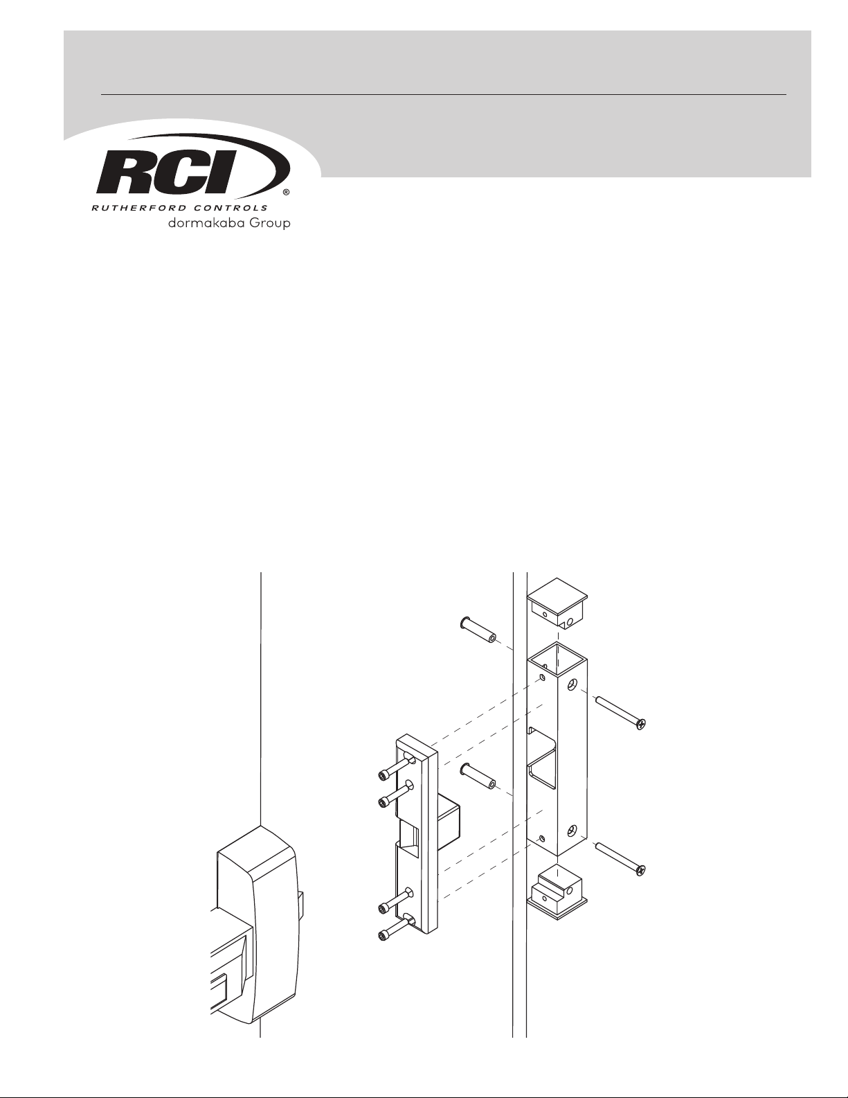
0161
0161 Typical Double
Door Housing Assembly
ACTIVE
DOOR
EDGE
TYPICAL SURFACE
EXIT DEVICE
HOLE C
ADJUSTMENT
SCREW
1/4-20 x 1”
HOLE D
LOCKDOWN
SCREW
1/4-20x1”
HOLE D
LOCKDOWN
SCREW
1/4-20 x 1”
HOLE C
ADJUSTMENT
SCREW
1/4-20 x 1”
SEX NUT
1/4-20
DRILL
13/32” HOLE
(2 PLACES)
INACTIVE
DOOR
C
L
0161 DOUBLE
DOOR HOUSING
SCREW
1/4-20 x 3”
www.rutherfordcontrols.com • PHONE: 1.800.265.6630 • FAX: 1.800.482.9795 • E-MAIL: sales_rci@dormakaba.com
© 2018 dormakaba Canada Inc. | dormakaba Group
 Loading...