

Page 1
ORACODE 660i WIRELESS LOCK
ACTIVATION / PROGRAMMING
For 660i Wireless Locks with Standard Gateway
For 660i Wireless Lock with Smart Controller
ORACODE SMART CONTROLLER INSTALLATION
1
1. SMART CONTROLLER POSITIONING
• Avoid placing the Smart Controller in close proximity
(< 5 feet / 2 m) to a WiFi device.
• Position the Smart Controller within 33 ft / 10 meters of
the lock.
• Avoid heavy obstruction between the Smart Controller and lock
(e.g., metallic or concrete wall or floor).
• Avoid placing the Smart Controller close to metallic objects (e.g.,
metallic table, refrigerator, filing cabinets, etc.).
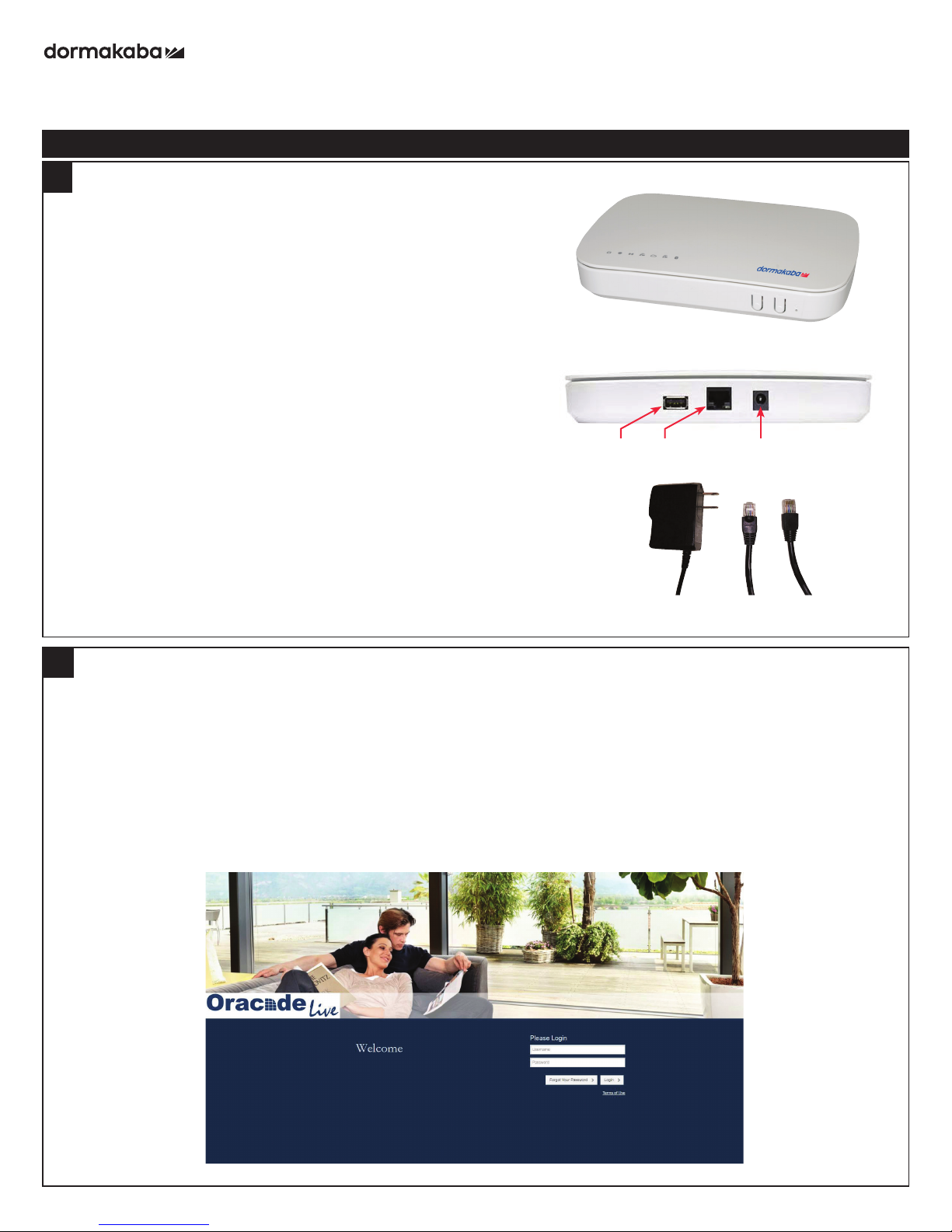
2. SMART CONTROLLER CONNECTION
• Connect the Smart Controller to the Internet modem/router
using the Ethernet Cable.
• Boot up the Smart Controller by connecting the Power Adapter.
• The Smart Controller will perform any necessary updates during
the boot-up process, and the green LEDs on the top of the
Smart Controller will come on (no specific order). The boot-up
process can take from 30 seconds to a few minutes.
• Wait until all green LEDs are on. This confirms the Smart
Controller has successfully performed all necessary updates and
is ready to connect to the Oracode Server
Note: The ZigBee LED may not illuminate during the initial
installation. This is normal in most situations. Proceed with Wireless
Lock Activation.
Smart Controller (Top)
Smart Controller (Back)
USB Ethernet Power
Power
Adaptor
Ethernet
Cable
2
WIRELESS LOCK ACTIVATION (PUT ON-LINE)
1. ACTIVATION CODE GENERATION
• Log on to your Oracode Live account (www.kabaecodewireless.com).
• Go to “Door Monitoring & Management” then to “Door Monitoring”.
• Within the “Door Monitoring” module, select the door to be activated from the door list, and click the ”Activate as
Wireless” button.
• Select the Time Zone where the controller and lock will be located. The Network Name will be populated
automatically, using the Door name as its basis. This can be edited if need be. Click “Save Changes”.
• When you click the “Save Changes” button, the Activation number will be provided.
• Use this number to complete the Activation Process in the following steps 2.2 (for Oracode Live) or 2.3 (for
BeHome247).
1 PK3646_07_18
Page 2
dormakaba Oracode 660i Wireless Lock Activation/Programming
2
WIRELESS LOCK ACTIVATION (Continued)
2. ACTIVATION PROCESS WITH ORACODE LIVE
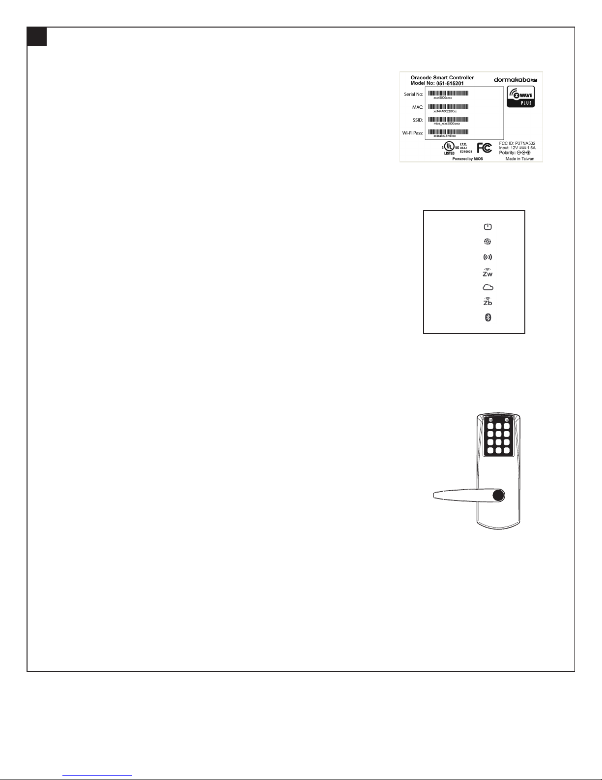
• Once the Activation number is provided, a new field will be presented where
the Smart Controller’s MAC address is to be entered.
• Enter the controller’s MAC address (located on Bottom Label), and then
click the “Enable Discovery Mode” button.
• The Smart Controller will be in ZigBee “Join” mode for 10 mins, and the
ZigBee LED on the Smart Controller will be blinking.
• On the lock keypad, press * # * # and enter the 8-digit Activation Code to
start the activation process.
• The lock’s green LED will blink once at the beginning of the activation
process (the activation process could last from a few secs to 2 mins).
• A green LED and a high-pitch beep indicates a successful connection to the
Oracode Server.
• A series of silent green LED blinks will follow. This is the lock programming
being received from the Oracode Server. Once there are no more silent
green LED blinks, the lock programming is complete.
• After a few moments, the Door Details page within Oracode Live for the
activated door will be displayed, confirming that the Activation Process
is complete.
• A red LED and a low-pitch beep at the end of the activation process
indicates a failure. In this case, consult Point 3.
2. ACTIVATION PROCESS WITH BEHOME247
• Log into your BeHome247 account (vr.behome247.com).
• Select the property where you are installing the Smart Controller, then click
the “Settings” tab.
• Notify BeHome247 of the controller’s Serial ID prior to the activation
process, so they can create the gateway on their server and assign it to the
account for activation.
• In the “BeHome247 Automation” area, enter the Smart Controller’s serial
number (located on Bottom Label) in the field labeled “Gateway Number”,
and click “Save.”
• Scroll down to the “KABA Lock System” area, enter the door’s name in the
field labeled “Door name”, check the “This property uses wireless I-locks”
box, and click “Save.”
• Check the “Show advanced controls” box, and click “Join” under “Zigbee
powered locks’.” The Smart Controller will be in ZigBee “Join” mode for
10 minutes.
• On the lock keypad, press * # * # and enter the 8-digit Activation Code to
start the activation process.
• The lock’s green LED will blink once at the beginning of the activation
process (the activation process could last from a few seconds to 2 minutes).
• A green LED and a high-pitched beep at the end of the activation process
indicates success.
• A series of silent green LED blinks will follow. This is the lock programming
being received from the Oracode Server. Once there are no more silent
green LED blinks, the lock programming is complete.
• You can now access the lock from the BeHome247 and Oracode
Live websites.
• A red LED and a low-pitched beep at the end of the activation process
indicates a failure. In this case, consult Point 3.
Smart Controller
(Bottom Label)
Smart Controller
(LED Panel)
1. Power
2. Internet
3. Wi-Fi
4. Z-wave
5. Service
6. ZigBee
7. Bluetooth
Oracode 660i (Front)
2 PK3646_07_18
Page 3

dormakaba Oracode 660i Wireless Lock Activation/Programming
3
ORACODE SMART CONTROLLER DIAGNOSTICS
1. LOCK TO SMART CONTROLLER “CONNECTION” STATUS
Entering # # # 2 on the lock keypad triggers a “Lock to Smart Controller” status test.
• A green LED and a high-pitched beep at the end of the test indicates the lock is connected to the
Smart Controller.
• A red LED and a low-pitched beep at the end of the test indicates the lock is not connected to the
Smart Controller.
2. WIRELESS LINK TEST
• This test requires the Smart Controller to be put in ZigBee “Join” mode (by enabling “Join” on the BeHome247
website) if the Lock is not already connected to the Gateway (see 3.1).
• Entering # # # 1 on the lock keypad triggers a “Lock to Gateway” wireless link test.
• The lock’s LEDs alternate green and red during the test, which may be very quick or last over 30 seconds
(depending on if the lock is already connected to the Smart Controller network or not).
• A green LED and a high-pitched beep at the end of the test indicates a good link quality (success).
• A red LED and a low-pitched beep at the end of the test indicates a bad link (fail).
• If the Wireless Link Test fails, improve the Smart Controller positioning (see 1.1) and re-execute the Wireless
Link Test.
3. SMART CONTROLLER RESET TO FACTORY DEFAULT
NOTE: You will need to get a new Activation Code from the Oracode Live web site to re-activate the lock (see
Point 2) after you perform a Reset to Factory Default of the
Smart Controller.
METHOD 1
• Use a paperclip or pencil to press the “Reset” button (on the
front of the Smart Controller) six times within six seconds. The
Smart Controller will be reset to factory default.
METHOD 2
• Log into your BeHome247 account (vr.behome247.com).
• Select the property where the Smart Controller is installed,
then click the “Settings” tab.
• Scroll down to the ‘KABA Lock System’ area, check the “Show
advanced controls” box, and click “Reset.” The Smart Controller
will be reset to factory default.
Smart Controller (Front)
Select Sync Reset
CONNECT ZWAVE DEVICES
4
1. ENABLE ZWAVE JOIN MODE
• Press the “Select” button on the front of the controller until the LED by the Z-Wave icon is
blinking (approx. 3x).
• Press the “Sync” Button. The Smart Controller will be in Z-Wave “Join” mode for
10 minutes.
2. JOIN Z-WAVE DEVICES
• Follow the instructions for the Z-Wave device to enable Z-Wave join/search mode.
• The Z-Wave device will indicate if it was successfully added to the Z-Wave network. This
process can take from a few seconds to a few minutes.
• The Z-Wave device should be accessible in the BeHome247 website under the
“Settings” tab.
Smart Controller
(LED Panel)
1. Power
2. Internet
3. Wi-Fi
4. Z-wave
5. Service
6. ZigBee
7. Bluetooth
3 PK3646_07_18
Page 4

dormakaba Oracode 660i Wireless Lock Activation/Programming
5
STANDARD ORACODE GATEWAY INSTALLATION
1. GATEWAY POSITIONING
• Avoid placing Gateways in close proximity (< 5 feet / 2 m) to a
WiFi device.
• Position the Gateway within 33 ft / 10 meters of the lock.
• Avoid heavy obstruction between gateway and lock (e.g., metallic,
concrete wall or floor).
• Avoid placing Gateway close to metallic objects (e.g., metallic table,
refrigerator, filing cabinets, etc.).
2. GATEWAY CONNECTION
• Connect the Gateway to the Internet modem/router using the
Ethernet Cable.
• Power-up the Gateway with the Power Supply.
• On the opposite end of the Gateway relative to power/Ethernet cable,
the left most LED (green) provides status of the Gateway to Oracode
Server connection (Please see GATEWAY LED STATUS TABLE).
• Wait until you get a slow blinking green LED (about 20 seconds). This
confirms the Gateway connected successfully to the Oracode Server.
• If green LED is off, it means the connection to the Oracode Server
failed. Verify the Ethernet connections and that the Internet access is
operational. Repeat step 2.
Standard
Oracode Gateway
Power supplyEthernet Cable
6
WIRELESS LOCK ACTIVATION (PUT ON-LINE)
1. ACTIVATION CODE GENERATION
• Generate an Activation Code for the lock on the Oracode Live website.
(www.kabaecodewireless.com).
2. ACTIVATION PROCESS
• Use a pencil or paperclip to press the “Connect Button” on the Gateway.
The Gateway will stay in “Connect Mode” for 15 minutes; the green and
red LEDs will blink in unison while in “Connect Mode”.
• On the lock keypad, press * # * # and enter the 8-digit Activation Code to
start the activation process.
• The lock’s green LED will blink once at the beginning of the Activation
process (the activation process could last from a few seconds up to
2 minutes).
• A green LED and a high-pitched beep at the end of the Activation
process indicates success. You can now access this lock from the Oracode
Live website.
• A red LED and a low-pitched beep at the end of the activation process
indicates a failure. If this is the case consult point 7.
Green LED
Red LED
Connect Button
4 PK3646_07_18
Page 5

dormakaba Oracode 660i Wireless Lock Activation/Programming
STANDARD ORACODE GATEWAY DIAGNOSTICS
7
1. LOCK TO ORACODE GATEWAY “CONNECTION” STATUS
• Entering # # # 2 on the lock keypad triggers a “Lock to Gateway” status test.
• A green LED and a high-pitched beep at the end of the test indicates the lock is connected to the Gateway.
• A red LED and a low-pitched beep at the end of the test indicates the lock is not connected to the Gateway.
2. WIRELESS LINK TEST
• This test requires the Gateway to be put in “Connect Mode” (by pressing the “Connect button” on the Gateway) if
the lock is not already connected to the Gateway (see 3.1).
• Entering # # # 1 on the lock keypad triggers a “Lock to Gateway” wireless link test.
• The lock’s LEDs alternate green and red during the test which may be very quick or last over 30 seconds
(depending on if the lock is already connected to the Gateway network or not).
• A green LED and a high-pitched beep at the end of the test indicates a good link quality (success).
• A red LED and a low-pitched beep at the end of the test indicates a bad link (fail).
• If the Wireless Link Test fails, improve Gateway positioning (see 1.1) and re-execute the Wireless Link Test.
3. ORACODE GATEWAY RESET TO FACTORY DEFAULT
NOTE: You will need to get a new Activation Code from the Oracode Live web site to re-activate the lock (see Point
2) after you perform a Reset to Factory Default of the Gateway.
• Unplug the Power Supply from the Gateway for more than 5 seconds.
• Press and hold the “Connect Button” while you re-apply power to the Gateway.
• Hold the “Connect Button” until the green and red LEDs start blinking rapidly.
• Release the “Connect Button” and wait until the green and red LEDs turn off.
• Again, unplug the Power Supply from the Gateway for more than 5 secs and go back to Point 1.1.
4. ORACODE GATEWAY LED STATUS TABLE
GREEN LED RED LED GAT EWAY S TATE
ON ON Power On (will be in this state for about 15 seconds).
OFF OFF No Server connectivity. No ZigBee network.
FAST BLINK FAST BLINK Red/Green alternates. Waiting for DHCP address assignment or server DNS
resolution.
FAST BLINK FAST BLINK LEDs blink in unison. Reset to Factory in progress. This only lasts a few seconds
during reset.
OFF ON* No eCode Server (Oracode Live) connection. * Could be fast, slow, or solid LED.
SLOW BLINK OFF Gateway ready. No ZigBee network.
SLOW BLINK ON Gateway ready. ZigBee network up. This is the normal Gateway operating state.
SLOW BLINK SLOW BLINK LEDs blink in unison. ZigBee network up. Connect Mode on.
TECHNICAL SUPPORT HOTLINE
Call 1-888-217-5654 or 1-514-340-9025 (International)
Full service from 8:30 am to 7:00 pm Eastern Time
Emergencies 24/7
Email: techsupport.lgs.ca@dormakaba.com
www.dormakaba.com/us-en/support
5 PK3646_07_18
 Loading...