

Page 1
INSTALLATION AND OPERATING INSTRUCTIONS
Electronic Gate Lock GL10
Page 2

Page
1
CONTENTS
• DESCRIPTION
• PRODUCT UNBOXED
• PRE - INSTALLATION ASSESMENT
o Mechanical
o Electrical
• INSTALLATION
o Mark the lock position
o Drill the lock mounting holes
o Secure the lock in position
o Mark the strikes position
o Drill the strikes mounting holes
o Secure the strike in position
o Wire the lock
o Cover the lock
• WIRING
• OPERATING CONFIGURATION
o Fail State
o Auto re-lock
o Timed re-lock
o Diagnostic mode
• OPERATION
o Auto re-lock ON
o Auto re-lock OFF
o General
o Alarms
• SPECIFICATIONS
• DIMENSIONS
o Lock
o Strike
• MAINTENANCE
• WARRANTY
• UPGRADE
2
2
2
2
3
4
4
4
4
4
5
5
5
5
6
6
7
7
7
7
7
8
8
9
9
10
10
10
11
11
11
11
Page 3
Page
2
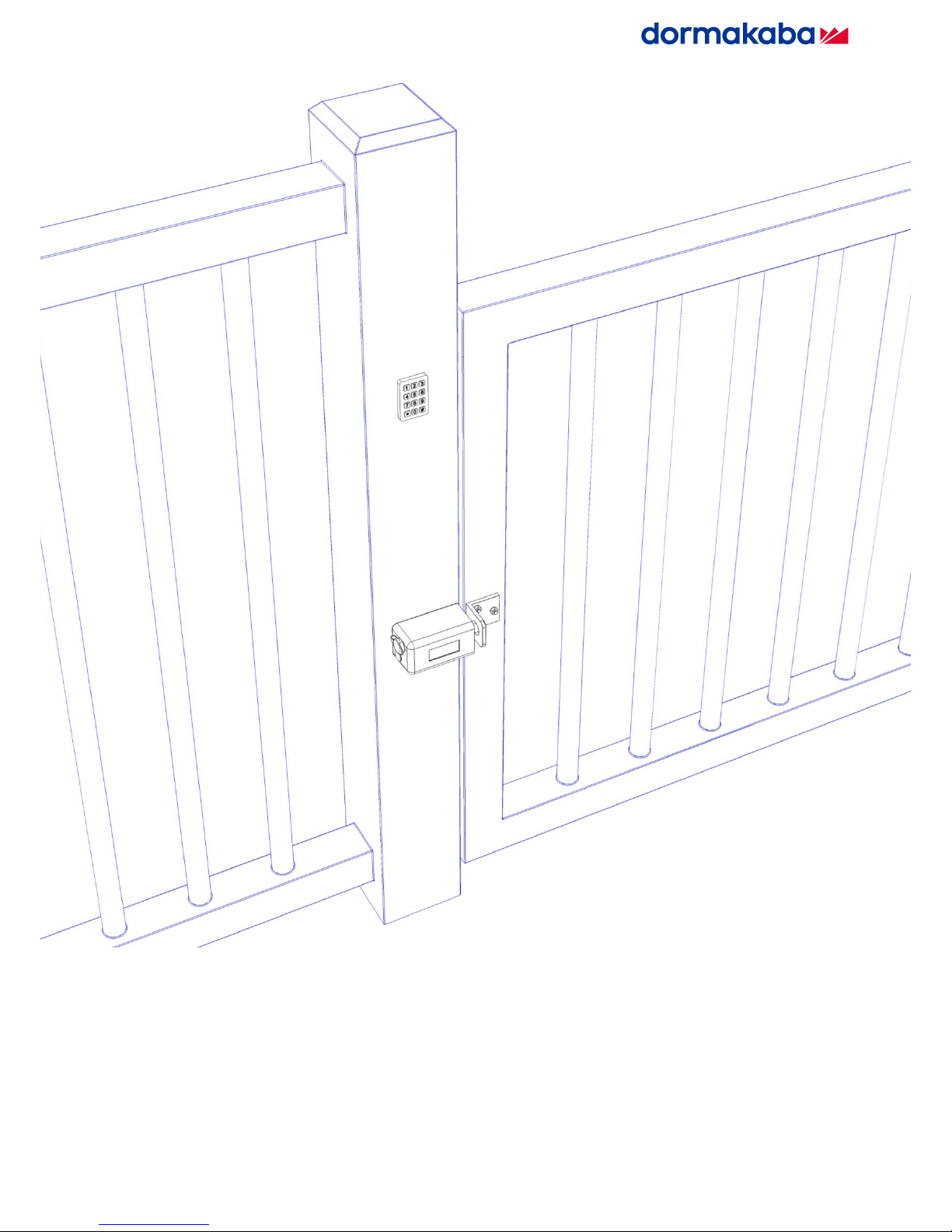
1. DESCRIPTION
The GL10 is a low voltage motor driven lock suited for securing vehicle and pedestrian gates. It is supplied with a
matching strike plate and can be installed externally or internally in a horizontal or vertical position. It is designed for
use on single or double gates and can be mounted to suit hinged or sliding applications. A solid 18mm diameter
stainless steel bolt pin ensures the highest strength while a bolt pin extension of 35mm offers flexible installation.
Integrated electronics provide complete control over the lock and offer an array of features;
▪ Multi–voltage input (12-24VDC)
▪ Multiple locking / unlocking attempts to correct miss-aligned gates
▪ Selectable automatic locking when the gate closes
▪ Fail safe / Fail secure user selection with a single switch
▪ Gate position monitoring
▪ Bolt locked and Bolt unlocked monitors
The lock incorporates a keyed manual override and wiring can be run securely through the locks base or externally
through a 20mm wiring gland.
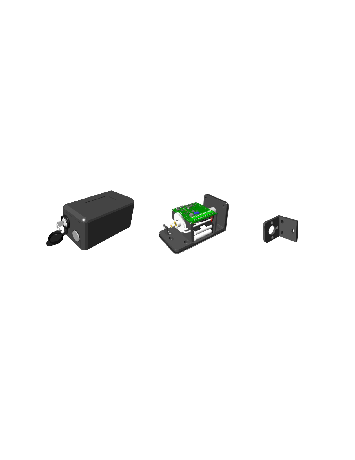
2. PRODUCT UNBOXED
Lock Cover with two keys Lock Strike
Also included in the box are 4 x AA batteries. Because of the various fitting locations of the GL10, no mounting
bolts are supplied. The mounting holes in the lock and strike are 8.5mm slotted holes so accept M8 size bolts.
3. PRE - INSTALLATION ASSESMENT
3.1 Mechanical
Before the lock can be installed, consider its location and orientation. The GL10 can be mounted horizontally or
downwards vertically but it cannot be mounted vertically locking upwards. Mounting it in this way can allow water
to penetrate that lock and will void the warranty. Depending on the chosen mounting position, spacers or packers
may need to be made and used.
When positioning the strike, it is important to achieve a reasonable level of alignment with the bolt pin as to ensure
correct locking and operation. The hole in the strike is of significantly larger diameter than that of the lock pin, however
installing the strike so the lock pin goes into the hole centrally is best as it will allow for movement of the gate over
time.
There are three magnets in the strike which offers the flexibility of mounting options and with the symmetrical design
of the lock, the strike can approach from either the right, left or bottom face of the lock.
Page 4
Page
3
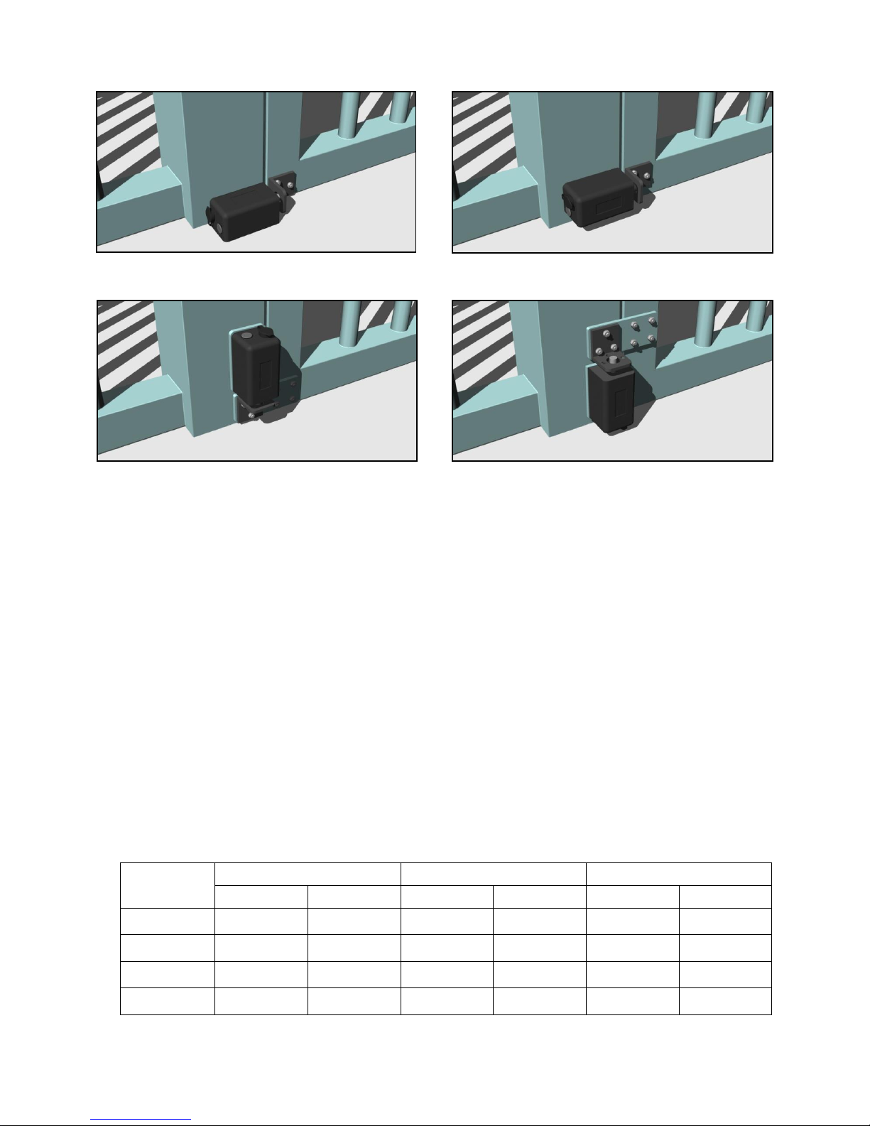
Lock mounted to the ground. Lock mounted to the gate frame horizontally.
Lock mounted to the gate frame vertically down. DO NOT mount the lock vertically up.
3.2 Electrical
After the positions of the lock and strike are determined, establish where to run the wires and also decide on what
feedback is required from the lock. There are a total of eleven available connections on the GL10; three are
compulsory and eight are optional. The three essential connections are; Positive (+), Negative (-) and Control (CL).
There need to be wires run from the power source and control switch to the lock.
The eight optional connections all provide feedback about the locks state; Gate Position, Bolt Locked Position and
Bolt Unlocked Position. If desired, wires can be run from these connections to integrate into access control or alarm
systems to provide full monitoring.
Once the number of wires and their destination is determined, it needs to be decided how the wires will enter the
lock. They can either come in through a 20mm weather proof wiring gland at the rear of the lock (not supplied), or
through a hole under the locks base which will ensure the wires can be hidden.
Finally, the correct wire gauge needs to be chosen to ensure a minimal voltage drop. The correct wire gauge is
important when connecting the power wires (+ and -) to the lock as voltage drop across these wires can limit the
locks operation and prematurely deplete the batteries. For all the remaining connections, a lower gauge wire can be
used as these are only signal wires.
The following chart shows the appropriate wire gauge for a range of distances between the lock and power supply.
Distance (m)
AWG Size
Metric Size (mm2)
Wire Diameter (mm)
12VDC
24VDC
12VDC
24VDC
12VDC
24VDC
5
24
24
0.21
0.21
0.51
0.51
20
22
24
0.33
0.21
0.65
0.51
50
18
20
0.83
0.52
1.02
0.82
100
NA
16
NA
1.31
NA
1.29
Page 5

Page
4
4. INSTALLATION
A typical vehicle gate lock installation is described. The lock is being mounted to the fence post while the strike will
be mounted to the gate on the left of the lock. Coach bolts would be used to secure the lock and strike.
4.1 Mark the lock position
Locate the lock in the desired position and
using a pen / pencil mark the three mounting
hole locations through the lock base.
4.2 Drill the lock mounting holes
Use a M8 drill bit to drill the three mounting
holes in the fence post.
Check on the preferred
wiring method and if running
the wires through the base
is desired, also mark and
drill the wire hole now.
See section 5 - Wiring.
4.3 Secure the lock in position
Push the bolts through the fence post and
position the lock over the protruding bolt ends.
Place nuts on the three bolts and tighten
them to secure the lock to the post.
4.4 Mark the strikes position
Locate the strike in the correct position and
using a pen / pencil mark the three mounting
hole locations through the strike.
Page 6

Page
5
4.5 Drill the strikes mounting holes
Use a M8 drill bit to drill the three mounting
holes in the gate.
4.6 Secure the strike in position
Push the bolts through the gate post and
position the strike over the protruding bolt ends.
Place nuts on the three bolts and tighten
them to secure the strike to the gate.
4.7 Wire the lock
Using a screwdriver and following the
connection guide on the printed circuit board,
connect the required wires to the lock.
Detailed wiring information can
be found in section 5 - Wiring
4.8 Cover the lock
Position the cover over the lock and push it
down and forward. Use the keyed cam lock
in the back of the cover to secure it in place.
Page 7

Page
6
Wires run through a gland in the rear off the lock.
Wires run out of the hole in the base of the lock.
5. WIRING
Connect the GL10 as per the chart below. The three power connections are vital for the operation of the lock whilst
the eight monitor connections are outputs supplied to offer feedback if desired.
+
Power
Positive connection to DC power supply (12 – 24V)
-
Negative connection to DC power supply (12 – 24V)
CL
Switched positive control input
NC
Bolt Position Switch - Unlocked
Normally closed contact of the bolt position unlocked monitor
NO
Normally open contact of the bolt position unlocked monitor
C
Common contact of the bolt position unlocked monitor
NC
Bolt Position Switch - Locked
Normally closed contact of the bolt position locked monitor
NO
Normally open contact of the bolt position locked monitor
C
Common contact of the bolt position locked monitor
NO
Door Position Switch
Normally open contact of the gate position monitor
C
Common contact of the gate position monitor
There are two options available when running wires into the GL10; they can be brought in through a 20mm wiring
gland (not supplied) in the rear of the cover, or run discreetly through the hole in the locks base.
Running wires out of the lock via the hole in base ensures a more weather proof and secure installation as the wires
can be concealed. If the preferred option is to use a 20mm wiring gland, a hole is available in the rear of the cover to
achieve this. This hole is covered by a factory fitted blank held in place by an M3 screw that can be removed.
6. OPERATING CONFIGURATION
The operating configuration of the GL10 controls how the lock will function and there are several settings available.
There are four dip switches on the printed circuit board with three being used to configure the lock and the fourth for
diagnostic purposes. The dip switches are located on the top of the printed circuit board and can be set as per the
following table.
Page 8

Page
7
1
ON
Fail Safe operation
With batteries fitted, in the event of a power failure the GL10 will unlock
OFF
Fail Secure operation
With batteries fitted, in the event of a power failure the GL10 will lock
2
ON
Auto re-lock on
The GL10 will automatically lock when the gate closes
OFF
Auto re-lock off
The GL10 only locks when the user desires
3
ON
Timed re-lock on
The GL10 will re-lock after one minute if an unlock signal is given and
the gate remains closed - Auto re-lock must also be enabled
OFF
Timed relock off
The GL10 will never re-lock if an unlock signal is given and the gate
remains closed
4
ON
Diagnostic mode on
The GL10 goes into a service mode to output information*
OFF
Diagnostic mode off
The GL10 operates as normal
*Should only be activated in the event of a failure.
6.1 Fail State – Switch 1
The fail state of the GL10 is determined by the selection of switch 1; however there is an additional state that can be
used if desired. With no batteries installed the lock will default to Fail Maintained. In this configuration and in the
event of a power failure, the lock will stay in the position it was in before the power was removed. With the batteries
fitted however, selecting Fail Safe or Fail Secure ensures that the GL10 will move to that selected state if the power
does fail.
6.2 Auto re-lock – Switch 2
It is recommended that Auto re-lock be ON in most installations. The ability of the GL10 to sense the gates position
and automatically lock when it is closed is paramount to increasing security as it eliminates the need for the user to
do so. If Auto re-lock is not selected the GL10 operates on a toggle method. In this configuration an activation of the
control signal will cause the GL10 to unlock and a second activation will cause it to lock, assuming the strike is in
place.
6.3 Timed re-lock – Switch 3
Timed re-lock can only be enabled when Auto re-lock has been selected and it is recommended to be ON in most
installations. For increased security the GL10 has the ability to automatically lock itself after a timed period in the
event of a user failing to do so. If an unlock signal is given to the lock but the gate is not opened the GL10 can
automatically lock itself again after one minute. This ensures that a gate can not be left unsecured if it has been
unlocked but not opened.
6.4 Diagnostic mode – Switch 4
By default the Diagnostic mode should be set to OFF. If the GL10 fails then the Diagnostic mode can be activated
and information extracted from it to help determine what has caused the fault. This information needs to be interpreted
by a registered distributor or the original manufacturer.
7. OPERATION
The operating scenarios detailed below stay the same regardless of whether the GL10 is configured in a Fail Safe,
Fail Secure or Fail Maintained state. The state of the lock is only relevant in the event of a total power failure. Both
scenarios assume that the control signal is open at the start of the operation sequence as a maintained connection
will cause the lock to stay unlocked indefinitely.
Page 9

Page
8
7.1 Auto re-lock ON
With Auto re-lock ON selected,
the momentary connection of
CL to + acts as the unlock signal.
Closing the gate so the strike
aligns with the lock and the
magnet activates the internal
switch, acts as the lock signal.
7.2 Auto re-lock OFF
With Auto re-lock OFF selected,
the momentary connection of
CL to + acts as both the lock
and unlock signals for the GL10.
YES
NO
YES
NO
YES
NO
YES
NO
GATE CLOSES
HAS THE
GATE OPENED?
UNLOCK SIGNAL
HAS THE BOLT PIN
RETRACTED AFTER
3 ATTEMPTS?
GL10 IN STANDBY
GATE IS UNLOCKED
GL10 IN STANDBY
GATE IS LOCKED
HAS THE BOLT PIN
EXTENDED AFTER
3 ATTEMPTS?
HAS A LOCK
SIGNAL BEEN SENT
YES
YES
NO
NO
YES
NO
YES
YES
NO
GATE CLOSES
INTERNAL
ALARM SOUNDS
HAS THE BOLT PIN
EXTENDED AFTER
3 ATTEMPTS?
IS THE
GATE OPEN?
HAS THE GATE
OPENED WITHIN
1 MINUTE?
UNLOCK SIGNAL
HAS THE BOLT PIN
RETRACTED AFTER
3 ATTEMPTS?
GL10 IN STANDBY
GATE IS UNLOCKED
GL10 IN STANDBY
GATE IS LOCKED
IS THE TIMED
RE-LOCK ON?
INTERNAL
ALARM SOUNDS
INTERNAL
ALARM SOUNDS
INTERNAL
ALARM SOUNDS
Page 10

Page
9
Clockwise turning of the large
gear will retract the bolt pin.
Anti-clockwise turning of the large
gear will extend the bolt pin.
The GL10 features multiple locking / unlocking to allow for misaligned gates or unforeseen problems. If the bolt pin
meets an obstruction as it is trying to secure the gate, it stops and withdraws before attempting to lock again. It has
a total of three attempts to secure the gate after which time it will sound an alarm. The same function is present when
the GL10 unlocks.
7.3 General
If the batteries are fitted and the power is removed to the GL10 at any time during its operation, the lock will revert to
its pre-selected state of either unlocked or locked. The GL10 has been designed to operate with high quality
disposable alkaline batteries and may not work correctly with alternatives. Should the batteries become flat the
lock will sound an alarm to indicate a battery change is required.
If the batteries are not replaced once they have become depleted, the GL10 will automatically revert to the Fail
Maintained state; i.e. in the event of a power failure the lock will stay in the position it was in before the power was
removed.
The three monitors can be used to provide door and bolt position information regardless of the locks configuration.
Manual operation of the GL10 is available by removing the cover to allow access to the lock mechanism. The supplied
key can be used to open and remove the cover and once access is available a screwdriver can be inserted into the
centre of the large gear and turned to move the bolt pin in or out.
7.4 Alarms
To offer instant feedback about the locks state, the GL10 has an on board beeper which sounds at various times.
The table below details the different alarms expected from the GL10.
Locked confirm
1 Short beep
Unlocked confirm
2 Short beeps
Failure to lock / unlock
5 Long beeps
Battery replacement
5 Short beeps sounded 5 seconds after a lock activation and repeated every
10 minutes until the batteries are replaced
Diagnostic
Various beeps – used for service
Page 11

Page
10
If the Failure to lock / unlock alarm has been sounded it is important that the cause of the obstruction is investigated
immediately. As the alarm sounds to indicate the bolt pin has not completed its correct action, it is possible that the
gate is unsecured so the security of the building is at risk. Any obstruction that is identified needs to be cleared so
the lock is free to operate as normal.
8. SPECIFICATIONS
Bolt Pin
Stainless Steel, ø18mm, 35mm stroke
Lock
Die Cast Aluminium, 152mm x 88mm x 78mm
Strike
Die Cast Aluminium, 75mm x 75mm x 70mm
Holding Force
3000Kg (30000N)
Power Supply
12 – 24VDC ±15%
Durability
1,000,000 Operations
Current Usage
Holding
12V < 15mA
Operation
12V < 300mA
Stall
12V < 2A
24V < 15mA
24V < 200mA
24V < 1A
Batteries
4 x AA 1.5VDC Alkaline
Monitor Switches
Bolt position – 60VDC, 0.2A
Gate position – 100VDC, 0.5A
Environment
IP65
9. DIMENSIONS
The dimensions shown are approximate and are subject to change without prior notice.
9.1 Lock
Page 12

Page
11
9.2 Strike
10. MAINTENANCE
The GL10 has been treated with grease and applying any other type of lubricant may void the warranty. With the
cover removed it is important to take care when replacing the batteries, selecting the configuration or manually
overriding the mechanism.
11. WARRANTY
The GL10 is covered with a manufacturer’s 12 month warranty against faulty or malfunctioning parts, components or
product. At the manufacturer’s discretion, either a replacement lock or affected part will be supplied to remedy the
fault. Mistreatment or ill-use of the lock may void the warranty. dormakaba will not be liable for any direct, indirect,
incidental or consequential loss or damage in any way related to this product.
12. UPGRADE
dormakaba reserves the right to upgrade or change this product without prior notice.
For more information visit:
www.dormakaba.com.au
www.dormakaba.co.nz
MP001159 Version 3.0
 Loading...