

Page 1
dormakaba digital cylinder
1220013692 - 11/2017
EN
Technical Manual
Page 2

dormakaba Schweiz AG
Mühlebühlstrasse 23
8620 Wetzikon
Switzerland
T: +41 (0)44 931 61 11
www.dormakaba.com
dormakaba Austria GmbH
Ulrich-Bremi-Straße 2
3130 Herzogenburg
Austria
T: +43 (0)2782 808 0
www.dormakaba.com
Copyright © dormakaba 2017
All rights reserved.
No part of this document may be reproduced or used in any form or by any means without prior written permission of dormakaba Schweiz AG.
All names and logos of third-party products and services are the property of their respective owners.
Subject to technical changes.
1220013692 - 11/2017
Page 3

Table of contentsTechnical Manual
31220013692 - 11/2017 dormakaba digital cylinder
Table of contents
1 About this document 5
1.1 Validity 5
1.2 Target group 5
1.3 Contents and purpose 5
1.4 Supplementary documentation 6
1.5 Digital cylinder abbreviations 6
1.6 Hazard categories 6
1.7 Notes 7
1.8 Symbols 7
2 Basic safety instructions 8
2.1 Proper use 8
2.2 Product changes 8
2.3 Use in emergency exit or panic door locks 8
2.4 Areas of use 9
2.5 ESD protective measures 10
2.6 Handling of lithium batteries 10
3 Product description 11
3.1 Overview 11
3.1.1 Structure 11
3.2 Scope of delivery 11
3.2.1 Also for dual digital cylinder 11
3.3 Accessories 11
3.4 Technical data 12
3.4.1 Dimensions 13
3.5 Conformity 16
4 Installation 17
4.1 Requirements 17
4.1.1 Door components 17
4.1.2 Tools required 18
4.2 Installation versions 19
4.2.1 Installation version A 20
4.2.2 Installation version B 22
4.2.3 Function check on anti-panic digital cylinder 24
5 Programming 25
5.1 Initial programming of MRD components 25
5.2 Initial programming of LEGIC® and MIFARE components 25
5.3 Master media 25
5.4 User media 25
5.5 Program structures 26
5.6 A/B and B structures 26
5.7 Programming user media with B masters 27
5.8 Deleting individual user media 28
5.9 Deleting individual B masters 29
5.10 Deleting all user media 30
5.11 INI reset with master media for whitelist and CardLink™ 31
6 Operation 33
6.1 Operating the digital cylinder 33
6.2 Opening with user media 33
Page 4

Table of contents Technical Manual
4 1220013692 - 11/2017dormakaba digital cylinder
7 Maintenance 34
7.1 Maintenance table 34
7.2 Maintenance of escape doors 34
7.3 Cleaning 35
8 Service 36
8.1 Serial numbers 36
8.2 Replacing the battery 36
8.3 Replace e-module 38
8.4 Disassembling the inner door knob 39
8.4.1 'Click' door knob 39
8.4.2 'Small' inner knob 39
8.5 Configuration and traceback 39
8.6 Reset (INI reset) 39
8.6.1 Reset with master media 40
8.6.2 Reset using programmer 1460 40
8.6.3 Reset using tweezers 40
8.7 Emergency power supply 40
9 Troubleshooting 41
9.1 Error analysis 41
9.2 Error analysis for battery life 43
10 Appendix 44
10.1 Summary of various factors influencing the battery operation 44
10.2 Recommendations for battery operation 44
Page 5

About this documentTechnical Manual
51220013692 - 11/2017 dormakaba digital cylinder
1 About this document
This section contains information for the proper use of this document.
1.1 Validity
This document describes the product:
Product designation: dormakaba digital cylinder
Types: 143X dormakaba Digital cylinder with Euro profile (17mm)
153X dormakaba Digital cylinder with round profile (22mm)
Article numbers and variants:
Euro profile cylinder 1435 Standard
1434 Half
1437 Anti-panic
1439 Dual
1431 Asymmetrical
1433 Half with turning range
Round profile cylinder 1535 Standard
1534 Half
1537 Anti-panic
1539 Dual
1531 Asymmetrical
1533 Half with turning range
All versions are available with wireless functionality.
With the exception of the asymmetrical version, all components
are available as ‘protected’ variants (with high anti-drill protection).
1.2 Target group
This document is intended for specialist personnel only.
The descriptions are tailored to specialist personnel trained by the manufacturer. The descrip-
tions are no replacement for product training.
Service personnel are persons who have the appropriate technical training and experience re-
quired for them to be aware of the risks that could arise for themselves or others when carrying out these activities and to minimise these risks for themselves and others. It is the responsibility of the service personnel to ensure that the conditions stated by the manufacturer
and the applicable regulations and standards are complied with when carrying out these
activities.
1.3 Contents and purpose
The contents of these instructions are limited to the installation, operation, maintenance and
servicing of the product.
Page 6
About this document Technical Manual
6 1220013692 - 11/2017dormakaba digital cylinder
1.4 Supplementary documentation
The following documents are available from the sales partners:
• Programmer 1460 technical manual
• Operating manual for programmer 1364
• Wireless operation: Wireless planning guideline
• Documentation for the system software used
1.5 Digital cylinder abbreviations
Short designation Product designation
Digital cylinder dormakaba digital cylinder
Programmer Programmer 1460
1.6 Hazard categories
Instructions with information on what to do and not to do to prevent injury and material
damage are denoted specially.
Please follow all hazard instructions. These are intended to help prevent accidents and prevent damage.
These instructions are divided into the following categories:
DANGER
High risk
Denotes an immediate danger that could lead to serious injury or death.
WARNING
Medium risk
Denotes a potentially dangerous situation that could lead to serious injury or death.
CAUTION
Low risk
Denotes a potentially dangerous situation that could lead to minor injury.
NOTICE
Important information on the correct use of the product.
Failure to comply with these instructions could lead to malfunctions. The product and/or objects in the local vicinity could be damaged.
Page 7
About this documentTechnical Manual
71220013692 - 11/2017 dormakaba digital cylinder
1.7 Notes
Information is denoted by this symbol.
Tips on using the product are useful pieces of information.
They help to make best use of the product and its functions.
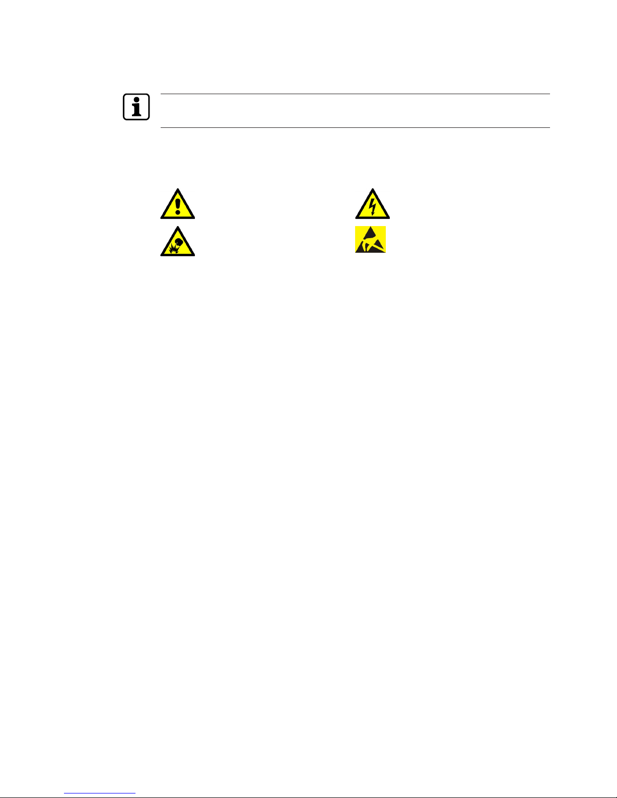
1.8 Symbols
Symbols with the following meanings are used for hazards (depending on hazard source.)
General hazard Hazard from electric shock
Risk of explosion Risk to electronic components from
electrostatic discharge
Page 8
Basic safety instructions Technical Manual
8 1220013692 - 11/2017dormakaba digital cylinder
2 Basic safety instructions
This product has been built to state-of-the-art standards and in line with established safety
regulations. However, hazards for persons and property may arise when handling the product.
Read and observe the following safety instructions before using the product.
2.1 Proper use
This product has been designed exclusively for use as set out in the chapter Product Description. Any other use will be deemed improper use. The manufacturer accepts no liability for any
resulting damage. The user/operator bears sole responsibility for the risk.
2.2 Product changes
NOTICE
No changes should be made to the product, unless in accordance with changes described in
the instructions.
2.3 Use in emergency exit or panic door locks
WARNING
Risk of personal injury or death.
• Improper use or incorrectly installed digital cylinders can lead to emergency exit locks or
panic door locks and doors not opening.
• The use of a digital cylinder must be checked carefully before using it in locks with a panic
function.
• Before installing the digital cylinder in an escape door, a check must be carried out to ensure that the function of the lever handle or the panic push bar is not obstructed by the
inside knob.
• The use of a digital cylinder in emergency exit locks in accordance with EN179 or in panic
door locks in accordance with EN1125 is documented in the lock manufacturers' performance declarations. If the digital cylinder is not listed in the performance declarations or
certificates from the lock manufacturer or the lock does not comply with these standards,
an EC conformity inspection of the lock, digital cylinder, fitting and assembly accessories
as one unit must be carried out.
Page 9
Basic safety instructionsTechnical Manual
91220013692 - 11/2017 dormakaba digital cylinder
2.4 Areas of use
IP56
When used outdoors, the cylinder must be protected against sustained rainfall using a
weather guard.
NOTICE
Freezing liquids can disrupt the function, resulting in doors not opening. No water, therefore,
should get into the cylinder. When used externally, the cylinder must be protected against
sustained rainfall using a weather guard.
When used in fire protection doors, escape routes or rescue routes, the locally applicable
guidelines and building regulations must be observed.
NOTICE
Doors at risk of forced entry
• The following points must be observed for certification as per VdS Class B: On doors at
risk of forced entry, the 'Protected' version of the digital cylinder must be protected with
a VdS-recognised burglary-resistant Class B or C doorplate. These doorplates correspond
to DIN 18 257 Class ES 2 or ES 3 and EN1906 Class 3 or 4. The cylinder must protrude no
more than 3 mm beyond the doorplate.
• The user media (keys, badges, etc.) must always be kept safe to ensure only authorised
personnel may gain access. If identification media are lost, the authorisation data must
be blocked and deleted from all cylinders immediately.
NOTICE
Wrong type of lock
The asymmetrical digital cylinder is not permitted to be used in some lock types.
Please refer to the lock manufacturer’s instructions.
Page 10
Basic safety instructions Technical Manual
10 1220013692 - 11/2017dormakaba digital cylinder
2.5 ESD protective measures
NOTICE
Danger of damage to electronic components from electrostatic discharge.
If electronic printed circuit boards and components are handled incorrectly, damage may occur which leads to their complete breakdown or sporadic faults.
• When installing and repairing the product, the general ESD protective measures are to be
observed.
• Before starting service or maintenance work on the product, e.g. changing the battery,
briefly touch the door handle. This will safely and effectively conduct charges away from
your body.
• When handling electronic components, wear the ESD wrist strap. Connect the end of the
strap to an ESD socket or an unpainted, earthed metal component. This will safely and effectively conduct charges away from your body.
• Only handle the edges of printed circuit boards. Do not touch printed circuit boards or
connecting plugs.
• Put removed components on an anti-static surface or in an anti-static shielding container.
• Avoid contact between printed circuit boards and clothing. The wrist strap only protects
the printed circuit boards from static electricity on the body. Damage can still occur due
to static electricity on clothing.
• Only transport and ship removed modules in ESD-shielding, conductive protective containers.
2.6 Handling of lithium batteries
NOTICE
Lithium batteries can explode or burst explosively.
Improper handling of lithium batteries can lead to fires and explosions.
• Only replace lithium batteries with batteries of the same type.
• Do not open, drill through or squash lithium batteries.
• Do not burn lithium batteries or expose them to high temperatures.
• Do not short circuit lithium batteries.
• Do not recharge lithium batteries.
Page 11
Product descriptionTechnical Manual
111220013692 - 11/2017 dormakaba digital cylinder
3 Product description
This section provides an overview of the product and gives information on technical details.
3.1 Overview
The digital cylinder is an electronic locking cylinder with a reader antenna on the rotary knob.
Depending on the version, the reader antenna may be on the outer knob or on both the outer
and inner knob. The security-related electronics are installed behind the anti-drill protection in
the rotor. After identification using authorised media, the lock and door can be opened manually. An acoustic and optical signal denotes access authorisation.
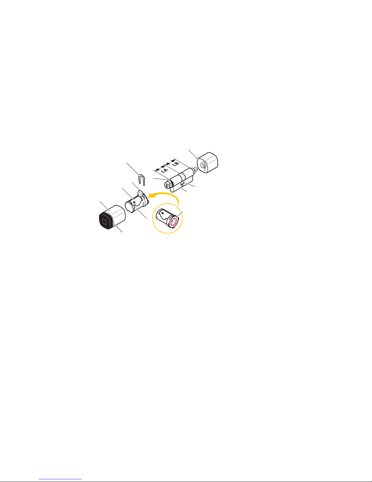
3.1.1 Structure
2
3
6
7
11
12
13
8
9
10
5
4
1
1 Outer knob 8 Securing shackle
2 Cover with light ring 9 LA, length on outer side
3 Door knob module with antenna 10 LB, length on inner side
4 Battery 11 Cylinder housing
5 Contact protection film 12 Cam
6 O-ring, Ø 15 x 1mm 13 Inner knob
7 MC insert
Table1:
Structure – Description of standard version
3.2 Scope of delivery
• 1 digital cylinder
• 1 forend locking stud
• 1 battery, CR2 lithium type
• 1 set of instructions
3.2.1 Also for dual digital cylinder
• 1 battery, CR2 lithium type
3.3 Accessories
• Relevant system software and programming tools
Page 12
Product description Technical Manual
12 1220013692 - 11/2017dormakaba digital cylinder
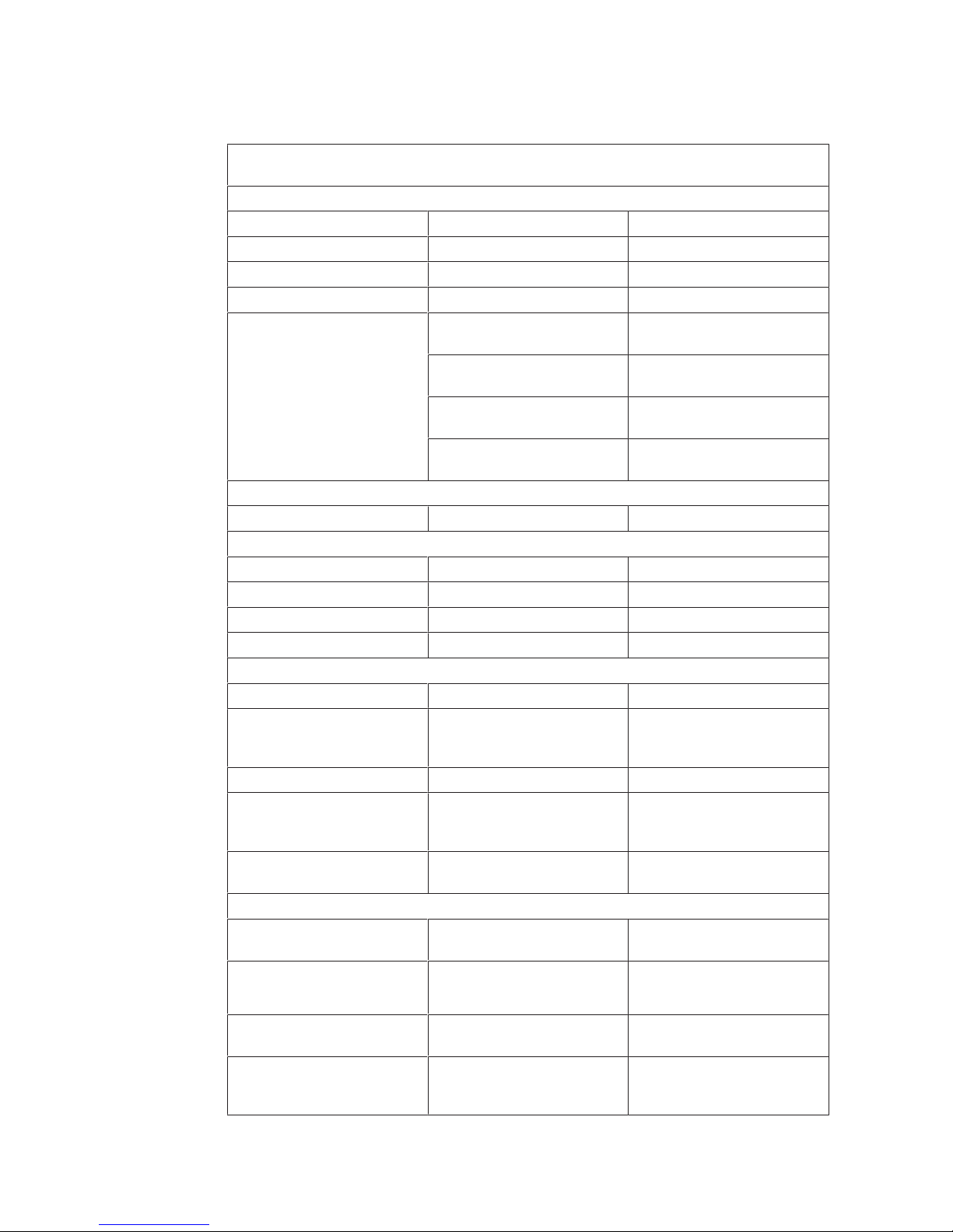
3.4 Technical data
The digital cylinder is intended for use in building doors that are equipped with a lock.
Technical data
Dimensions
Outer knob Ø x L 36 x 45mm
Inner knob Ø x L 36 x 29mm
Small inner knob Ø x L 30 x 27mm
Dual inner knob Ø x L 36 x 45mm
Backset 35mm Door opens inwards
(all variants)
30mm Door opens outwards
(standard inner knob)
35mm Door opens outwards
(dual inner knob)
25mm Door opens outwards
(small inner knob)
Power supply
Battery 3V, CR2 lithium
Radio interface
Technology IEEE802.15.4
Frequency band 2400 to 2485.5MHz
Transmission power + 8dBm
Receiver sensitivity - 102dBm @ 1% PER
Ambient conditions
Protection type IP56 Outer knob (standard)
Temperature -25°C – +70°C The temperature range de-
pends on the battery manu-
facturers' specifications.
Humidity 0%–95% rH, non-condensing
Climate Not suitable for heavily cor-
rosive atmospheres (chlorine,
ammonia).
Rooms Not to be used in potentially
explosive environments.
Standards
VdS ‘Protected’ version:
class BZ+
Classification according to
EN15684
Place:
Classification:
1 2 3 4 5 6 7 8
1 6 B 4 A F 3 2
Resistance to fire EN 1634-2: 95min Version 1439 and 1539 from
total length 85mm
Durability > 200,000 cycles
EN 1303 class 6
EN 179/EN 1125 class 7
Page 13
Product descriptionTechnical Manual
131220013692 - 11/2017 dormakaba digital cylinder
Technical data
Corrosion DIN EN 1670 class 3
DIN EN ISO 6988, severity
level 3 (SO2 test)
Dimensions DIN18252 Profile cylinder
SN-EN1303 Round profile cylinder
Cycles
Battery life at 20°C Approx. 50,000 cycles Dependent on the configura-
tion used
Battery life at -20°C EXT version:
approx. 40,000 cycles
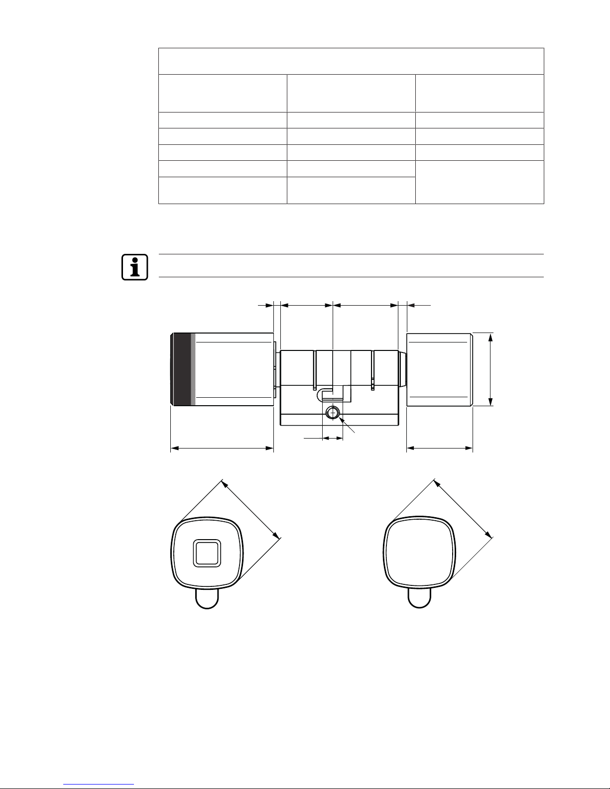
3.4.1 Dimensions
The dimensions stated also apply for the 22mm round profile cylinder.
45
29
32
1431
3 4
36
36
9,2
25 LB
M5
Dimension drawing 1431 Asymmetrical (profile cylinder)
Page 14
Product description Technical Manual
14 1220013692 - 11/2017dormakaba digital cylinder
45
32
M5
LA3 10.5
36
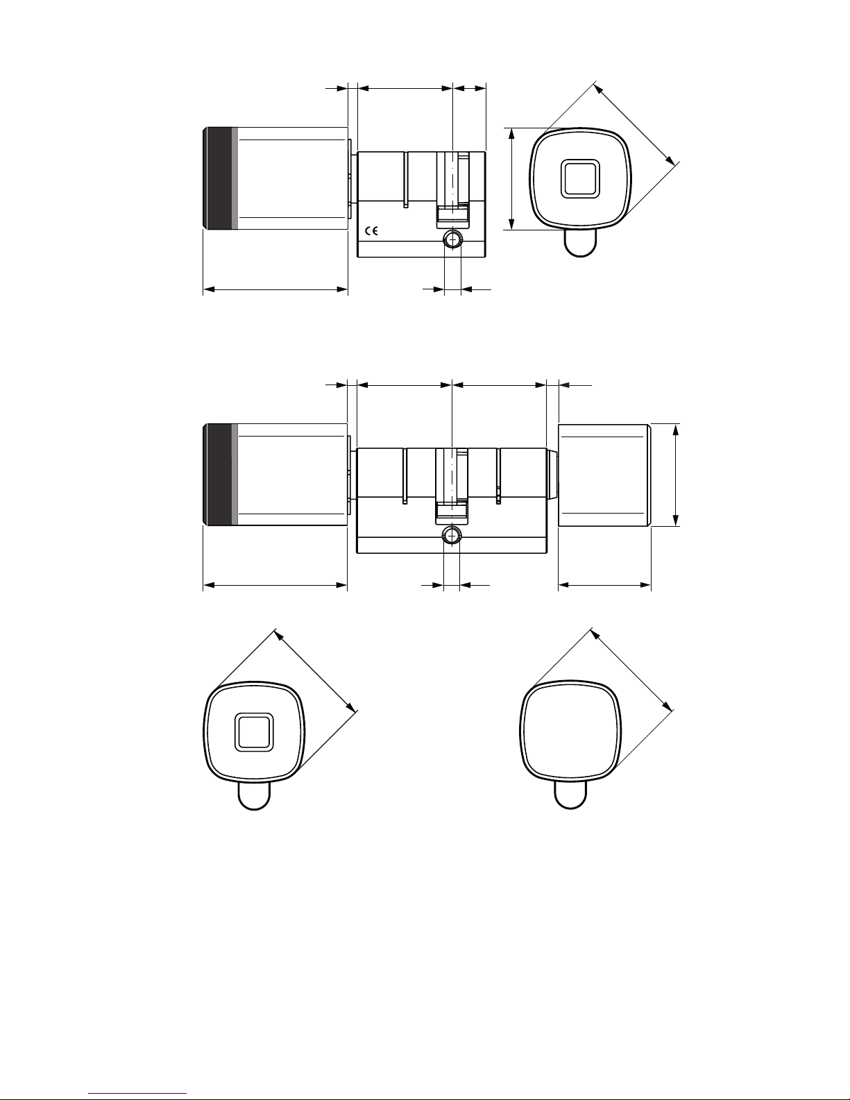
1434
Dimension drawing 1434 Half with outer knob profile (profile cylinder)
45
29
32
M5
LA
1435
3 4LB
36
36
Dimension drawing 1435 Standard (profile cylinder)
Page 15

Product descriptionTechnical Manual
151220013692 - 11/2017 dormakaba digital cylinder
45
27
26
M5
LA3 3.5LB
30
32
36
1437
Dimension drawing 1437 Anti-panic, small inner knob version (profile cylinder)
45
32
M5
LA3 3LB
45
36
1439
Dimension drawing 1439 Dual (profile cylinder)
Page 16

Product description Technical Manual
16 1220013692 - 11/2017dormakaba digital cylinder
3.5 Conformity
This product conforms to the EU directives
2014/53/EU Radio Equipment Directive
2014/35/EU LVD Directive
2011/65/EU RoHS Directive
You can download the original declaration of conformity in PDF format at www.kaba.com/con-
formity.
Page 17

InstallationTechnical Manual
171220013692 - 11/2017 dormakaba digital cylinder
4 Installation
This chapter describes the installation of the product.
4.1 Requirements
4.1.1 Door components
Locking cylinder
The locking cylinder with Euro profile or round profile can be used in any door made from
wood, glass or metal, in accordance with the cylinder perforations.
A notch is required for the locking cylinder with the anti-panic round profile cylinder as this
has a pin going all the way through on the inside (LB).
The locking cylinder with the Euro profile cylinder and dual round profile cylinder, in the protected version (VdS class BZ+) only offers high anti-drill protection on the outside (LA).
WARNING
Risk of personal injury or death.
• Improper use or incorrectly installed digital cylinders can lead to emergency exit locks or
panic door locks and doors not opening.
• The use of a digital cylinder must be checked carefully before using it in locks with a panic
function.
• Before installing the digital cylinder in an escape door, a check must be carried out to ensure that the function of the lever handle or the panic push bar is not obstructed by the
inside knob.
• The use of a digital cylinder in emergency exit locks in accordance with EN179 or in panic
door locks in accordance with EN1125 is documented in the lock manufacturers' performance declarations. If the digital cylinder is not listed in the performance declarations or
certificates from the lock manufacturer or the lock does not comply with these standards,
an EC conformity inspection of the lock, digital cylinder, fitting and assembly accessories
as one unit must be carried out.
NOTICE
Danger of damage to electronic components from electrostatic discharge.
Improper handling can damage or destroy electrostatically sensitive circuit board components.
• Observe and apply general ESD protective measures.
Check the dimensions
The following dimensions are to be checked prior to installation:
Page 18

Installation Technical Manual
18 1220013692 - 11/2017dormakaba digital cylinder
>2 LA LB >2
D
1. Check the door thickness with the fittings (LA and LB)
and the cylinder length.
2. Check the profile cut-out and the backset (D).
• In order for the multitool to be inserted between the knob and the plate, choose cylinder
lengths so as to retain at least a 2mm gap between the plate and the knob.
• In accordance with DIN 18257 for security hardware and security plates, in doors with security hardware (burglary-resistant fitting) the cylinder housing should not protrude more
than 3mm from the external plate.
• Determine the length of the forend screw: Forend screw ≥ backset + 10mm.
4.1.2 Tools required
• Tool – Multitool
• Allen key, small inner knob, 2mm hex
• Flat head and Phillips screwdriver
• Programming cable
• Adaptor/programming pin
Page 19

InstallationTechnical Manual
191220013692 - 11/2017 dormakaba digital cylinder
4.2 Installation versions
NOTICE
When installing the lock, there is a risk of being locking out.
Always install the digital cylinder when the door is open. This prevents you from locking yourself out when using self-locking locks.
The locking cylinder in the digital cylinder version without an inner knob and the dual version
should be programmed before carrying out the function test. After this, hold an authorised
user medium in front of the cylinder and carry out the function test by turning the outer door
knob.
With installation version A, remove the inner door knob and push the cylinder through the fitting and the lock from the outer side of the door.
With installation version B, remove the outer door knob and also the inner door knob if necessary, and push the cylinder housing through the door's lock.
Digital cylinder installation versions
Installation versions
Type A B
1431 Asymmetrical
1435 Standard
recommended optional
1433 Half with turning range
1434 Half
— optional
1437 Anti-panic recommended optional
1439 Dual — recommended
1531 Asymmetrical
1535 Standard
not recommended recommended
1533 Half with turning range
1534 Half
— optional
1537 Anti-panic
1
not recommended optional
1539 Dual — recommended
Key:
1
The fitting needs a recess on the inner side for the cylinder pin.
Page 20

Installation Technical Manual
20 1220013692 - 11/2017dormakaba digital cylinder
4.2.1 Installation version A
1
2
3
1. Remove the outer door knob.
2. Remove the contact protection film.
3. Attach the outer door knob.
4
4. Position the multitool on the outer door knob.
5
5. Turn the multitool to the left and lock it.
The outer door knob and the cylinder housing are now
firmly connected.
6
7
6. Align the cam flush with the cylinder housing.
7. From the outer side of the door, push the digital cylinder
through the fitting and the lock.
8
8. Position the forend locking stud in the lock and tighten it
slightly.
Click!
9
9. Note:
Align the locking spring and the notch with each other!
Place the inner door knob on the cylinder housing.
10
10. Tighten the forend locking stud.
Page 21

InstallationTechnical Manual
211220013692 - 11/2017 dormakaba digital cylinder
11 11
11. Check that the door knobs function correctly.
Both door knobs can be turned without touching the fittings.
12. Check the backset.
The door knobs must not knock against the door frame.
Page 22

Installation Technical Manual
22 1220013692 - 11/2017dormakaba digital cylinder
4.2.2 Installation version B
1
1. Remove the outer door knob.
2
3
4
2. Attach the multitool to the securing shackle from below.
3. Pull out the securing shackle.
4. Remove the knob module.
5
6
5. Align the cam flush with the cylinder housing.
6. Push the cylinder housing through the lock from the inner
side of the door.
7
7. Position the forend locking stud in the lock and tighten it
slightly.
8
8
8. Install the fittings.
9
9. Note:
Align the locking spring and the notch with each other!
Place the inner door knob on the cylinder housing.
Page 23

InstallationTechnical Manual
231220013692 - 11/2017 dormakaba digital cylinder
10
10. Put the inner door knob on to the cylinder housing.
11
11. Push the securing shackle into the knob module from
above until it stops.
The knob module and cylinder housing are then firmly connected.
13
12
12. Remove the contact protection film.
13. Note:
Be careful not to tilt the edge of the knob when installing.
Push the outer door knob over the door knob module.
14
15
14. Position the multitool on the outer door knob.
15. Turn the multitool to the left and lock it.
The outer door knob and the cylinder housing are now
firmly connected.
16
16. Tighten the forend locking stud.
17 17
17. Check that the door knobs function correctly. Both door
knobs can be turned without touching the fittings.
18. Check the backset.
The door knobs must not knock against the door frame.
Page 24

Installation Technical Manual
24 1220013692 - 11/2017dormakaba digital cylinder
4.2.3 Function check on anti-panic digital cylinder
After installing an anti-panic digital cylinder, a function check must be carried out.
WARNING
Risk of personal injury or death.
• After installing the digital cylinder in a panic lock, a function check must be carried out.
It must be possible to open the lock with the lever handle in all cam rest areas.
• For emergency exit or panic door locks, it is vital that the specifications of the lock and fittings manufacturers are observed.
A spring mechanism in the locking cylinder ensures that the cam cannot be positioned in an
area that is not authorised for panic locks.
39
6
12
a) upper authorised rest area
39
6
12
b) lower authorised rest area
Check the reset function as shown:
Check that the lock functions correctly
39
6
12
1. Turn the inner door knob upwards until it cannot be reset.
(Rest area pointing up at 12 o'clock).
Note: If there is no inner door knob, use the outer door
knob.
2. Press the handle.
The lock should unlock.
39
6
12
3.4.Turn the inner knob downwards until it cannot be reset.
(Rest area pointing down at 6o'clock.)
Press the handle.
The lock should unlock.
Check that the locking cylinder is functioning correctly
3
6
12
1. Turn the inner door knob to the 11 o'clock position and release it.
The inner door knob should turn back automatically.
3
6
12
2. Turn the inner door knob to the 1 o'clock position and release it.
The inner door knob should turn back automatically.
Page 25

ProgrammingTechnical Manual
251220013692 - 11/2017 dormakaba digital cylinder
5 Programming
This section describes how to program the components.
Prior to first use, all components must be programmed with the relevant access authorisa-
tions for the user media. Components with a wireless function should be activated in the system.
Manual programming using master media or the programmer 1460 is described in the document
Programming Kaba evolo components
.
The process for setting up the wireless function is described in the handbook for the relevant
system software.
5.1 Initial programming of MRD components
When first used, multi-RFID (MRD) components are set to the technology in which the components are used with a master LEGIC or MIFARE. The components then behave as defined
for the authorisation types LEGIC (LEA) or MIFARE (MID).
Note: After an INI reset using master media, the components must then be re-programmed
using a master LEGIC or MIFARE.
5.2 Initial programming of LEGIC® and MIFARE components
Prior to first use and on request, all components must be programmed with the access authorisation corresponding to their User media. The access authorisations for User media can
be transferred to the components using various types of programming.
5.3 Master media
With the A master and B master media, the components are programmed directly. The B
masters are organised under an A master. The master media do not have any access authorisations.
5.4 User media
All User media are organised under a B master.
NOTICE
Lost User media should be immediately blocked and deleted from all components.
(Delete lost User media in the system software in the whitelist (add CardLink to the blacklist)
or delete all User media with the corresponding master and then re-program all User media).
Page 26

Programming Technical Manual
26 1220013692 - 11/2017dormakaba digital cylinder
5.5 Program structures
All components can be organised manually in an A/B structure or in a B structure.
In the A/B structure, up to 200 B masters can be created with one A master. The User media
cannot be directly programmed in an A structure.
Separate access authorisations to User media can be issued with each B master. User media
can be programmed with different B masters but not with the same components.
Each component can be programmed with up to 4000 User media. These can be distributed
across the various B masters as required. For example, a B1 master only manages 50 users
whilst another master, B2, manages up to 3950 users.
5.6 A/B and B structures
A/B structure
A master
B structure B master
User media
Page 27

ProgrammingTechnical Manual
271220013692 - 11/2017 dormakaba digital cylinder
5.7 Programming user media with B masters
Components confirm the detection of media with acoustic and visual signals.
In this case, the light ring glows green for as long as the medium is located within the antenna
field and is read.
Programming the
User media
Action
1
1 s
Beep
Launch programming mode:
Master B approx. 1 s hold in front
of the antenna.
1 x short
2
1 s
Beep
Program User media:
User media approx. 1 s hold in front
of the antenna.
1 x short
3
1 s
Beep
Additional User media approx. 1 s
hold in front of the antenna.
1 x short
4
Beeeep
1 s
To complete:
Master B approx. 1 shold in front of
the antenna.
Note: If no master medium is held
up within 20 seconds, programming mode ends automatically and
one long acoustic signal sounds.
1 x long
Page 28

Programming Technical Manual
28 1220013692 - 11/2017dormakaba digital cylinder
5.8 Deleting individual user media
In this case, the light ring glows green for as long as the medium is located within the antenna
field and is read.
Deleting
User media
Action
1
1 s
Beep
Launch programming mode:
Master B approx. 1 s hold in front
of the antenna.
1 x short
3 s
2
Beep
Beep
Delete User media:
User media approx. 3 s hold in front
of the antenna.
2 x short
3
Beeeep
1 s
To complete:
Master B approx. 1 shold in front of
the antenna.
Note: If no master medium is held
up within 20 seconds, programming mode ends automatically and
one long acoustic signal sounds.
1 x long
Page 29

ProgrammingTechnical Manual
291220013692 - 11/2017 dormakaba digital cylinder
5.9 Deleting individual B masters
NOTICE
All User media under Master B and the Master B medium under Master A are deleted.
In this case, the light ring glows green for as long as the medium is located within the antenna
field and is read.
Deleting Master Bs Action
1
1 s
Beep
Launch programming mode:
hold in front of the antenna. Mas-
ter A approx. 1 s
1 x short
10 s
2
Beep
Beep
Delete Master B and all user media:
Master B approx. hold in front of
the antenna. 3s
2 x short
3
Beeeep
1 s
To complete:
Master A approx. 1 s hold in front
of the antenna.
Note: If no master medium is held
up within 20 seconds, programming mode ends automatically and
one long acoustic signal sounds.
1 x long
Page 30

Programming Technical Manual
30 1220013692 - 11/2017dormakaba digital cylinder
5.10 Deleting all user media
Components should not be in programming mode.
In this case, the light ring glows green for as long as the medium is located within the antenna
field and is read.
Deleting
user media
Action
10 s
1
Beep
Beep
hold in front of the antenna. Master B approx. 10 s
All User media under the Master B
are deleted.
2 x short
1 x long
1
1 x short
Key:
1
Firmware version 42xx
Page 31

ProgrammingTechnical Manual
311220013692 - 11/2017 dormakaba digital cylinder
5.11 INI reset with master media for whitelist and CardLink™
An INI reset can be used to restore the factory settings for the components.
NOTICE
All User media and master media as well as the traceback are deleted.
Components should not be in programming mode.
INI reset for whitelist
In this case, the light ring glows green for as long as the medium is located within the antenna
field and is read.
INI reset with master Action
15 s
1
Beep
Beep
Master B structure
Master B approx. 15 s hold in front
of the antenna. The INI reset will be
executed after 15 s.
After 10 s,
1 x long,
1 x short,
after 15 s,
2 x short
15 s
1
Beep
Beep
Master A/B structure
Master A approx. 15 s hold in front
of the antenna. The INI reset will be
executed after 15 s.
After 10 s,
1 x long,
1 x short,
after 15 s,
2 x short
Page 32

Programming Technical Manual
32 1220013692 - 11/2017dormakaba digital cylinder
INI reset for CardLink
In this case, the light ring glows green for as long as the medium is located within the antenna
field and is read.
INI reset with master Action
15 s
1
Beep
Beep
B master
Master B approx. 15 s hold in front
of the antenna. The INI reset will be
executed after 15 s.
2 x short
15 s
1
Beep
Beep
Master A
Master A approx. 15 s hold in front
of the antenna. The INI reset will be
executed after 15 s.
2 x short
Page 33

OperationTechnical Manual
331220013692 - 11/2017 dormakaba digital cylinder
6 Operation
This section describes operation of the product.
6.1 Operating the digital cylinder
The digital cylinders are operated with user media. The lock can only be operated if the user
media has an access authorisation. Unauthorised user media are rejected.
6.2 Opening with user media
Before being used for the first time, access authorisations for the relevant system software
must be transmitted to the User media.
1
1. Hold the authorised user medium with the valid access authorisation in front of the knob.
2
2. Access authorisation will be signalled by an acoustic signal1 and a visual display1.
Note: The digital cylinder's opening time is limited; after this time has elapsed, the digital
cylinder closes automatically. Upon delivery, the opening time is approx. 6 s, but this can
be adjusted using the 1460 programmer or the system software.
3
3. Activate the lock by turning the door knob.
ð The door can be opened.
Beep
Beep
Beep
Beep
If there is an attempt to gain access using unauthorised user media, the acoustic1 signal will
sound 4 times and the red1 light will briefly flash 4 times.
Key:
1
If both functions have been activated using the 1460 programmer or the system software.
Page 34

Maintenance Technical Manual
34 1220013692 - 11/2017dormakaba digital cylinder
7 Maintenance
This section describes product maintenance.
7.1 Maintenance table
The component's mechanism and/or electronics do not require any maintenance.
NOTICE
Opening the mechatronic unit.
Opening the mechatronic unit releases the manufacturer from any liability under the guarantee.
Maintenance interval
Components Measures Interval
Digital cylinder
all versions
Function check as specified in the instructions
for the components
12 months
Replacing the batteries ≤ 24 months
Clock (components) Check and set clock time with the system soft-
ware (the clock time is updated with every programming procedure)
12 months
Firmware update For functional modifications as required
7.2 Maintenance of escape doors
WARNING
Risk of personal injury or death.
The service life of the digital anti-panic cylinder is limited by the spring mechanism.
Consequently, they must be replaced by the manufacturer after 10 years.
WARNING
Risk of personal injury or death.
For emergency exit locks in accordance with EN 179 and panic door locks in accordance with
EN 1125, comply with the lock manufacturer's maintenance advice.
Function check on anti-panic digital cylinder
As part of maintenance on a panic lock, also carry out a function check on the anti-panic digital cylinder. (See Chapter Function check on anti-panic digital cylinder [}4.2.3].)
Page 35

MaintenanceTechnical Manual
351220013692 - 11/2017 dormakaba digital cylinder
7.3 Cleaning
Only disinfection agents that are explicitly formulated for cleaning delicate metal surfaces
and plastics may be used. The use of unsuitable cleaning agents or methods can damage the
components' surface.
1. Use a soft, damp cloth to clean the surface.
Page 36

Service Technical Manual
36 1220013692 - 11/2017dormakaba digital cylinder
8 Service
NOTICE
Do not oil the Digital cylinder!
8.1 Serial numbers
The digital cylinder's serial number can be found on the cylinder housing next to the matrix
code. The first 5 digits indicate the manufacturing date.
The manufacturing date can be worked out as follows:
1. Enter the first 5 digits into any cell in an Excel sheet.
2. Right click > Choose Format cells.
3. In the Numbers tab, select the Date category.
4. Select the type 14.03.2001.
Using this procedure, 41038 indicates the manufacturing date of 09/05/2012.
8.2 Replacing the battery
Whilst the battery is being changed, all the data (access authorisations, configurations and
traceback) is retained in the battery-independent memory. The clock settings are lost after 45
seconds.
Requirements:
• New battery available
• Tool – Multitool available
Do not use rechargeable batteries or accumulators.
1
2
1. Position the multitool on the inner side of the outer door
knob.
2. Turn the multitool to the left and unlock the outer door
knob.
3
4
3. Remove the outer door knob.
4. Remove the spent battery.
Page 37

ServiceTechnical Manual
371220013692 - 11/2017 dormakaba digital cylinder
1
2
Note:
If necessary, remove it using the multitool.
5
5. Note:
Make sure you check the polarity of the battery!
Insert the new battery.
Note:
After inserting the battery, the LEDs will briefly flash green
once.
The component is now ready again.
6
6. Push the outer door knob over the door knob module.
7
8
7. Position the multitool on the outer door knob.
8. Turn the multitool to the left and lock it.
The outer door knob and the cylinder are now firmly connected.
9
9. Check that the digital cylinder is functioning correctly.
10. Check theclock time [}8.5] and adjust if required.
Page 38

Service Technical Manual
38 1220013692 - 11/2017dormakaba digital cylinder
8.3 Replace e-module
Prerequisite:
• new e-module available
• tool – multitool available
• knob has been removed.
The different versions of the e-modules are as follows:
MRD e-module and wireless versions
The INI reset contacts are on the round PCB on the front.
LEGIC e-module
The INI reset contacts are on the PCB on the side.
MIFARE e-module
The INI reset contacts are on the PCB on the top.
Procedure for all versions:
1. Remove the battery.
2. Using the multitool, slide [}4.2.2]the securing shackle out of the guide.
3. Carefully remove the e-module.
4. Insert the new e-module.
5. Push the securing shackle into the door knob module from above, to the end stop position.
ð The door knob module and the cylinder housing are now firmly connected.
6. Insert the battery.
ð After it has been inserted, the LEDs will briefly flash green once.
ð The component is now ready again.
7. Attach the door knob.
Page 39

ServiceTechnical Manual
391220013692 - 11/2017 dormakaba digital cylinder
8.4 Disassembling the inner door knob
8.4.1 'Click' door knob
ü Tool – Multitool ready
2
2
1
3
1. Insert the multitool with the narrow pawl between the Knob and the fitting.
2. Press the multitool against the fitting.
ð The locking spring will release.
3. Remove the Thumbturn knob.
8.4.2 'Small' inner knob
ü Allen key, 2mm hex available
2 mm
1. Using the hexagonal key, loosen the screw from the inner door knob.
2. Remove the door knob.
8.5 Configuration and traceback
Correctly set values for date and time ensure time management with the components is upto-date.
Components connected to the system software via the wireless function are updated via the
gateway (e.g. clock time, configurations). The traceback can be read using the system software.
In standalone mode, configurations can be transmitted using the programmer or can be
changed with this (e.g. adjusting the clock time).
A programmer can read the traceback and transmit it to the system software for evaluation.
Further steps are described in the documents
Programmer 1460
and
Programmer 1364
.
8.6 Reset (INI reset)
INI reset of e-module
An INI reset can be used to restore the factory settings for the components.
NOTICE
Loss of data
With an INI reset, all previously saved settings and data on the E-module are deleted.
NOTICE
Before components are returned to Kaba for servicing, always carry out a
reset on the components.
Page 40

Service Technical Manual
40 1220013692 - 11/2017dormakaba digital cylinder
8.6.1 Reset with master media
INI reset can be used to restore the factory settings for the components. (See chapter in operating instructions 'Programming and signals for Kaba evolo components' INI reset with
master media for whitelist and CardLink™ [}5.11].)
8.6.2 Reset using programmer 1460
1. Hold valid master medium in front of the component's antenna.
2. Open Settings menu.
3. Select Actuator.
4. Select INI reset.
5. Select Yes.
ð Successful INI reset is confirmed using an acoustic signal.
Additional steps are described in the
programmer 1460
document.
8.6.3 Reset using tweezers
INI reset with tweezers and valid master media
The components have INI reset contacts on the e-module.
To perform an INI reset, short-circuit these contacts
with electrically conductive tweezers.
Before short-circuiting, present a valid master medium or user medium.
1. Disassemble Knob.
2. Localise both contacts on the e-module. (See Chapter Replace e-module [}8.3].)
3. Using the tweezers, short-circuit the INI reset contacts for approx. 3 s.
ð Successful INI reset is confirmed using an acoustic signal.
8.7 Emergency power supply
If all the alarm signals are ignored until the batteries are completely flat, doors can no longer
be opened from the outside with the digital cylinder. In this case, insert a new battery.
The digital cylinder does not require an emergency power supply using the 1460 programmer.
Page 41

TroubleshootingTechnical Manual
411220013692 - 11/2017 dormakaba digital cylinder
9 Troubleshooting
This chapter provides important information for analysing errors and troubleshooting.
9.1 Error analysis
Symptoms Possible causes Measures
The use of a master or user
medium is confirmed via various acoustic and/or visual
signals by the components
1 x very
short
9 x
flashes
red
5
– Battery 'Low'
(V4 FW 42.XX)
– Replace the batteries
The use of a master or user
medium is confirmed via various acoustic and/or visual
signals by the components
9 x very
short
5
—
2
– Battery 'Low'
(V4 FW 42.XX)
2
– Replace the batteries
The use of a master or user
medium is confirmed via various acoustic and/or visual
signals by the components
2 x
long
after 4
s
1 x
short
green
5
– Battery 'Low'
(V3 FW 31.XX/32.XX)
2
– Replace the batteries
Door does not open: authorisation via an authorised user
medium is confirmed by
acoustic signals
1 x very
long
— – Alarm — Battery "Empty" – Replace the batteries
Door does not open: authorisation by an authorised user
medium is confirmed via
acoustic and visual signals
8 x
short
8 x
short
red
– Self-test could not be completed.
3
– Check or replace the coupling unit
Door does not open: authorisation by an authorised user
medium is confirmed via
acoustic and visual signals
4 x
short
4 x
short
red
– Medium not programmed
– Outside the time window
– Program medium
– Check time profiles
Door does not open: authorisation by an authorised user
medium is confirmed via
acoustic and visual signals
1 x long
1 x
short
1 x long
1 x
short
green
– Internal clock in component
has failed
– Check programming and
clock time
User medium cannot be programmed
— — – 4000 media or groups
already programmed in the
e-module
– Faulty medium
– Not the correct technology
– Contact customer service
Master medium cannot be
programmed
1 x
short
1 x red – E-module already pro-
grammed
– Carry out INI reset
Master medium is not detected
— — – No power supply – Check batteries or power
supply
Incorrect e-module on digital
cylinder
— 3 x red
flash
– E-module knob and MC insert are not compatible
(V4 FW 42.XX)
– Check compatibility
Other errors — 1 x
short
red
– Unintentional re-start —
Page 42

Troubleshooting Technical Manual
42 1220013692 - 11/2017dormakaba digital cylinder
Symptoms Possible causes Measures
1 x
short
green
1 x
short
red
Other errors 1 x
short
1 x long
1 x
short
—
2
– Unintentional re-start —
Key:
2
Components without visual display
3
Function only for c-lever, mechatronic cylinder and digital cylinder
5
The actuator subsequently opens
Page 43

TroubleshootingTechnical Manual
431220013692 - 11/2017 dormakaba digital cylinder
9.2 Error analysis for battery life
Symptoms Possible causes Measures
Battery life deviates significantly
from expectations
– More accesses than anticipated – Read out traceback and check
– Low temperatures
– Firmware version not up-to-date – Carry out update to current firm-
ware version
– Programming/configuration with
non-used functions
– Adjust programming/configura-
tion
– Battery was not new – Insert new, recommended battery
– Batteries that look identical can
contain different amounts of energy
– Insert new, recommended battery
– E-module knob with battery installed was stored separately from
digital cylinder
– Install new battery
– Store e-module knob without
battery
– Defective electronics – Contact customer service
– Activation of digital cylinder
without RFID medium, e.g. by holding your hand in front of it
– Inform user
– Many unauthorised access attempts (unauthorised access requires more energy than authorised
access)
– Clarify causes
– Coupling monitoring often active – Carry out update to current firm-
ware version
Page 44

Appendix Technical Manual
44 1220013692 - 11/2017dormakaba digital cylinder
10 Appendix
This chapter provides additional information about the battery operation.
10.1 Summary of various factors influencing the battery
operation
The digital cylinder operates with a 3V CR2 lithium battery.
The battery life is affected by the following factors:
• Number of accesses and actions (frequency of use)
• Programming/configuration of components
• Battery type
• Battery manufacturer
• Ambient temperature
• Firmware version
• Hardware version (standard INT or extremely low temperature EXT)
10.2 Recommendations for battery operation
• Always use the up-to-date firmware version for the products.
• Always only activate the functions actually required.
• Record the battery replacement date in a maintenance plan.
If the battery life does not meet expectations, determine the cause in accordance with
Chapter [}9.2].
• When the battery is 'low', replace immediately.
• Explain to user the 'low' battery warning signal and urge them to report the 'low' battery
warning to the person responsible immediately.
• Keep a stock of currently recommended batteries:
– Panasonic CR2 Industrial (made in Japan or Indonesia)
– Panasonic CR2 PHOTO Power (made in Japan or Indonesia)
– Duracell Ultra CR2 (made in Japan or Indonesia)
 Loading...