

Page 1
dormakaba
c-lever pro
Option: TouchGo
HAC Standard fixing - 02/2018
EN
Technical Manual
Page 2

dormakaba Schweiz AG
Hofwisenstrasse 24
8153 Rümlang
Switzerland
T: +41 (0)44 818 93 11
www.dormakaba.com
dormakaba Schweiz AG
Mühlebühlstrasse 23
8620 Wetzikon
Switzerland
T: +41 (0)44 931 61 11
www.dormakaba.com
dormakaba EAD GmbH
Albertistrasse 3
78056 Villingen-Schwenningen
Germany
T: +49 7720 60 30
www.dormakaba.com
Registered in: Heiligenhaus
Copyright © dormakaba 2018
All rights reserved.
No part of this document may be reproduced or used in any form or by any means without prior written permission of dormakaba Schweiz AG.
All names and logos of third-party products and services are the property of their respective owners.
Subject to technical changes.
HAC Standard fixing - 02/2018
Page 3

Technical Manual
3HAC Standard fixing - 02/2018 dormakaba c-lever pro
1 About this document 5
1.1 Validity 5
1.2 Target group 5
1.3 Contents and purpose 5
1.4 Availability of the documents 6
1.5 Supplementary documents 6
1.6 Abbreviations/definition of terms 7
1.7 Hazard categories 8
1.8 Notes 8
1.9 Symbols 8
2 Basic safety instructions 9
2.1 Designated use 9
2.2 Product changes 9
2.3 Assembly and installation 9
2.4 Service and maintenance 9
2.5 ESD prevention measures 10
2.6 Handling of lithium batteries 11
2.7 Escape doors, fire protection, mortise locks 11
3 Product description 12
3.1 Overview 12
3.2 Structure 13
3.3 Scope of delivery 14
3.4 Technical data 16
3.4.1 Dimensions 17
3.4.2 Conformity 18
4 Installation 19
4.1 Installation requirements 19
4.1.1 General 19
4.1.2 Door thickness 19
4.1.3 Mortise lock 19
4.2 Replace c-lever with c-lever pro 19
4.3 Spindle standoff 20
4.4 Drilling fixing holes 20
4.4.1 With drill jig / door side 1 21
4.4.2 With drill jig / door side 2 22
4.4.3 With drilling template / door side 1 23
4.4.4 With drilling template / door side 2 24
4.5 Installing the cylinder support 25
4.5.1 Removing the backplate, swivelling the cover out 25
4.5.2 Inserting the cylinder support 26
4.5.3 Positioning the cylinder support 27
4.5.4 Fitting the cover 27
4.6 Preparing the external fitting 29
4.7 Insert direction pin and spindle 29
4.8 Inserting and connecting the coupling unit 31
4.9 Installing the external fitting 33
4.9.1 Standard fixing 33
4.10 Determining screw length 34
4.11 Preparing the internal fitting 35
4.12 Installing the internal fitting 37
4.12.1 c-lever standard variant 37
4.13 Checking the installation 40
Page 4

Technical Manual
4 HAC Standard fixing - 02/2018dormakaba c-lever pro
4.14 Dismantling 41
4.14.1 Disassembling the internal fitting 41
4.14.2 Disassembling the external fitting 43
5 Programming 44
5.1 Programming TouchGo products 44
5.2 Initial programming of MRD components 44
5.3 Master media 44
5.4 User media 44
5.5 Program structures 46
5.6 A/B and B structures 46
5.7 Programming user media with B masters 47
5.8 Deleting individual user media 48
5.9 Deleting individual Master Bs 49
5.10 Deleting all user media 50
5.11 INI reset with master media for whitelist and CardLink™ 51
6 Operation 53
6.1 Operating TouchGo products 53
6.2 Opening with user media 53
7 Maintenance 55
7.1 Maintenance table 55
7.2 Cleaning 55
8 Service 56
8.1 Serial number 56
8.2 Replacing batteries 56
8.3 Replacing the TouchGo media battery 58
8.4 Connecting the programmer 59
8.5 Configuration and traceback 60
8.6 Reset (INI reset) 60
8.6.1 Reset with programmer 1460 60
8.6.2 Reset using tweezers 62
8.7 Firmware update 64
8.8 Emergency opening 65
8.8.1 Opening with an external power supply 65
8.9 Replacing the antenna 66
9 Troubleshooting 68
9.1 Error analysis 68
9.2 TouchGo applications error analysis 70
9.2.1 Operation error analysis 70
9.2.2 Programming error analysis 71
10 Disposal / dismantling 72
10.1 Decommissioning / dismantling 72
10.2 Disposal 72
11 Packaging/return 73
11.1 Preparing a device to be returned 73
11.2 Complete devices 73
11.3 Electronic component assemblies 73
11.4 Labelling 73
Page 5

About this documentTechnical Manual
5HAC Standard fixing - 02/2018 dormakaba c-lever pro
1 About this document
This section contains information for the proper use of this document.
1.1 Validity
This document describes the product:
Product designation: dormakaba c-lever pro
Types: 262...
Variant: Standard fixing
TouchGo option
Product designation: dormakaba c-lever pro
Types: 262y-K6/MRD/E310/HAC
262y-K6/TGO/E110/HAC
Variant: TouchGo
This document describes all product versions and all optional features and functions. Options
are subject to a charge and therefore only available if purchased.
1.2 Target group
This quick start guide is intended for skilled persons only.
The descriptions are intended for skilled persons trained by the manufacturer. The descrip-
tions are no replacement for product training.
For reasons of equipment safety, the installation, maintenance and service measures de-
scribed in this documentation should only be carried out by skilled persons in accordance with
EN 62368-1 (Audio/Video, Information and Communication Technology Equipment – Part 1:
Safety Requirements).
Skilled person is the designation for people who have the appropriate technical training and
experience in setting up the equipment. Skilled persons are expected to use their training and
experience to identify any risks to themselves and others that may arise while carrying out
these activities, and to minimise these risks as far as possible. It is the skilled person’s responsibility to ensure that the conditions stated by the manufacturer and the applicable regulations and standards are complied with when carrying out these actions.
This documentation is also used to provide information for persons with the following tasks:
• Project planning and project implementation
• Commissioning the product within the network
• Connecting the product to user software by programming customer applications
• Customer-specific adjustments with product parametrisation
1.3 Contents and purpose
The contents of these instructions are limited to the installation, operation, maintenance and
servicing of the product.
Page 6
About this document Technical Manual
6 HAC Standard fixing - 02/2018dormakaba c-lever pro
1.4 Availability of the documents
Supplementary documentation is available on the Kaba website. Technical manuals can be
found in a secured area of the website.
• Access is only granted after a valid login.
• An account must be set up before logging in for the first time.
Opening login screen:
1. Open your internet browser and go to http://www.kaba.com.
2. Choose your language in the top right-hand corner of the screen.
3. Under 'Products', choose either the 'Access Management' or 'Workforce Management'
product division.
4. In the top right-hand corner of the screen, click on the following symbol:
5. Enter your email address and password to log in or create a new account (see below).
ð The technical manuals can be found under 'Downloads'.
Creating an account:
1. Click 'Create account'.
2. Fill in the data fields and confirm your entries.
ð A confirmation link will be sent to your email address.
3. Click on the confirmation link in your email to activate your account.
1.5 Supplementary documents
• Programmer 1460 technical manual
• Documentation for the system software used
TouchGo option
• Operating manual for dormakaba TouchGo c-lever
• dormakaba TouchGo system description
Page 7
About this documentTechnical Manual
7HAC Standard fixing - 02/2018 dormakaba c-lever pro
1.6 Abbreviations/definition of terms
To make this document easier to read, the following short designations are used for the
product designations, as well as the following symbols:
Short designation Product designation
c-lever c-lever pro
Product c-lever pro
Device c-lever pro
Actuator c-lever pro
Programmer Programmer 1460
S-module S-module for c-lever pro
KEM Kaba evolo Manager
MRD Multi RFID device
HAC Handle above cylinder
HBC Handle below cylinder
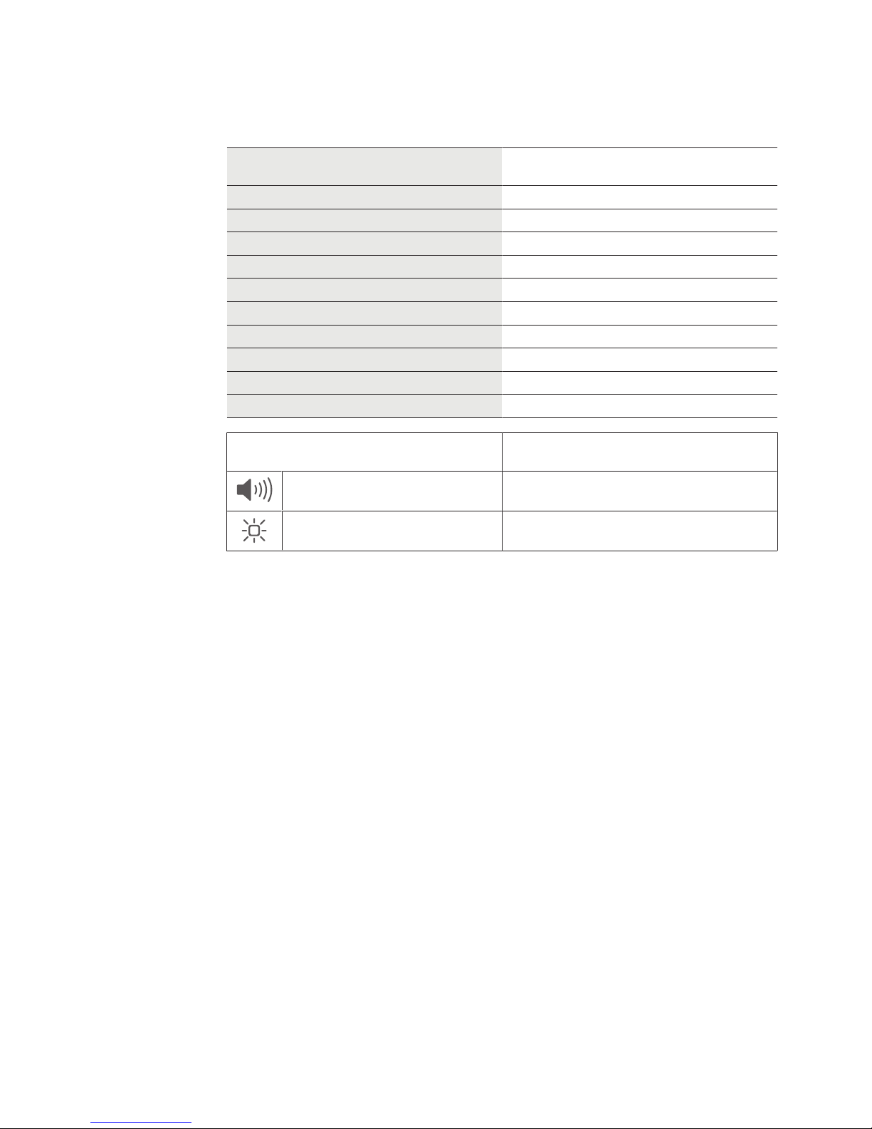
Symbols
Acoustic signal
Visual signal
Page 8
About this document Technical Manual
8 HAC Standard fixing - 02/2018dormakaba c-lever pro
1.7 Hazard categories
Instructions with information on what to do and not to do to prevent injury and material
damage are denoted specially.
Please follow all hazard instructions. These are intended to help prevent accidents and prevent damage.
These instructions are divided into the following categories:
CAUTION
Low risk
Denotes a potentially dangerous situation that could lead to minor injury.
NOTICE
Important information on the correct use of the product.
Failure to comply with these instructions could lead to malfunctions. The product and/or objects in the local vicinity could be damaged.
1.8 Notes
Information is denoted by this symbol.
Tips on using the product are useful pieces of information.
They help to make best use of the product and its functions.
1.9 Symbols
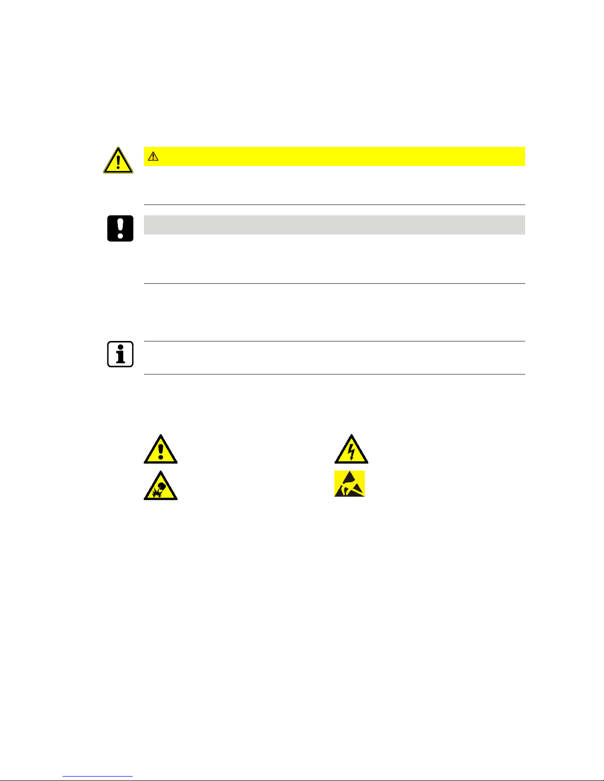
Symbols with the following meanings are used for hazards (depending on hazard source.)
General hazard Hazard from electric shock
Risk of explosion Risk to electronic components from
electrostatic discharge
Page 9
Basic safety instructionsTechnical Manual
9HAC Standard fixing - 02/2018 dormakaba c-lever pro
2 Basic safety instructions
This product has been built to state-of-the-art standards and in line with established safety
regulations. However, hazards for persons and property may arise when handling the product.
Read and observe the following safety instructions before using the product.
2.1 Designated use
This product is intended for use as specified and explained in the Product description section
only. Any other use is considered non-designated use. The manufacturer is not liable for any
damage or injury due to non-designated use. The user/facility operator is the sole person to
bear risks for non-designated use.
2.2 Product changes
NOTICE
No changes should be made to the product, unless in accordance with changes described in
the instructions.
2.3 Assembly and installation
Check the device for visible damage caused by transport or wrong storage. Do not start up
any damaged device!
Assembly and installation of the product may only be done by skilled personnel (see chapter 1
Target group).
When installing/inserting the product in end-use equipment all requirements of the mentioned test standards must be fulfilled.
The product should only be installed in locations which fulfil the environmental and technical
conditions specified by the manufacturer.
The manufacturer is not liable for damage arising due to improper handling or incorrect installation.
2.4 Service and maintenance
Conversions and modifications to the product may only be done skilled personnel (see chapter
1 Target group). Any conversions and modifications performed by other persons will exempt
us from any liability.
Opening the device will lead to exclusion of all liability and warranty.
This excludes replacing the batteries.
The elimination of faults and maintenance work may only be performed by skilled personnel
(see chapter 1 Target group).
Page 10

Basic safety instructions Technical Manual
10 HAC Standard fixing - 02/2018dormakaba c-lever pro
2.5 ESD prevention measures
NOTICE
Risk for electronic components due to electrostatic discharge.
Incorrect handling of electronic PCBs or components can result in damage which will cause a
complete breakdown or sporadic errors.
• General ESD prevention measures must be observed when installing or repairing the
product.
• Wear an anti-static wrist strap when handling electronic components. Connect the end of
the strap to a discharge box or a non-painted, earthed metal component. This way, static
discharges are channelled away from your body safely and effectively.
• Handle a PCB along its edges only. Do not touch the PCB or connectors.
• Place dismantled components on an anti-static surface or in an anti-static shielded container.
• Avoid contact between PCBs and clothing. The wrist strap protects PCBs against an electrostatic discharge voltage from the body only. However, damage can also be caused by
an electrostatic discharge voltage from clothing.
• Transport and ship dismantled modules in conductive anti-static bags only.
Page 11

Basic safety instructionsTechnical Manual
11HAC Standard fixing - 02/2018 dormakaba c-lever pro
2.6 Handling of lithium batteries
NOTICE
Lithium batteries can explode or burst explosively.
Improper handling of lithium batteries can lead to fires and explosions.
• Only replace lithium batteries with batteries of the same type.
• Do not open, drill through or squash lithium batteries.
• Do not burn lithium batteries or expose them to high temperatures.
• Do not short circuit lithium batteries.
• Do not recharge lithium batteries.
2.7 Escape doors, fire protection, mortise locks
• Make sure that the regulations for emergency exits and escape routes are observed.
• Make sure that local regulations are observed for fire door assemblies.
• Make sure that only standardised mortise locks are used.
Page 12

Product description Technical Manual
12 HAC Standard fixing - 02/2018dormakaba c-lever pro
3 Product description
This section provides an overview of the product and gives information on technical details.
3.1 Overview
c-lever pro is an electronic door fitting. The external fitting contains an antenna and a
mechatronics unit (coupling unit). Following identification of an authorised medium, the door
can be opened manually. The access authorisation is signalled visually but also acoustically if
this option is required.
TouchGo option
The TouchGo option allows you to unlock doors without having to hold a key or user medium
in your hand. Touching the door handle by hand will enable the fitting to detect whether the
individual is carrying an authorised user media. Following identification of an authorised medium, the door can be opened manually. The access authorisation is signalled visually but also
acoustically if this option is required.
Page 13
Product descriptionTechnical Manual
13HAC Standard fixing - 02/2018 dormakaba c-lever pro
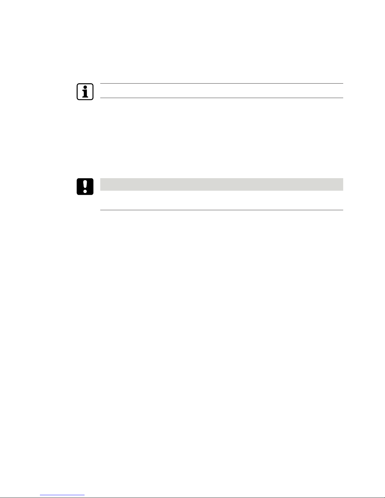
3.2 Structure
1 2 3 4 5 6 7 8 9 10 11 12 13 14 15 16
Item Internal fitting. Item External fitting.
1–10 Internal fitting 11–16 External fitting
1 Internal lever handle 11 Backplate
2 Threaded pin 12 Coupling unit with direction pin
3 Union nut 13 Frame
4 Cover 14 Union nut
5 Spindle (square pin) 15 Threaded pin
6 M5 screws (2 pieces) with
special washers (2 pieces)
Elongations (2 pieces)
16 Outside lever handle
7 Frame
8 Battery holder
9 Batteries, AA lithium
(2 pieces)
10 Backplate with screws
TouchGo option
Plastic sleeve for spindle
(Delivered assembled)
Plastic sleeve for connection mandrel
(Delivered assembled)
Page 14
Product description Technical Manual
14 HAC Standard fixing - 02/2018dormakaba c-lever pro
3.3 Scope of delivery
• 1 inside unit • 1 antenna cable
• 1 external fitting • 2 batteries, AA lithium
• 1 coupling unit • 1 drilling template
• 1 direction pin • Screws and elongations depending on
variant
• 1 spindle • Crimping tool (option)
• 1 inside lever handle • Adapter for programmer 1355-42B (option)
• 1 outside lever handle
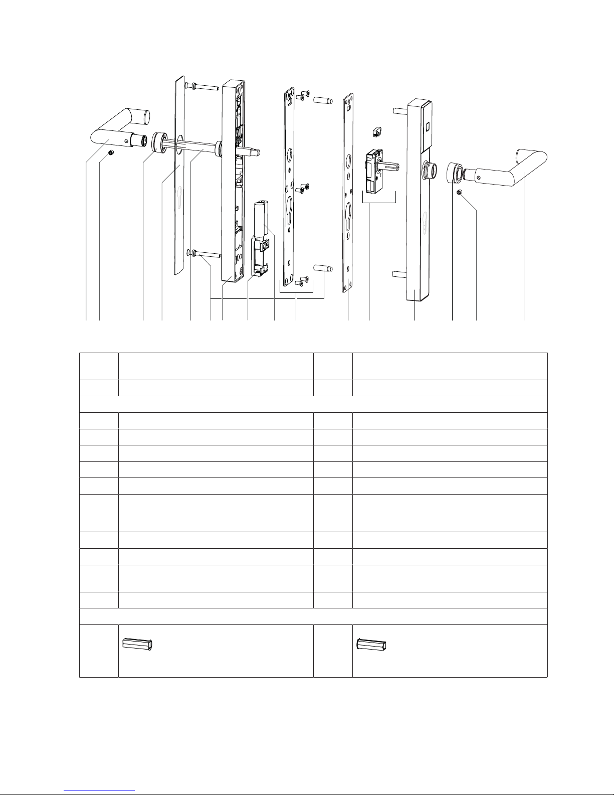
Overview of backplates
The backplates of the internal fitting are the same as the ones for the external fitting. “Narrow-wide variant”: The backplates of the internal fitting and the external fitting are different.
1 2 3 4 65 7 8
Item Backplate designation
(profile hole measurement in mm)
1 PZ 98 / SK 105
2* PZ 85, 88, 90, 92
RZ 94
AU 90
3 PZ 70, 72, 78
RZ 74, 78
4 Blind
5 PZ 98,
SK 105
6* PZ 85, 88, 90, 92
RZ 94
7 PZ 70, 72R, 78
RZ74, 78
8 Blind
* *Version described in this document
Page 15
Product descriptionTechnical Manual
15HAC Standard fixing - 02/2018 dormakaba c-lever pro
Key
Abbreviation Meaning
PZ 17mm Europrofile
RZ 22mm Swiss round profile
SK Scandinavian oval
AU Australia oval
JP Japanese round profile
This document describes the PZ version.
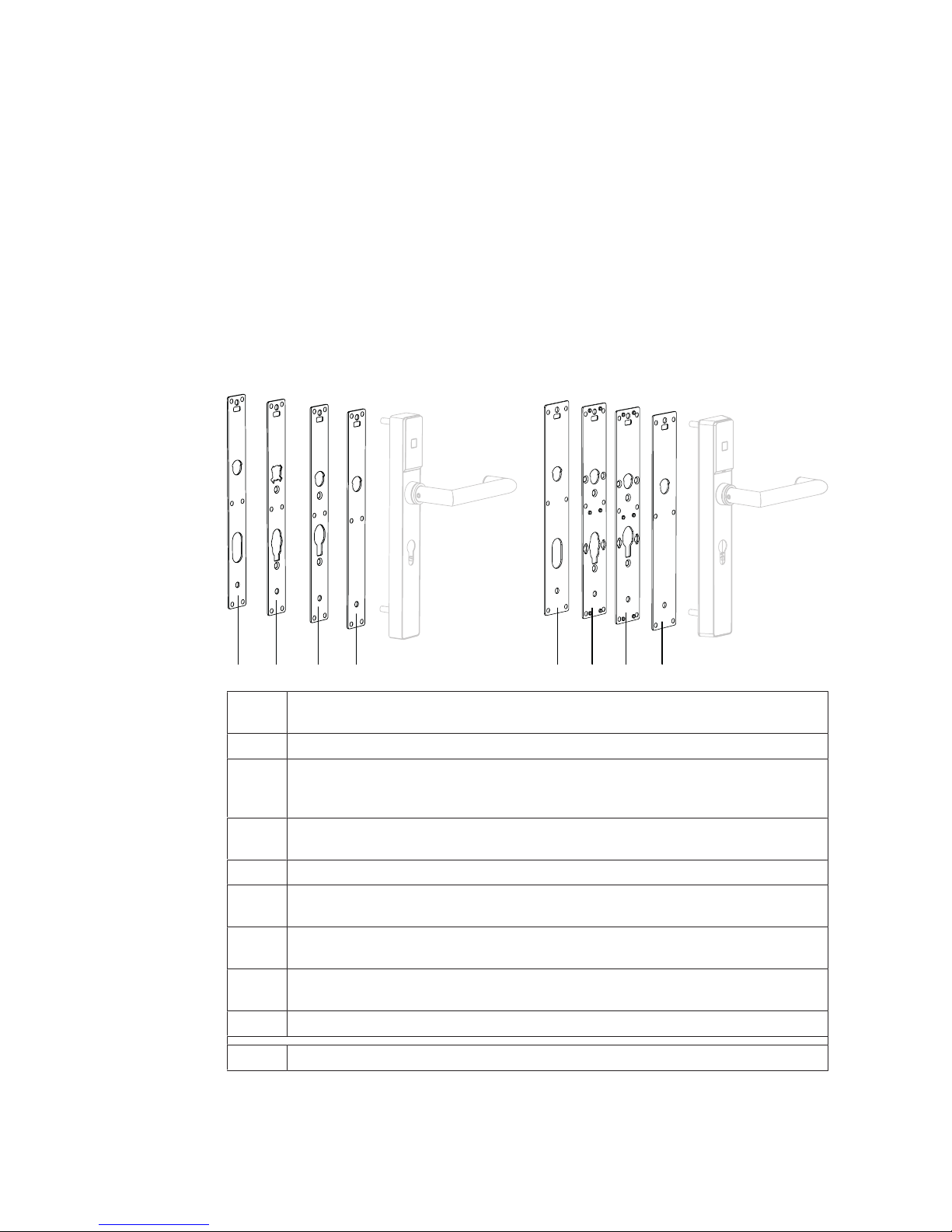
Overview of cylinder support
(Option)
1 2 3 4
Item Cylinder support
Profile Hole spacing, centre distance
(mm)
1 RZ 72, 78
2 RZ 74, 94
2 PZ 70, 78, 85, 90
4* PZ 72, 88, 92
* *Version described in this document
Page 16
Product description Technical Manual
16 HAC Standard fixing - 02/2018dormakaba c-lever pro
3.4 Technical data
Data transfer
RFID
TouchGo c-lever E310 ver-
sion:
RCID and RFID
TouchGo c-lever E110 ver-
sion:
RCID (no RFID)
Body
Lever handle Stainless steel
Frame Zinc
Cover Stainless steel
Antenna cover Synthetic material
Power supply
Batteries 1.5V, AA lithium
Ambient conditions
1
Protection type External fitting IP55
Internal fitting IP40
Temperature External fitting -25°C – +70°C
Internal fitting -0°C – +50°C
The temperature range can
be reduced based on the specification of the batteries
used.
Humidity 0%–95% rH, non-condensing
Climate Unsuitable for use in highly
corrosive atmospheres
(chlorine, ammonia).
Rooms Not to be used in environ-
ments where there is a risk
of explosion.
Media technology
RFID LEGIC advant
prime
MIFARE DESFire
classic
TouchGo c-lever version: RCID
Standards
Fire protection DIN 18273 tested in accord-
ance with EN 1634-1
EI290-C
DO 20.31
EN179 According to test certificate:1 0432 - BPR - 0061 (Kaba);
1
0432 - BPR - 0003 (BKS);
0432 - BPR - 0005 (Dorma)
Protection class EN 1906 class 0
1
EN1906 class 2 for ES1 - TBD
Page 17
Product descriptionTechnical Manual
17HAC Standard fixing - 02/2018 dormakaba c-lever pro
1
In accordance with
DIN18257
1
WB2 in accordance with
B5351
Austria
Usage class EN1906 class 4
Cycles
Battery life at 20°C approx. 150,000 cycles (con-
figuration: whitelist without
acoustic signal)
The configuration influences
the battery life
¹ Certification not yet complete.
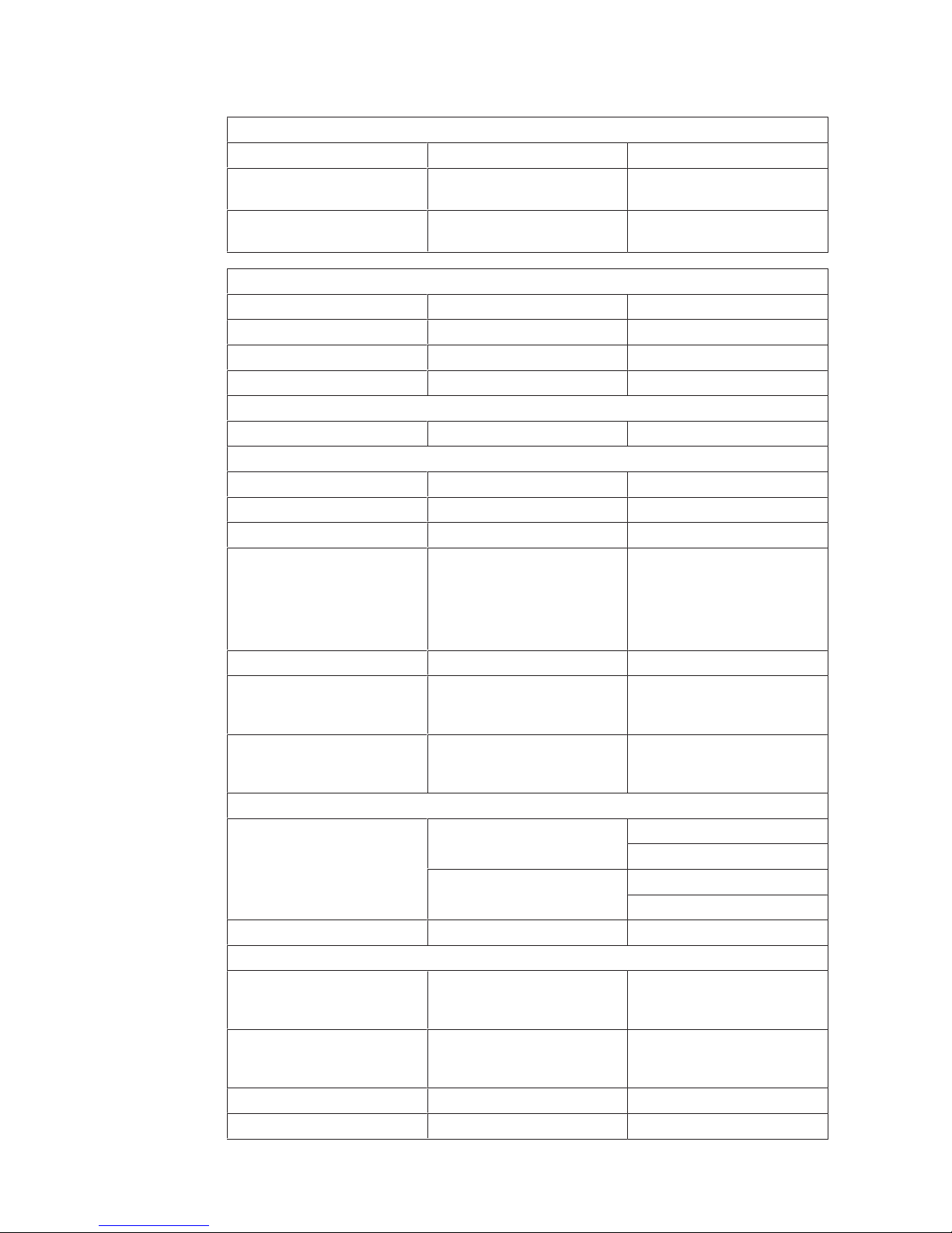
3.4.1 Dimensions
102
91162
298
LM
4025
Ø 8
Ø 8
M5
21
21,1
21,1
21,1
21,1
±42°
±42°
102
91162
298
LM
5425
Ø 8
Ø 8
M5
21
Page 18

Product description Technical Manual
18 HAC Standard fixing - 02/2018dormakaba c-lever pro
3.4.2 Conformity
This product conforms to the EU directives
2014/53/EU Radio Equipment Directive
2011/65/EU RoHS Directive
You can download the original declaration of conformity in PDF format at www.kaba.com/con-
formity.
Page 19
InstallationTechnical Manual
19HAC Standard fixing - 02/2018 dormakaba c-lever pro
4 Installation
This chapter describes the installation of the product.
4.1 Installation requirements
4.1.1 General
An accurate installation of all components is a basic requirement for a properly functioning
device. The following installation instructions must be adhered to.
4.1.2 Door thickness
Requirements
• Minimum door thickness: 38mm
• Maximum door thickness: 100mm
See also section Determining screw length.
4.1.3 Mortise lock
• Make sure that a mortise lock with key-operated latch function is used.
Mortise locks with key-operated latch function enable mechanical opening via the locking
cylinder.
4.2 Replace c-lever with c-lever pro
Replacement plate
• If the c-lever being replaced in the upper area leaves marks on the door, a replacement
plate can be used.
Thickness of the replacement plate: 1.5 mm
Check whether the existing locking cylinder can be used
• Measure dimension A on the c-lever being replaced (inner and outer side).
A
• A = 23.3mm: The existing locking cylinder can be used.
Page 20
Installation Technical Manual
20 HAC Standard fixing - 02/2018dormakaba c-lever pro
• A = 18.3mm: Measure cylinder standoff B on the c-lever being replaced and compare it
with the minimum dimension in the table.
A AB
B
c-lever pro
Without replacement plate With replacement plate
Minimum
cylinder standoff B: 2.7 mm* 4.2 mm*
• If the measured cylinder standoff B is less than the *minimum dimension of the inside or
outside, the locking cylinder must be replaced.
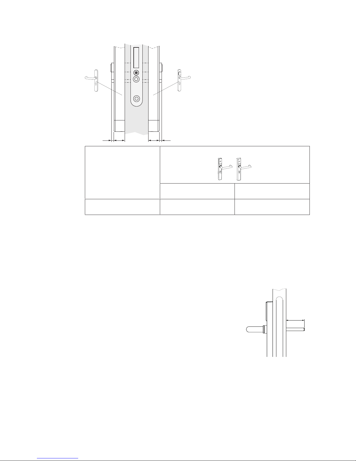
4.3 Spindle standoff
• The door thickness, backplates and lever handle type must be taken into account when
determining the length of the spindle.
Lever handle type “A” spindle standoff mm
HA 46 – 70
A
HB 46 – 63
HC, HO, HQ 46 – 50
HD 46 – 71
HL 46 – 92
HM 46 – 68
HN 46 – 85
HP 46 – 72
KD 46 – 46
KD angled 46 – 56
4.4 Drilling fixing holes
(Only for standard fixing)
Page 21
InstallationTechnical Manual
21HAC Standard fixing - 02/2018 dormakaba c-lever pro
4.4.1 With drill jig / door side 1
NOTICE
The integrated mortise lock may be damaged or destroyed.
To avoid damage, remove the lock from the mortise before drilling.
ü Existing fitting is removed
ü Mortise lock is installed
1. Position the drill jig with guide pin for cylinder (without mount) on the door from the outside.
2. Insert the pin for the spindle through the lock hub.
3. Fasten the drill jig to the door with a C-clamp.
ð The drill jig is connected securely to the door leaf.
4. Remove the guide pin for the cylinder and the pin for the spindle.
5. Remove the mortise lock.
6. Note: Do not drill through the door.
Drill the fastening hole Ø13mm up to the lock mortise.
ø9 mm
ø13 mm
7. Drill the fastening hole Ø9mm up to the lock mortise.
8. Remove the drill jig and C-clamp.
9. Clean the lock mortise.
10. Insert the mortise lock.
Page 22
Installation Technical Manual
22 HAC Standard fixing - 02/2018dormakaba c-lever pro
4.4.2 With drill jig / door side 2
NOTICE
The integrated mortise lock may be damaged or destroyed.
To avoid damage, remove the lock from the mortise before drilling.
ü Mortise lock installed
1. Position the drill jig with guide pin for cylinder on the door.
2. Insert the pin for the spindle through the lock hub.
3. Fasten the drill jig to the door with a C-clamp.
ð The drill jig is connected securely to the door leaf.
4. Remove the guide pin for the cylinder and the pin for the spindle.
5. Remove the mortise lock.
6. Drill the fastening hole Ø13mm up to the lock mortise.
ø9 mm
ø13 mm
7. Drill the fastening hole Ø9mm up to the lock mortise.
8. Remove the drill jig and C-clamp.
9. Clean the lock mortise.
10. Insert the mortise lock.
Page 23
InstallationTechnical Manual
23HAC Standard fixing - 02/2018 dormakaba c-lever pro
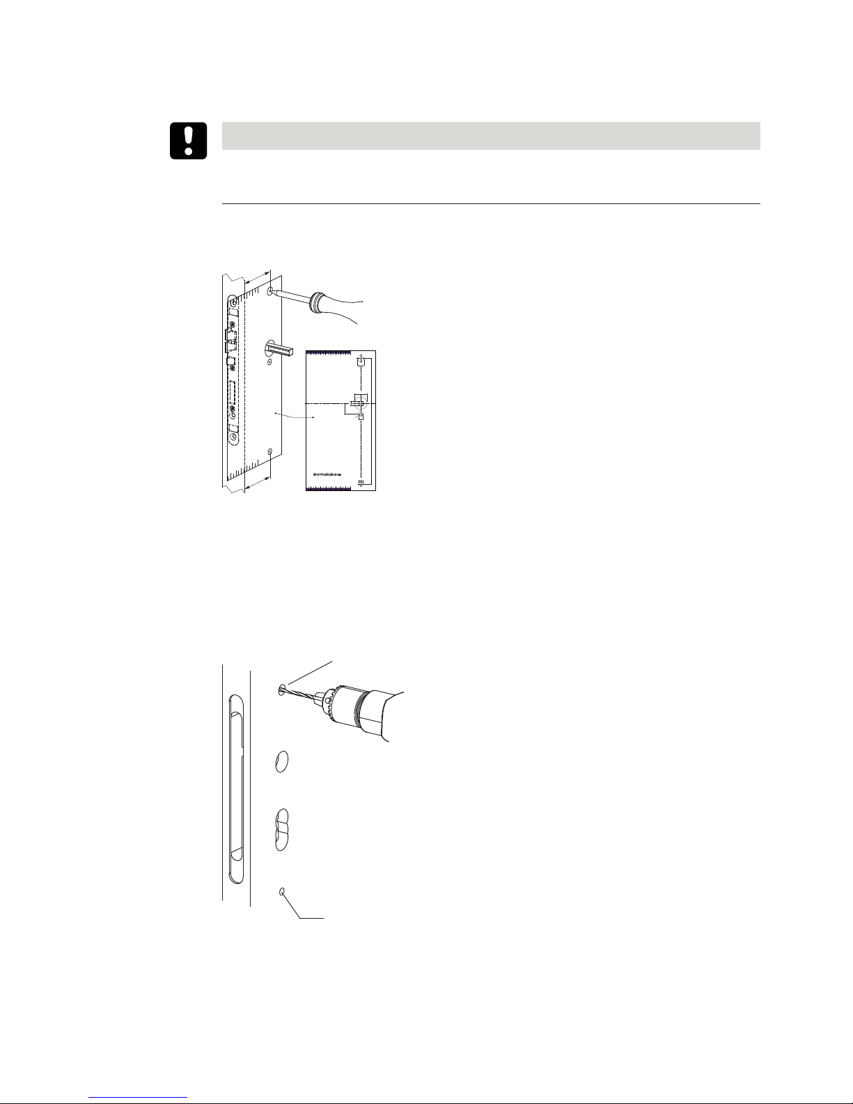
4.4.3 With drilling template / door side 1
NOTICE
The integrated mortise lock may be damaged or destroyed.
To avoid damage, remove the lock from the mortise before drilling.
ü Existing fitting removed
ü Mortise lock installed
A = B
A
B
Handle axis
c-lever pro
c-lever
Option ES1
21,5
162 89,5
8
ø25
[mm]
ø9
ø9
ø13
Bohrschablone c-lever pro, Version HAC
11.2016 1220020104
100 90 80 70 60 50 40 30 20
100 90 80 70 60 50 40 30 20
1. Place the spindle through the lock hub.
2. Position the drilling template over the spindle and align it parallel to the forend.
3. Mark the drill holes.
ð Drill holes for the fastening holes are marked on the door leaf.
4. Remove the mortise lock.
5. Note: Do not drill through the door.
Drill the fastening hole Ø13mm up to the lock mortise.
ø13 mm
ø9 mm
6. Drill the fastening hole Ø9mm up to the lock mortise.
7. Clean the lock mortise.
8. Insert the mortise lock.
Page 24

Installation Technical Manual
24 HAC Standard fixing - 02/2018dormakaba c-lever pro
4.4.4 With drilling template / door side 2
NOTICE
The integrated mortise lock may be damaged or destroyed.
To avoid damage, remove the lock from the mortise before drilling.
ü Existing fitting removed
ü Mortise lock installed
A = B
A
B
21,5
Handle axis
c-lever
c-lever pro
Option ES1
162 89,5
8
ø25
[mm]
ø9
ø9
ø13
20 30 40 50 60 70 80 90 100
20 30 40 50 60 70 80 90 100
1. Place the spindle through the lock hub.
2. Position the drilling template over the spindle and align it parallel to the forend.
3. Mark the drill holes.
ð Drill holes for the fastening holes are marked on the door leaf.
4. Remove the mortise lock.
5. Drill the fastening hole Ø13mm up to the lock mortise.
ø13 mm
ø9 mm
6. Drill the fastening hole Ø9mm up to the lock mortise.
7. Clean the lock mortise.
8. Insert the mortise lock.
ð The fastening holes for the fitting are drilled on both sides of the door.
Page 25

InstallationTechnical Manual
25HAC Standard fixing - 02/2018 dormakaba c-lever pro
4.5 Installing the cylinder support
(Option)
The hole spacing and the cylinder profile determine the cylinder support to be used. See
Product description.
Requirements
• The external fitting is not installed.
• The multitool is available.
• The cylinder support is present.
4.5.1 Removing the backplate, swivelling the cover out
• Remove the backplate of the external fitting (1.).
2.
3.
4.
5.
1.
NOTICE
Damage to the union nut
When loosening the union nut and pushing it aside, make sure that it does not touch the
threaded pin.
• Using the multitool, fully loosen the union nut of the internal fitting.
• Slide the union nut in the direction of the lever handle (2.).
• Make sure that the cover of the antenna is not scratched by the subsequent actions.
• Push the cover at the bottom out of the groove (3.), pull it forwards slightly (4.) and swivel
it out (5.).
Page 26

Installation Technical Manual
26 HAC Standard fixing - 02/2018dormakaba c-lever pro
4.5.2 Inserting the cylinder support
• Place the external fitting on a base.
• Position the cylinder support in the frame as shown (1. - 2.).
1.
2.3.
• Swivel the cylinder support into the frame (3.).
Page 27

InstallationTechnical Manual
27HAC Standard fixing - 02/2018 dormakaba c-lever pro
4.5.3 Positioning the cylinder support
The cylinder support can be used for various hole spacings. The desired hole spacing is set with
the aid of the engraved hole spacing figures (1).
1
Procedure
• With one hand, hold the internal fitting and the cylinder support and rotate them so that
the marked hole spacings are visible.
• Lift the cylinder support slightly (1.), move it (2.) and insert it into the lug (blue) at the desired position (3.).
2.
1.
3.
3.
Example for a hole spacing of 88 mm:
4.5.4 Fitting the cover
• Make sure that the cover of the antenna is not scratched by the subsequent actions.
• Align the cover (1.).
Page 28

Installation Technical Manual
28 HAC Standard fixing - 02/2018dormakaba c-lever pro
• Move the cover as shown (2.), press it against the frame (3.) and at the same time insert
it into the groove (4.).
1.
2.
4.
3.
5.
6.
NOTICE
Damage to the union nut
When moving and tightening the union nut, make sure that it does not touch the threaded
pin.
• Slide the union nut in the direction of the frame.
• Tighten the union nut using the multitool.
Page 29

InstallationTechnical Manual
29HAC Standard fixing - 02/2018 dormakaba c-lever pro
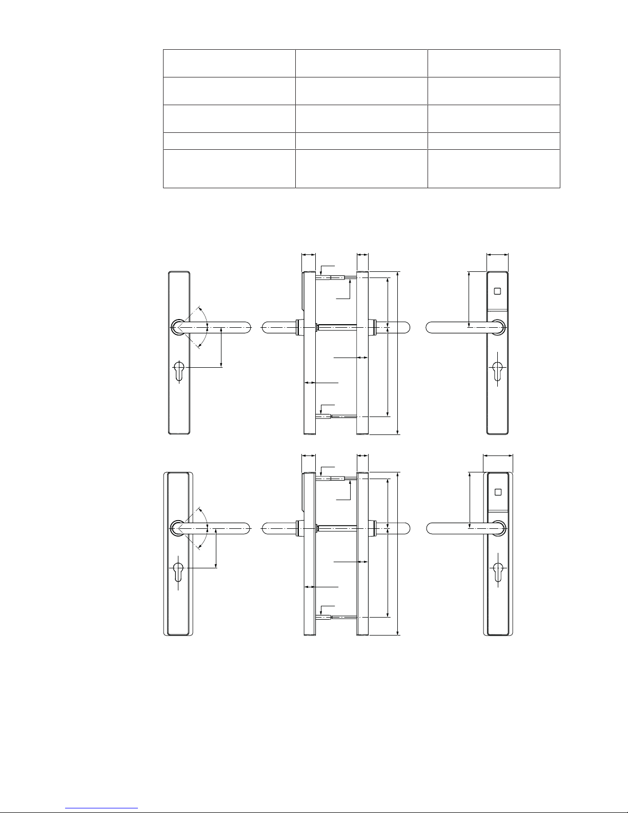
4.6 Preparing the external fitting
1. Remove the backplate.
2. Loosen the pin screw on the lever handle.
3. Align the lever handle.
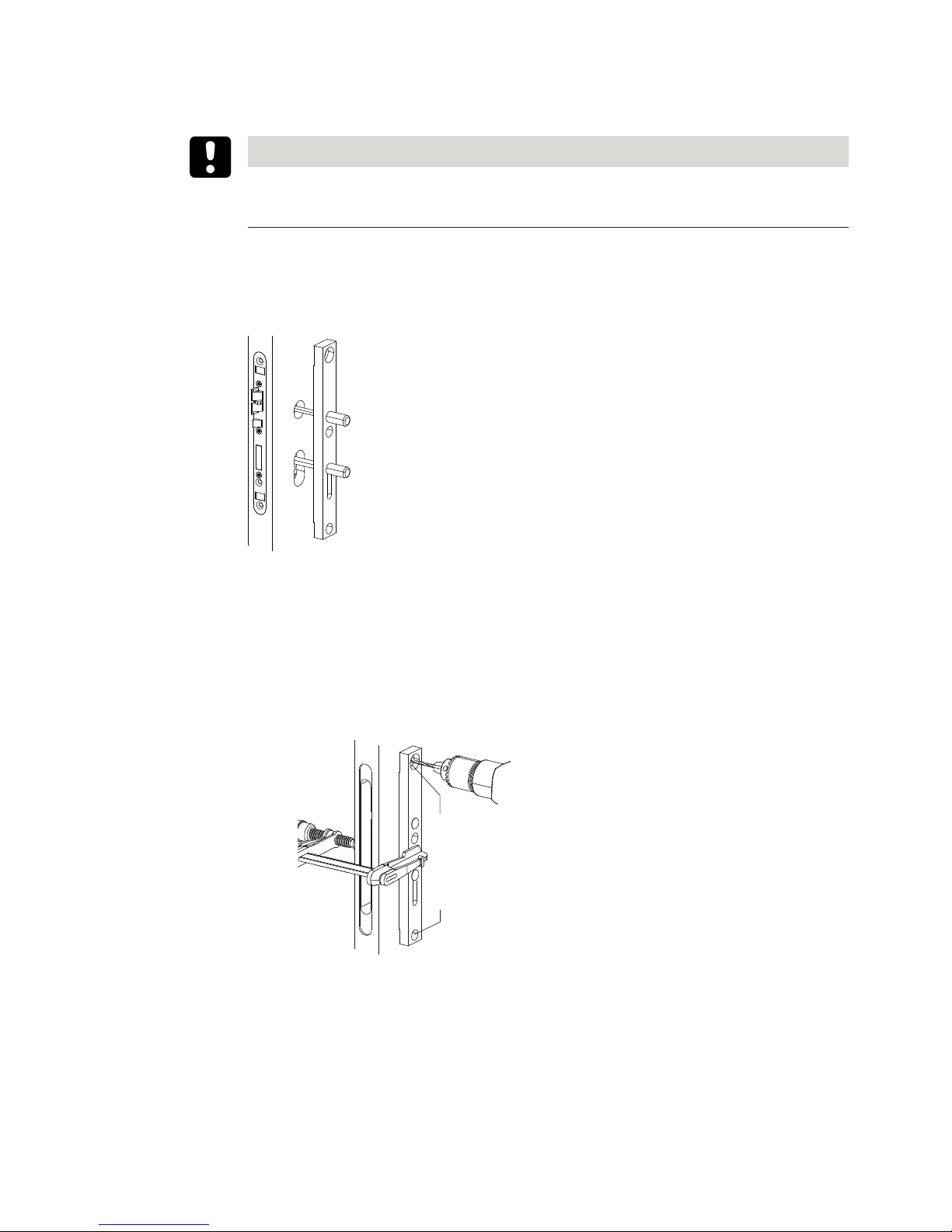
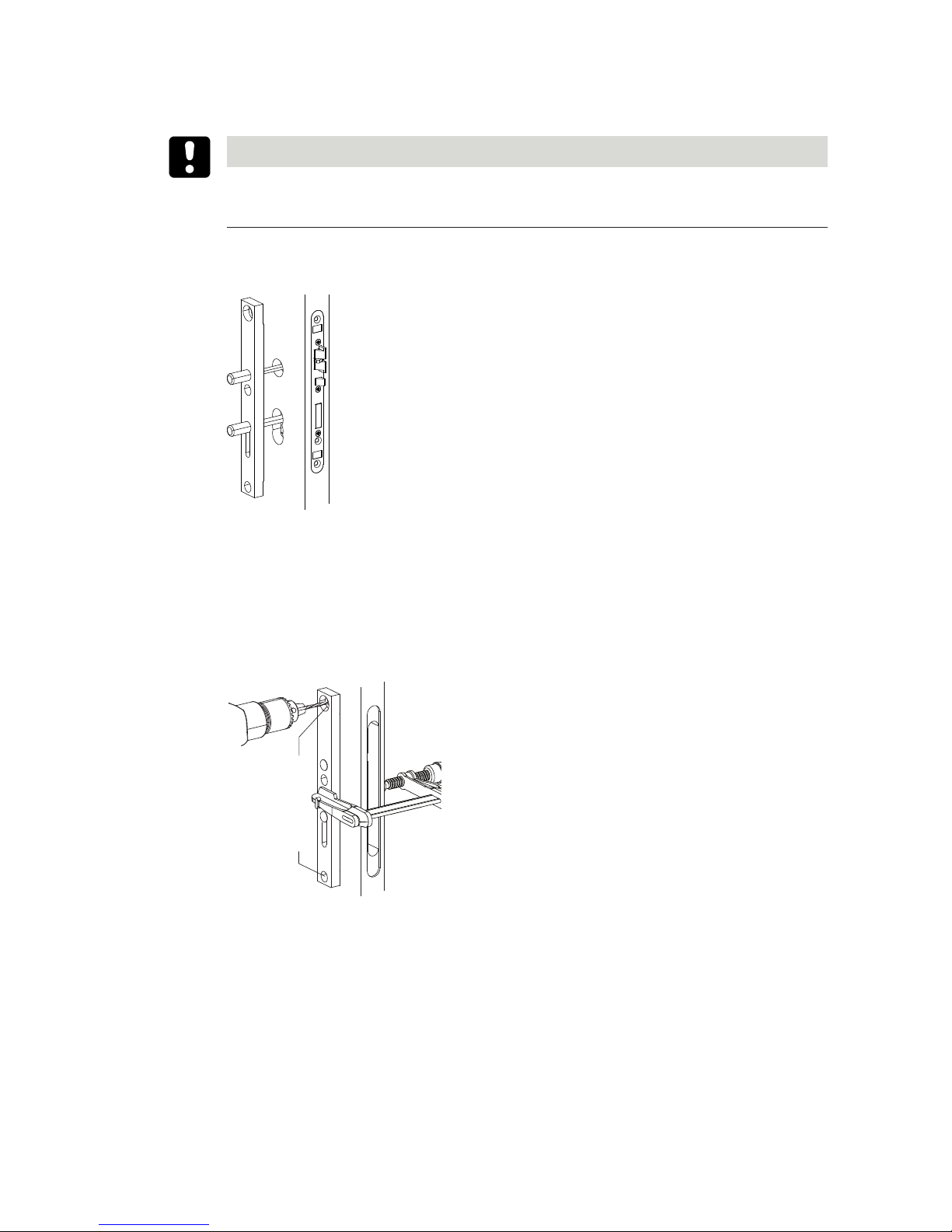
4.7 Insert direction pin and spindle
Variant ‘Outside lever handle turns left’ Variant ‘Outside lever handle turns
right’
1.
2.
3.
1.
2.
3.
1. Align the direction pin as per the figure. 1. Align the direction pin as per the figure.
2. Turn the spindle to the right as far as it
will go and hold in this position.
2. Turn the spindle to the left as far as it
will go and hold in this position.
3. Insert the direction pin. 3. Insert the direction pin.
4. Align the spindle according to the lever
handle direction and insert it into the
coupling unit.
4. Align the spindle according to the lever
handle direction and insert it into the
coupling unit.
Page 30

Installation Technical Manual
30 HAC Standard fixing - 02/2018dormakaba c-lever pro
!
4.
!
!
**
!
!!
4.
!
4.
!
!
!
!
**
4.
5. Screw the spindle in place with the
threaded pin.
5. Screw the spindle in place with the
threaded pin.
** TouchGo option: Ensure that there is no groove present on the side of the spindle marked
with **.
Page 31

InstallationTechnical Manual
31HAC Standard fixing - 02/2018 dormakaba c-lever pro
4.8 Inserting and connecting the coupling unit
NOTICE
There is a risk of crushing or shearing injuries from cables as a result of improper installation
or routing.
Ensure that the cables are routed in such a way that there is no risk of crushing or shearing injuries.
NOTICE
Danger of damage to electronic components from electrostatic discharge.
If electronic printed circuit boards and components are handled incorrectly, damage may occur which leads to their complete breakdown or sporadic faults.
• When installing and repairing the product, the general ESD protective measures are to be
observed.
• Guide the spindle into the square of the outside lever handle and insert the coupling unit
into the external fitting.
TouchGo: Maximum torque: 1.0Nm
• Press the coupling unit lightly against the lever handle and at the same time screw the
threaded pin of the outside lever handle into place.
The coupling unit is installed and secured in the external fitting.
• Insert the coupling unit plug into the white socket (1.).
1.
2.
• Insert the antenna cable into the black socket (2.).
Page 32

Installation Technical Manual
32 HAC Standard fixing - 02/2018dormakaba c-lever pro
• Guide the antenna cable through the backplate.
• Attach the backplate.
Page 33

InstallationTechnical Manual
33HAC Standard fixing - 02/2018 dormakaba c-lever pro
4.9 Installing the external fitting
NOTICE
There is a risk of crushing or shearing injuries from cables as a result of improper installation
or routing.
Ensure that the cables are routed in such a way that there is no risk of crushing or shearing injuries.
NOTICE
Danger of damage to electronic components from electrostatic discharge.
If electronic printed circuit boards and components are handled incorrectly, damage may occur which leads to their complete breakdown or sporadic faults.
• When installing and repairing the product, the general ESD protective measures are to be
observed.
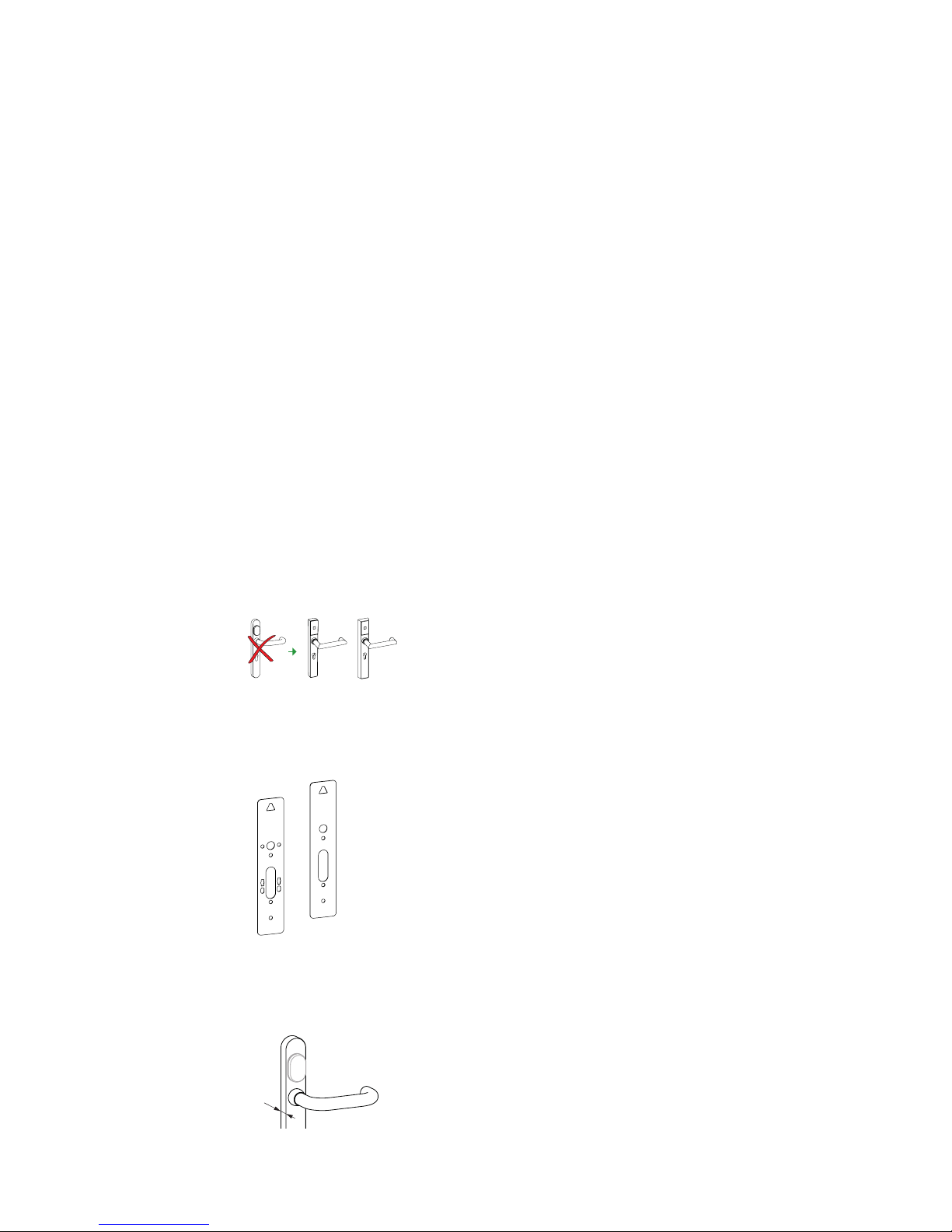
4.9.1 Standard fixing
HAC version (lever handle above the cylinder)
Requirements
• The existing fitting is removed
• The drill holes are present
• The mortise lock is installed
• If present, the locking cylinder is inserted into the mortise lock and the forend locking stud
is screwed in, but has not yet been fully tightened
Procedure
1.
2.
2.
• Guide the antenna cable through the fixing hole in the door (1.).
• Place the external fitting on the outside of the door (2.).
-> The external fitting is inserted into the door but not yet secured.
Page 34

Installation Technical Manual
34 HAC Standard fixing - 02/2018dormakaba c-lever pro
4.10 Determining screw length
The internal and external fittings are screwed together.
If necessary, the screws are extended with elongations.
• Determine the screw length and the number of elongations using the table.
Clamping length* (mm) Screw length
M5 x
Number of
elongations
from to
38 54 40 mm 54 64 50 mm 64 72 60 mm -
72 80 40 mm 1
80 90 50 mm 1
90 100 60 mm 1
*Clamping length = door thickness + thickness of the replacement plate(s)
Page 35

InstallationTechnical Manual
35HAC Standard fixing - 02/2018 dormakaba c-lever pro
4.11 Preparing the internal fitting
NOTICE
Damage to the union nut
When loosening the union nut, make sure it does not touch the threaded pin.
• Using the multitool, loosen the union nut from the internal fitting (>360°).
>360°
• With locking cylinder: If necessary, loosen the forend locking stud.
• Push the cover out of the groove (1), pull it forwards slightly (2) and turn (3).
1.
2.
3.
If the c-lever pro is already programmed, the clock settings are lost approx. 45 seconds after
the battery is removed.
• Push the battery holder in the direction shown (1.) and at the same time swivel it forwards (2.).
1.
2.
Page 36

Installation Technical Manual
36 HAC Standard fixing - 02/2018dormakaba c-lever pro
• Align the lever handle.
Page 37

InstallationTechnical Manual
37HAC Standard fixing - 02/2018 dormakaba c-lever pro
4.12 Installing the internal fitting
NOTICE
Danger of damage to electronic components from electrostatic discharge.
If electronic printed circuit boards and components are handled incorrectly, damage may occur which leads to their complete breakdown or sporadic faults.
• When installing and repairing the product, the general ESD protective measures are to be
observed.
NOTICE
There is a risk of crushing or shearing injuries from cables as a result of improper installation
or routing.
Ensure that the cables are routed in such a way that there is no risk of crushing or shearing injuries.
4.12.1 c-lever standard variant
Prerequisites
• The drill holes are present
• The external fitting has been placed on the door
• The antenna cable has been guided to the inside of the door
• The mortise lock is installed
• With locking cylinder: The locking cylinder is inserted into the mortise lock and the forend
locking stud is screwed in but has not yet been fully tightened.
Procedure
• Guide the antenna cable through the internal fitting (1).
1.
2.
• Place the internal fitting onto the spindle (and the locking cylinder) (2).
• Place the special washers onto the screws.
• Align the external fitting and screw it in place (maximum torque: 2.5±0.5 Nm).
Page 38

Installation Technical Manual
38 HAC Standard fixing - 02/2018dormakaba c-lever pro
• Insert the antenna cable.
Inserting the battery holder
• Insert the battery holder (1), push it towards the lever handle (2) and at the same time
swivel it into the frame (3).
1.
2.
3.
• If present: Remove the contact protection film.
Installing the cover
• Align the cover (1).
• Move the cover in the sequence shown (2–3) and insert it into the groove (4).
-> The cover protrudes on the side opposite the groove.
• Press the protruding cover against the frame (5) and hold down.
1.
2.
3.
4.
5.
• Tighten the union nut using the multitool.
• Let go of the cover.
• Tighten the threaded pin on the lever handle. Option TouchGo: Maximum torque: 1.0 Nm
• Tighten the forend locking stud.
• Carry out a function check; see Operation [}6].
Page 39

InstallationTechnical Manual
39HAC Standard fixing - 02/2018 dormakaba c-lever pro
• Remove the protective film on the external fitting.
Page 40

Installation Technical Manual
40 HAC Standard fixing - 02/2018dormakaba c-lever pro
4.13 Checking the installation
Carry out the following checks after the installation and after service and maintenance activities:
• Make sure that the device and the mortise lock have been correctly installed mechanically.
• Make sure that the device and the mortise lock are working properly.
• After programming: Carry out a function check, see Operation [}6].
Page 41

InstallationTechnical Manual
41HAC Standard fixing - 02/2018 dormakaba c-lever pro
4.14 Dismantling
4.14.1 Disassembling the internal fitting
NOTICE
Damage to the union nut
When loosening the union nut, make sure it does not touch the threaded pin.
• Using the multitool, loosen the union nut from the internal fitting (>360°).
>360°
• With locking cylinder: If necessary, loosen the forend locking stud.
• Push the cover out of the groove (1), pull it forwards slightly (2) and turn (3).
1.
2.
3.
• Push the battery holder in the direction shown (1.) and at the same time swivel it forwards (2.).
1.
2.
• Unplug the antenna cable.
Page 42

Installation Technical Manual
42 HAC Standard fixing - 02/2018dormakaba c-lever pro
NOTICE
Improper disassembly may lead to a risk of pinching or shearing of cables.
Remove the cables in such a way that there is no risk of pinching or shearing.
• Loosen the screws and remove them along with the special washers.
• Remove the internal fitting from the spindle (and locking cylinder).
The internal fitting is dismantled.
Page 43

InstallationTechnical Manual
43HAC Standard fixing - 02/2018 dormakaba c-lever pro
4.14.2 Disassembling the external fitting
NOTICE
There is a risk of crushing or shearing injuries from cables as a result of improper installation
or routing.
Ensure that the cables are routed in such a way that there is no risk of crushing or shearing injuries.
• Remove the external fitting from the door (1) and at the same time guide the antenna
cable through the fixing hole in the door (2).
2.
1.
4.
3.
• Remove the backplate (3).
• Pull the antenna cable out of the backplate (4).
Remove coupling
• Pull the coupling unit plug out of the white socket (1).
1.
2.
• Remove the antenna cable from the black socket (2).
• Loosen the threaded pin in the outside lever handle.
• Remove the coupling unit from the external fitting.
• Loosen the threaded pin and remove the spindle.
Page 44

Programming Technical Manual
44 HAC Standard fixing - 02/2018dormakaba c-lever pro
5 Programming
This section describes how to program the components.
This chapter describes how to program the components using the master and user media.
Wireless components require wireless commissioning before being used for the first time. A
description can be found in the wireless documentation.
Further information about programming can be found in the manuals for the system soft-
ware used.
5.1 Programming TouchGo products
Programming TouchGo products with RCID
Products with RCID Firmware Transmission technology
c-lever proTouchGo E310 RCID and RFID
c-lever proTouchGo E110 RCID
See: dormakaba c-lever TouchGo operating instructions
Programming TouchGo products with RFID
Products with RFID Firmware Transmission technology
c-lever proTouchGo E310 RCID and RFID
See next Chapter.
5.2 Initial programming of MRD components
When first used, multi-RFID (MRD) components are set to the technology in which the components are used with a master LEGIC or MIFARE. The components then behave as defined
for the authorisation types LEGIC (LEA) or MIFARE (MID).
Note: After an INI reset using master media, the components must then be re-programmed
using a master LEGIC or MIFARE.
5.3 Master media
With the A master and B master media, the components are programmed directly. The B
masters are organised under an A master. The master media do not have any access authorisations.
5.4 User media
All User media are organised under a B master.
Page 45

ProgrammingTechnical Manual
45HAC Standard fixing - 02/2018 dormakaba c-lever pro
NOTICE
Lost User media should be immediately blocked and deleted from all components.
(Delete lost User media in the system software in the whitelist (add CardLink to the blacklist)
or delete all User media with the corresponding master and then re-program all User media).
Page 46

Programming Technical Manual
46 HAC Standard fixing - 02/2018dormakaba c-lever pro
5.5 Program structures
All components can be organised manually in an A/B structure or in a B structure.
In the A/B structure, up to 200 B masters can be created with one A master. The User media
cannot be directly programmed in an A structure.
Separate access authorisations to User media can be issued with each B master. User media
can be programmed with different B masters but not with the same components.
Each component can be programmed with up to 4000 User media. These can be distributed
across the various B masters as required. For example, a B1 master only manages 50 users
whilst another master, B2, manages up to 3950 users.
5.6 A/B and B structures
A structure Master A
Master B
User media
B structure
Master B
User media
Page 47

ProgrammingTechnical Manual
47HAC Standard fixing - 02/2018 dormakaba c-lever pro
5.7 Programming user media with B masters
In this case, the light ring glows green for as long as the medium is located within the antenna
field and is read.
Programming the
User media
Action
1
1 s
Beep
Launch programming mode:
Master B approx. 1 s hold in front
of the antenna.
1 x short
2
1 s
Beep
Program User media:
User media approx. 1 s hold in front
of the antenna.
1 x short
3
1 s
Beep
Additional User media approx. 1 s
hold in front of the antenna.
1 x short
4
Beeeep
1 s
To complete:
Master B approx. 1 shold in front of
the antenna.
Note: If no master medium is held
up within 20 seconds, programming mode ends automatically and
one long acoustic signal sounds.
1 x long
Page 48

Programming Technical Manual
48 HAC Standard fixing - 02/2018dormakaba c-lever pro
5.8 Deleting individual user media
In this case, the light ring glows green for as long as the medium is located within the antenna
field and is read.
Deleting
User media
Action
1
1 s
Beep
Launch programming mode:
Master B approx. 1 s hold in front
of the antenna.
1 x short
3 s
2
Beep
Beep
Delete User media:
User media approx. 3 s hold in front
of the antenna.
2 x short
3
Beeeep
1 s
To complete:
Master B approx. 1 shold in front of
the antenna.
Note: If no master medium is held
up within 20 seconds, programming mode ends automatically and
one long acoustic signal sounds.
1 x long
Page 49

ProgrammingTechnical Manual
49HAC Standard fixing - 02/2018 dormakaba c-lever pro
5.9 Deleting individual Master Bs
Consequences
• The Master-B programmed under Master-A is deleted.
• All user media programmed under Master-B are deleted.
Procedure
1
1 s
Beep
Activate programming mode:
Hold Master A in front of the an-
tenna briefly (approx. 1s).
1 short signal sounds.
1 x short
10 s
2
Beep
Beep
Remove Master-B and all user media from the component:
Hold Master-B in front of the antenna until two short signals sound.
(Green illuminates for as long as
Master-B is in the antenna field
and is being read.)
2 x short
3
Beeeep
1 s
Disable programming mode:
Hold Master A in front of the an-
tenna briefly (approx. 1s).
1 long signal sounds.
Note: If no master medium is held
up, programming mode is deactivated after 20s and one long signal
sounds.
Changes were implemented.
1 x long
Page 50

Programming Technical Manual
50 HAC Standard fixing - 02/2018dormakaba c-lever pro
5.10 Deleting all user media
Components should not be in programming mode.
In this case, the light ring glows green for as long as the medium is located within the antenna
field and is read.
Deleting
user media
Action
10 s
1
Beep
Beep
hold in front of the antenna. Master B approx. 10 s
All User media under the Master B
are deleted.
2 x short
1 x long
1
1 x short
Key:
1
Firmware version 42xx
Page 51

ProgrammingTechnical Manual
51HAC Standard fixing - 02/2018 dormakaba c-lever pro
5.11 INI reset with master media for whitelist and CardLink™
An INI reset can be used to restore the factory settings for the components.
NOTICE
All User media and master media as well as the traceback are deleted.
Components should not be in programming mode.
INI reset for whitelist
In this case, the light ring glows green for as long as the medium is located within the antenna
field and is read.
INI reset with master Action
15 s
1
Beep
Beep
Master B structure
Master B approx. 15 s hold in front
of the antenna. The INI reset will be
executed after 15 s.
After 10 s,
1 x long,
1 x short,
after 15 s,
2 x short
15 s
1
Beep
Beep
Master A/B structure
Master A approx. 15 s hold in front
of the antenna. The INI reset will be
executed after 15 s.
After 10 s,
1 x long,
1 x short,
after 15 s,
2 x short
Page 52

Programming Technical Manual
52 HAC Standard fixing - 02/2018dormakaba c-lever pro
INI reset for CardLink
In this case, the light ring glows green for as long as the medium is located within the antenna
field and is read.
INI reset with master Action
15 s
1
Beep
Beep
B master
Master B approx. 15 s hold in front
of the antenna. The INI reset will be
executed after 15 s.
2 x short
15 s
1
Beep
Beep
Master A
Master A approx. 15 s hold in front
of the antenna. The INI reset will be
executed after 15 s.
2 x short
Page 53

OperationTechnical Manual
53HAC Standard fixing - 02/2018 dormakaba c-lever pro
6 Operation
This section describes operation of the product.
6.1 Operating TouchGo products
Operating TouchGo products with RCID
Products with RCID Firmware Data transmission used
TouchGo c-lever pro E310 RCID
TouchGo c-lever pro E110 RCID
See: dormakaba c-lever TouchGo operating instructions
Operating TouchGo products with RFID
Products with RFID Firmware Data transmission used
TouchGo c-lever pro E310 RFID
See next Chapter.
6.2 Opening with user media
Before being used for the first time, access authorisations for the relevant system software
must be transmitted to the User media.
2
1
2
Beep
1. Hold authorised user medium in front of the antenna of the
fitting.
-> The acoustic and visual signals1 confirm access authorisation.
Note: The c-lever's opening time is limited; after this time has
elapsed, the c-lever closes automatically. Upon delivery, the opening
time is approx. 6 s, but this can be adjusted using the 1460 programmer or the system software.
2. Activate the lock by pushing the lever handle.
3. The door can be opened.
Page 54

Operation Technical Manual
54 HAC Standard fixing - 02/2018dormakaba c-lever pro
Beep
Beep
Beep
Beep
If there is an attempt to gain access using unauthorised user media,
the acoustic1 signal will sound four times and the red1 light will
briefly flash four times.
Key:
1
If the function(s) have been activated using the programmer 1460 or the system software.
Page 55

MaintenanceTechnical Manual
55HAC Standard fixing - 02/2018 dormakaba c-lever pro
7 Maintenance
This section describes product maintenance.
7.1 Maintenance table
The component's mechanism and/or electronics do not require any maintenance.
NOTICE
Opening the mechatronic unit.
Opening the mechatronic unit releases the manufacturer from any liability under the guarantee.
Components Measures Interval
All components Function check in accordance with instruc-
tions
12 months
Replacing the batteries 24 months
1
Clock (components) Check and set clock time with the system
software
12 months
Firmware update To modify functionality
See the system description
as required
Key:
1
With lithium batteries
7.2 Cleaning
Only disinfection agents that are explicitly formulated for cleaning delicate metal surfaces
and plastics may be used. The use of unsuitable cleaning agents or methods can damage the
components' surface.
1. Use a soft, damp cloth to clean the surface.
Page 56

Service Technical Manual
56 HAC Standard fixing - 02/2018dormakaba c-lever pro
8 Service
8.1 Serial number
The serial number with QR code is located on the backplate of the internal fitting.
8.2 Replacing batteries
Requirement
• 2 new batteries 1.5 V AA lithium are available.
• The multitool is available
NOTICE
Danger of damage to electronic components from electrostatic discharge.
If electronic printed circuit boards and components are handled incorrectly, damage may occur which leads to their complete breakdown or sporadic faults.
• When installing and repairing the product, the general ESD protective measures are to be
observed.
Whilst the battery is being changed, all the data (access authorisations, configurations and
traceback) is retained in the battery-independent memory. The clock settings are lost after 45
seconds.
Procedure
NOTICE
Damage to the union nut
When loosening the union nut, make sure it does not touch the threaded pin.
• Using the multitool, loosen the union nut from the internal fitting (>360°).
>360°
• With locking cylinder: If necessary, loosen the forend locking stud.
• Push the cover out of the groove (1), pull it forwards slightly (2) and turn (3).
Page 57

ServiceTechnical Manual
57HAC Standard fixing - 02/2018 dormakaba c-lever pro
1.
2.
3.
• Push the battery holder in the direction shown (1.) and at the same time swivel it forwards (2.).
1.
2.
• Remove the spent batteries.
• Insert the new batteries, observing the polarity.
• Insert the battery holder (1), push it towards the lever handle (2) and at the same time
swivel it into the frame (3).
1.
2.
3.
• If present: Remove the contact protection film.
Page 58

Service Technical Manual
58 HAC Standard fixing - 02/2018dormakaba c-lever pro
• Align the cover (1).
• Move the cover in the sequence shown (2–3) and insert it into the groove (4).
-> The cover protrudes on the side opposite the groove.
• Press the protruding cover against the frame (5) and hold down.
1.
2.
3.
4.
5.
• Tighten the union nut using the multitool.
• Let go of the cover.
• Carry out a function check, see Operation [}6].
8.3 Replacing the TouchGo media battery
See dormakaba c-lever TouchGo operating instructions
Page 59

ServiceTechnical Manual
59HAC Standard fixing - 02/2018 dormakaba c-lever pro
8.4 Connecting the programmer
• Connect the c-lever and programmer using the programming cable and the adapter
(1355-42B) for the programmer cable (grey).
Page 60

Service Technical Manual
60 HAC Standard fixing - 02/2018dormakaba c-lever pro
8.5 Configuration and traceback
For correct time management, the clock time and the date on the device must be up-to-date.
c-lever pro without wireless module:
Configuration, updates (e.g. of the clock time) and traceback read-outs are performed using
the programmer.
The traceback is transmitted from the programmer to the system software for evaluation.
See also > Programmer
8.6 Reset (INI reset)
Consequences of an INI reset
• All parameter settings and data are deleted and returned to their original values (factory
settings).
• The access point is blocked during the INI reset.
NOTICE
Loss of data
The INI reset deletes all settings and data saved on the device.
A reset can be performed in the following ways:
• With master media
See INI reset with master media for whitelist and CardLink™ [}5.11]
• With programmer 1460, see Reset with programmer 1460
• With tweezers, see Reset using tweezers
Also see about this
2 5.11 INI reset with master media for whitelist and CardLink™ [}51]
8.6.1 Reset with programmer 1460
Requirements
• A programmer 1460 is available.
• An authorised user medium or a master medium is available.
• The batteries are inserted.
8.6.1.1 Connecting the programmer
• Connect the c-lever and programmer using the programming cable and the adapter
(1355-42B) for the programmer cable (grey).
8.6.1.2 Carrying out a reset
• Hold an authorized user medium or master medium in front of the antenna.
• Open the Settings menu on the programmer.
Page 61

ServiceTechnical Manual
61HAC Standard fixing - 02/2018 dormakaba c-lever pro
• Select Actuator.
• Select INI reset.
• Select Yes.
Two signals will sound following a successful reset.
A detailed description can be found in the programmer operating instructions.
Page 62

Service Technical Manual
62 HAC Standard fixing - 02/2018dormakaba c-lever pro
8.6.2 Reset using tweezers
NOTICE
Danger of damage to electronic components from electrostatic discharge.
If electronic printed circuit boards and components are handled incorrectly, damage may occur which leads to their complete breakdown or sporadic faults.
• When installing and repairing the product, the general ESD protective measures are to be
observed.
Requirements
• The multitool is available
• Electrically conductive tweezers are available.
• The batteries are inserted
Procedure
NOTICE
Damage to the union nut
When loosening the union nut, make sure it does not touch the threaded pin.
• Using the multitool, loosen the union nut from the internal fitting (>360°).
>360°
• With locking cylinder: If necessary, loosen the forend locking stud.
• Push the cover out of the groove (1), pull it forwards slightly (2) and turn (3).
Page 63

ServiceTechnical Manual
63HAC Standard fixing - 02/2018 dormakaba c-lever pro
1.
2.
3.
NOTICE
Danger of damage to electronic components from electrostatic discharge.
Damage may occur if electronic printed circuit boards and components are handled incorrectly, which leads to complete breakdown or malfunctions of the device.
• Adhere to and use the general ESD protective measures when handling electronic components.
• Connect the contacts shown here with electrically conductive tweezers for 3 seconds.
Two signals will sound following a successful reset.
• Align the cover (1).
• Move the cover in the sequence shown (2–3) and insert it into the groove (4).
-> The cover protrudes on the side opposite the groove.
• Press the protruding cover against the frame (5) and hold down.
1.
2.
3.
4.
5.
Page 64

Service Technical Manual
64 HAC Standard fixing - 02/2018dormakaba c-lever pro
• Tighten the union nut using the multitool.
• Let go of the cover.
8.7 Firmware update
See Programmer 1460 user manual.
Page 65

ServiceTechnical Manual
65HAC Standard fixing - 02/2018 dormakaba c-lever pro
8.8 Emergency opening
If the battery is ‘Empty’ or the batteries are completely dead, the door can be opened using
an emergency opening.
The emergency opening can be performed in the following ways:
• Lock with latch function:
Open door using the locking cylinder
• Lock without latch function:
See next Chapter.
8.8.1 Opening with an external power supply
The external power supply comes from the battery emergency opening device or the programmer.
Devices with TouchGo option
The external power supply is only possible with the battery emergency opening device.
Prerequisites
• Battery emergency opening device/programmer is present
• Programming cable is available
• Adapter is available for the programming cable
• There is an authorised user medium
• New batteries are available for the device
• The multitool is available
Procedure
• Connect the device and external power supply using the programming cable and the adapter; see Connecting the Programmer chapter.
With battery emergency opening device With programmer
Press the button for approx. 1s on the battery emergency opening device.
On the programmer, select Settings > Emergency Power Supply and follow the instructions.
• Make a booking with the authorised user medium.
The lever handle on the external fitting engages and remains engaged until new batteries
are used.
• Engage the lever handle and open the door.
• Replace the batteries in the device; see ‘Replacing batteries’ chapter.
• Disconnect the device and the external power supply.
• Set the time.
• Carry out a function check; see Operation chapter.
Page 66

Service Technical Manual
66 HAC Standard fixing - 02/2018dormakaba c-lever pro
8.9 Replacing the antenna
NOTICE
Danger of damage to electronic components from electrostatic discharge.
If electronic printed circuit boards and components are handled incorrectly, damage may occur which leads to their complete breakdown or sporadic faults.
• When installing and repairing the product, the general ESD protective measures are to be
observed.
NOTICE
There is a risk of crushing or shearing injuries from cables as a result of improper installation
or routing.
Ensure that the cables are routed in such a way that there is no risk of crushing or shearing injuries.
Remove antenna
• Dismantle the internal fitting. [}4.14.1]
• Dismantle the external fitting (the coupling must not be removed). [}4.14.2]
• Push the two middle clips outwards and at the same time lift the board.
• On one side, push the two clips inwards and at the same time slide the antenna out of the
frame.
Install the antenna
• Place the new antenna with seal into the frame and press against the frame.
You will be able to hear the antenna click into place.
• Remove the protective film.
Page 67

ServiceTechnical Manual
67HAC Standard fixing - 02/2018 dormakaba c-lever pro
Install the antenna board
• Slide the antenna board onto the antenna.
• Press the antenna board against the antenna.
• Ensure that the antenna board snaps into place on the antenna.
• Insert the coupling unit plug into the white socket (1.).
1.
2.
• Insert the antenna cable into the black socket (2.).
• Guide the antenna cable through the backplate.
• Attach the backplate.
• Install the external fitting. [}4.9.1]
• Install the internal fitting. [}4.12.1]
Page 68

Troubleshooting Technical Manual
68 HAC Standard fixing - 02/2018dormakaba c-lever pro
9 Troubleshooting
This chapter provides important information on rectifying product errors.
TouchGo option
TouchGo product error analysis can be found after the next chapter.
9.1 Error analysis
Symptoms Possible causes Measures
The use of a master or user
medium is confirmed via various acoustic and/or visual
signals by the components
1 x very
short
9 x
flashes
red
– Battery "Low"
(V4 from FW 42.XX)
– Replace the batteries
Door does not open: authorisation via an authorised user
medium is confirmed by
acoustic signals
1 x very
long
— – Alarm — Battery "Empty" – Replace the batteries
Door does not open: no response to authorisation via
an authorised user medium
— — – Battery fully discharged
– Component not programmed yet
– Emergency power supply,
replace the batteries
– Program the component
Door does not open: authorisation by an authorised user
medium is confirmed via
acoustic and visual signals
8 x
short
8 x
short
red
– Self-test could not be completed
– Check or replace the coupling unit
Door does not open: authorisation by an authorised user
medium is confirmed via
acoustic and visual signals
4 x
short
4 x
short
red
– Medium not programmed
– Outside the time window
– Program medium
– Check time profiles
Door does not open: authorisation by an authorised user
medium is confirmed via
acoustic and visual signals
1 x long
1 x
short
1 x long
1 x
short
green
– Internal clock in component
has failed
– Check programming and
clock time
User medium cannot be programmed
— — – 4000 media or groups
already programmed in the
e-module
– Faulty medium
– Not the correct technology
– Contact customer service
Master medium cannot be
programmed
1 x
short
1 x red – E-module already pro-
grammed
– Carry out INI reset for emodule
Master medium is not detected
— — – Antenna not connected to
e-module
– No power supply
– Establish connection or
power supply
Other errors 3 x
short
1 x
short
red
1 x
short
green
– Unintentional re-start —
Page 69

TroubleshootingTechnical Manual
69HAC Standard fixing - 02/2018 dormakaba c-lever pro
Symptoms Possible causes Measures
1 x
short
red
Door is always open: the
lever handle on the outside is
always engaged
— — – TimePro function activated
– Faulty coupling unit
– Deactivate TimePro function
– Replace coupling unit
The use of a master or user
medium is not confirmed by
the component
— — – Antenna connection error
or faulty electronics
– Check connection between
antenna and electronics
Door is always open: door
does not open or close at
programmed time
— — – Time is missing on e-mod-
ule or is not correctly set
– Incorrect programming
– Set time, check programming
– Replace coupling unit
Page 70

Troubleshooting Technical Manual
70 HAC Standard fixing - 02/2018dormakaba c-lever pro
9.2 TouchGo applications error analysis
9.2.1 Operation error analysis
Symptoms Signalling Possible causes Measures
Device Medium
Door slow to open 1 x very
long
9 x very
short red
1 x green
(open)
- Battery in the device
is ‘low’
Replace battery
3 x long
then
1 x green
(open)
2 x red
every 10 s
Battery in the medium
is ‘low’
Replace battery
Door cannot be
opened with a medium
4 x short 4 x red - Medium not pro-
grammed
Program medium
1 x very
long
- - Battery in the device
is ‘empty’
Use the emergency opening and replace the
device’s battery
- - - Medium or device battery completely empty
Replace medium and/or
device battery
8 x short 8 x red - Faulty device/coupling Operating the device
again
If the fault recurs, call a
qualified technician and
use the emergency opening.
1 x short 1 x green - Device faulty
Door is always open.
The lever handle on
the outside is permanently engaged.
- - - Device faulty
- - - Device is in Office or
Pass Mode, fault in
device
The lever handle on
the outside engages
accidentally
1 x short 1 x green - Device detects an au-
thorised user medium
Increase distance
between user medium
and device
Page 71

TroubleshootingTechnical Manual
71HAC Standard fixing - 02/2018 dormakaba c-lever pro
9.2.2 Programming error analysis
Symptoms Signalling on the
device
Possible causes Measures
Programming mode
cannot be activated
with Programming
mode
1 x long 1 x red Programming master used
is not the administrator for
the door
Use the programming master
with an administrator right or
Carry out a reset and program
the programming master as
the administrator
- - Device battery or Programming master empty
Replace battery
User medium cannot
be programmed
- - Medium battery empty Replace battery
1 x long Green
perman-
ently, as
long as
medium
in range,
then
1 x red
Maximum number of programmable media reached
Ensure that the number of programmed media has not been
exceeded in the key plan
Page 72

Disposal / dismantling Technical Manual
72 HAC Standard fixing - 02/2018dormakaba c-lever pro
10 Disposal / dismantling
10.1 Decommissioning / dismantling
• Remove or delete the device in the system software.
• Dismantle the device, see Dismantling [}4.14]
• Carry out a reset.
• Remove the battery/batteries.
10.2 Disposal
This product compliance with the WEEE Directive and is labelled with the "crossed-out
wheelie bin" WEEE symbol as German Industrial Standards (DIN) EN 50419.
The symbol indicates that electrical and electronic devices must be returned separately in EU
member states.
You must not dispose of the device in the household waste as per the European WEEE Directive.
The device's integral components must be separated before they are taken for recycling or
disposal. Old and used devices contain valuable recyclable materials which must be recycled.
Toxic and hazardous components may cause long-term damage to the environment if you dispose of them incorrectly.
Legislation (such as the Electrical and Electronic Equipment Act [ElektroG] in Germany) dictates that facility operators are obliged to return electrical and electronic devices to their
manufacturer, point of purchase or designated public collection points at the end of their life
cycle.
Disposal in Germany:
dormakaba EAD GmbH will take responsibility for correct disposal of supplied goods once
they are no longer in use as per statutory regulations (ElektroG in Germany). The owner of
the used electrical appliance bears any costs incurred for transport to the manufacturer's
plant.
Disposal in Switzerland:
the device is to be returned to an electrical appliance return point as per Regulation on Returning, Taking Back and Disposing of Electrical and Electronic Equipment (VREG).
In the EU, electrical appliances should be taken for disposal in accordance with the country's
respective disposal and environmental guidelines.
Deletion of personal data
The owner/operator is responsible for deleting their personal data.
Dispose of packaging in an environmentally responsible fashion.
The packaging materials are recyclable. Do not dispose of packaging in the household waste;
take it to a recycling point instead.
Page 73

Packaging/returnTechnical Manual
73HAC Standard fixing - 02/2018 dormakaba c-lever pro
11 Packaging/return
Improperly packed assembly groups and devices may produce extra costs due to damage during transport.
Please observe the following instructions when sending dormakaba products.
dormakaba is not liable for damage to products which is due to inadequate packaging.
11.1 Preparing a device to be returned
• Before returning, carry out a reset (INI reset) on the device.
11.2 Complete devices
The original packaging is specially made for the device. It provides optimum protection
against transport damage.
Always use the original packaging to return the device!
If this is not possible, you must provide packaging which will prevent any damage to the
device.
• Use a sturdy, thick-walled transport case or a box. The transport case should be large
enough to allow 8–10cm clearance between the unit and container wall.
• Wrap device in a suitable foil or place in a bag.
• Pad heavily around the device with foam padding or air bags, for example. The device
must not be able to move around within the packaging.
• Use dust-free, environmentally friendly fill material.
11.3 Electronic component assemblies
ESD-sensitive electronic component assemblies such as PCBs and readers should be stored,
transported and shipped in suitable anti-static packaging. Electronic component assemblies
must be packed at ESD-protected workstations. This should be carried out by persons who
are familiar with and comply with general ESD protection regulations.
Electronic component assemblies must be returned in packaging with sufficient ESD protection to
• make warranty claims in the event of malfunctions of any type.
• Delivery of replacements for electronic PCBs and components in replacement procedure.
Electronic components shipped in packaging without adequate ESD protection will not be
analysed or repaired to maintain a high quality standard; they will be taken directly to disposal instead.
11.4 Labelling
Including all returns paperwork and labelling the package correctly enables us to process your
case quickly. Please ensure that a delivery note is enclosed in each package. The delivery note
should contain the following information:
• Number of devices or components in each package.
• Article numbers, serial numbers, designations, order number.
• Address of your company/contact person.
• Reason for return, e.g. repair exchange.
Page 74

Packaging/return Technical Manual
74 HAC Standard fixing - 02/2018dormakaba c-lever pro
• Accurate description of fault.
Returns from countries outside the EU also require a customs invoice with an accurate cus-
toms value and customs tariff number.
 Loading...