

Page 1
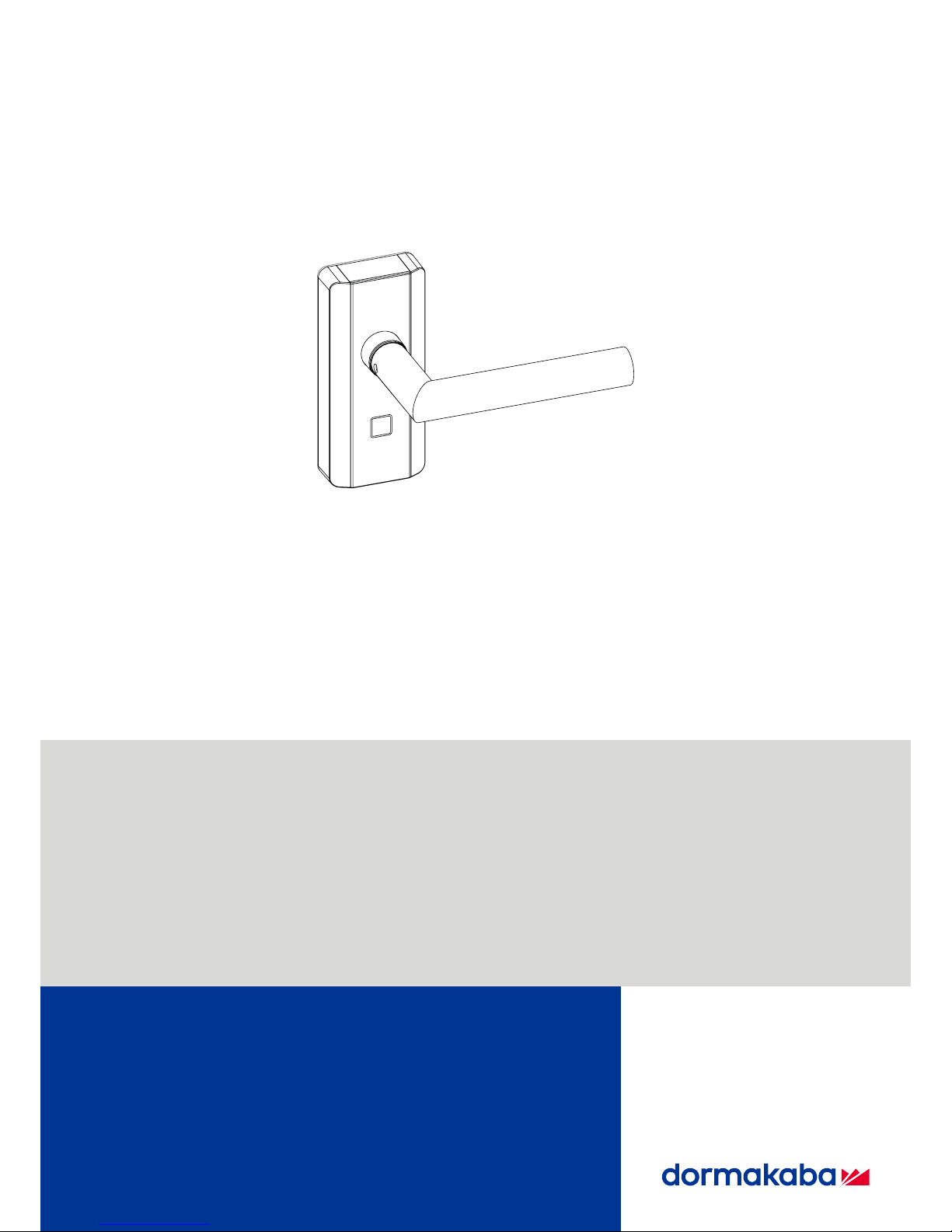
dormakaba c-lever compact
HBC
08/2017
EN
Technical Manual
Page 2

dormakaba Schweiz AG
Hofwisenstrasse 24
8153 Rümlang
Switzerland
T: +41 (0)44 818 93 11
www.dormakaba.com
dormakaba Schweiz AG
Mühlebühlstrasse 23
8620 Wetzikon
Switzerland
T: +41 (0)44 931 61 11
www.dormakaba.com
dormakaba EAD GmbH
Albertistrasse 3
78056 Villingen-Schwenningen
Germany
T: +49 7720 60 30
www.dormakaba.com
Registered in: Heiligenhaus
Copyright © dormakaba 2017
All rights reserved.
No part of this document may be reproduced or used in any form or by any means without prior written permission of dormakaba Schweiz AG.
All names and logos of third-party products and services are the property of their respective owners.
Subject to technical changes.
08/2017
Page 3

Technical Manual
308/2017 dormakaba c-lever compact
1 About this document 5
1.1 Target group 5
1.2 Validity 5
1.3 Contents and purpose 5
1.4 Supplementary documentation 5
1.5 Abbreviations/definition of terms 7
1.6 Hazard categories 8
1.7 Notes 8
1.8 Symbols 8
2 Basic safety instructions 9
2.1 Designated use 9
2.2 Product changes 9
2.3 ESD prevention measures 9
2.4 Handling of lithium batteries 10
2.5 Dealing with powerful magnets 10
3 Product description 11
3.1 Overview 11
3.2 Structure 11
3.3 Scope of delivery 12
3.4 Technical data 12
3.4.1 Dimensions 14
3.4.2 Conformity 14
4 Installation 15
4.1 Check minimum distance 15
4.2 Drilling fixing holes 15
4.3 Inserting the battery holder 16
4.4 Additional torsion lock 16
4.5 Securing the battery holder more tightly 17
4.6 Mounting the outside lever handle 17
4.7 Mounting the spindle 18
4.8 Inserting the c-lever into the lock 18
4.9 Mounting the inside rosette and lever handle 18
4.10 Removing the protective film 19
4.11 Switch off 'Bolt Recreation Time' 19
4.12 Dismantling 20
4.12.1 Dismantling the inside rosette and lever handle 20
4.12.2 Removing the inside lever handle from the rosette 20
4.12.3 Removing the c-lever from the lock 20
4.12.4 Removing the battery holder locking screw 20
4.12.5 Removing the outside lever handle 20
5 Programming 21
5.1 Initial programming of MRD components 21
5.2 Master media 21
5.3 User media 21
5.4 Program structures 22
5.5 A/B and B structures 22
5.6 Programming user media with B masters 23
5.7 Deleting individual user media 24
5.8 Deleting individual B masters 25
5.9 Deleting all user media 26
Page 4

Technical Manual
4 08/2017dormakaba c-lever compact
5.10 INI reset with master media for whitelist and CardLink™ 27
6 Operation 29
6.1 Opening with user media 29
7 Maintenance 30
7.1 Maintenance table 30
7.2 Cleaning 30
8 Service 31
8.1 Replacing the batteries 31
8.2 Connecting the programmer 32
8.3 Configuration and traceback 32
9 Troubleshooting 33
9.1 Error analysis 33
10 Disposal / dismantling 34
10.1 Decommissioning / dismantling 34
10.2 Disposal 34
11 Packaging/return 35
11.1 Complete devices 35
11.2 Electronic component assemblies 35
Page 5

About this documentTechnical Manual
508/2017 dormakaba c-lever compact
1 About this document
This section contains information for the proper use of this document.
1.1 Target group
This quick start guide is intended for skilled persons only.
The descriptions are intended for skilled persons trained by the manufacturer. The descrip-
tions are no replacement for product training.
For reasons of equipment safety, the installation, maintenance and service measures de-
scribed in this documentation should only be carried out by skilled persons in accordance with
EN 62368-1 (Audio/Video, Information and Communication Technology Equipment – Part 1:
Safety Requirements).
Skilled person is the designation for people who have the appropriate technical training and
experience in setting up the equipment. Skilled persons are expected to use their training and
experience to identify any risks to themselves and others that may arise while carrying out
these activities, and to minimise these risks as far as possible. It is the skilled person’s responsibility to ensure that the conditions stated by the manufacturer and the applicable regulations and standards are complied with when carrying out these actions.
This documentation is also used to provide information for persons with the following tasks:
• Project planning and project implementation
• Commissioning the product within the network
• Connecting the product to user software by programming customer applications
• Customer-specific adjustments with product parametrisation
1.2 Validity
This document describes the product:
Product designation: c-lever compact
Types: 2724-K6
2725-K6
Article numbers and variants:
2725-K6 c-lever compact, standard
2724-K6 c-lever compact, half
This document describes all product versions and all optional features and functions. Options
are subject to a charge and therefore only available if purchased.
1.3 Contents and purpose
The contents of these instructions are limited to the installation, operation, maintenance and
servicing of the product.
1.4 Supplementary documentation
The following documents are available from the sales partners:
• Operating manual programmer 1460
Page 6

About this document Technical Manual
6 08/2017dormakaba c-lever compact
• User manual for programming and signals of the Kaba evolo components
• System description Kaba evolo
• Planning guideline wireless
• Documentation for currently installed system software
Page 7
About this documentTechnical Manual
708/2017 dormakaba c-lever compact
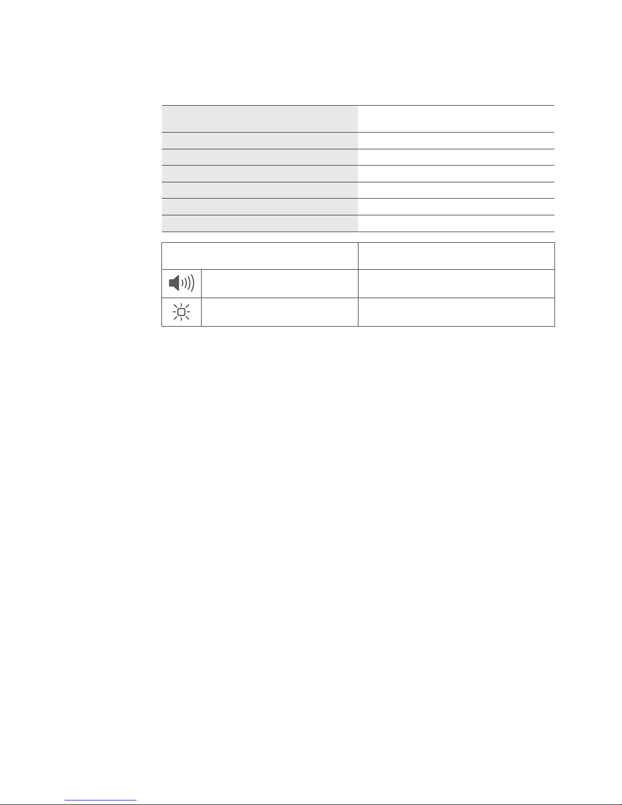
1.5 Abbreviations/definition of terms
To make this document easier to read, the following short designations are used for the
product designations, as well as the following symbols:
Short designation Product designation
c-lever c-lever compact
evolo component c-lever compact
Programmer Programmer 1460
S-module S-module for c-lever
KEM Kaba evolo Manager
MRD Multi RFID device
Symbols
Acoustic signal
Visual signal
Page 8
About this document Technical Manual
8 08/2017dormakaba c-lever compact
1.6 Hazard categories
Instructions with information on what to do and not to do to prevent injury and material
damage are denoted specially.
Please follow all hazard instructions. These are intended to help prevent accidents and prevent damage.
These instructions are divided into the following categories:
CAUTION
Low risk
Denotes a potentially dangerous situation that could lead to minor injury.
NOTICE
Important information on the correct use of the product.
Failure to comply with these instructions could lead to malfunctions. The product and/or objects in the local vicinity could be damaged.
1.7 Notes
Information is denoted by this symbol.
Tips on using the product are useful pieces of information.
They help to make best use of the product and its functions.
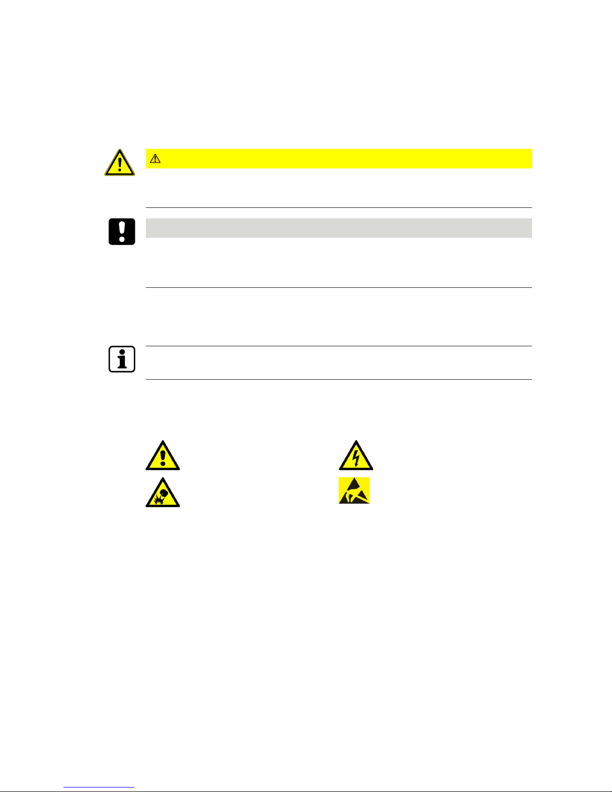
1.8 Symbols
Symbols with the following meanings are used for hazards (depending on hazard source.)
General hazard Hazard from electric shock
Risk of explosion Risk to electronic components from
electrostatic discharge
Page 9
Basic safety instructionsTechnical Manual
908/2017 dormakaba c-lever compact
2 Basic safety instructions
This product has been built to state-of-the-art standards and in line with established safety
regulations. However, hazards for persons and property may arise when handling the product.
Read and observe the following safety instructions before using the product.
2.1 Designated use
This product is intended for use as specified and explained in the Product description section
only. Any other use is considered non-designated use. The manufacturer is not liable for any
damage or injury due to non-designated use. The user/facility operator is the sole person to
bear risks for non-designated use.
2.2 Product changes
NOTICE
No changes should be made to the product, unless in accordance with changes described in
the instructions.
2.3 ESD prevention measures
NOTICE
Risk for electronic components due to electrostatic discharge.
Incorrect handling of electronic PCBs or components can result in damage which will cause a
complete breakdown or sporadic errors.
• General ESD prevention measures must be observed when installing or repairing the
product.
• Wear an anti-static wrist strap when handling electronic components. Connect the end of
the strap to a discharge box or a non-painted, earthed metal component. This way, static
discharges are channelled away from your body safely and effectively.
• Handle a PCB along its edges only. Do not touch the PCB or connectors.
• Place dismantled components on an anti-static surface or in an anti-static shielded container.
• Avoid contact between PCBs and clothing. The wrist strap protects PCBs against an electrostatic discharge voltage from the body only. However, damage can also be caused by
an electrostatic discharge voltage from clothing.
• Transport and ship dismantled modules in conductive anti-static bags only.
Page 10
Basic safety instructions Technical Manual
10 08/2017dormakaba c-lever compact
2.4 Handling of lithium batteries
NOTICE
Lithium batteries can explode or burst explosively.
Improper handling of lithium batteries can lead to fires and explosions.
• Only replace lithium batteries with batteries of the same type.
• Do not open, drill through or squash lithium batteries.
• Do not burn lithium batteries or expose them to high temperatures.
• Do not short circuit lithium batteries.
• Do not recharge lithium batteries.
2.5 Dealing with powerful magnets
WARNING
Magnets can affect the functionality of pacemakers and implanted defibrillators.
The functions of pacemakers or implanted defibrillators may be impaired.
Pacemakers may be inadvertently switched to test mode, causing those who wear them to
feel unwell.
• People wearing such devices should maintain an appropriate distance from magnets.
• People wearing such devices should be warned before approaching magnets.
Page 11

Product descriptionTechnical Manual
1108/2017 dormakaba c-lever compact
3 Product description
This section provides an overview of the product and gives information on technical details.
3.1 Overview
The c-lever compact is an electronic door fitting complete with an antenna (reading antenna)
and mechatronics unit in the outside shield. After identification using authorised media, the
lock and door can be opened manually. An acoustic and optical signal denotes access authorisation.
c-lever compact with wireless module and activated wireless function:
the device communicates via wireless gateway with the host system.
The system software determines the supported functions.
See also the wireless planning guideline and instructions for the system software
3.2 Structure
1 2 3 161513 144 6 75 8 9 11 1210
Item Item
1 Inside handle (optional) 9 M2.5x6 battery holder locking
screw
Not included in scope of delivery
2 M6x6 threaded pin (ISO 4029 /
DIN 916)
10 Mechatronics unit with backplate
3 Inside rosette cover (optional) 11 Battery holder
4 Fixing screws for inside rosette
(2 pieces)
12 Opening tool (optional)
5 Inside rosette ‘round’ (optional) 13 Batteries, AAA lithium
(2 pieces)
6 Spindle (square pin) 14 Guide ring
7 Flexible support plate (increases
torque resistance)
15 M6x8 threaded pin (ISO 4029 /
DIN 916)
8 Sleeves 16 Outside handle
Page 12

Product description Technical Manual
12 08/2017dormakaba c-lever compact
3.3 Scope of delivery
• 1 c-lever compact • 2 batteries, AAA lithium
• 1 outside lever handle • Fastening materials
• 1 spindle • 1 drilling template
• 1 handle rosette (optional) • 1 set of instructions
• 1 inside lever handle (optional) • Sleeves
[}4.4]
Overview of backplates
1 2 3 4
Item Backplate designation
1 Sweden (SV) *
2 Finland (FI)
3 Japan (JP)
4 Australia (AU)
*Version described in this document.
3.4 Technical data
Technical data
Connection
Data transfer RFID
Hardware
Lever handle Assorted variants (see
product catalogue)
Fitting Zinc housing HxWxD 122x54x23
Antenna cover Synthetic material
Power supply
Batteries 1.5V, AAA lithium
Ambient conditions
1
Protection type IP54 Outside
Temperature -25°C – +70°C The temperature range de-
pends on the battery manufacturer’s specifications.
Page 13

Product descriptionTechnical Manual
1308/2017 dormakaba c-lever compact
Technical data
Humidity 0%–95% rel. hum., non-con-
densing
Climate Not suitable for heavily cor-
rosive atmospheres (chlorine,
ammonia).
Rooms Not to be used in potentially
explosive environments.
Identification technology
MRD Multi RFID device
LEGIC advant prime
MIFARE DESFire classic
Standards
1
Fire protection DIN 18273 tested in accord-
ance with EN 1634-1
min. EI230-C (EI290-C)
DO 20.31
EN179 According to test certificate
Protection class EN 1906 class 0
Usage class EN 1906 class 3
Cycles
Battery life at 20 °C > 60,000 cycles
1
Depending on configuration
Battery life at -20 °C TBD
1
Certification not yet complete
Page 14

Product description Technical Manual
14 08/2017dormakaba c-lever compact
3.4.1 Dimensions
125
52
122,8
54,7
79,4 43,4
23,0
34
5
±50°
3.4.2 Conformity
This product conforms to the EU directives
2014/53/EU Radio Equipment Directive
2014/35/EU LVD Directive
2011/65/EU RoHS Directive
You can download the original declaration of conformity in PDF format at www.kaba.com/con-
formity.
Page 15

InstallationTechnical Manual
1508/2017 dormakaba c-lever compact
4 Installation
This chapter describes the installation of the product.
4.1 Check minimum distance
• Ensure that there is a space of at least 50mm to pull out the battery holder.
>50
4.2 Drilling fixing holes
Replace locks that do not comply with DIN standard 18251-1 (EN 12209: 2015).
The fitting used determines the position, number and diameter of the drill holes.
ø >20 mm
ü Existing fitting removed
1. If there are no existing drill holes:
Mark the drill holes on the outside and inside of the door.
2. Remove the lock.
3. Note: Do not drill through the door.
Drill the holes up to the lock mortise.
4. Clean the lock mortise.
5. Insert the lock.
Page 16

Installation Technical Manual
16 08/2017dormakaba c-lever compact
4.3 Inserting the battery holder
• Insert the battery holder, complete with batteries, into the mechatronics unit.
– The battery holder clicks into place.
– The green light briefly illuminates once.
1x
4.4 Additional torsion lock
• Measure the drill hole diameter on the door.
• Select suitable sleeves to bridge the gap.
• Attach the sleeves.
( )
( )
( )
( )
Page 17

InstallationTechnical Manual
1708/2017 dormakaba c-lever compact
4.5 Securing the battery holder more tightly
The battery holder can be secured more tightly using a screw.
The screw (M2.5x6) is not included in the scope of delivery.
Use of the battery holder locking screw increases the amount of effort involved in replacing
the batteries, see Dismantling [}4.12].
1.
2. 3.
1. Remove the flexible support plate.
2. Secure the battery holder with the battery holder locking screw (M2.5x6).
3. Attach the flexible support plate.
4.6 Mounting the outside lever handle
1. Position the guide ring on the mechatronics unit.
2. Attach the lever handle in the desired position on the square.
3. Screw the M6x8 threaded pin (with threadlocker) into the lever handle and secure in
place.
Page 18

Installation Technical Manual
18 08/2017dormakaba c-lever compact
4.7 Mounting the spindle
1. Centre the lug (highlighted in blue) if it is not already central.
8 x 8
8,5 x 8,5
(mm)
2. Align the spindle correctly.
3. Insert the spindle into the mechatronics unit as shown.
ð The spindle clicks into place.
4.8 Inserting the c-lever into the lock
With the spindle on the outside of the door, push the c-lever through the lock hub.
4.9 Mounting the inside rosette and lever handle
The lever handle can only be removed with a special tool after attaching it to the rosette.
1.
2. 3. 5.
4.
1. Attach the (optional) rosette with the plastic attachment (highlighted in blue) pointing
down. Align the c-lever on the door.
2. Screw the rosette securely in place.
Page 19

InstallationTechnical Manual
1908/2017 dormakaba c-lever compact
3. Align the cover and place it on the rosette.
4. Attach the lever handle in the desired position on the spindle.
ð The lever handle locks audibly into place.
5. Screw the lever handle securely in place using the M6x6 pin screw.
4.10 Removing the protective film
• Remove the protective film.
4.11 Switch off 'Bolt Recreation Time'
• Switch off 'Bolt Recreation Time' in the system software and transfer to the device using
the programmer.
Refer to the documentation for currently installed system software.
'Bolt Recreation Time' defines the time interval at which the engaging state of the mechatronics unit should be checked.
Page 20

Installation Technical Manual
20 08/2017dormakaba c-lever compact
4.12 Dismantling
4.12.1 Dismantling the inside rosette and lever handle
2.
1.
3.
1. Remove the cover from the inside rosette.
2. Loosen the screws.
3. Remove both the lever handle and the rosette.
The lever handle can only be removed with a special tool after attaching it to the rosette.
4.12.2 Removing the inside lever handle from the rosette
• Use spreader forceps to push the circlip apart and simultaneously remove the handle.
4.12.3 Removing the c-lever from the lock
• Pull the c-lever out of the lock hub.
4.12.4 Removing the battery holder locking screw
1.
2.
If present: Remove the battery holder locking screw.
1. Remove the flexible support plate.
2. Unscrew the battery holder locking screw.
4.12.5 Removing the outside lever handle
• Unscrew the threaded pin from the lever handle and remove the lever handle.
Page 21

ProgrammingTechnical Manual
2108/2017 dormakaba c-lever compact
5 Programming
This section describes how to program the components.
5.1 Initial programming of MRD components
When first used, multi-RFID (MRD) components are set to the technology in which the components are used with a master LEGIC or MIFARE. The components then behave as defined
for the authorisation types LEGIC (LEA) or MIFARE (MID).
Note: After an INI reset using master media, the components must then be re-programmed
using a master LEGIC or MIFARE.
5.2 Master media
With the A and B master Media the components are programmed directly. The B masters are
organised under an A master. The master media do not have any access authorisations.
5.3 User media
All User media are organised under a B master.
NOTICE
Lost User media should be immediately blocked and deleted from all components.
(Delete lost User media in the KEM system software in the whitelist (add CardLink to the
blacklist) or delete all User media with the corresponding master and then re-program all User
media).
Page 22

Programming Technical Manual
22 08/2017dormakaba c-lever compact
5.4 Program structures
All components can be organised manually in an A/B structure or in a B structure.
In the A/B structure, up to 200 B masters can be created with one A master. The User media
cannot be directly programmed in an A structure.
Separate access authorisations to User media can be issued with each B master. User media
can be programmed with different B masters but not with the same components.
Each component can be programmed with up to 4000 User media. These can be distributed
across the various B masters as required. For example, a B1 master only manages 50 users
whilst another master, B2, manages up to 3950 users.
5.5 A/B and B structures
A/B- structure
B- structure
Master A
Master B
User media
Page 23

ProgrammingTechnical Manual
2308/2017 dormakaba c-lever compact
5.6 Programming user media with B masters
Components confirm the detection of media with acoustic and visual signals.
In this case, the light ring glows green for as long as the medium is located within the antenna
field and is read.
Programming the
User media
Action
1
1 s
Beep
Launch programming mode:
Master B approx. 1 s hold in front
of the antenna.
1 x short
2
1 s
Beep
Program User media:
User media approx. 1 s hold in front
of the antenna.
1 x short
3
1 s
Beep
Additional User media approx. 1 s
hold in front of the antenna.
1 x short
4
Beeeep
1 s
To complete:
Master B approx. 1 shold in front of
the antenna.
Note: If no master medium is held
up within 20 seconds, programming mode ends automatically and
one long acoustic signal sounds.
1 x long
Page 24

Programming Technical Manual
24 08/2017dormakaba c-lever compact
5.7 Deleting individual user media
In this case, the light ring glows green for as long as the medium is located within the antenna
field and is read.
Deleting
User media
Action
1
1 s
Beep
Launch programming mode:
Master B approx. 1 s hold in front
of the antenna.
1 x short
3 s
2
Beep
Beep
Delete User media:
User media approx. 3 s hold in front
of the antenna.
2 x short
3
Beeeep
1 s
To complete:
Master B approx. 1 shold in front of
the antenna.
Note: If no master medium is held
up within 20 seconds, programming mode ends automatically and
one long acoustic signal sounds.
1 x long
Page 25

ProgrammingTechnical Manual
2508/2017 dormakaba c-lever compact
5.8 Deleting individual B masters
NOTICE
All User media under Master B and the Master B medium under Master A are deleted.
In this case, the light ring glows green for as long as the medium is located within the antenna
field and is read.
Deleting Master Bs Action
1
1 s
Beep
Launch programming mode:
hold in front of the antenna. Mas-
ter A approx. 1 s
1 x short
3 s
2
Beep
Beep
Delete Master B and all user media:
Master B approx. hold in front of
the antenna. 3s
2 x short
3
Beeeep
1 s
To complete:
Master A approx. 1 s hold in front
of the antenna.
Note: If no master medium is held
up within 20 seconds, programming mode ends automatically and
one long acoustic signal sounds.
1 x long
Page 26

Programming Technical Manual
26 08/2017dormakaba c-lever compact
5.9 Deleting all user media
Components should not be in programming mode.
In this case, the light ring glows green for as long as the medium is located within the antenna
field and is read.
Deleting
user media
Action
10 s
1
Beep
Beep
hold in front of the antenna. Master B approx. 10 s
All User media under the Master B
are deleted.
2 x short
1 x long
1
1 x short
Key:
1
Firmware version 42xx
Page 27

ProgrammingTechnical Manual
2708/2017 dormakaba c-lever compact
5.10 INI reset with master media for whitelist and CardLink™
An INI reset can be used to restore the factory settings for the components.
NOTICE
All User media and master media as well as the traceback are deleted.
Components should not be in programming mode.
INI reset for whitelist
In this case, the light ring glows green for as long as the medium is located within the antenna
field and is read.
INI reset with master Action
15 s
1
Beep
Beep
Master B structure
Master B approx. 15 s hold in front
of the antenna. The INI reset will be
executed after 15 s.
After 10 s,
1 x long,
1 x short,
after 15 s,
2 x short
15 s
1
Beep
Beep
Master A/B structure
Master A approx. 15 s hold in front
of the antenna. The INI reset will be
executed after 15 s.
After 10 s,
1 x long,
1 x short,
after 15 s,
2 x short
INI reset for CardLink
In this case, the light ring glows green for as long as the medium is located within the antenna
field and is read.
INI reset with master Action
15 s
1
Beep
Beep
B master
Master B approx. 15 s hold in front
of the antenna. The INI reset will be
executed after 15 s.
2 x short
Page 28

Programming Technical Manual
28 08/2017dormakaba c-lever compact
INI reset with master Action
15 s
1
Beep
Beep
Master A
Master A approx. 15 s hold in front
of the antenna. The INI reset will be
executed after 15 s.
2 x short
Page 29

OperationTechnical Manual
2908/2017 dormakaba c-lever compact
6 Operation
This section describes operation of the product.
6.1 Opening with user media
Before being used for the first time, access authorisations for the relevant system software
must be transmitted to the User media.
2
1
2
Beep
1. Hold authorised user medium in front of the antenna of the
fitting.
-> The acoustic and visual signals1 confirm access authorisation.
Note: The c-lever's opening time is limited; after this time has
elapsed, the c-lever closes automatically. Upon delivery, the opening
time is approx. 6 s, but this can be adjusted using the 1460 programmer or the system software.
2. Activate the lock by pushing the lever handle.
3. The door can be opened.
Beep
Beep
Beep
Beep
If there is an attempt to gain access using unauthorised user media,
the acoustic1 signal will sound four times and the red1 light will
briefly flash four times.
Key:
1
If the function(s) have been activated using the programmer 1460 or the system software.
Page 30

Maintenance Technical Manual
30 08/2017dormakaba c-lever compact
7 Maintenance
This section describes product maintenance.
7.1 Maintenance table
The component's mechanism and/or electronics do not require any maintenance.
NOTICE
Opening the mechatronic unit.
Opening the mechatronic unit releases the manufacturer from any liability under the guarantee.
Part/function Measures Interval
Batteries Function check in accordance with instruc-
tions
12 months
Replacing the batteries ≤ 24 months
1
Clock (components) Check and set clock time with the system
software
12 months
Firmware update To modify functionality
See the system description
as required
Table1:
Maintenance interval – evolo components
Key:
1
Device with lithium batteries
7.2 Cleaning
Only disinfection agents that are explicitly formulated for cleaning delicate metal surfaces
and plastics may be used. The use of unsuitable cleaning agents or methods can damage the
components' surface.
1. Use a soft, damp cloth to clean the surface.
Page 31

ServiceTechnical Manual
3108/2017 dormakaba c-lever compact
8 Service
8.1 Replacing the batteries
WARNING
Hazard due to strong magnetic field
The functions of pacemakers or implanted defibrillators may be impaired.
• People wearing such devices should maintain a distance of at least 50cm from the opening tool.
Whilst the battery is being changed, all the data (access authorisations, configurations and
traceback) is retained in the battery-independent memory. The clock settings are lost after 45
seconds.
1.
2. 3. 4.
5. 6. 7.
1x
Also see about this
2 4.12.4 Removing the battery holder locking screw [}20]
2 4.5 Securing the battery holder more tightly [}17]
2 6 Operation [}29]
Page 32

Service Technical Manual
32 08/2017dormakaba c-lever compact
8.2 Connecting the programmer
• Connect the c-lever and programmer using the programming cable.
8.3 Configuration and traceback
For correct time management, the clock time and the date on the device must be up-to-date.
c-lever compact with wireless module and activated wireless option:
Configuration, updates (e.g. the clock time) and traceback read-outs are performed by the
system software via wireless gateway.
c-lever compact with wireless module and deactivated wireless function:
Configuration, updates (e.g. the clock time) and traceback read-outs are performed using the
programmer.
The traceback is transmitted from the programmer to the system software for evaluation.
See also [}1.4] > Programmer
c-lever compact without wireless module:
Configuration, updates (e.g. of the clock time) and traceback read-outs are performed using
the programmer.
The traceback is transmitted from the programmer to the system software for evaluation.
See also [}1.4] > Programmer
Also see about this
2 1.4 Supplementary documentation [}5]
Page 33

TroubleshootingTechnical Manual
3308/2017 dormakaba c-lever compact
9 Troubleshooting
This section provides important information on rectifying product errors.
9.1 Error analysis
Symptoms Possible causes Measures
The use of a master or user
medium is confirmed via various acoustic and/or visual
signals by the components
1 x very
short
9 x
flashes
red
– Battery “Low”
(V4 from FW 42.XX)
– Replace the batteries
Door does not open: authorisation via an authorised user
medium is confirmed by
acoustic signals
1 x very
long
— – Alarm — Battery “Empty” – Replace the batteries
Door does not open: authorisation by an authorised user
medium is confirmed via
acoustic and visual signals
4 x
short
4 x
short
red
– Medium not programmed
– Outside the time window
– Program medium
– Check time profiles
Door does not open: authorisation by an authorised user
medium is confirmed via
acoustic and visual signals
1 x long
1 x
short
1 x long
1 x
short
green
– Internal clock in component
has failed
– Check programming and
clock time
User medium cannot be programmed
— — – 4000 media or groups
already programmed in the
e-module
– Defective medium
– Not the correct technology
– Contact customer service
Master medium cannot be
programmed
1 x
short
1 x red – E-module already pro-
grammed
– Execute INI reset for emodule
Master medium is not detected
— — – No power supply – Provide power supply
Other errors 3 x
short
1 x
short
red
1 x
short
green
1 x
short
red
– Unintentional restart —
Door is always open: the
lever handle on the outside is
always engaged
— — – TimePro function activated – Deactivate TimePro func-
tion
Door is always open: Door
does not open or close at
programmed time
— — – Time is missing on e-mod-
ule or is not correctly set
– Incorrect programming
– Set time, check programming
Page 34

Disposal / dismantling Technical Manual
34 08/2017dormakaba c-lever compact
10 Disposal / dismantling
10.1 Decommissioning / dismantling
• Remove or delete the device in the system software.
• Dismantle the device, see Dismantling
• Carry out a reset.
• Remove the battery/batteries.
10.2 Disposal
This product compliance with the WEEE Directive and is labelled with the "crossed-out
wheelie bin" WEEE symbol as German Industrial Standards (DIN) EN 50419.
The symbol indicates that electrical and electronic devices must be returned separately in EU
member states.
You must not dispose of the device in the household waste as per the European WEEE Directive.
The device's integral components must be separated before they are taken for recycling or
disposal. Old and used devices contain valuable recyclable materials which must be recycled.
Toxic and hazardous components may cause long-term damage to the environment if you dispose of them incorrectly.
Legislation (such as the Electrical and Electronic Equipment Act [ElektroG] in Germany) dictates that facility operators are obliged to return electrical and electronic devices to their
manufacturer, point of purchase or designated public collection points at the end of their life
cycle.
Disposal in Germany:
dormakaba EAD GmbH will take responsibility for correct disposal of supplied goods once
they are no longer in use as per statutory regulations (ElektroG in Germany). The owner of
the used electrical appliance bears any costs incurred for transport to the manufacturer's
plant.
Disposal in Switzerland:
the device is to be returned to an electrical appliance return point as per Regulation on Returning, Taking Back and Disposing of Electrical and Electronic Equipment (VREG).
In the EU, electrical appliances should be taken for disposal in accordance with the country's
respective disposal and environmental guidelines.
The owner/operator is responsible for deleting their personal data.
Dispose of packaging in an environmentally responsible fashion.
The packaging materials are recyclable. Do not dispose of packaging in the household waste;
take it to a recycling point instead.
Page 35

Packaging/returnTechnical Manual
3508/2017 dormakaba c-lever compact
11 Packaging/return
Improperly packed assembly groups and devices may produce extra costs due to damage during transport.
Please observe the following instructions when sending dormakaba products.
dormakaba is not liable for damage to products which is due to inadequate packaging.
11.1 Complete devices
The original packaging is specially made for the device. It provides optimum protection
against transport damage.
Always use the original packaging to return the device!
If this is not possible, you must provide packaging which will prevent any damage to the
device.
• Use a sturdy, thick-walled transport case or a box. The transport case should be large
enough to allow 8–10cm clearance between the unit and container wall.
• Wrap device in a suitable foil or place in a bag.
• Pad heavily around the device with foam padding or air bags, for example. The device
must not be able to move around within the packaging.
• Use dust-free, environmentally friendly fill material.
11.2 Electronic component assemblies
ESD-sensitive electronic component assemblies such as PCBs and readers should be stored,
transported and shipped in suitable anti-static packaging. Electronic component assemblies
must be packed at ESD-protected workstations. This should be carried out by persons who
are familiar with and comply with general ESD protection regulations.
Electronic component assemblies must be returned in packaging with sufficient ESD protection to
• make warranty claims in the event of malfunctions of any type.
• Delivery of replacements for electronic PCBs and components in replacement procedure.
Electronic components shipped in packaging without adequate ESD protection will not be
analysed or repaired to maintain a high quality standard; they will be taken directly to disposal instead.
 Loading...