

Page 1
DORMA
Installation Manual
Terminal M6D
Page 2

Page 3

M6D
Table of Contents
3
Table of Contents
1. General .................................4
1.1 Preface.................................5
1.2 Intended use.............................5
1.3 Safety instructions and warnings ..............5
1.4 Further Source of Information . . . . . . . . . . . . . . . .6
1.5 Disposal ...............................6
1.6 Functional principle . . . . . . . . . . . . . . . . . . . . . . .6
1.7 Components supplied ......................7
1.8 Assembly accessories (optional) ...............7
2. Assembly ................................8
2.1 Terminal design ..........................8
2.2 Casing variants ...........................8
2.3 Dimensions..............................9
2.4 Opening and closing the terminal .............10
2.5 Assembly preparations .....................11
2.6 Assembly with flush cabling .................12
2.7 Inclined console .........................13
2.8 Inclined console with 230 V supply voltage ......14
3. Connection variants ........................15
3.1 External connections of the M6D .............15
3.2 Power supply ...........................15
3.3 Communication interfaces ..................15
3.3.1 RS485 bus ...........................15
4. Commissioning ...........................16
4.1 Settings ...............................16
4.1.1 Bus address...........................16
4.1.2 Connection resistor ......................17
4.2 Tampering protection ......................17
4.3 Reader settings .........................18
5. Maintenance ............................19
5.1. Fuses ................................19
EU Declaration of conformity ...................20
6. Technical data ...........................24
Page 4

M6D
1. General
4
The information provided in these assembly instructions
may be modified without prior notification. All previous versions cease to be valid with the publication of these instructions.
The information in these assembly instructions has been
compiled to the best of our knowledge and in good faith.
DORMA accepts no liability for the correctness and completeness of the details provided.
In particular, DORMA cannot accept liability for any consequential damages due to incorrect or incomplete information.
The recommendations for installation provided in this manual are based on favourable basic conditions being present.
DORMA accepts no liability for the perfect functioning of
the M6D in external, non-system environments.
Despite every effort to prevent mistakes, they can never
be completely avoided. Therefore, we would be grateful to
receive notification of any errors or omissions.
DORMA accepts no liability for the information included in
this document being free of protected third party rights.
DORMA does not provide any licences to its own or to third
party patents or other protected rights with this document.
It is not permitted to print, reproduce or to pass this manual, or parts thereof, to third parties, other than for your own use,
without the approval of DORMA.
All rights reserved.
DORMA Time + Access GmbH
Postfach 21 01 85
53156 Bonn
http://www.dorma-time-access.de
E-Mail [email protected]
© Copyright 2011 by DORMA Time + Access GmbH
Diagram no.: 1053G-00-B1
Status: 10/13 V1.30
Page 5
M6D
1. General
5
1.1 Preface
This installation manual is intended to assist you in connecting and commissioning the M6D.
1.2 Intended use
The device is used as a time recording and access control
terminal.
Further details are described in chapter 1.6.
Any other use than that indicated is not permitted!
1.3 Safety instructions and warnings
This device has been constructed and tested in accordance
with the relevant current technological regulations. It left the
factory in perfect condition in terms of technological safety
and reliability. To maintain this condition and to ensure riskfree operation, the instructions and warnings given in this
assembly guide must be observed by the user.
• The device may only be used for the purpose intended by
the manufacturer.
• The installation and assembly of electrical devices may
only be carried out by an electrical engineer.
• Before opening the unit, always switch off the power
supply and verify that the device is free of voltage by performing a measurement.
• During assembly, please ensure that the requirements
laid down in the relevant device safety standard for the
unit are not negatively affected, as this would reduce the
safety level of the unit.
• Before switching on, ensure that the operating and control voltages connected do not exceed the permissible
values in accordance with the technical data.
• This unit conforms to EN 60950-1 protection class III
• The units must be operated with safety extra low voltage
(SELV)!
Electromagnetic compatibility:
• The device is designed for use in residential, business
and commercial areas and conforms to EN 61000-6-2
and 61000-6-3.
• The PCB is at risk from electrostatic discharge and the
relevant precautionary measures should be observed
(earthing, etc.).
Caution
• These devices may only be operated when fully assembled.
• The locking screws on unassigned connection terminals
should be screwed in as far as they will go.
• If it has to be assumed that danger-free operation is no
longer possible, take the unit out of operation and secure
against accidental use.
• If the failure or malfunctioning of the unit may result in
injury to persons or animals or in damage to works equipment, this must also be prevented by using additional
safety measures (limit switch, safety devices, etc.).
• Switch off the power supply before opening the device.
Page 6
M6D
1. General
6
1.4 Further Sources of Information
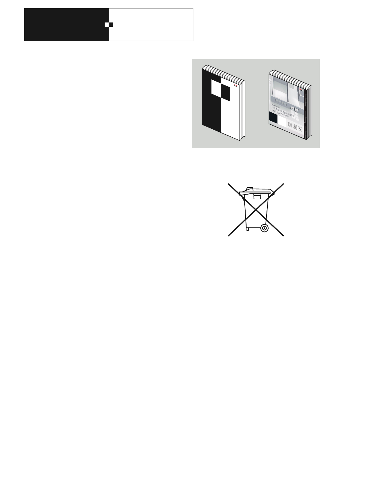
Further documents are available on request.
General Installation Guidelines
Specifications for planning attendance recording and
access control systems with our wired components.
Planner Manual
Examples of cross-system solutions
1.5 Disposal
The device was manufactured using recyclable materials and
components.
When disposing of the device and the packaging, please
ensure environmentally friendly recycling.
Information for EU Countries
European Directive 2002/96 EC applies to this device.
This means that this product must not be disposed of with
normal household waste. We, the manufacturer, will take
back our electric and electronic products and dispose of
them for you free of charge. Correct disposal of your old
equipment protects people and the environment from
possible harmful consequences.
1.6 Functional principle
The M6D terminal serves as a display and operation station
in an attendance recording system.
It has a keyboard that can be used to operate various queries and functions in the system.
The identity and the rights of the user are determined using
a badge and where applicable by entering a PIN. The badge
data is queried by the integrated reader.
The data recorded are sent via an RS485 bus to a host terminal for evaluation.
After they have been processed in the host, the result is
sent via the RS485 to the M6D terminal and shown visually
on a two-line display.
DORMA
Algeme ne
In tal tonsich linen
Z
Z
A
Page 7
M6D
1. General
7
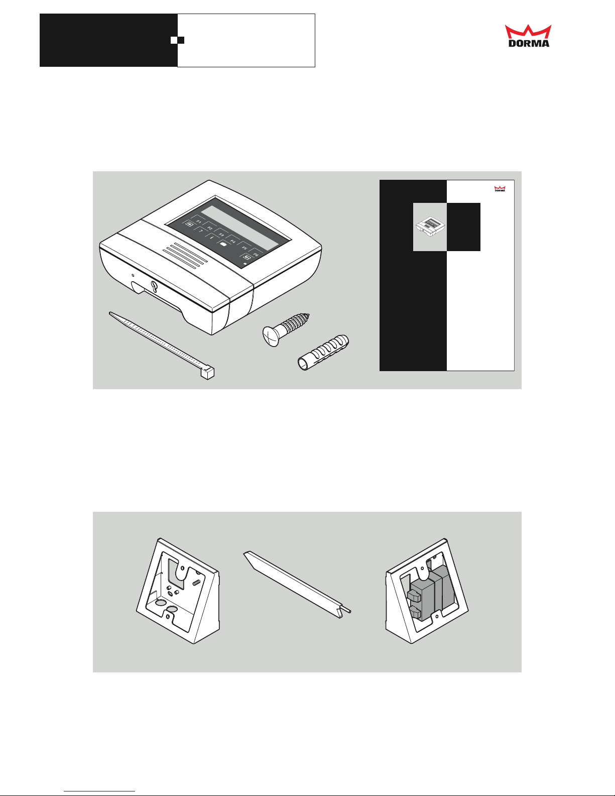
1.7 Components supplied
A M6D
B Assembly instructions
C 1 x cable binder
D 2 x Spax screws (4.5 x 35 mm)
E 2 x dowels (6 mm)
1 x drilling template
A
B
2x
E
D
2x
DORMA
Installation Manual
Terminal M6D
C
1x
1.8 Assembly accessories (optional)
a Inclined console, art. no. 1900070400119
b Inclined console with 230V-supply voltage, art. no. 1900070400120
c Front lock, art. no. 1900004912571
c
b
a
Page 8
M6D
2. Assembly
8
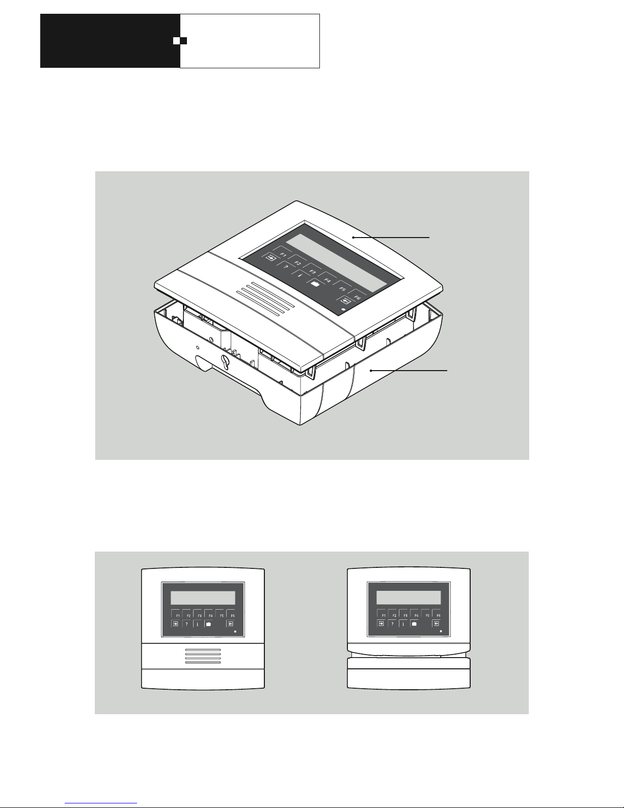
2.1 Terminal design
The terminal consists of the top casing section and the
bottom casing section.
The models are explained in the next chapter.
Top section
Bottom section
Contactless reader (PXL) Swipe reader (DZL)
2.2 Casing variants
Page 9
M6D
2. Assembly
9
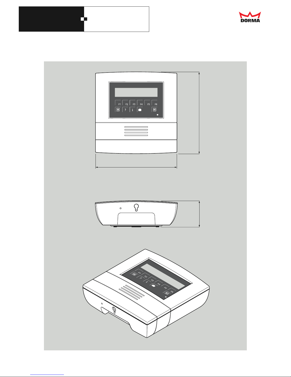
176,3 mm
59,3 mm
176,3 mm
2.3 Dimensions
Page 10
M6D
2. Assembly
10
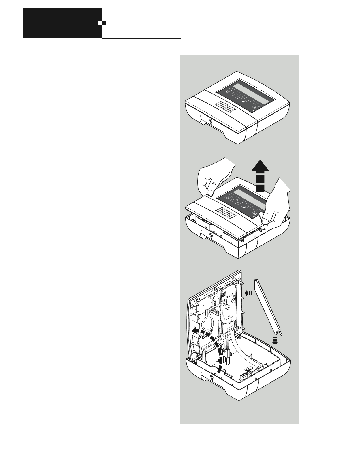
2.4 Opening and closing the
terminal
The unlocking mechanism is accessed through the hole on
the underside of the terminal. If there is a lock in this hole,
remove the lock first.
To open the casing you need a rod-shaped tool (such as a
screwdriver) which you insert through the unlocking hole.
Using strong pressure, increasing in force on the unlocking
piece on the inside, the casing will spring open. (See right.)
Then pull the top casing section vertically towards the wall
as far as it will go to remove it from the lower casing section. Then swivel the top casing section to the left.
To close the unit, follow the same steps in the reverse order.
When working on the open casing, it is advisable to lock
the front using the front locking catch. This tool can also be
used to open the terminal.
Please note the following points:
• Do not allow the flat-band cable between the top and
bottom casing sections to be trapped when closing.
• The unlocking piece must be positioned to fit the guide.
• The top casing section can only be positioned parallel to
the bottom section based on the design.
When the top casing section is positioned on the bottom
casing section, the unit can be closed using even pressure
on the right and left-hand sides of the top casing section.
This means that an audible "click" can be heard when the
unit is closed correctly.
d
Page 11
M6D
2. Assembly
11
2.5 Assembly preparations General
General
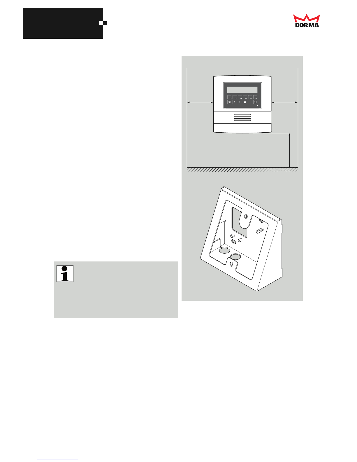
When planning the installation site for the terminal, the
required space specified in the diagram opposite must be
provided. This space is necessary to ensure problem-free
operation and sufficient room for servicing work.
The installation height specified is recommended to provide
persons of average height the optimum operation and view
of the display.
If it is necessary, or desired, that a different height is used,
an assembly wedge piece should be used.
Once the installation site has been determined, the cables
should be laid first of all. Specifications on the planning
and installation of time systems and access systems using
our components are described in the General Installation
Guidelines.
The following assembly types are possible:
• Flush cabling (standard)
• Inclined console assembly with flush cabling or surface
wiring
For each installation type, the relevant specifications on
the position of the cable infeed and cable length must be
observed.
M6D terminal with contactless readers
To prevent interference from both sides, the two
devices with contactless readers may not be
installed closer to each other than the minimum
specified distance.
This minimum distance depends on local specifications.
It should always be greater than 50 cm.
min.
165 mm
Top edge of finished floor
min.
165 mm
15000 mm
Inclined console
Page 12
M6D
2. Assembly
12
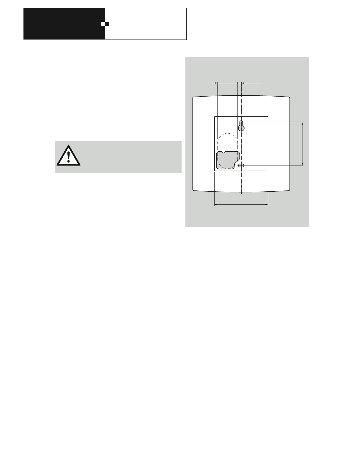
2.6 Assembly with flush cabling
For the cable outlet, use a flush box with a maximum width
of 40 mm. We recommend wall lighting connection boxes.
Refer to the illustration so that the cable emerges from the
wall correctly at the knock-out section on the back side of
the M6D. The box may not protrude above the contour of
the underside of the casing.
Then use the attached drilling template to draw the two
mounting holes required for fixing and drill them with a
6 mm drill bit.
Before drilling, ensure that you will not be
able to damage any cables or similar located
underneath the plaster. Now insert the dowels included with delivery into the drill holes.
Cable packaging
The data cable should be cut to a length of 120 mm so that
it can be easily connected after the terminal is installed.
Strip the cable completely from approx. 10 mm after the
wall opening.
Final assembly
Before the M6D is firmly attached, pull the connecting
cables through the opening in the rear panel. Finally, the
device can be screwed onto the wall with the screws included with delivery and aligned properly.
94mm
79mm
max. 40mmmin. 10mm
Underside of the casing
Casing contour
Page 13
M6D
2. Assembly
13
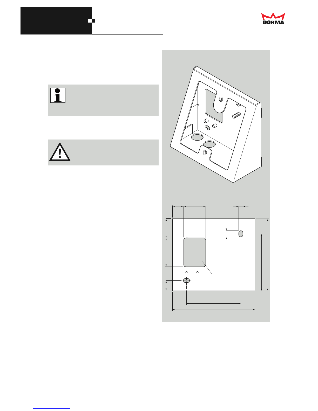
2.7 Inclined console
If the terminal needs to be installed underneath the recommended installation height of 1,500 mm, the poor viewing
angle should be adjusted using the inclined console.
There are two holes on the underside on the
right. These must be closed using the blind
plugs from the accessories kit. If the cables are
being laid directly against the wall, these need
to be punched out.
First the two mounting holes required for fixing are drawn in
accordance with the illustration below and drilled using a
6 mm drill bit.
Before drilling, ensure that you will not be
able to damage any cables or similar located
underneath the plaster.
Now insert the dowels included with delivery into the drill
holes, but do not mount the inclined console yet.
Cable packaging
The data cable should be cut to a length of 130 mm so that
it can be easily connected after the terminal is installed.
Strip the cable completely from approx. 60 mm after the
wall opening.
Final assembly
First pull the connecting cables through the opening in the
rear panel. Now the inclined console can be screwed onto
the wall. Afterward, insert the cables into the opening in the
rear panel of the terminal. Finally, the M6D can be screwed
onto the inclined console with the screws included with
delivery.
3116
6
284215
120
79
83
105
9
range of
cable exit
Page 14
M6D
2. Assembly
14
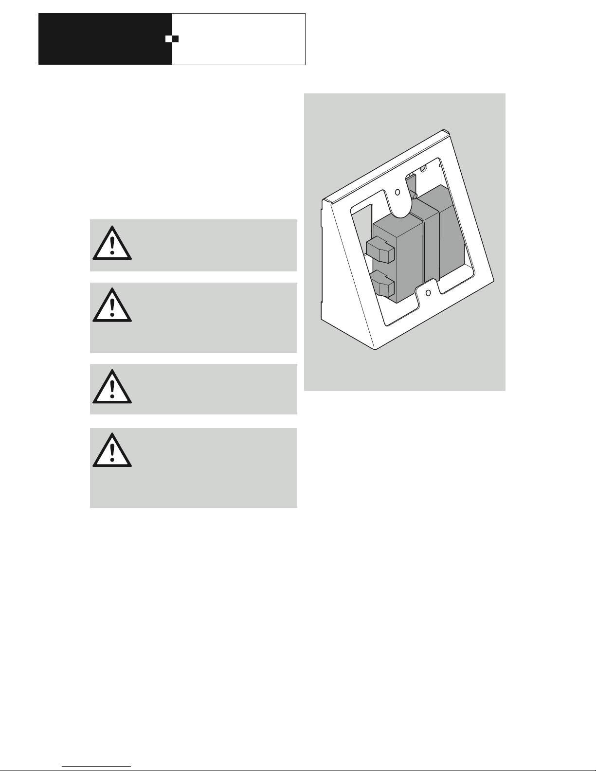
2.8 Inclined console with 230 V
supply voltage
To power the M6D with 230 V supply voltage, the inclined
console can be ordered with a built-in power supply unit.
To create the connection, connect the phase and the neutral
wire directly to the power supply unit. Connect the protective conductor to the earthing screw in the inclined console.
The power supply is designed for a permanent connection to the power supply circuit
only. It must be connected by a qualified
electrician only.
The power supply circuit for this power sup
ply requires a suitable, easily accessible
power isolating device with a minimum
contact gap of 3 mm and a fuse element to
protect against short circuits, both already
provided on site.
The earth conductor must be connected.
If the M6D-terminal is supplied with
alternating current (AC) it must not be used
for the power supply of sub-devices.
Sub-devices may only be supplied with
direct current (DC)!
Page 15
M6D
3. Connection variants
15
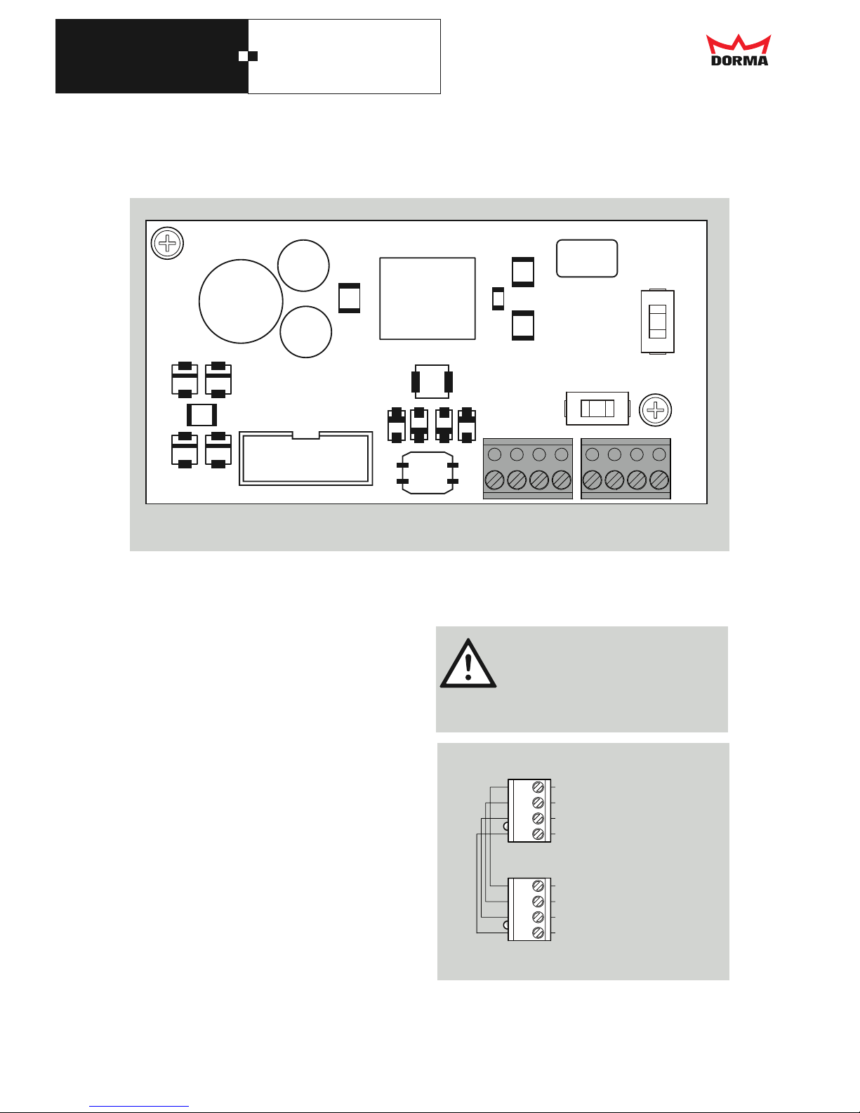
3.1 External connections of the M6D
All external connections are on the basic card.
ST103
24V
A(+) B(-) 0V
24V
A(+) B(-) 0V
ST102
3.2 Power supply
The power supply for the M6D is connected to terminal
24 V and 0 V of the ST102. ST103 serves as the connection for other bus devices.
The pin assignment of ST103 is identical with ST102.
The voltage must lie in the range of 16 V to 36 VDC or
24 VAC.
3.3 Communication interfaces
3.3.1 RS485 bus
The RS485 bus line is connected to the connection
terminals ST101 and ST102, signals A(+) and B(-).
The pin assignment of ST103 is identical with ST102.
3
1
B
A
1
A
B
3
ST102
ST103
0V
24V
B(-)
A(+)
0V
24V
B(-)
A(+)
RS485 bus
further bus
If the M6D-terminal is supplied with
alternating current (AC) it must not be used
for the power supply of sub-devices.
Sub-devices may only be supplied with
direct current (DC)!
Page 16
M6D
4. Commissioning
16
4.1 Settings
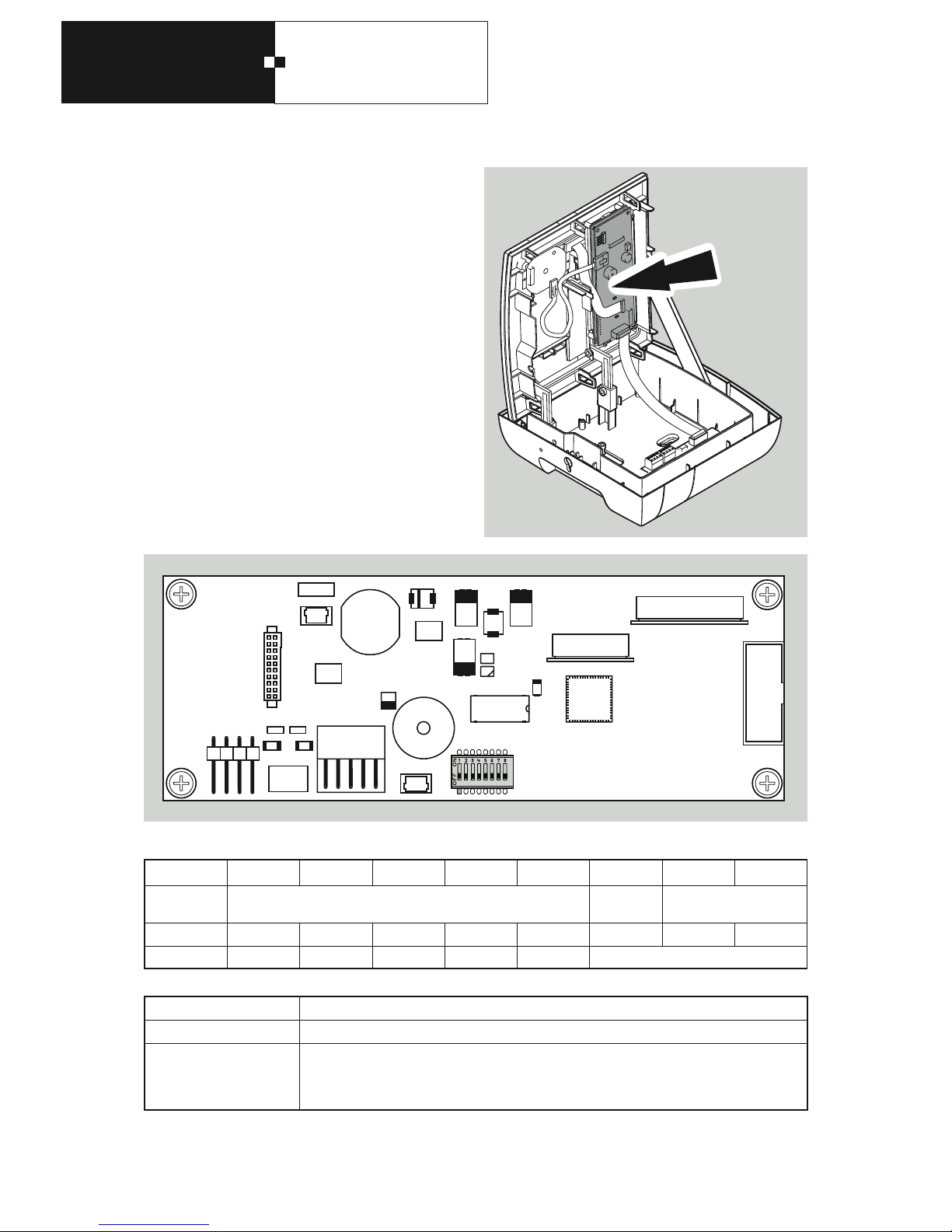
4.1.1 Bus address
The bus address can be set with the 8-pin DIP switch
SW201.
31 addresses are available.
The address 00 is reserved for the control unit.
SW201 1 2 3 4 5 6 7 8
Functionality
Bus address Test mode
RS485
Bus connection resistor
Bit0 Bit1 Bit2 Bit3 Bit4 on/off on/off on/off
Binary value 2
0
2
1
2
2
2
3
2
4
SW201 / 6 Funktion
off (factory setting) Normal mode: If switch SW201/6 = off, the M6D functions in normal mode.
on on test mode:
If switch SW201/6 = on, the test mode is activated if no communication occurs at the
RS485 interface after the M6D is switched on. If the M6D recognises communication at the
RS485 interface, it switches into normal mode.
SW201
Page 17
M6D
4. Commissioning
17
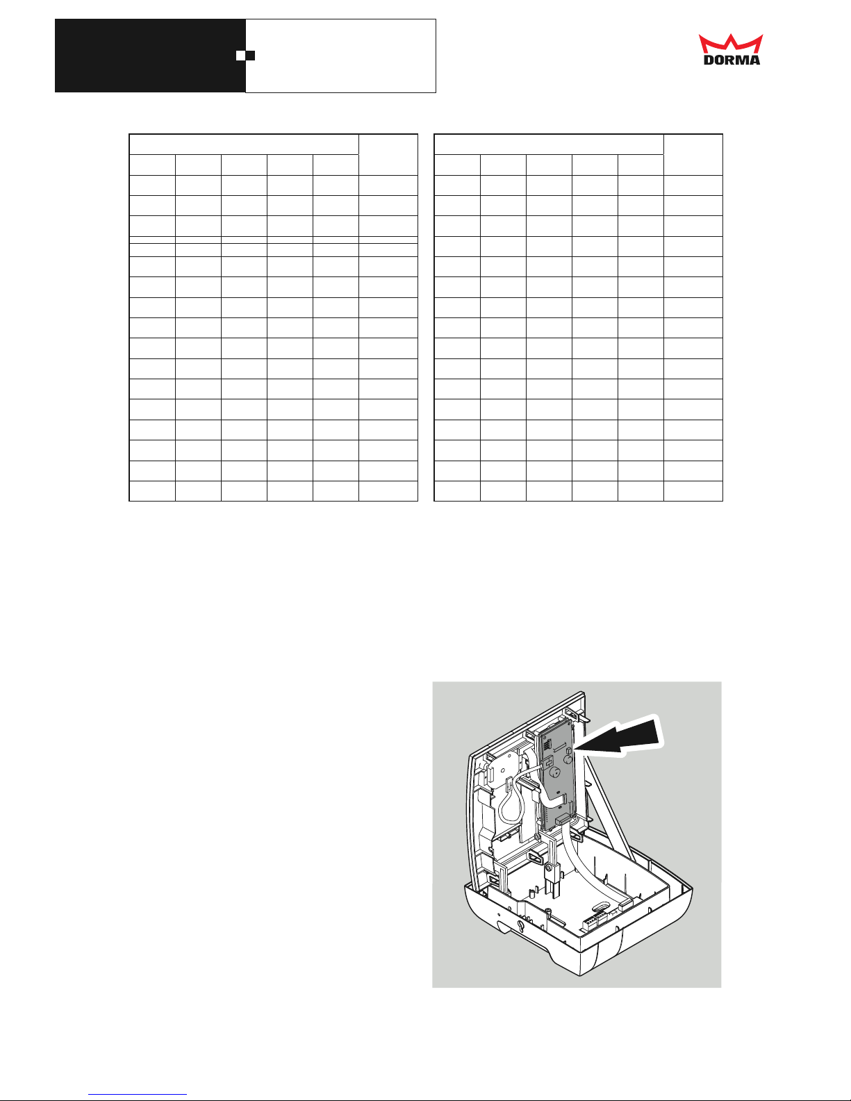
*) The address 00 is reserved for the control unit.
4.1.2 Connection resistor
The bus connection resistors must be switched on if the
M6D is the first or last bus device.
4.2 Tampering protection
A light barrier for tampering protection is integrated into the
M6D, which sends a signal to the higher level terminal if
the casing is opened.
Switch SW201
Address
(decimal)
1 2 3 4 5
off off off off off 00*
on off off off off 01
off on off off off 02
on on off off off 03
off off on off off 04
on off on off off 05
off on on off off 06
on on on off off 07
off off off on off 08
on off off on off 09
off on off on off 10
on on off on off 11
off off on on off 12
on off on on off 13
off on on on off 14
on on on on off 15
Switch SW201
Address
(decimal)
1 2 3 4 5
off off off off on 16
on off off off on 17
off on off off on 18
on on off off on 19
off off on off on 20
on off on off on 21
off on on off on 22
on on on off on 23
off off off on on 24
on off off on on 25
off on off on on 26
on on off on on 27
off off on on on 28
on off on on on 29
off on on on on 30
on on on on on 31
Page 18
M6D
4. Commissioning
18
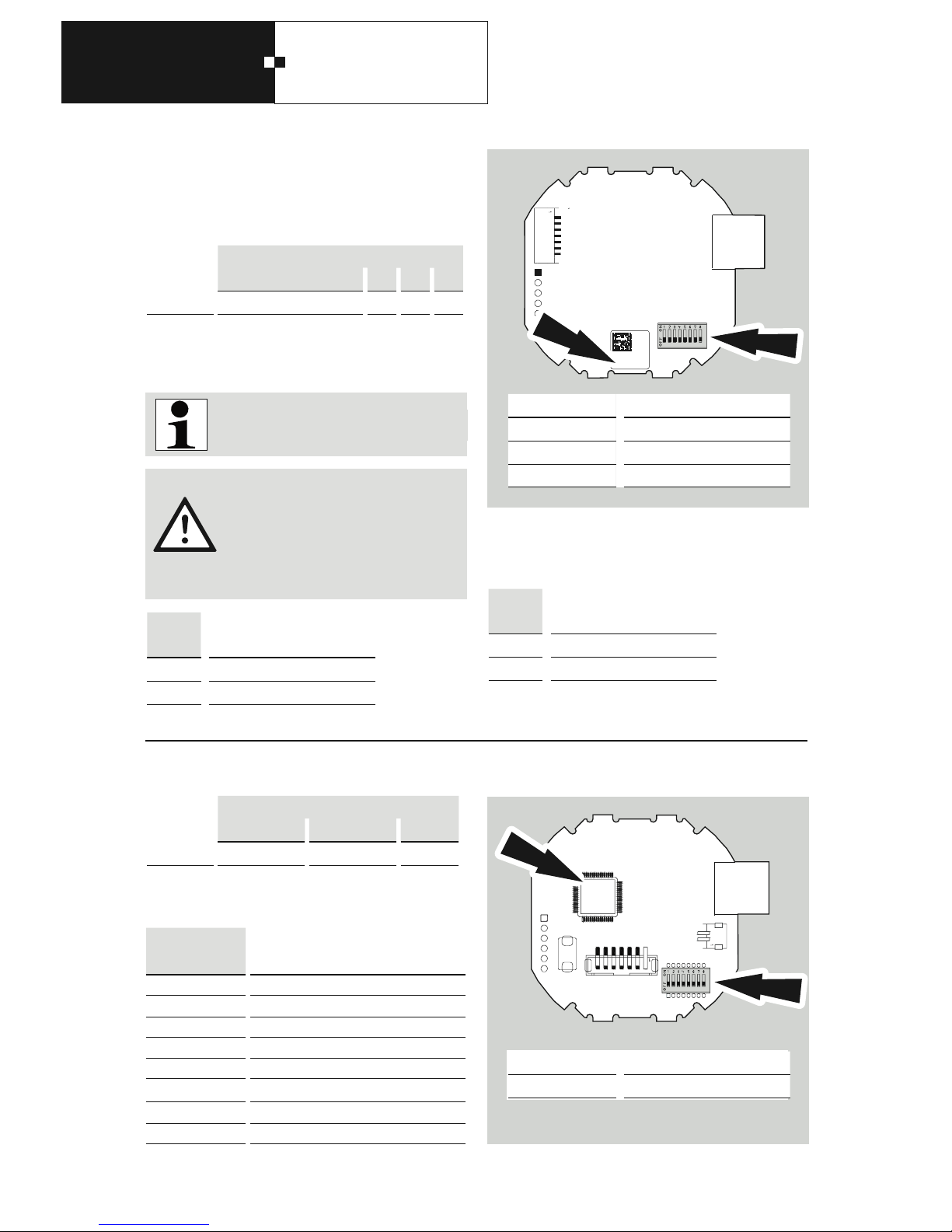
SW101
6
Configuration protection
off off
on active
4.2 Reader settings
Hitag (PX10)
Legic advant-Leser (PX51)
Mifare DESfire-Leser (PX71)
SW101
1 2 3 4 5 6 7 8
Function
unused 1) 2) 3)
1)
Configuration protection
When configuration protection is activated, the configuration
cannot be changed or deleted
.
SW101
1 2 3 4 5 6 7 8
Function
unused Reader Function unused
SW101
Reader Function
4 5 6
off off off Indala-Trovan (Kombi)
off off on Indala (Flexpass)
off on off Trovan (TIMAC)
off on on free
on off off Trovan current customer (TIMAC)
on off on free
on on off Trovan (IPEV)
on on on free
XX
XX
XXXXXXXXX
3801###
SW101
Number Reader
3801415
HITAG (PX10)
3801400
Legic advant (PX51)
3801202
Mifare DESFire (PX71)
Indala-Trovan (PX15)
3801261
########
## ##
SW101
Number Reader
3801261
Indala-Trovan (PX15)
The configuration protection function is only
available with firmware V3.30 or later.
2)
Interface
3)
unused
Switch 6 is set ex works, and its position
should not be changed. An incorrect setting
can make the reader unusable!
Configuration protection may only be
deactivated if the "Load IdendAssembler"
system parameter is activated in DORMA
MATRIX.
SW101
7
Interface
off OMRON operation
on RENA operation
Page 19
M6D
5. Maintenance
19
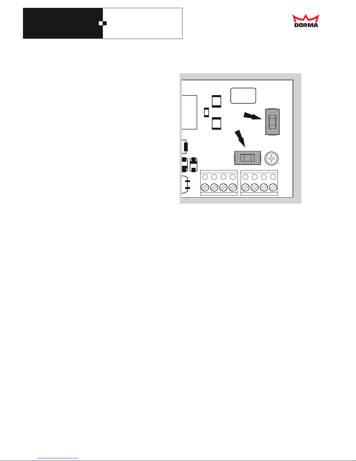
5.1 Fuses
In the event that the fuse (SI101 basic card) needs to be
replaced, there is a spare fuse at the bottom right of the
basic module.
The fuse can be re-ordered using art. no.1900001797488
(Littlefuse 0154.750 DRT, 750mA).
The use of other fuses is not permissible.
SI101
Page 20
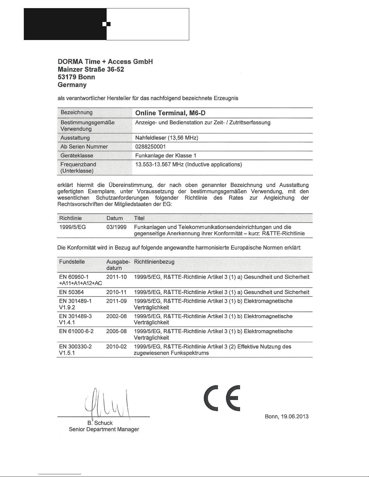
M6D
20
EG Konformitätserklärung
EC Declaration of Conformity
CE Déclaration de conformité
Page 21
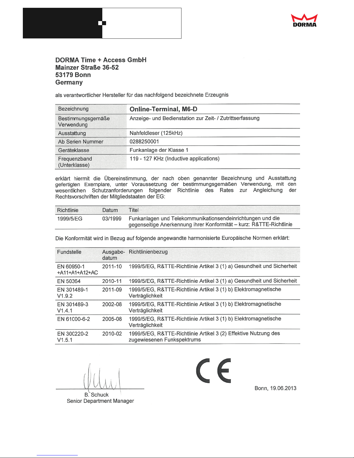
M6D
EG Konformitätserklärung
EC Declaration of Conformity
CE Déclaration de conformité
21
Page 22
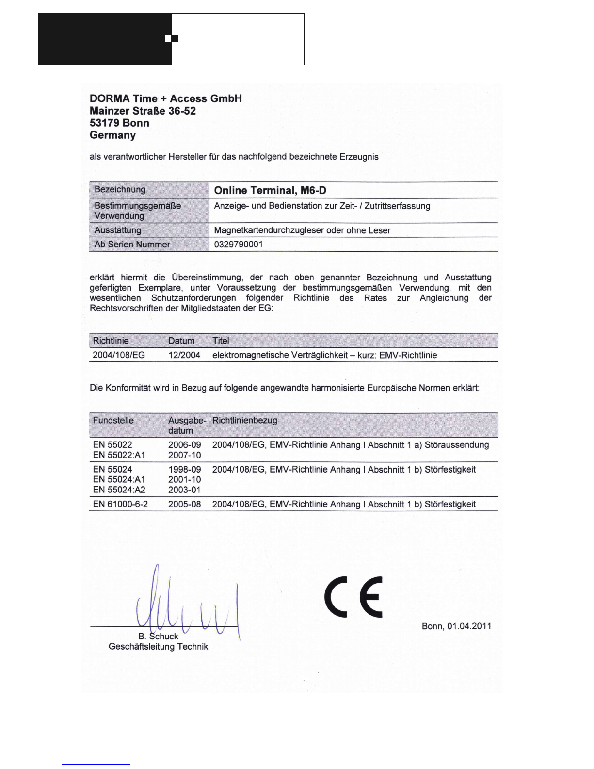
M6D
22
EG Konformitätserklärung
EC Declaration of Conformity
CE Déclaration de conformité
Page 23
23
M6D
Notes
Page 24
M6D
6. Technical data
Technical data for M6D
Power supply
16 V bis 36 VDC (SELV)
16 V bis 24 VAC (SELV)
Power consumption
max. 2.4 W (approx. 100 mA at 24 V)
Read procedure
The following readers can be fitted:
• Swipe reader
• Indala-Trovan
Frequency: 125 kHz
Read distance: up to 8 cm
• Hitag (HITAG1, HITAG2, EM4102, EM4450)
Frequency: 125 kHz
Read distance: up to 4 cm
• Legic prime, Legic advant
Frequency: 13,56 MHz
Read distance: up to 4 cm
• Mifare Classic, Mifare DESFire
Frequency: 13,56 MHz
Read distance: up to 4 cm
Anti-tamper monitoring
available
Interfaces:
RS485
Protocols:
DP1
Display and operating elements
1x LC display with 2x 16 characters, back-lit
1x LED
1x acoustic signal transmitter
1x keyboard (various models possible)
Connection cable
Due to the connection terminals, only lines with a max.
cross-section of 1
mm²
can be connected.
Ambient conditions
Operating temperature range: –20°C bis +50°C
Storage temperature range: –20°C bis +70°C
Humidity range: 0 bis 80%, non-condensing
General design
EN 60 950-1, protection class III
Protection rating
IP30
Resistance to interference
EN 61000-6-2
Immunity of devices in industrial operation
Interference emissions
EN 61000-6-3
Emission standard for residential, commercial and lightindustrial environments
Dimensions
176 x 176 x 55 mm (WxHxD)
Casing colour
Grey/blue RAL2208005
Weight:
approximately 600 g
We reserve the right to make technical modifications and improvements to promote the progress of our equipment.
DORMA Time + Access GmbH Postfach 21 01 85 • D-53156 Bonn • Mainzer Straße 36-52 • D-53179 Bonn
Tel. +49 (0) 2 28/85 54-0 • Fax +49 (0) 2 28/85 84-1 75 • www.dorma-time-access.de
DORMA GmbH + Co. KG Postfach 40 09 • D-58247 Ennepetal • DORMA Platz 1 • D-58256 Ennepetal
Tel. +49 (0) 23 33 / 793-0 • Fax +49 (0) 23 33 / 79 34 95 • www.dorma.com
 Loading...