

Page 1
DORMA
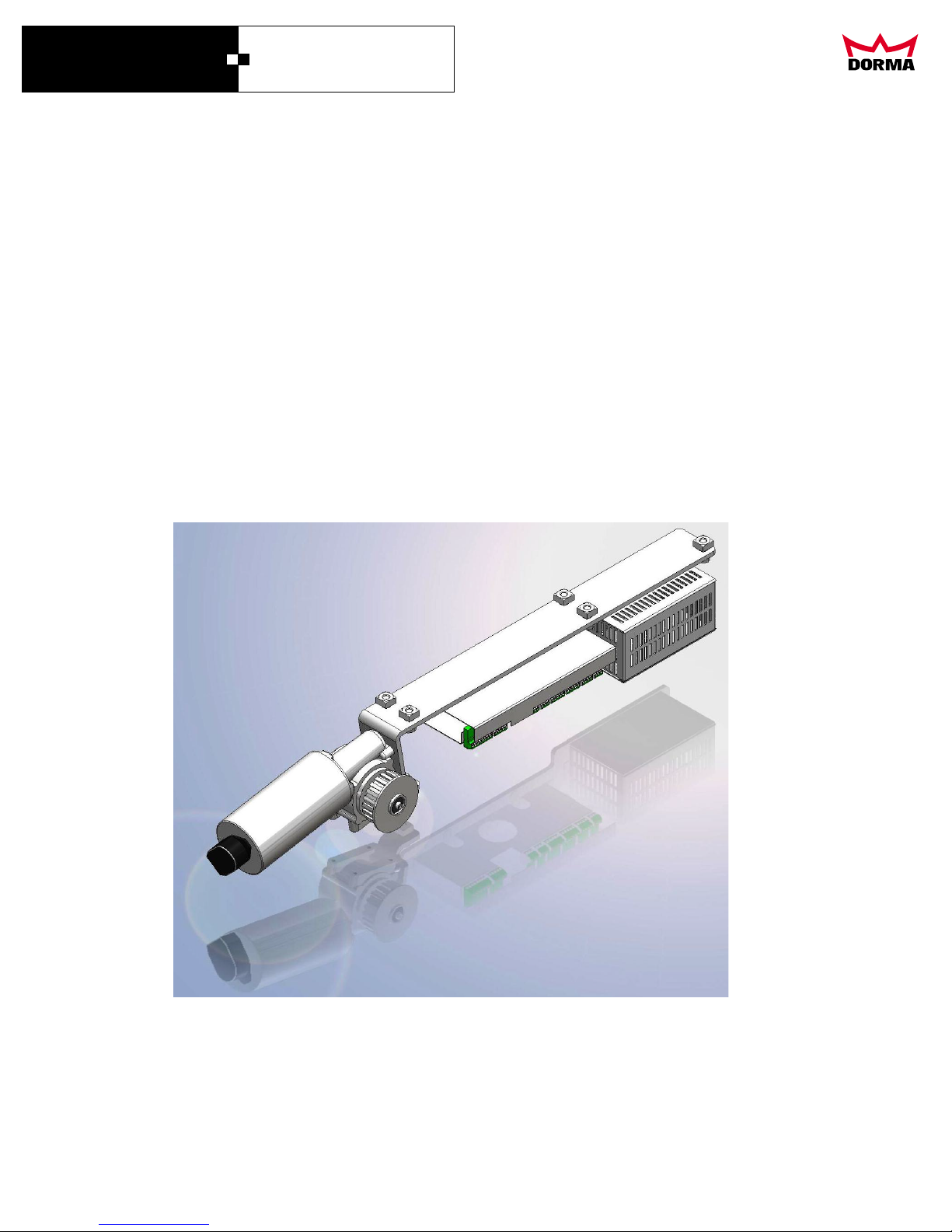
ESA II Controller
and Wiring Manual
ESA II CONTROLLER
AND WIRING MANUAL
DORMA AUTOMATICS, Inc. 924 Sherwood Drive Toll-Free: 877-367-6211 DL2842-010
Lake Bluff, IL 60044 Fax: 877-423-7999 rev. A
E-mail: [email protected] Subject to change without notice
Page 2
DORMA
ESA II Controller
and Wiring Manual
Contents
Page
Contents
Tecnical data
Comissioning
Settings
Function test
Function module
Care and maintenance
Operation instructions
Troubleshooting
Terminal denitions:
Wiring diagrams:
General arrangement
Motor, control system and power supply
Night-/Bank-open
2 safety beams Microcell THREE (BEA)
Without safety beam
Breakout/cuto switch
Without breakout/cuto switch
Battery
Program switch
Motion
detector / presence sensor
(BEA)
Motion detector / presence sensor profusion (Bircher Reglomat)
Panic closing function
Electric lock
Airlock
1
2
3
4
4 - 5
5 - 6
6 - 7
7 - 8
9
10 - 12
13
14
14
15
15
16
16
17
17
18
19
20
21
22
Parameterising
1
DORMA AUTOMATICS, Inc. 924 Sherwood Drive Toll-Free: 877-367-6211 DL2842-010
Lake Bluff, IL 60044 Fax: 877-423-7999 rev. A
E-mail: [email protected] Subject to change without notice
23 - 29
Page 3
DORMA
ESA II Controller
and Wiring Manual
Technical Data
Power supply data
Fuse
Power supply for external accessories
Power consumption: max.
Function programs
Close
AUTOMATIC
PERMANENT OPENING
PARTIAL OPENING
EXIT
Parameter
Opening speed
Closing speed (up to 190 lb)
Creep speed OPENING
Creep speed CLOSING
Brake ramp
Brake ramp CLOSE
Brake ramp reversing
Hold open time
Hold open time NIGHT/BANK
Delayed opening
Partial Opening
Creep speed distance OPENING
Creep speed distance CLOSING
Acceleration OPENING
Acceleration CLOSING
Force limitation
Force limitation CLOSING
OPEN braking deceleration OPEN
NIGHT/BANK
OPENING
120 V +/- 10% 50/60 Hz
6.6 A not exchangeable
27 V DC / 2 A
250 W
· = yes
·
·
·
·
setting range
max.
30 in./s
12 in./s
4 in./s
4 in./s
9
9
9
180 s
60 s
10 s
open
12 inch
12 inch
9
9
70 lb
70 lb
4
4
1
1
10
0
0
min.
in./s
in./s
in./s
in./s
1
1
1
1.5 s
1.5 s
0 s
inch
inch
inch
1
1
11 lb
11 lb
2
DORMA AUTOMATICS, Inc. 924 Sherwood Drive Toll-Free: 877-367-6211 DL2842-010
Lake Bluff, IL 60044 Fax: 877-423-7999 rev. A
E-mail: [email protected] Subject to change without notice
Page 4
DORMA
ESA II Controller
and Wiring Manual
1. Commissioning
1.1 Please note:
Work on electrical equipment may only be
performed by properly qualied electricians.
Power supply (by others) with 15 A fuse protection
must be available.
Power cord must be double-insulated, for example:
Do not use ribbon cable! The maximum cable length
of the external components must not exceed 98 ft.
1.2 Basic requirements:
· The operator is fully assembled.
· The protective earth is connected.
· The safety beams are connected (optional).
· The rechargeable battery pack (optional
is connected.
· Components supplied separately, such as
program panel, activators, radar motion
detectors, Night-/Bank key switches and
connected.
· The end stops are adjusted so that, at maximum
opening with, both active leaves are in contact
with the stops; and when door is closed, neither
panel touches the sealing prole.
1.3 Commissioning
1. Open the sliding leaves half way.
2. Move the program switch to position CLOSE
3. Insure jumper is in place on the breakout or
emergency stop contacts
The door must perform a closing cycle at low
(creep) speed.
If the door performs an opening cycle, the
system must be set back to original settings.
Disconnect the power plug so that the
opening cycle stops.
Proceed on 1.5 original settings
If the door performs a closing cycle, proceed with the
learning cycle starting with the door closed.
Please note:
The safety beams and radar motion detectors are
disabled during the learning cycle, as it has to be
performed without interruptions.
In case that a fault or error should occur during this
procedure, the learning cycle will be interrupted
needs to be re-started.
1.4 Performing the learning cycle:
Press SERVICE/SELECT button until one of the
external until each one of the display
illuminates in turn.
· The door has to run smoothly.
· The door accelerates in order to determine the
door weight.
· The door opens at low (creep) speed to determine
the opening width.
· The opening parameters are now stored and an
8 ashes twice on the 7-segment display.
The learning cycle is now complete.
· The 7-segment display indicates a dot.
· The door closes at normal speed.
Test of opening cycle
Set program switch to AUTOMATIC and push the
SERVICE/SELECT button
closed after the hold-open time expires.
The following door parameters must be checked
and amended if required.
Settings: See operating instructions of adjustment.
Perform amendments with the aid of the parameterization
instructions and the 7-segment display on the control unit
or via PDA.
Menu A.:
Emergency operation (via rechargeable battery pack)
- original settings = 0
Menu r.:
Locking action depending on position of program switch
- original settings = 1
Menu L.:
Locking type original settings = 1
The locking type is not learned automatically during the learning cycle.
1.5 General information concerning the original settings.
If several settings have been changed, the door no longer
works properly, reset to original settings
· The door performs an opening cycle and is
· Set program switch to CLOSE
· Open the door leaves to 50%
· Connect power plug.
· Press and hold the service key.
· As soon as the power supply has been switched on,
the control unit powers up and the security checks are
performed.
An 8 is shown on the seven-segment display. When the
8 blinks twice, the original settings have been restored.
· In case the door starts an opening cycle, press the minus
button on the control unit to change the direction of the motor.
· Following the restoring of the original settings, diering
settings (e.g. locking type) have to be made manually either
via the buttons on the control unit or via the PDA
(parameterization) and a learning cycle has to be performed
(see 1.4)
3
DORMA AUTOMATICS, Inc. 924 Sherwood Drive Toll-Free: 877-367-6211 DL2842-010
Lake Bluff, IL 60044 Fax: 877-423-7999 rev. A
E-mail: [email protected] Subject to change without notice
Page 5
DORMA
ESA II Controller
and Wiring Manual
2. Settings
The control unit is preset, i.e. If you require another
setting, you will have to implement this either with the
aid of the buttons of the 7-segment display on the
control unit (see adjustment instructions),
or via the PDA.
3. Function test
Please note:
All connected sensors must be checked in every
program switch position.
sensors
The must be set according to the respective
installation instructions/documentation texts.
3.1 Safety beams (Optional-not required)
Automatic safety beam self-check
(internal test via control unit)
The safety beams are automatically tested before
each closing cycle. If the test fails (the door does not
close) the system must be checked by a service
engineer.
The passage between the sliding leaves is monitored
by safety beams . If a person or an object enters the
passage or detection range of the safety beams, a
closing cycle is reversed to an opening cycle and the
door remains open until the monitored area is free and
the hold-open time has expired.
Manual safety beam check…
During closing cycle:
Interrupt one safety beam after the other during the
closing cycle.
The respective LED on the control unit goes out
·
and the door reverses.
While the door is open:
Interrupt the safety beams for several seconds while
the door is open.
The door should remain open for as long as the
·
safety beams are interrupted.
Once the safety beams are uninterrupted,
·
the door should close on expiry of the preset
hold-open time.
3.2 External activation sensor
Activation sensors are mostly radar sensors
responding to movements. The system is activated by
approaching people or objects.
Function test.
Basic requirements:
The external activation sensor is connected and the
program switch is set to AUTOMATIC or
PARTIAL OPEN position.
Function:
If a person or an object a
the door opens, and then closes on expiry of the holdopen time.
ects the range of the sensor,
3.3 Internal activation sensor
Function test.
Basic requirements:
The internal must be connected and
the program switch must be set to AUTOMATIC,
EXIT ONLY or PARTIAL OPEN position.
Function:
If a person or an object a
the sensor, the door opens, and then closes on expiry
of the hold-open time.
3.4 Night-/ Bank Function
Function test.
Basic requirements:
The Night-/ Bank contact is connected and the
program switch is set to CLOSE.
Function:
Activate the system with the .
The door is unlocked and opens.
·
Once the user has passed the door or on expiry
·
of a
locks in the closed position.
3.5 Breakout Switch
Function test.
Basic requirements:
The program switch must be set to AUTOMATIC,
PARTIAL OPEN, EXIT ONLY, CLOSE (not locked) or
PERMANENT OPEN.
Function:
Breakout any panel.
The door leaves stop immediately
·
The door can be moved manually.
·
3.6 Locking device
The door is in close position, it is locked, when the
program switch is set to OFF, AUTOMATIC or
EXIT ONLY.
3.7 Monitoring of closing and opening force
Obstruction during closing cycle:
If the door leaves run up against an obstruction during
the closing cycle, the closing cycle is reversed into an
opening cycle. The door opens to its full width. The
door then closes at low (creep) speed until the hold
open time expires. This sequence is repeated until
the obstruction is removed.
Obstruction during opening cycle:
If the door leaves open against an obstruction, the
door stops, then performs a further opening attempt at
low (creep) speed. If the obstruction is still present, the
door stops again. After a total of six opening attempts
the door closes. Once the obstruction is removed, the
next opening cycle is performed at low (creep) speed.
Then the door resumes operation at the preset speed.
activation sensor
ects the detection range of
Night-/ Bank contact
d hold-open time, the door closes and
4
DORMA AUTOMATICS, Inc. 924 Sherwood Drive Toll-Free: 877-367-6211 DL2842-010
Lake Bluff, IL 60044 Fax: 877-423-7999 rev. A
E-mail: [email protected] Subject to change without notice
Page 6
DORMA
ESA II Controller
and Wiring Manual
3.8 EMERGENCY OPEN FUNCTION in the event of
a power failure
Basic requirements:
The rechargeable battery pack (optional) is connected
and the EMERGENCY OPEN FUNCTION is set.
In the event of a power failure:
If the program switch is in CLOSE position:
The door remains closed.
·
If the program switch is in AUTOMATIC, PARTIAL
OPEN or EXIT ONLY position:
An automatic emergency opening is performed.
·
The door is opened with the aid of the
·
rechargeable battery pack (optional).
The door may be manually unlocked and opened from
the inside.
3.9 EMERGENCY CLOSING in the event of a
power failure
Basic requirements:
The rechargeable battery pack (optional) is connected
he EMERGENCY CLOSING FUNCTION is set.
and t
Function:
Set the program switch to AUTOMATIC, EXIT ONLY,
PARTIAL OPEN or PERMANENT OPEN position.
The door is in open position.
Remove the power plug (power failure).
The door performs a complete closing cycle with
·
the aid of the rechargeable battery pack.
3.10 EMERGENCY OPERATION in the event of a
power failure.
Basic requirements:
The EMERGENCY OPERATION FUNCTION is set
and the rechargeable battery pack (optional) is
connected.
Function:
As soon as the system is activated the sliding leaves
move at low (creep) speed.
Furthermore all functions remain operational until the
rechargeable battery pack (optional) is empty.
3.11 Safeguarding of door:
The safety measures to safeguard the doors must be
made in accordance with the local
regulations.
4. Function module
Additional functions may be set/selected with the aid
of the function module.
The following additional functions are available:
Securing the closing edges
·
·
Panic Closing Function
·
Door status contacts
·
Airlock Function
The functions may be connected via two di
DCW address.
erent
DCW address 48
The system must be disconnected from
power supply while the DCW address of the
function module is set.
Setting the DCW address:
Set both DIP switches of the function module to CLOSE
position.
The DCW address 48 is now set.
4.1 Securing the secondary closing edges with
the ”DCW address 48” (IN 1 and IN 2) (See
connection diagram of function module.)
Presence sensors monitor the side lite safety area.
(For example the opening cycle towards the wall for
systems without safety screens.)
If a person or an object enters the detection range of
the according secondary closing edge sensor, the
opening cycle is stopped (n=0).
to n=1, the door opens at low (creep) speed.
The leaves continue opening at normal speed after the
obstruction has been removed.
Securing the main closing edge (IN3)
(See connection diagram of function module)
Presence sensors monitor the passage between the
sliding leaves in their closing direction.
If a person or an object is within the detection range of
the presence sensor, the closing cycle is reversed into
an opening cycle.
4.2 Setting the Panic Closing Function (IN 4)
see wiring diagrams of function module
The Panic Closing Function is subject to
special legal provisions, therefore the
provisions of the relevant country have to be
observed.
The Panic Closing Function has to be set via
the PDA for safety reasons.
The Panic Closing Function must be triggered
via safety deactivation (Totman system).
Basic requirements:
The Panic Closing Function must be set.
Function:
Press and hold the push button to close the door.
The door only performs a closing cycle while the
·
push button is pressed.
The door will close immediately (it will even stop
·
an opening cycle).
The safety functions: blocking sensor, safety
·
beams and radar motion detectors are
deactivated.
The door closes and locks.
·
Should the door be blocked by a person or an
·
obstacle during this closing cycle, the door will
close with maximum force.
In this mode the door will not respond to an
·
activation via NIGHT-/BANK, INTERNAL, or
EXTERNAL SENSORS.
When the menu is set
5
DORMA AUTOMATICS, Inc. 924 Sherwood Drive Toll-Free: 877-367-6211 DL2842-010
Lake Bluff, IL 60044 Fax: 877-423-7999 rev. A
E-mail: [email protected] Subject to change without notice
Page 7
DORMA
ESA II Controller
and Wiring Manual
This procedure is only stopped when the motor is
·
overloaded. The motor will switch o for 10
seconds after 10 seconds of constant operation.
On expiry of the 10-second break, the closing
action is repeated until the door closes and locks
successfully (the blocking is removed).
If the motor overloads, this error may be
·
acknowledged by setting the program switch to
CLOSE position. This reset
order to enable a
Resetting the Panic Closing Function
The program switch has to be set to CLOSE position.
The system has now quit the Panic Closing
·
Function.
By setting the program switch to CLOSE position,
·
the control unit resumes the normal functions.
4.3 Door status contacts see connection diagram
Door status contact 1 (OUT-1)
The relay contact is closed when the door performs an
opening cycle, is in "open position" or performs a
closing cycle.
Door status contact 2 (OUT-2)
The relay contact is closed when the door is in the
"closed position".
Door status contact 3 (OUT-3)
The relay contact is closed in the event of a
malfunction.
Door status contact Bell contact (OUT-4)
The relay contact is closed when one or both safety
beams are interrupted. The function is deactivated
when the door is closed.
prompt response of the door.
s the waiting period in
(default "door open")
(default "door closed")
(default "malfunction")
DCW address 49
The system must be disconnected from
power supply while the DCW address of the
function module is set.
Setting the DCW address:
Set DIP switch 1 of the function module to ON position
and DIP switch 2 to CLOSE position.
The DCW address 49 is now set.
4.4 Disabling the airlock (IN 3)
As soon as the airlock function is activated while the
door is still closed INTERNAL and EXTERNAL
ACTIVATION SENSOR signals are blocked.
An opening or closing cycle cannot be interrupted. All
airlock functions are realized via direct wiring (no bus
connection). The di
as follows:
erent functions may be realised
Airlock function:
Door 2 is disabled during the opening cycle of
door 1. (internal and external are
deactivated.)
The locking function is disabled as soon as the door is
closed.
Door 1 is locked during the opening cycle of door 2.
internal and external activation sensors
deactivated.)
The locking function is disabled as soon as the door is
closed.
4.5 Door status contact 2 (OUT 2)
(Disabling of airlock if required)
The relay contact is closed as soon as the door starts
an opening cycle. (Same function as function module
with ”DCW address 48”.)
4.6 Panic Closing Function (IN 4) &
Door status contact 1 (OUT 1)
Same function as function module with
“DCW address 48”.
4.7 Bell contact (OUT 4)
The relay contact is closed when one or both safety
beams are interrupted. This function is deactivated
when the door is closed.
activation sensors
era(
5. Care and maintenance
The unit must be checked and, if necessary, serviced
before it is commissioned for the
thereafter as required, but at least once a year
by a specialist engineer or by authorised specialist
personnel.
Wear parts:
The following wear parts must be checked in regular
intervals and replaced if required in order to ensure
the smooth function of the unit.
Track rollers every 2 years
·
Rechargeable battery pack every 3 years
·
Rubber end stops at every service check
·
Track rail every 5 years
·
Toothed belt every 1,000,000 opening/closing
·
cycles
Floor guides at every service check
·
Brushes (optional)
·
We recommend to conclude a maintenance
contract with DORMA.
Cleaning:
During cleaning, the program switch must be set to
CLOSE or PERMANENT OPEN in order to avoid
inadvertent movement
The entire sliding door unit (aluminium, glass, covers)
can be cleaned with a damp cloth and normal
commercial detergents. The safety beams have to be
cleaned with a dry cloth and the
be cleaned.
s of
the door.
t time and
r guide rails must
6
DORMA AUTOMATICS, Inc. 924 Sherwood Drive Toll-Free: 877-367-6211 DL2842-010
Lake Bluff, IL 60044 Fax: 877-423-7999 rev. A
E-mail: [email protected] Subject to change without notice
Page 8
DORMA
ESA II Controller
and Wiring Manual
Service display
The service display informs the facility operator that
the door system has to be serviced.
The maintenance intervals can be adjusted via PDA.
Either a time slice (monthly interval, e.g. every 6
months) and/or a certain number of opening/closing
cycles can be selected (e.g. following 80,000
opening/closing cycles).
Depending on the selected interval, the service display
blinks as follows:
Max. number of adjusted opening/closing cycles
reached:
Display illuminates permanently.
·
Time interval expired:
Display blinks (every 0.5 seconds).
·
Time and opening/closing cycle interval reached:
Display illuminates permanently for 10 seconds,
·
then it blinks for 10 sec.
Test cycle
With the aid of the PDA, a test cycle may be
performed in order to optimise the smooth
performance of the door.
Following successful commissioning and functional
testing of the unit, the documentation has to be
handed over to the facility operator and a
to be made.
g has
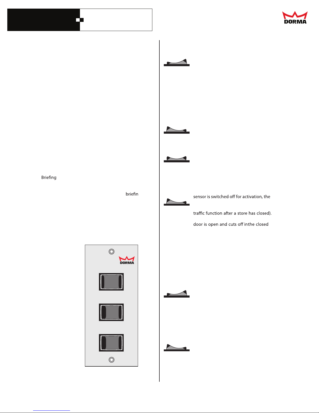
6. Operation instructions
6.1 Program switch
The program switch is installed in one of the vertical
door jambs. The following functions can be selected
using the three toggle switches:
CLOSE
Main Switch
AUTO
I O II
OPEN
Main Switch
Switch is in position:
AUTO
OPEN
CLOSE
Switch - EXIT ONLY
(Main Switch is in AUTO position)
Switch is in position:
ON
CLOSE
When an activation signal is received at
either Radar 1, (assuming the EXIT
ONLY switch described below is “CLOSE”),
and/or Radar 2 inputs, the door will
open. After opening, signals received
from the Presence input or the Safety
Beams, will cause the door to remain
open, open again when the door is
closes.
After all the sensors have cleared, the
hold open delay is initiated, and when it
expires, the door will close.
Continuous Open Operation
The door opens to the full opening width
and remains in this position. Manual
operation of the door is possible, with
some resistance from the operator.
The door stops immediately when the
switch is placed in this position.
operation of the door is possible, with
some resistance from the operator.
In this position the exterior motion
door can only activated from the
interior motion detector (e.g. one-way
The exterior Radar 1 is active while the
position.
When an activation signal is detected
from the interior (Radar 2), the door
opens, delays according to the hold
open time setting, then closes.
If, in addition, the Partial Open Switch is
set to the ON position, the door opens
only to the predetermined partial open
position and closes after the expiration
of the hold open delay.
The Exit Only function is switched to “CLOSE”.
Manual
be
EXIT ONLY
OFF
Exit Only
PARTIAL OPEN
OFF
Partial Open
7
DORMA AUTOMATICS, Inc. 924 Sherwood Drive Toll-Free: 877-367-6211 DL2842-010
Lake Bluff, IL 60044 Fax: 877-423-7999 rev. A
E-mail: [email protected] Subject to change without notice
ON
ON
Switch - PARTIAL OPEN
(Main Switch is in the AUTO position)
PARTIAL OPEN Switch is in position:
ON
If the Partial Open Switch is set to the
ON position, the door opens only to the
predetermined partial open position and
closes after the expiration of the hold
open delay. If, in addition, the EXIT
ONLY switch is in the ON position, then
the door can be activated only from the
interior devices; the exterior motion
detector is switched to close.
Page 9

DORMA
ESA II Controller
and Wiring Manual
6.2 Setting the PARTIAL OPEN width
The PARTIAL OPEN width can be adjusted with the
PDA. The PDA can also be used to disable the setting
via program switch, so that settings can only be made
with the PDA.
The opening width of the door can be adjusted
individually. Starting from the full opening width, a
reduced opening width = partial opening width
may be set (e.g. in winter to reduce drafts.)
1. Close the door.
2. Set program switch to PERMANENT OPEN
The door opens at low (creep) speed.
·
3. As soon as the door reaches the desired partial
opening width, set the program switch to
PARTIAL OPEN and the main switch to close.
The door stops
·
The control unit stores the desired position.
·
The door performs a closing cycle.
·
6.3 Emergency Breakout
The program switch is set to AUTOMATIC, PARTIAL
OPEN or EXIT ONLY.
Breakout any panel:
·
The door stops immediately
· The leaves may be moved manually.
6.4 Start-up following a power failure
After a power failure, the control unit performs a selfcheck of approx. 5 sec. for safety reasons.
The door then closes at low (creep) speed and
resumes the preset program function.
8
DORMA AUTOMATICS, Inc. 924 Sherwood Drive Toll-Free: 877-367-6211 DL2842-010
Lake Bluff, IL 60044 Fax: 877-423-7999 rev. A
E-mail: [email protected] Subject to change without notice
Page 10
DORMA
ESA II Controller
and Wiring Manual
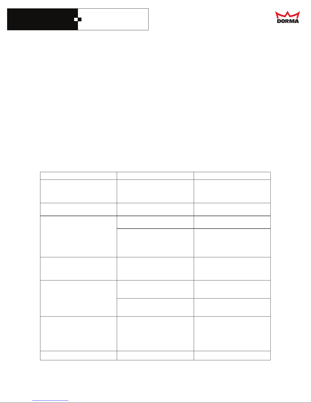
7. Troubleshooting
How does the control unit respond to a short circuit?
The 27 V power supply for radar motion detectors, the locking device etc. is short circuit proof. In the event of a short circuit,
both control LED lights of the safety beams go out and the 7-segment display indicates error 3 (program switch) Once the
short circuit is removed, the 27 V power supply is restored automatically.
·
Have all maintenance intervals been observed/has the maintenance been performed?
·
Have all wear parts been checked and replaced if required?
·
Is the power supply connected?
·
Is the Breakout Switch making contact?
·
Is the program switch set correctly?
·
Are the areas monitored by the clear and clean?
·
Is the door blocked by an obstruction?
·
Is the door running smoothly (counter rollers, oor guides)?
·
Are all external activators, EMERGENCY OFF push button, program switch and locking device
connected correctly?
·
All connection points checked?
·
Is the rechargeable battery pack correctly connected?
For further assistance, consult the following troubleshooting table.
Should you perform installation work, disconnect the power plug and the battery pack in order to keep the
control unit voltage-free. After a fault is redeemed, the error code must be deleted.
Reset error codes:
Set program switch to CLOSE.
safety beams
Fault
Door runs jerkily and out of control
Door remains open after cyclic
self-check (every 4 hours).
Door remains open, in all
program switch settings
Door remains open in the program
switch settings: AUTOMATIC,
PERMANT OPENING, and
PARTIAL OPENING
Basic module indicates error ”1”
(obstruction during commissioning)
Door does not open when the program
switch is set to: AUTOMATIC, EXIT
ONLY, PERMANT OPEN, and
PARTIAL OPEN
Unpleasant operating noise
Possible causes
The incremental encoder cable is
defective
The connector cable is not xed
properly
The rechargeable battery pack is not
fully recharged or empty
Safety beams eected
EMERGENCY OFF push button
Detector is emitting a continuous signal
The learning cycle has not been
performed (the door weight is still
undetermined)
The obstruction detection is too
sensitive for the door set (e.g. small,
high and heavy door leaves)
External and internal motion sensor
Screw presses against track roller
Remedy
Replace cable
Fit connector cable properly
Check battery voltage
Change rechargeable battery pack
safety beams
Check function with the
help of the LED on the basic module.
Short the connector inputs. If fault is
cured by this, check EMERGENCY
OFF push button, and exchange if
necessary, then check with the help of
the PDA.
Remove connector of sensor motion. If
fault is cured by this, replace it
Perform learning cycle
Adjusting the
force limitation (OPEN, CLOSE) and
the delay time via the PDA
Remove activator connector and short
the input. If the fault is cured by this,
check supply voltage (27 V) of the
basic module and the sensors. If it is
okay check and replace sensors if
required.
Replace or trim screw
obstruction detection via
9
DORMA AUTOMATICS, Inc. 924 Sherwood Drive Toll-Free: 877-367-6211 DL2842-010
Lake Bluff, IL 60044 Fax: 877-423-7999 rev. A
E-mail: [email protected] Subject to change without notice
Page 11
DORMA
ESA II Controller
and Wiring Manual
1
3
2
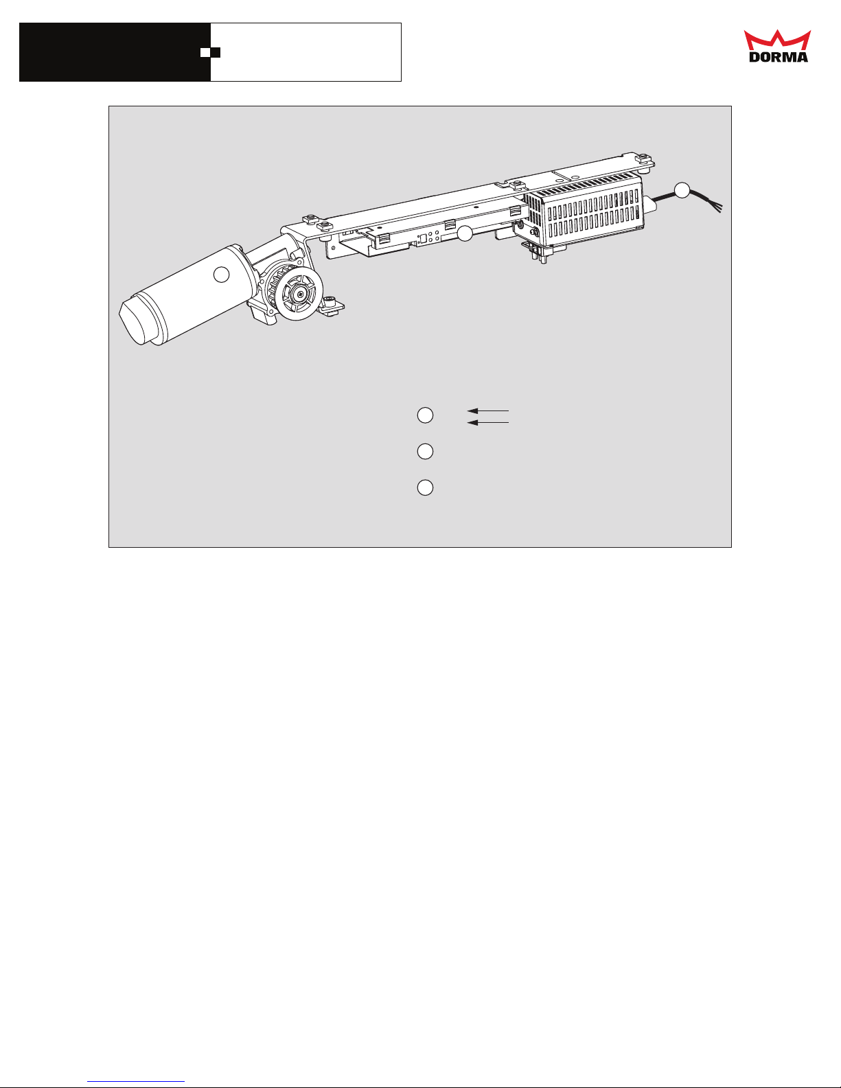
Description and
terminal connections
1
2
3
120 V AC
Mains supply
Motor
Control system
10
DORMA AUTOMATICS, Inc. 924 Sherwood Drive Toll-Free: 877-367-6211 DL2842-010
Lake Bluff, IL 60044 Fax: 877-423-7999 rev. A
E-mail: [email protected] Subject to change without notice
Page 12
DORMA
ESA II Controller
and Wiring Manual
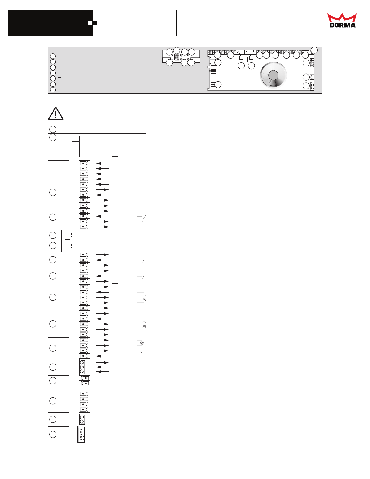
Control System basic module
1
LED 1
2
LED 2
3
7-Segment-display menu navigation
4
+ "Plus" push button
5
6
7
"Minus" push button
SEL "Select" push button
SERV“Service” push button
When connecting a DCW device via cable, the wiring has to be checked again.
Interchanged DCW connections (e.g. 27 V DC to A or B), or missing GND connection,
may destroy all connected DCW devices.
8
10
11
12
13
14
15
16
17
18
19
20
21
22
23
9
48
47
46
45
1
2
3
4
5
6
7
8
9
10
11
12
13
14
15
16
17
18
19
20
21
22
23
24
25
26
27
28
29
30
31
32
33
34
35
36
37
38
39
40
41
42
43
44
+ 27 V DC
Signal A
Signal B
GND
GND
GND
+ 27 V DC
GND
+ 27 V DC
GND
+ 27 V DC
GND
+ 27 V DC
+ 27 V DC
GND
+ 27 V DC
+ 27 V DC
GND
+ 27 V DC
GND
+ 35 V DC
+ 27 V DC
Signal A
Signal B
GND
3
4
2
1
7
5
6
10
9
8
Description and terminal diagram
FST - Interface
DCW - Interface
Program switch
Locking device
CLOSE
AUTOMATIC
EXIT ONLY
PARTIAL OPEN
PERMANENT OPENING
GND
NIGHT / BANK
GND
Power supply
Lock
Status report
Unlock
GND
Interconnection LON-Adapter
Service interface to PDA
External activation
Internal activation
Presence 2
Presence 1
Service
Breakout
Power supply
Battery
Power supply
External detector
GND
Power supply
Internal detector
GND
Power supply
Receiver 2
Power supply
Transmitter 2
GND
Power supply
Receiver 1
Power supply
Transmitter 1
GND
Service outlet (open Source, 1,5A)
Power supply
GND
EMERGENCY OFF
Inhibit
GND
Power supply
Battery +
Battery -
DCW Interface
Motor
Incremental encoder
11 14
13
12
15 16
20
19
18
17
21
22
23
11
DORMA AUTOMATICS, Inc. 924 Sherwood Drive Toll-Free: 877-367-6211 DL2842-010
Lake Bluff, IL 60044 Fax: 877-423-7999 rev. A
E-mail: [email protected] Subject to change without notice
Page 13
DORMA
ESA II Controller
and Wiring Manual
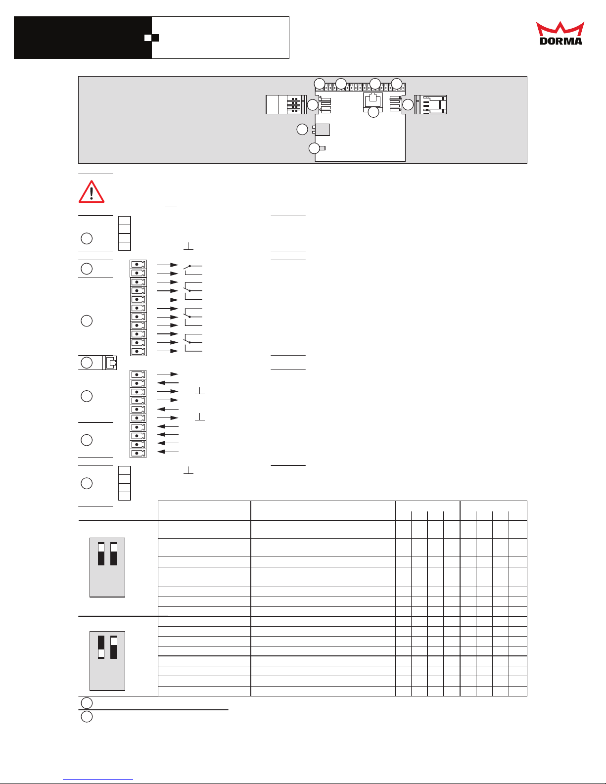
Control system function module
Breaking capacity of digital outlets:
1A 30V DC
0,5 A 125V AC
0,3 A 60V DC
4
3
1
2
2
1
7 8
6
5
Description and terminal diagram
When connecting a DCW device via cable, the wiring has to be checked again.
Interchanged DCW connections (e.g. 27 V DC to A or B), or missing GND connection,
may destroy all connected DCW devices.
9
29
28
3
4
5
6
7
8
9
DCW Adresse 48
27
26
1
2
3
4
5
6
7
8
9
10
11
12
13
14
15
16
17
18
19
20
21
22
23
24
25
1 2
ON
DCW Adresse 49
+ 27 V DC
Signal A
Signal B
GND
+ 27 V DC
IN
+ 27 V DC
IN
IN +
IN IN +
IN -
GND
Signal B
Signal A
+ 27 V DC
C
NO
NC
C
NO
NC
C
NO
NC
C
NO
GND
GND
DCW Interface
OUT 1
OUT 2
OUT 3
OUT 4
COM 1
IN 1
IN 2
IN 3
IN 4
DCW Interface
Digital outputs
Programming interface
Digital inputs
Original settings
Secondary closing edges
Sensor 1
Secondary closing edges
Sensor 2
Main closing edge
Panic closing function
Door status contact 1 “DOOR OPEN”
Door status contact 2 “DOOR CLOSED”
Door status contact 3 “OPERATIONAL FAULT”
Door status contact 4 Bell contact
Digital inputs Digital outputs
1 2 3 4 1 2 3 4
X
X
X
X
X
X
X
X
Disable airlock Entrance (disables the door)
Panic closing function
1 2
ON
2
1
Door status contact 5 Door closed
Door status contact 6 Disable airlock (exit)
Door status contact 7 Airlock impulse (exit)
Door status contact 8 Bell contact
DIP switch
LED status indicator
X
X
X
X
X
X
12
DORMA AUTOMATICS, Inc. 924 Sherwood Drive Toll-Free: 877-367-6211 DL2842-010
Lake Bluff, IL 60044 Fax: 877-423-7999 rev. A
E-mail: [email protected] Subject to change without notice
Page 14
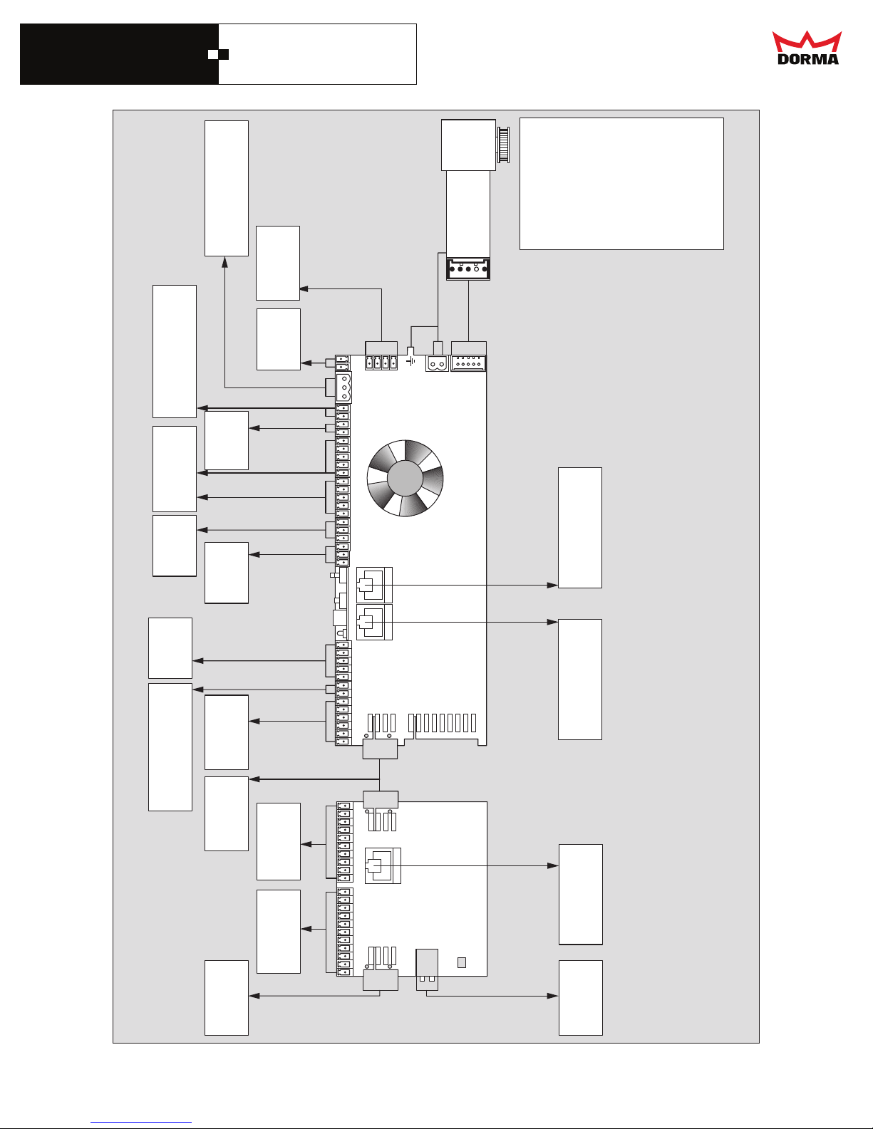
DORMA
ESA II Controller
and Wiring Manual
knip-yergKPYG
nworbNB
wolleyEY
gnihctiwsV53
ylppusrewop
neergNG
etihwHW
yergYG
knipKP
Motor
WCD
Interface
FFO-ycnegremE
yrettaB
hctiws
38
37
36
35
34
33
32
ecivreS
smaebytefaS
radaR
edisni
yalpsid
edistuo
radaR
31
30
29
28
27
26
25
24
23
22
21
20
19
18
17
16
15
14
_
_
ASEmetsyslortnoC II-
ecafretnIecivreS
ADP
teloivTV
kcalbKB
eulbUB
derDR
gnikcoL
nepo-knaB/-thgiN
margorP
hctiws
3TK‘
WCD
tupnilatigiD
Interface
tuptuolatigiD
WCD
13
12
11
10
9
8
7
6
5
4
3
2
1
21
20
19
18
17
16
15
14
13
12
11
10
9
8
7
6
5
4
3
2
1
1
eludomnoitcuF
2
noitcennocretnI
retpadA-NOL
ecafretni
margorP
hctiwsPID
Interface
13
DORMA AUTOMATICS, Inc. 924 Sherwood Drive Toll-Free: 877-367-6211 DL2842-010
Lake Bluff, IL 60044 Fax: 877-423-7999 rev. A
E-mail: [email protected] Subject to change without notice
Page 15
DORMA
ESA II Controller
and Wiring Manual
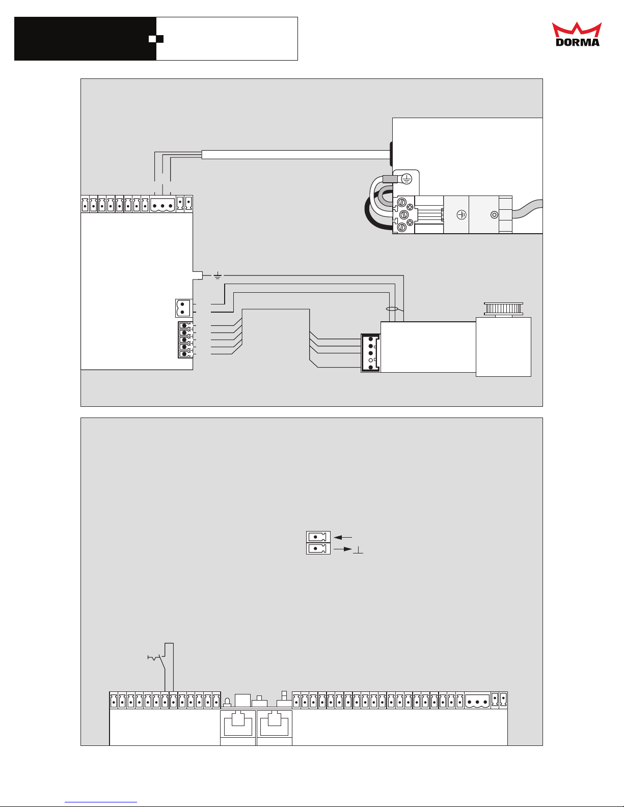
Wiring diagram of the motor, control system and power supply
_
Control system ESA - II basic module
_
35 V DC
Power supply
BK
YE RD
62
72
82
92
03
13
23
33
73
43
83
53
63
BK
BN
WH
1
YE
GN
BN
BL
5
WH
Wiring diagram Night-/Bank-open
120 V AC
60 Hz
N
L
Incremental encoder Motor
Description and
terminal connections
Control system
7
8
GND
Control system ESA - II basic module
11
01
21
1
2
3
4
5
6
9
7
8
31
14
DORMA AUTOMATICS, Inc. 924 Sherwood Drive Toll-Free: 877-367-6211 DL2842-010
Lake Bluff, IL 60044 Fax: 877-423-7999 rev. A
E-mail: [email protected] Subject to change without notice
41
51
61
71
81
91
02
12
22
NIGHT-BANK-contact
_
_
32
42
52
62
72
82
92
03
13
23
33
43
53
63
73
83
Page 16
DORMA
ESA II Controller
and Wiring Manual
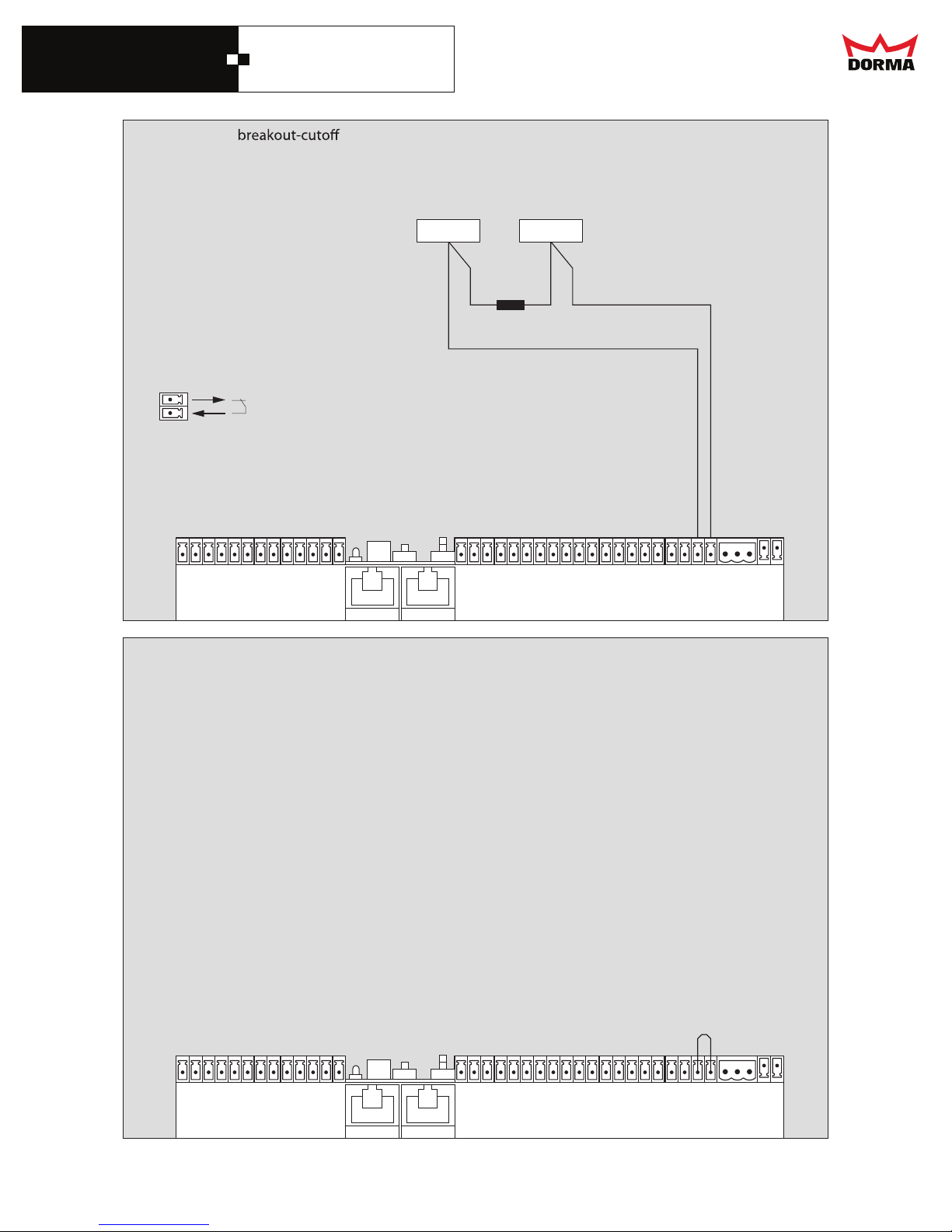
Wiring diagram switch (optional)
Description and
terminal connections
Control system
32
33
_
Control system ESA - II basic module
_
Magnetic switch
Bipart dual magnets shown
(single magnet for single slide)
11
01
21
1
2
3
4
5
6
7
8
9
31
Wiring diagram without breakout-cuto switch
41
51
61
71
81
91
02
12
22
32
42
52
62
72
82
92
03
13
43
53
63
73
23
33
83
_
Control system ESA - II basic module
1
2
3
4
5
_
11
01
21
6
7
8
9
31
41
51
61
71
81
91
02
12
22
32
42
52
62
72
82
92
03
13
43
53
63
73
23
33
83
15
DORMA AUTOMATICS, Inc. 924 Sherwood Drive Toll-Free: 877-367-6211 DL2842-010
Lake Bluff, IL 60044
Fax: 877-423-7999 rev. A
Page 17
DORMA
ESA II Controller
and Wiring Manual
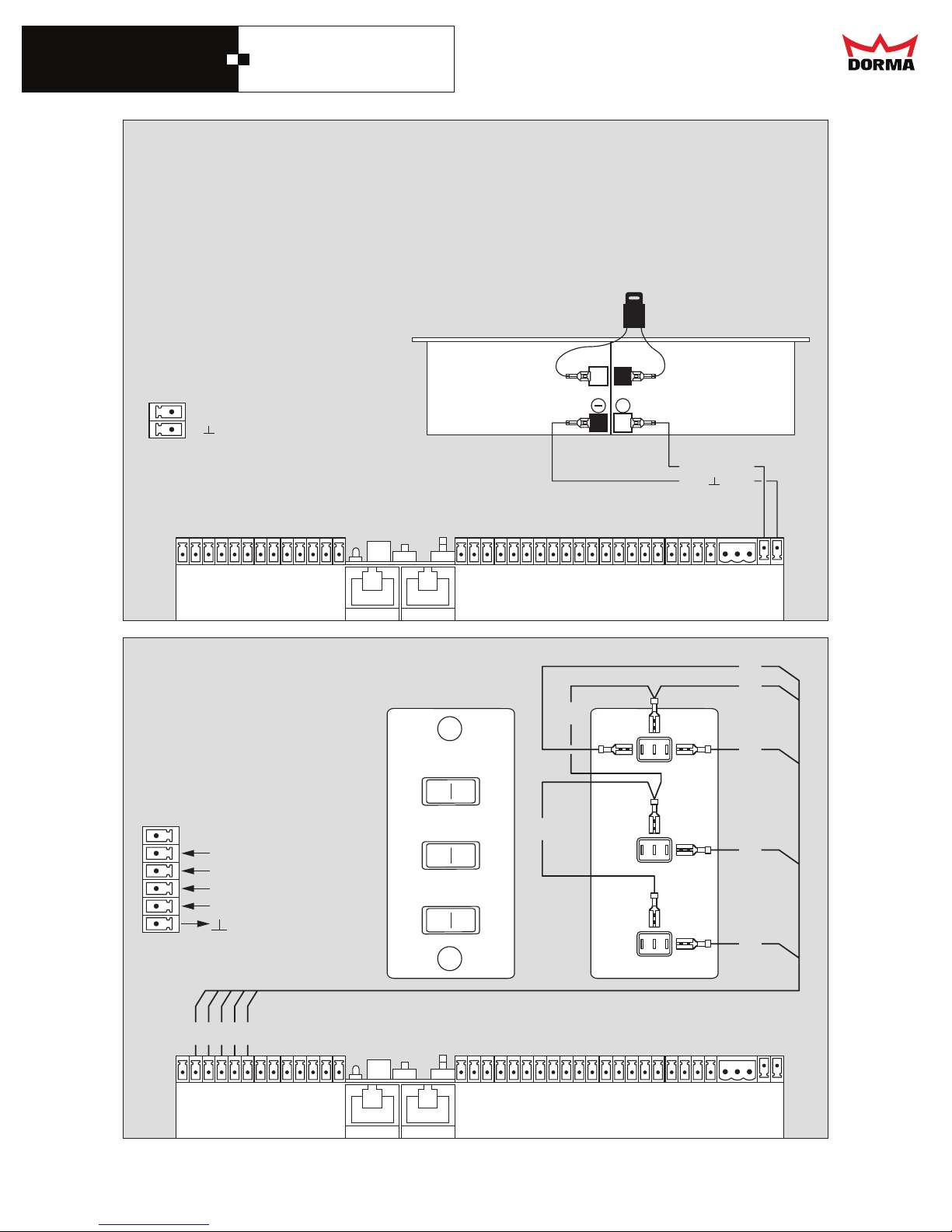
Wiring diagram of the battery (optional)
Description and
terminal connections
Control system
37
38
+27 V DC
GND
Battery
Control system ESA - II basic module
1
2
3
4
5
6
01
7
8
9
11
Wiring diagram Program switch
Battery:
··Attach ONLY for the functional test and
immediately before the commissioning.
Disconnect the battery before servicing the ESA - II
Fuse 10A
Battery
+
BNWH+27 V DC
GND
21
31
41
51
61
71
81
91
02
12
22
32
42
52
62
72
82
92
03
13
23
33
43
53
63
73
83
GN
BK
BK
Description and
terminal connections
AUTO
CLOSE
OPEN
BN
Control system
1
2
3
4
5
6
RD
GN
1
2
3
AUTOMATIC
EXIT ONLY
PARTIAL OPENINGl
PERMANENT OPEN
GND
BK
BN
WH
7
8
4
5
9
6
01
21
31
11
EXIT ONLY
OFF
PARTIAL OPEN
OFF
41
51
16
DORMA AUTOMATICS, Inc. 924 Sherwood Drive Toll-Free: 877-367-6211 DL2842-010
Lake Bluff, IL 60044 Fax: 877-423-7999 rev. A
E-mail: [email protected] Subject to change without notice
BK
ON
ON
Control system ESA - II basic module
61
71
81
91
02
12
22
32
42
52
62
72
82
92
03
13
RD
WH
23
33
43
53
63
73
83
Page 18
DORMA
ESA II Controller
and Wiring Manual
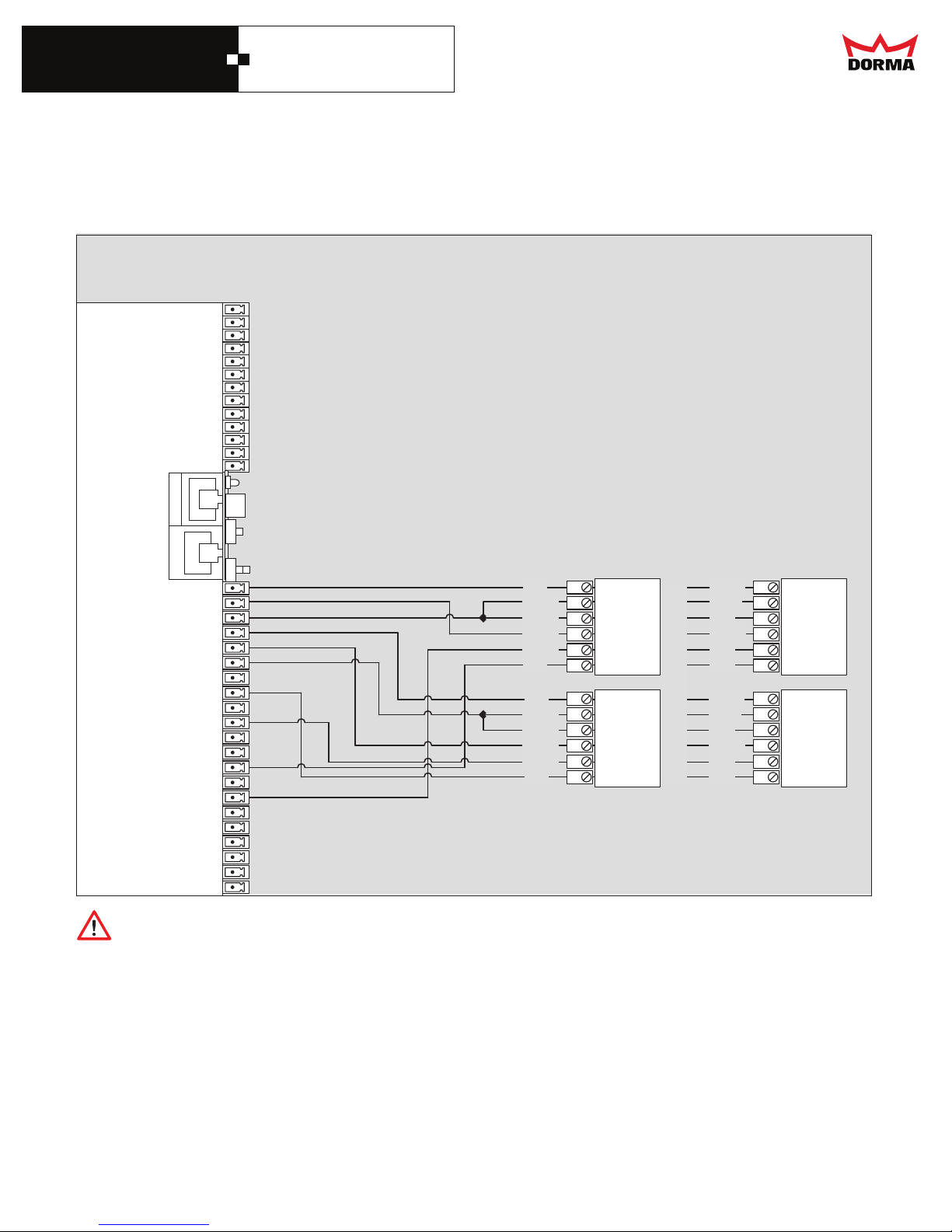
Wiring diagram motion detector / presence sensor (BEA) and (Bircher Reglomat)
14 - 27v +
15 - Radar Outside
16 - Ground
17 - 27v +
18 - Radar Inside
19 - Ground
20 - 27v +
21 - Inside LE2 (NPN)
22 - 27v +
23 - Inside LE2 (GND)
24 - Ground
25 - 27v +
26 - Outside LE1 (NPN)
27 - 27v +
28 - Outside LE1 (GND)
29 - Ground
30
31
32
33
34
1
2
3
4
5
6
7
8
9
10
11
12
13
Control system ESA - II basic module
Red
Black
White
Green
Brown
Blue
Red
Black
White
Green
Brown
Blue
Wizard
Outside
(24v +)
(24v -)
(Common)
(No)
(Common)
(Safety)
(24v +)
(24v -)
(Common)
(No)
(Common)
(Safety)
Wizard
Inside
Bircher Reglomat
Profusion - Outside
Brown
White
Gray
Yellow
Red
Pink
Brown
White
Gray
Yellow
Red
Pink
(24v +)
(24v -)
(Common)
(No)
(Common)
(Safety)
(24v +)
(24v -)
(Common)
(No)
(Common)
(Safety)
Bircher Reglomat
Profusion - Inside
Terminal 21 to 23 and terminal 26 to 28 must have a N.C. circuit.
17
DORMA AUTOMATICS, Inc. 924 Sherwood Drive Toll-Free: 877-367-6211 DL2842-010
Lake Bluff, IL 60044 Fax: 877-423-7999 rev. A
Page 19
DORMA
ESA II Controller
and Wiring Manual
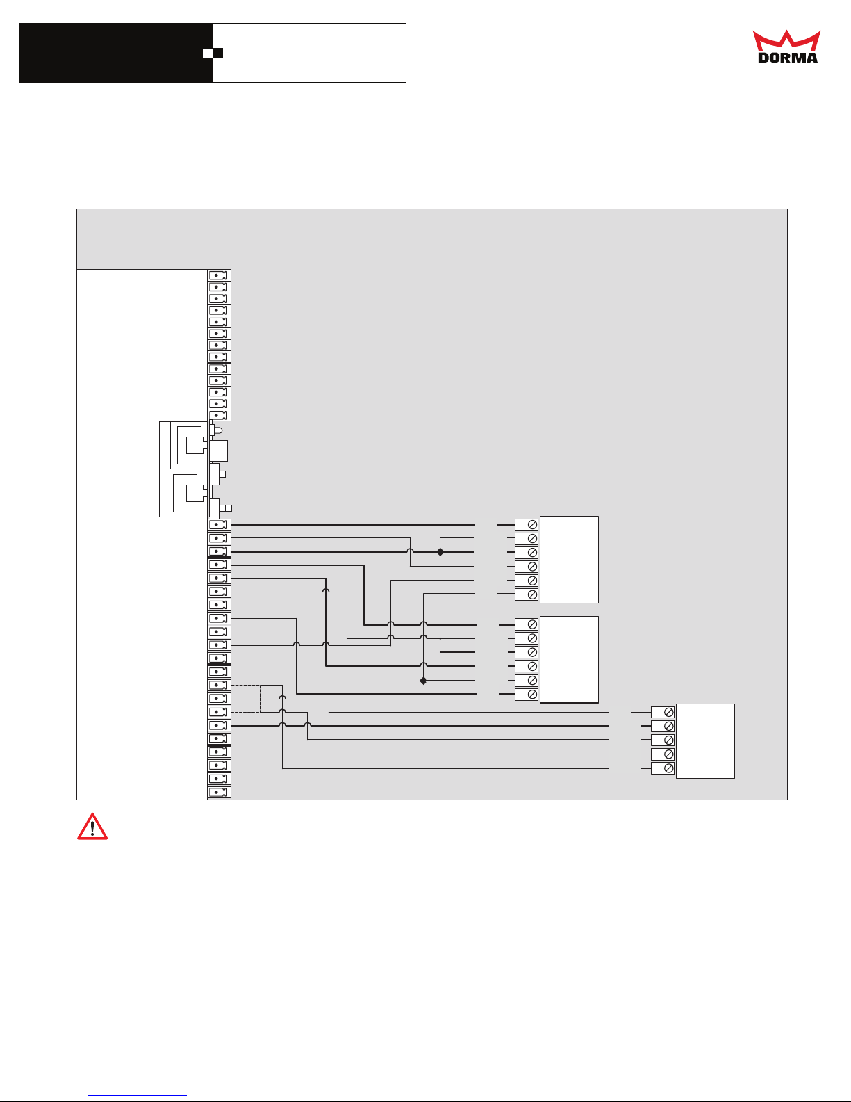
Wiring diagram motion detector / presence sensor (BEA)
14 - 27v +
15 - Radar Outside
16 - Ground
17 - 27v +
18 - Radar Inside
19 - Ground
20 - 27v +
21 - Inside LE2 (NPN)
22 - 27v +
23 - Inside LE2 (GND)
24 - Ground
25 - 27v +
26 - Outside LE1 (NPN)
27 - 27v +
28 - Outside LE1 (GND)
29 - Ground
30
31
32
33
34
1
2
3
4
5
6
7
8
9
10
11
12
13
Control system ESA - II basic module
Red
Black
White
Green
Brown
Blue
Red
Black
White
Green
Brown
Blue
(24v +)
(24v -)
(Common)
(No)
(Common)
(Safety)
(24v +)
(24v -)
(Common)
(No)
(Common)
(Safety)
Wizard
Outside
Wizard
Inside
Red
Black
White
Green
Brown
Optional
(24v +)
(24v -)
(Common)
(No)
(Nc)
BEA
MICRO
CELL
ONE
When beams are not used, jumper terminal 26 and 28.
18
DORMA AUTOMATICS, Inc. 924 Sherwood Drive Toll-Free: 877-367-6211 DL2842-010
Lake Bluff, IL 60044 Fax: 877-423-7999 Rev. A
Page 20
DORMA
ESA II Controller
and Wiring Manual
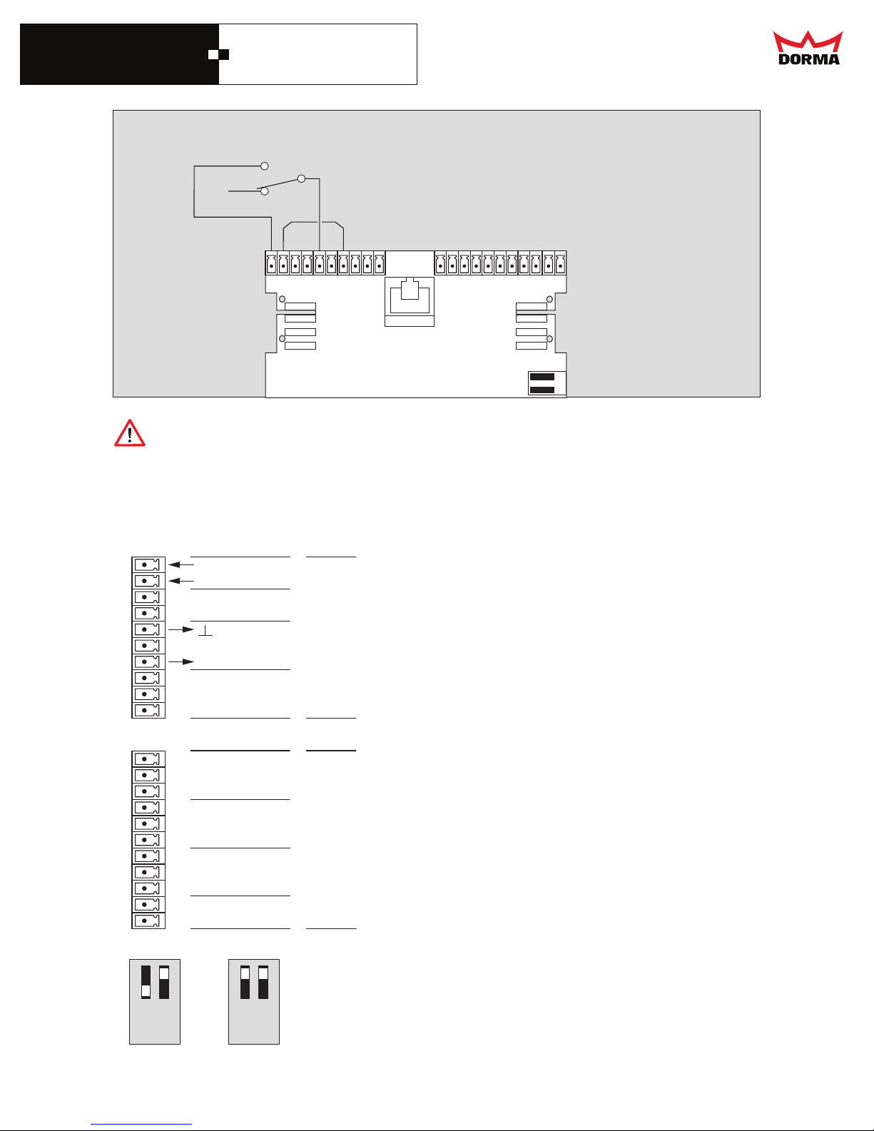
Wiring diagram panic closing function
Panic switch
91
81
12
02
22324252
61
71
51
Does not meet BHMA / ANSI 156.10
This function overrides all safety devices
Door will close if switch is activated
Description and
terminal connections
Control system
Digital input
21
20
19
18
17
16
15
14
13
12
IN IN +
GND
+ 27 V DC
IN 4
IN 3
IN 2
IN 1
Panic closing
Digital output
_
_
ESA - II Function module
41
31
21
11
01
9
8
Function setting via PDA
7
6
5
4
3
2
1
OFF
ON
12 62728292
11
10
9
8
7
6
5
4
3
2
1
DCW Adress 49 oder Adress 48
1 2
ON
19
DORMA AUTOMATICS, Inc. 924 Sherwood Drive Toll-Free: 877-367-6211 DL2842-010
Lake Bluff, IL 60044
E-mail: [email protected] Subject to change without notice
OUT 4
OUT 3
OUT 2
OUT 1
DCW Adress 49 or Adress 48
1 2
ON
Fax: 877-423-7999 rev. A
Page 21
DORMA
ESA II Controller
and Wiring Manual
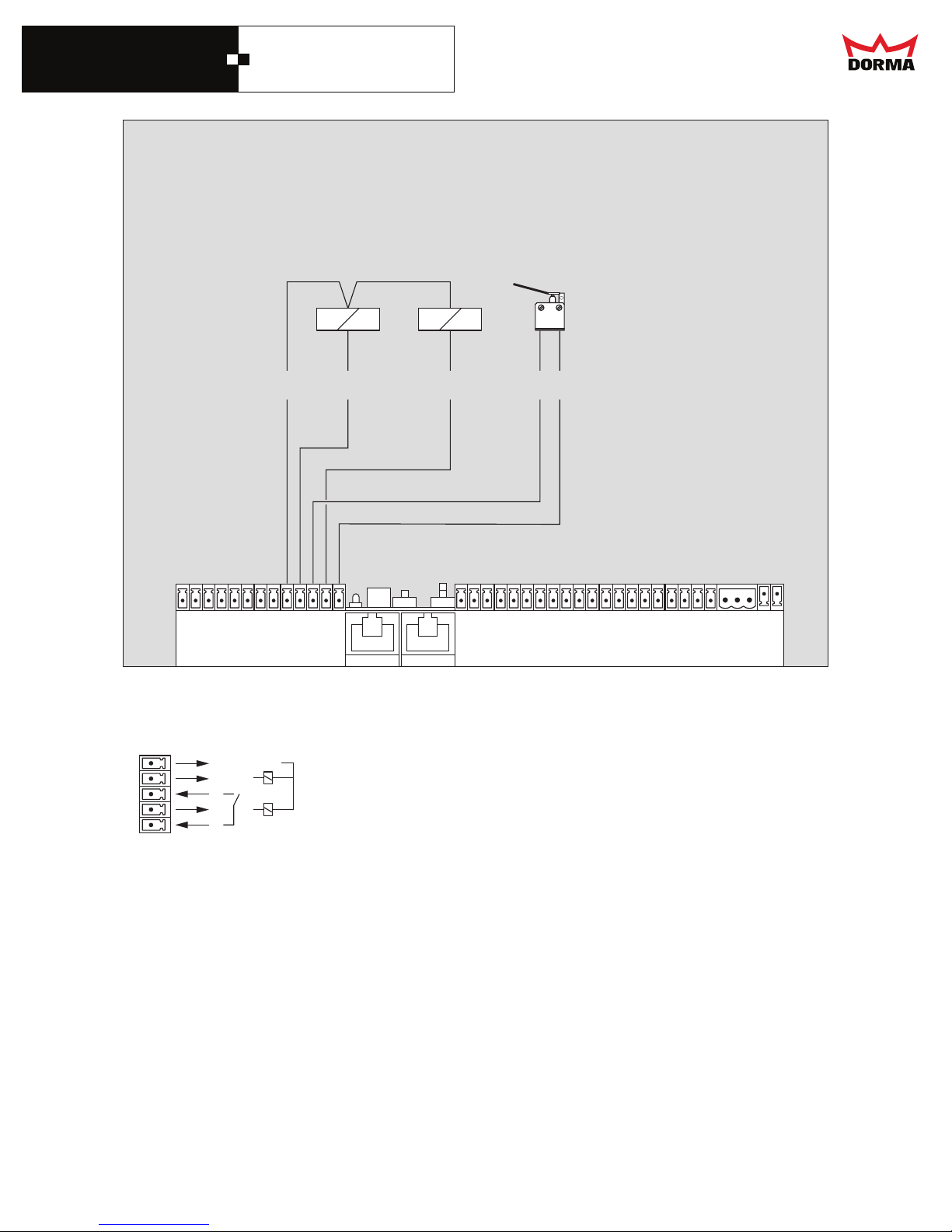
Wiring diagram for electric lock
10
11
12
13
Lock
Feedback
signal contact
HW
NB
GR
Control system ESA - II basic module
1
2
3
4
5
6
7
11
8
9
10
12
13
14
15
16
17
HW
NB
_
_
18
19
20
21
22
23
24
25
26
27
28
29
30
31
32
33
34
35
36
37
38
Description and
terminal connections
Control system
9
+ 27 V DC
Locking
Unlocking
Feedback s i gnal contact
20
DORMA AUTOMATICS, Inc. 924 Sherwood Drive Toll-Free: 877-367-6211 DL2842-010
Lake Bluff, IL 60044 Fax: 877-423-7999
rev. A
Page 22
DORMA
ESA II Controller
and Wiring Manual
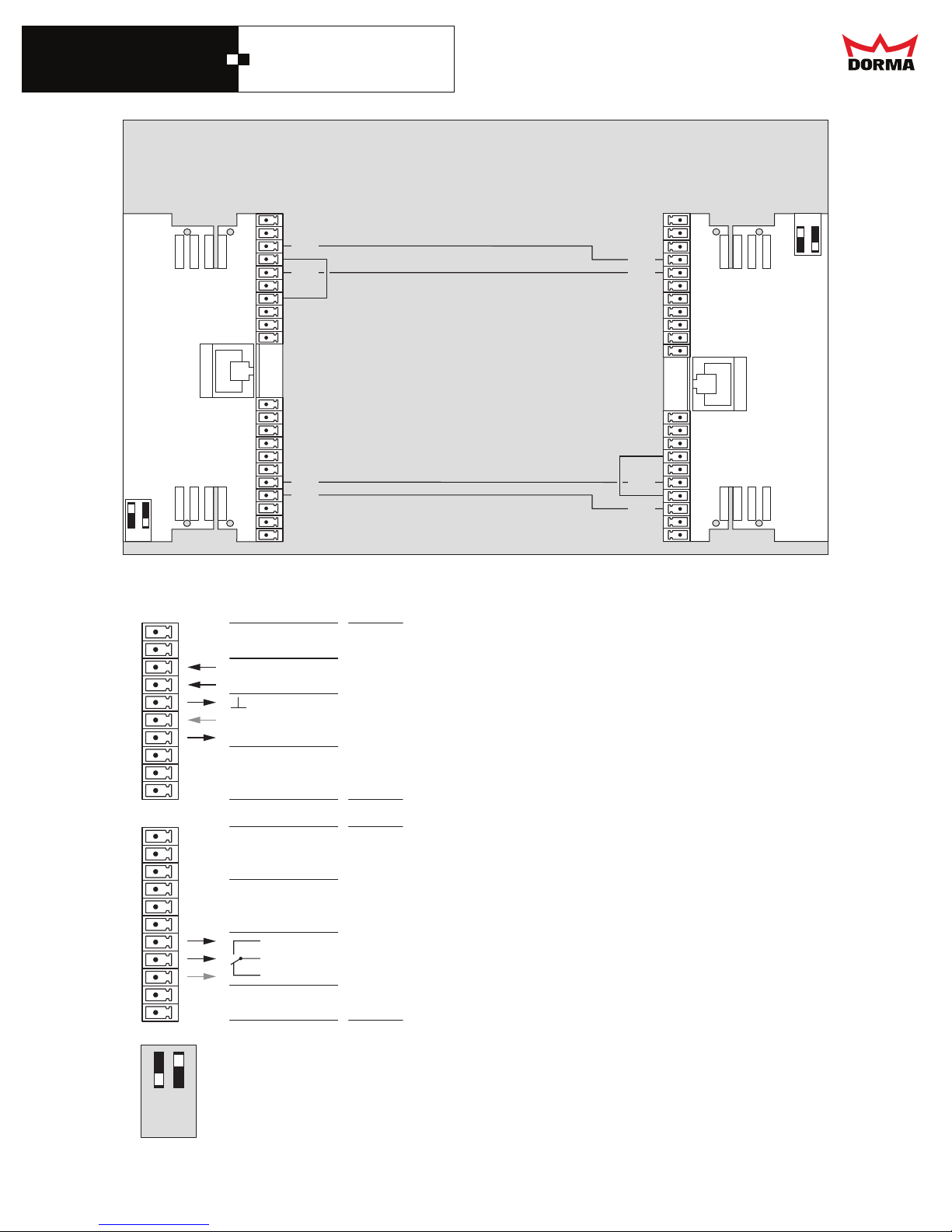
Wiring diagram for airlock
Door A
_
_
ESA - II function module
2524 23 22
OFF
ON
2 1 2928 27 26
21
20
19
18
17
16
15
14
13
12
11
10
9
8
7
6
5
4
3
2
1
DCW Adresse 49
21
20
19
18
17
16
15
14
13
12
11
10
9
8
7
6
5
4
3
2
1
IN IN +
GND
IN -
+ 27 V DC
NO
C
NC
GN
YE
BN
WH
IN 4
IN 3
IN 2
IN 1
OUT 4
OUT 3
OUT 2
OUT 1
Description and terminal connections
Door A and B: Control system
Digital input
Lock disabled
(own door is blocked out)
Digital output
Lock disabled
(other door is blocked out)
No setting at the PDA required
Door B
_
_
ESA - II function module
26 27 28 29 1 2
GN
YE
BN
WH
1
2
3
4
5
6
7
8
9
10
11
12
13
14
15
16
17
18
19
20
21
22 23 24 25
ON
OFF
1 2
ON
21
DORMA AUTOMATICS, Inc. 924 Sherwood Drive Toll-Free: 877-367-6211 DL2842-010
Lake Bluff, IL 60044
E-mail: [email protected] Subject to change without notice
Fax: 877-423-7999 rev. A
Page 23
DORMA
7
ESA II Controller
and Wiring Manual
DORMA
7
ESA II Controller
and Wiring Manual
7
7
4
4
3
4
3
7
3
2
2
2
5
1
1
1
1
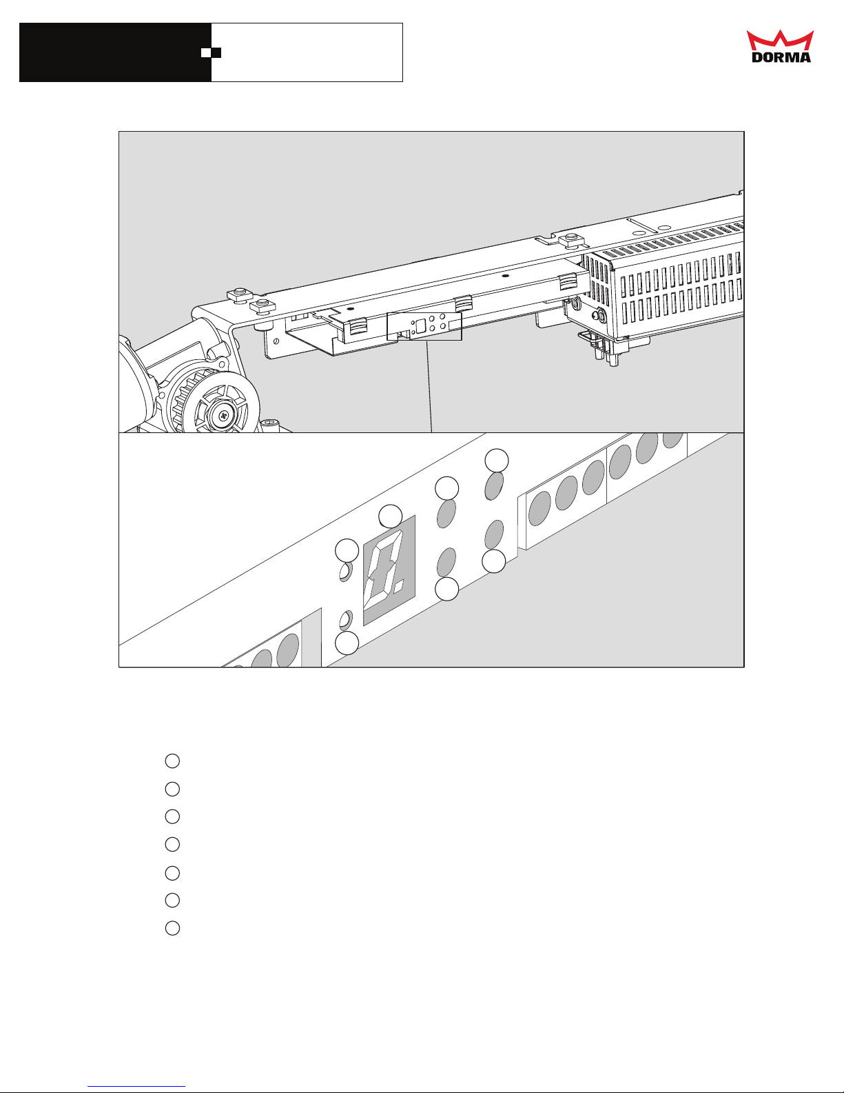
LED 1 Status information of safety sensor 1 (e.g. safety beam)
2
LED 2 Status information of safety sensor 2 (e.g.) safety beam
3
7-segment-display Display unit for indicating numbers and symbols
4
+ UP push button for increasing the parameter or value indicated
6
5
5
6
6
- DOWN push button for decreasing the parameter or value indicated
5
SEL. Push button for MENU control
6
SERV. Push button for performing the functions of the service push button
7
22
DORMA AUTOMATICS, Inc. 924 Sherwood Drive Toll-Free: 877-367-6211 DL2842-010
Lake Bluff, IL 60044
E-mail: [email protected] Subject to change without notice
SELECT
Service
Fax: 877-423-7999 rev. A
Page 24
DORMA
ESA II Controller
and Wiring Manual
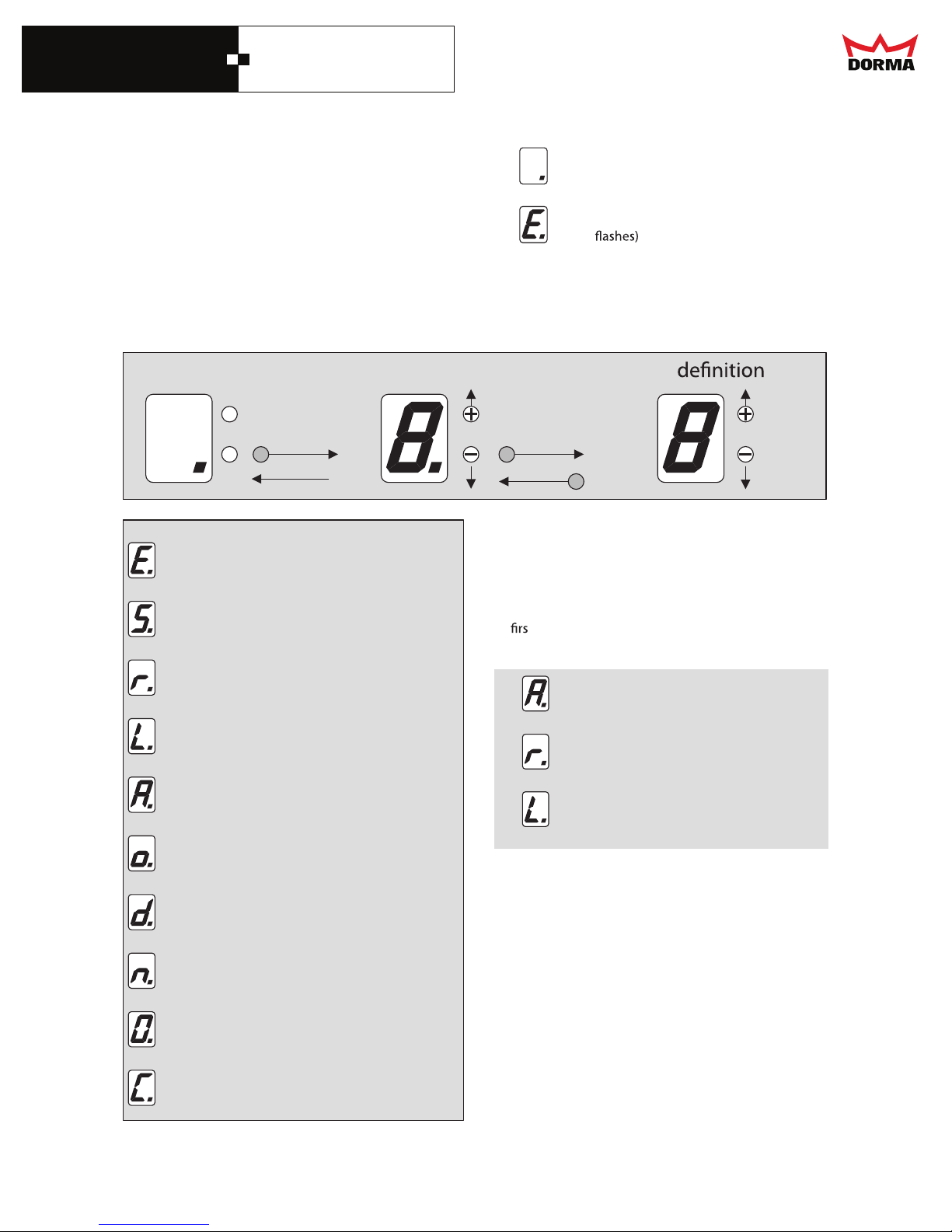
Description of menu structure
Display when in operation
Basic display setting when the operator is functioning correctly
Basic display setting when the operator is malfunctioning (display
Parameter Display
Menu for selecting the parameter to be checked or changed
Value Display
Readout of the value previously selected via the parameter display.
Operation mode
SELECT
automatically
after 20 sec.
Meaning of display codes
Error display
Temper block
Locking in Program switch settings
Locking mode
Back up battery operation
Menu level Parameter
SELECT
SELECT
Display codes
0 - F
Modifying the parameters of the
system using the push buttons
"+", "-", and "select”
0 - 1
0 - 1
0 - 3
0 - 3
At t the following sequense must be observed
when setting the parameters.
1. check and switch if necessary
2. check and switch if necessary
3. check and switch if necessary
Night-bank-hold open time
Hold open time
Side lite function
Opening speed
Closing speed
23
DORMA AUTOMATICS, Inc. 924 Sherwood Drive Toll-Free: 877-367-6211 DL2842-010
Lake Bluff, IL 60044
E-mail: [email protected] Subject to change without notice
0 - 9, F
0 - 9, F
0 - 1
0 - d
0 - 4
Fax: 877-423-7999 rev. A
Page 25
DORMA
ESA II Controller
and Wiring Manual
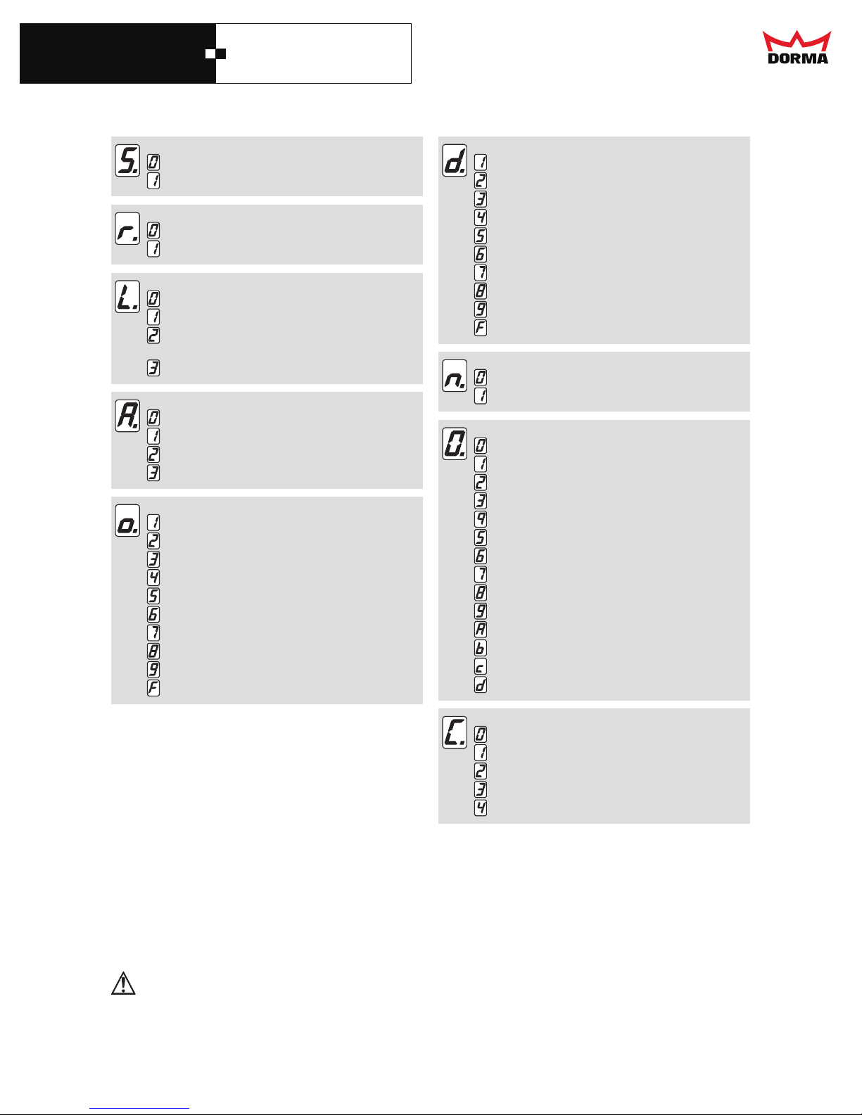
Meaning of display codes
Temper block
Temper block activated
block de-activatedTemper
Locking in program switch setting:
setting “OFF“
setting “OFF“ and “EXIT ONLY”
Interlock type:
No interlock
Bistable interlock
Bistable interlock with
status signalling contact (NO)
Monostable interlock (fail safe)
Battery mode
no Battery
Emergency closing
Emergency opening
Battery Emergency mode
Night-/ Bank Hold open time
1.5 sec
2.5 sec
5 sec
8 sec
10 sec
15 sec
20 sec
25 sec
30 sec
Adjustment via PDA > 30 sec
Hold open time
1.5 sec
2.5 sec
5 sec
8 sec
10 sec
15 sec
20 sec
25 sec
30 sec
Adjustment via PDA > 30 sec
Side lite function
Stop
Closing cycle
Opening speed:
0.4 in./sec
in./sec
0.6
in./sec
0.8
in./sec
1.0
in./sec
1.2
in./sec
1.4
in./sec
1.6
in./sec
1.8
in./sec
2.0
in./sec
2.2
in./sec
2.4
in./sec
2.6
in./sec
2.8
in./sec
3.0
Closing speed
in./sec
0.4
in./sec
0.6
in./sec
0.8
in./sec
1.0
in./sec
1.2
The hold-open time, adjusted via the PDA, is also indicated on the 7-segment display of the control unit.
As the display of the control unit follows a certain pattern (see above), it always indicates the next value below.
For example:
Adjustment of PDA = 14 sec => display of control unit = 5
Adjustment of PDA = 21 sec => display of control unit = 7
This is also the case with the Night-/ Bank hold-open time.
According to BHMA / ANSI 156.10, the Hold-open time and the Night-/Bank Hold-open time
have to be adjusted to at least 2.5 sec. when light barriers are applied.
24
DORMA AUTOMATICS, Inc. 924 Sherwood Drive Toll-Free: 877-367-6211 DL2842-010
Lake Bluff, IL 60044
E-mail: [email protected] Subject to change without notice
Fax: 877-423-7999 rev. A
Page 26
DORMA
ESA II Controller
and Wiring Manual
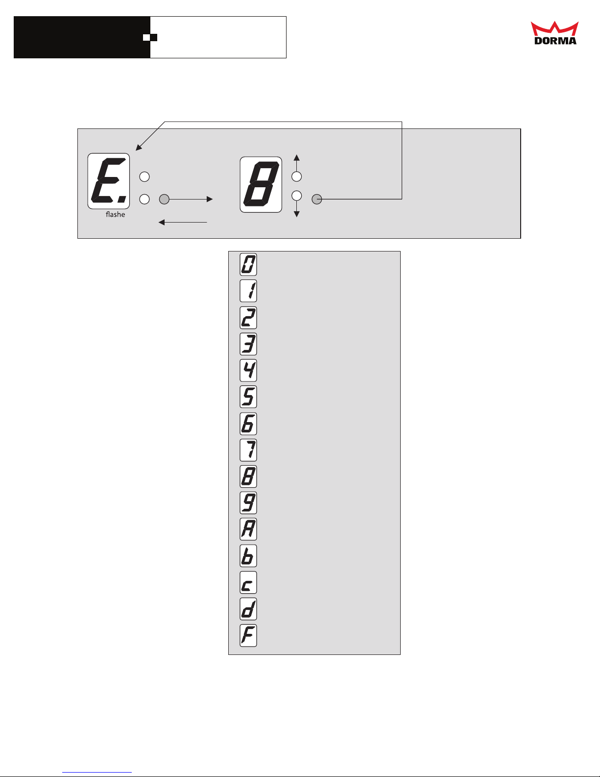
Query of error messages Only the current error can be acknowledged
(The errors must be corrected before resetting)
Up to 10 errors can be stored (regardless of type)
Error last occurring error
Display
+
_
s
Automaticlly
after 10 sec.
The previously occurring error is displayed
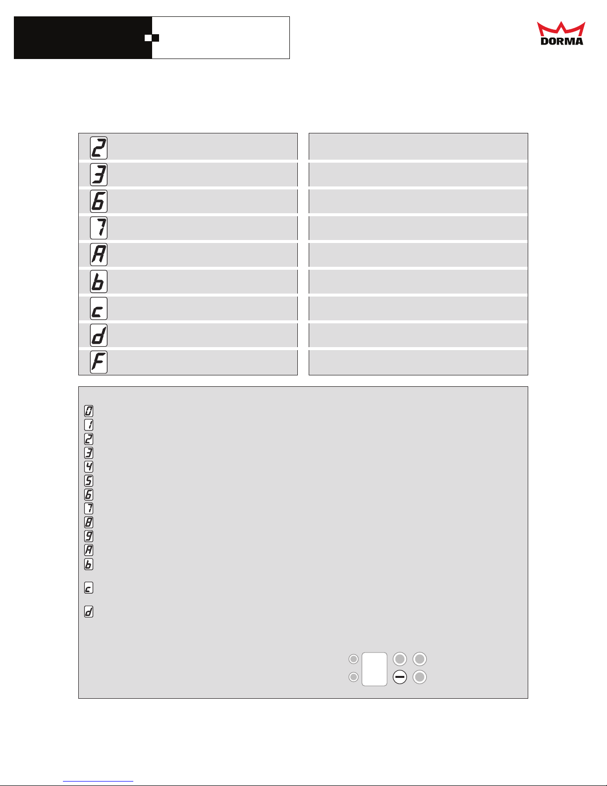
Meaning of display codes
No error in memory
Obstruction
Lock
Program switch
Safety beam
Incremental encoder
Back up battery test error
System
TCELESTCELES
Breakout operated
Learning cycle parameter error
Motor fault
Battery test error
Force test
Overcurrent at motor
DCW
Additional error displays appear in the PDA
25
DORMA AUTOMATICS, Inc. 924 Sherwood Drive Toll-Free: 877-367-6211 DL2842-010
Lake Bluff, IL 60044 Fax: 877-423-7999 rev. A
E-mail: [email protected] Subject to change without notice
Page 27
DORMA
ESA II Controller
and Wiring Manual
Error messages appearing on the PDA are explained in the instruction
PDA software for ESA - II (ASP)
ADPehtybdedrocerebylnonacsrorreesehTsedocyalpsidfogninaeM
32,61,51kcoL
22hctiwsmargorP
82rorretsetyrettabpukcaB
CPU, RAM, ROM, EE-PROM, Relay test 21
01tluafrotoM
11rorretsetyrettaB
21tsetecroF
31tnerrucrevorotoM
92,51WCD
Message Error Method of acknowledgement
No error in memory
egdelwonk-fleSnoitcurtsbO
Turn p
Incremental encoder Turn program switch to CLOSE
Back up battery test error Turn program switch to CLOSE
sniamelcyCtsetsialer,metsyS
EMERGENCY OFF Release EMERGENCY OFF
Learning cycle parameter error Turn program switch to CLOSE
No battery detected on battery test: Turn program switch to CLOSE
Reset performed by contro
Force test "No battery" mode: Turn program switch to CLOSE
Overcurrent at motor longer than 30 sec Turn program switch to CLOSE
Commissioning error
EMERGENCY OPEN mode: wait until force test in open position porduces "OK"
Change direction of motor rotation
During commissioning, door panels open
o CLOSEthctiwsmargorkcoL
o CLOSEthctiwsmargorpnruThctiwsmargorP
o CLOSEthctiwsmargorpnruTSafety beam
egdelwonk-fleStluafrotoM
During the cycle press
26
DORMA AUTOMATICS, Inc. 924 Sherwood Drive Toll-Free: 877-367-6211 DL2842-010
Lake Bluff, IL 60044 Fax: 877-423-7999 rev. A
E-mail: [email protected] Subject to change without notice
Page 28
DORMA
ESA II Controller
and Wiring Manual
1
2
LED
3
Start
Status
Service
Key
Infrared
4
5
Description and
terminal connections
RJ45
1
LED
2
3
4
SUB D
5
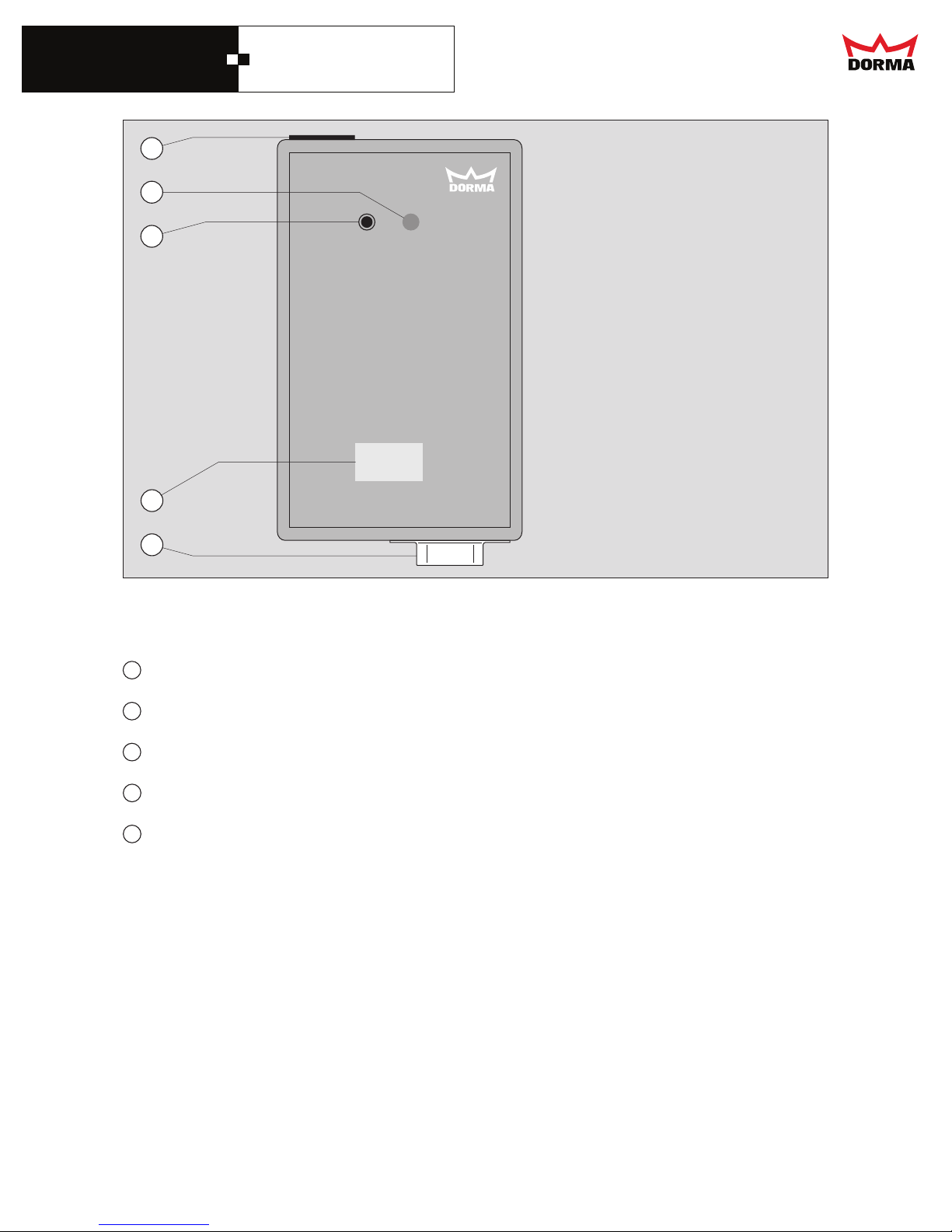
Connecting port for control unit
LED status indicator
Start push button
Infrared device
Connecting port for PDA
27
DORMA AUTOMATICS, Inc. 924 Sherwood Drive Toll-Free: 877-367-6211 DL2842-010
Lake Bluff, IL 60044 Fax: 877-423-7999 rev. A
E-mail: [email protected] Subject to change without notice
Page 29
DORMA
ESA II Controller
and Wiring Manual
ESA - II Service-Key
The service key is the linking element between the PDA (Personal Digital Assistant) and the control
unit. It may also be used with the control unit without PDA in order to disable the control keys of the control unit or
to update the software of the control unit.
Operation via PDA
The PDA is connected to the service key (9-pole SUB D plug) with a serial connecting cable. Connect the service
key via the connecting cable to the control unit (Port 13 behind the service keys). Establish a connection between
the controller and the PDA (see ASP operating instructions). The LED status indicator on the service key turns
green. Now the settings may be changed via the PDA. An upload must be performed in case that any settings
have been changed. The LED status indicator of the service key lights red, in the event, that an error occurs during
upload. In this case the upload must be repeated. If the upload was successful, the LED is green. The PDA may
also be used to install a new software version on the service key. Software upload from PDA to service key: See
"ESA" ASP data base recording.
Software update of
The service key must contain the latest software version.
The software update may not be done while the door is under operation, as it could get out of
control.
Take the sliding door out of operation (set Program switch to CLOSE, or use the EMERGENCY OFF
push buttonif necessary.) Press and hold the start push button for three seconds. The LED status indicator on the
service key
upload. In this case, the upload must be repeated. If the upload was successful, the LED turns green.
Locking the control panel via service key.
If the control panel of the control system is locked, the service key unlocks it, by connecting it.
The settings can now be changed. As soon as the service key is disconnected from the control unit, the control
panel is locked automatically.
LED status indicator
Troubleshooting
The control unit indicates an error code in the event of an incomplete update.
The LED status indicator on the service key goes out.
Should one of the above-mentioned errors occur, the system must be disconnected from power supply and the ES 200 control
unit has to be programmed again.
ESA - II
Following a software update, the power supply must be reset (battery pack and power plug must be
removed for a short time) and a learning cycle has to be performed. The door settings must be
checked and reset if required (e.g. locking type, motor type, operation via battery pack etc.).
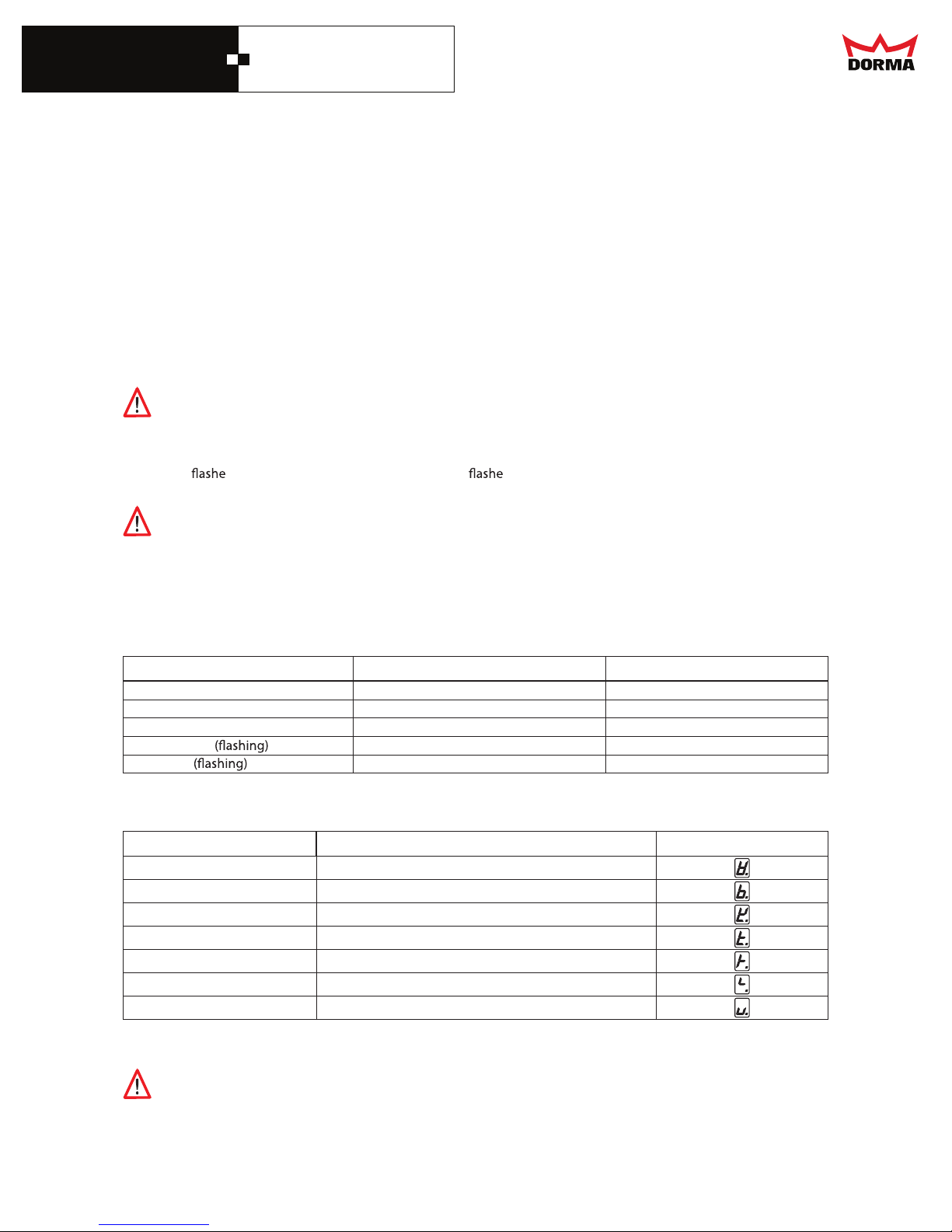
LED status indicator Update PDA service key Update SK control unit
Orange
Red
Bootloader CRASH ROM checksum error
ESA-II control unit via service key
s orange while it performs the update. It s red in the event that an error occurs during
ESA - II
ssergorpnietadpUegnarO
etadpugnirudrorrEdeR
metsyS10
ecneuqesmargorP30
rorreMAR50
denifedtonrotceVtpurretnI70
kcehc-MAR51
ESA - II
lufsseccusetadpUlufsseccusetadpUneerG
Update in progress
Error during update
yalpsidrorrEsnosaerelbissoPedocrorrE
)gnimiT-WCD(ecneuqesreldnaHkcolC-SOMD13
The system cannot be updated via infrared device.
28
DORMA AUTOMATICS, Inc. 924 Sherwood Drive Toll-Free: 877-367-6211 DL2842-010
Lake Bluff, IL 60044 Fax: 877-423-7999 rev. A
E-mail: [email protected] Subject to change without notice
 Loading...