

Page 1
Instructions
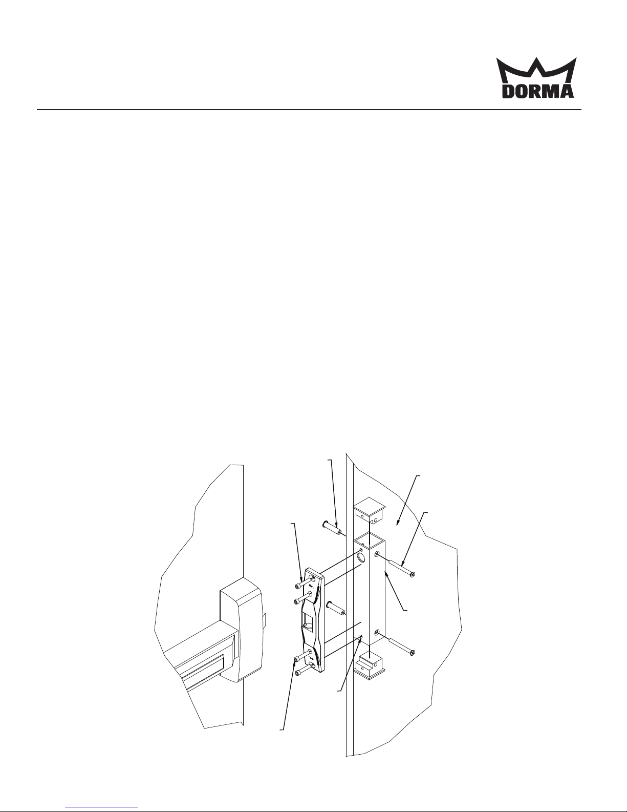
1. Mark horizontal center line (CL) of existing device latch from active door to inactive door.
2. Mark the mounting holes for the Door Pair Housing (DPH) on the inactive door.
3. Drill two 13/32” (10.5mm) holes through inactive door.
4. Mount DPH to inactive door using hardware as shown below.
Note: Wire access hole is not provided, drill DPH as required.
5. Make wire connections from the power source to the appropriate wire harness supplied. Use the 12V
harness for 12VDC, 12-24VAC or 11-16VAC. Use the 24V harness only for 24VDC.
6. Mount the electric strike with 1/4-20 UNC (Hole C) screws provided in the horizontal mounting holes (the
outer slots). Adjust electric strike horizontally until exit device latch fully engages with the door closed.
Note: Ensure a 1/16” [1.5mm] clearance between exit device latch and the electric strike is maintained.
7. Tighten the two mounting screws and check operation. Adjust the horizontal position of electric strike as
required.
8. Using the electric strike as a template, drill & tap for 1/4-20 UNC (Hole D) screws the two locking holes.
Using the 1/4-20 UNC screws provided secure the electric strike through the locking holes.
Note: ES 62 strike is not adjustable after installing these screws.
ISES62DPH
08281190
PCN110055
R11/11SH
Typical Door Pair
Housing Assembly
INACTIVE
DOOR
SEX NUT 1/4-20
WITH 13/32" HOLE
THROUGH (DOOR)
(2 PLACES)
1/4-20 X 2.5"
(2 PLACES)
ES62 DPH
HOLE C
1/4-20 X 1"
SCREW
HOLE C
1/4-20 X 1"
SCREW
HOLE D
1/4-20 X 1"
SCREW
(2 PLACES)
Electric Strikes
INSTALLATION
ES62 - DOOR PAIR HOUSING
© 2011 DORMA
USA: DORMA DRIVE, DRAWER AC, REAMSTOWN, PA 17567 PHONE: (800) 523-8483 (717) 336-3881 FAX: (717) 336-2106
EMAIL: [email protected] WEBSITE: dorma-usa.com
Page 2
ES62 Door Pair Housing Installation Instructions (con’t)
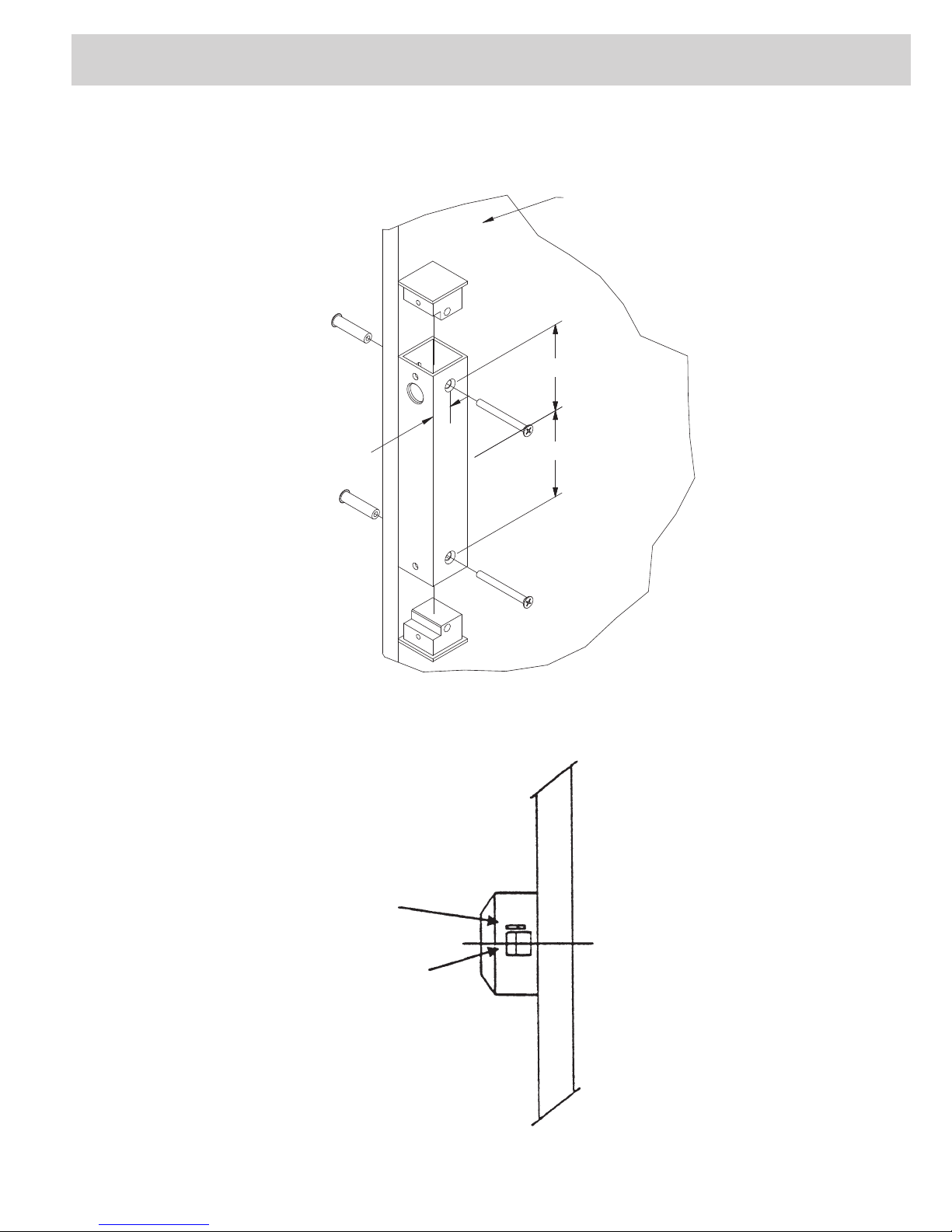
Door Prep Details
INACTIVE
DOOR
3-
3/4" (95.0mm)
3-3/4" (95.0mm)
7/8" (22.2mm)
C
L
NOTE: Not to scale. Specifications are subject to change without notice.
Typical Surface Exit Device
ACTIVE DOOR
EDGE
DEADLOCKING
TRIGGER
LATCH
C
L
© 2011 DORMA
USA: DORMA DRIVE, DRAWER AC, REAMSTOWN, PA 17567 PHONE: (800) 523-8483 (717) 336-3881 FAX: (717) 336-2106
EMAIL: [email protected] WEBSITE: dorma-usa.com
 Loading...