

Page 1

DORMA
1
WN 057065 45532
11/06
01
ES 200 T
ES 200 T
ES 200 T-2D
D
GB
F
Easy
ES 200 T ES 200 T ES 200 T-2DEASY
DK
S
N
FIN
E PINL
PL
m=2x50kg
LW: 800 - 2400 mm
m=4x43kg
LW: 1400 - 4000 mm
ES 200 T
ES 200 T
ES 200 T
ES 200 T
ES 200 T
ES 200 T
m=2x75kg m=2x75kg
LW: 800 - 2400 mm LW: 1000 - 2400 mm
m=4x75kg m=4x65kg
LW: 1400 - 4000 mm LW: 1400 - 4000 mm
EasyEasy
-2D-2D
MontageanleitungMontageanleitung Fixing instructionsFixing instructions
255 336-01-6-50
01
Page 2

DORMA
2
Inhaltsverzeichnis 255 336-01-6-50 ..................................... 03.2008
02 03/08
Inhaltsverzeichnis ......................................................................................................................................................... 2
Contents .............................................................................................................................................................. 3
WN 057065 45532
Wichtige Hnweise vor der Montage ................................................................................................................................ 4
Montageanleitung
ES 200 T
Easy
ES 200 T
ES 200 T-2D
........................................................................................................................................................ Seite
Bilder
- Übersicht, erläuterung der Symbole, allgemeine Hinweise .................................................................... 5
- Auflistung der benötigte Profile ........................................................................................................... 6
- Vorbereitung Antriebsprofil / entfernen von diverse Komponenten ........................................................ 7
- Vorbereitung Wandmontage ................................................................................................................. 8
- Vorbereitung Durchgangmontage ......................................................................................................... 9
- Montage der Seitenteile und der Bodengleiter.................................................................................... 10
- Laufwagen langsame Fahrflügel montieren und Fixierung Mitnahmeseil.............................................. 11
- Montage der Lichtschrankenkabel ..................................................................................................... 12
- Montage der Kabelkanäle und Langsame Fahrflügel einsetzen ........................................................... 13
- Langsame Fahrflügel justieren und Entgleisungsschutz einstellen ...................................................... 14
- Laufprofil wiedereinsetzen, Lichtschranke, und der Lichtschrankenprofile einsetzen .......................... 15
- Laufwagen schnelle Fahrflügel montieren........................................................................................... 16
- Schnelle Fahrflügel montieren ........................................................................................................... 17
- Schnelle Fahrflügel justieren und Entgleisungsschutz einstellen ........................................................ 18
- Endanschläge und Öffnungsweite justieren ................................................................................ 19 - 20
- Einbau der Mini-Drive-Unit und der Umlenkung (Verriegelung) ........................................................... 21
- Einbau von Zahnriemen, Halterung der Innenverkleidung und Optionen .............................................. 22
- Schließkante justieren ....................................................................................................................... 23
- Zahnriemenspannung einstellen ......................................................................................................... 2 4
- Verriegelung (Option) einstellen ......................................................................................................... 25
- Zahnriemen einstellen ........................................................................................................................ 26
- Stirnbleche und Innenverkleidung vorbereiten , Stirnbleche montieren .............................................. 26
- Innenverkleidung einsetzen und erden ............................................................................................... 27
- Testbetrieb ........................................................................................................................................ 28
Montageanleitung
Text Deutsch ............................................................................................................................................ 29 - 32
Text Englisch ........................................................................................................................................... 33 - 36
Technische Daten................................................................................................................................................ 37 - 38
Sicherheitshinweise DIN 18650 .......................................................................................................................... 39 - 40
Änderungen vorbehalten
2
DORMA GmbH + Co.KG Postfach 40 09 D-58247 Ennepetal • Breckerfelder Straße 42-48 D-58256 Ennepetal
Automatic Division Tel. +49 (0) 23 33 / 793-0 • Fax +49 (0) 23 33 / 79 34 95 • www.dorma.com
Page 3

DORMA
3
Contents 255 336-01-6-50 .................................................. 03.2008
03 03/08
Contents German .......................................................................................................................................................... 2
Contents .............................................................................................................................................................. 3
WN 057065 45532
Before fixing .............................................................................................................................................................. 4
Fixing Instructions
ES 200 T
Easy
ES 200 T
ES 200 T-2D
......................................................................................................................................................... Page
Drawings
- Overview, explanation of symbols, general informations ........................................................................ 5
- List of the profiles ................................................................................................................................6
- Preparation of operator profile / taking off some components .............................................................. 7
- Preparation for wall fixing .................................................................................................................... 8
- Preparation for corridor fixing .............................................................................................................. 9
- Installation of side screen (corridor fixing) and floor guide................................................................. 10
- Installation of the slow sliding panels and the connecting cord .......................................................... 11
- Installation of light barrier cable ........................................................................................................ 12
- Installation of cable trunking and slow sliding panels ......................................................................... 13
- Adjustment of slow sliding panels and derailment guard ..................................................................... 1 4
- Installation of track rail for the fast carrier unit, installing of light barrier and their profiles .............. 15
- Installation of fast carrier unit ........................................................................................................... 16
- Installation of fast sliding panels ....................................................................................................... 17
- Adjustment of fast sliding panels and derailment guard ...................................................................... 18
- Adjustment of end stops and opening width ................................................................................ 19 - 20
- Installation of the Mini-Drive-Unit and pulley / locking device ............................................................ 21
- Installation of toothed belt, cover holder and accessories .................................................................. 22
- Adjustment of closing edge ................................................................................................................ 23
- Tensing the toothed belt .................................................................................................................... 24
- Adjustment of locking device (optional) ............................................................................................. 25
- Adjustment of toothed belt ................................................................................................................. 26
- Preparation of end plates and inner cover, Fix end plates ................................................................... 26
- Installation, fitting and ground of inner cover ..................................................................................... 27
- Connecting and testing the system ..................................................................................................... 28
Fixing instruction
Tehnical data .................................................................................................................................................... 37 - 38
Safety advice DIN 18650 .................................................................................................................................... 41 - 42
text German ........................................................................................................................................... 29 - 32
text English ............................................................................................................................................ 33 - 36
Subject to change without notice
DORMA GmbH + Co.KG Postfach 40 09 D-58247 Ennepetal • Breckerfelder Straße 42-48 D-58256 Ennepetal
Automatic Division Tel. +49 (0) 23 33 / 793-0 • Fax +49 (0) 23 33 / 79 34 95 • www.dorma.com
3
Page 4

DORMA
4
ES 200 T
Easy
ES 200 T
ES 200 T-2D
02 03/08
WN 057065 45532
Montageanleitung
in Bild und Text.
Bild und Text mit der gleichen
Bezeichnung zum Beispiel
gehören zusammen.
1A
1A
Bild und Text mit der Bezeichnung
1A
1B
1B
1a
2A 3A
2B1b3B
1c
z. B.: 1A
gehören zur Wandmontage.
Bild und Text mit der Bezeichnung
z. B.:
gehören zur Durchgangsmontage.
Bild und Text mit der Bezeichnung
z. B.:
sind Montagevarianten.
Wichtige Hinweise vor der Montage
Wichtig!
Diese Dokumentation ist gültig für die
elektrischen Schiebetürantriebe
ES 200 T, ES 200 T
Abweichungen in der bildlichen Darstellung zum
realen Antrieb sind unerheblich und haben auf
die Montage keinen Einfluss.
Da wo Unterschiede bei der Montage oder in den
Funktionen auftreten werden die Unterschiede
benannt und hervorgehoben.
Zum Beispiel durch einen Hinweis:
- nur bei ES 200 T,
- nur bei ES 200 T
- nur bei ES 200 T-2D oder ähnlich.
Easy
, ES 200 T-2D.
Easy
,
Wichtig!
Bei ES 200 T-2D Anlagen muss eine Verriegelung
mit Rückmeldekontakt eingesetzt werden.
Fixing instructions
including drawings and descriptive texts.
Drawings and texts with the same
designation i.e.
1A
1A
belong together.
Drawing and text with designation
1A
1B
1a
2A 3A
2B1b3B
1c
e.g.
belong to wall fixing
Drawing and text with designation
e.g.
belong to corridor fixing
Drawing and text with designation
e.g.
are fixing variants
Before fixing:
Important!
This documentation is applicable for the
following electro-mechanical sliding door
operators:
ES 200 T, ES 200 T
Discrepancies between the drawings and the
actual drive unit are irrelevant and do not effect
the fixing.
Differences in function and fixing between the
drive units are mentioned and indicated by the
following instructions or in a similar way:
- only for ES 200 T
- only for ES 200 T
- only for ES 200 T-2D
Easy
, ES 200 T-2D.
Easy
Important!
ES 200 T-2D systems require a locking device
with feedback contact.
Subject to change without notice
Änderungen vorbehalten
4
DORMA GmbH + Co.KG Postfach 40 09 D-58247 Ennepetal • Breckerfelder Straße 42-48 D-58256 Ennepetal
Automatic Division Tel. +49 (0) 23 33 / 793-0 • Fax +49 (0) 23 33 / 79 34 95 • www.dorma.com
Page 5

DORMA
SK
SK
5
WN 057066 45532
12/06
01
100
LH
ES 200 T
ES 200 T
ES 200 T-2D
Easy
SK
150
LH
D
messen
sägen to saw
GB
to measure
m
m
m
m
SK
m
entgraten to deburr
Bohren to bore
senken to lower
schrauben to screw
Gewinde
schneiden
dübeln to peg
Arbeiten an Elektroanlagen dürfen nur von geschulten Fachkräften ausgeführt werden.
Vor dem Einbau vor Ort: Bitte elektrische Anschlüsse prüfen.
Ist die Anlage noch nicht an die bauseitige Stromversorgung angeschlossen:
Akku nur zum Testbetrieb anschließen.
Bei Außerbetriebnahme Akkuanschluß von der Steuerung abziehen.
Work on electrical equipment may only be performed by properly qualified electricians.
Before the installation locally: electrical links please.
If there is no main power: c
By shutdown disconnect the battery from the control system
to hreadscut t
onnect the accumulator only to test
Page 6

DORMA
6
ES 200 T
Easy
ES 200 T
ES 200 T-2D
12/06
02
WN 057066 45532
1
2a 2b
10 9a
1 Montageprofil
2a Antriebsprofil
2b Laufprofil schneller Laufwagen
3 Kabelkanal U-Form
4 Scharnierprofil
5a Innenverkleidung 100 mm
5b Innenverkleidung 150 mm
6 Laufschiene mit Dämmlage
7 Abdeckprofil für LS-Kabel
8 Abdeckprofil Durchgangsbereich
9a Stirnplatte 100 mm
9b Stirnplatte 150 mm
10 Blendeprofil
11 Winkelblendeprofil Durchgangsbereich
7
3
6
4
1
4
5a
2a
2b
11
9b
1 Mounting profile
2a Operator profile
2b Rail
3 U-section cable trunking
4 Hinge profile
5a Internal cover 100 mm
5b Internal cover 150 mm
6 Rail track profile
7 Cable trunking for rail track cable
8 Cover profile for through passage area
9a End plate 100 mm
9b End plate 150 mm
10 Cover profile
11 Angle cover profile for through passage area
profile faster roller carier
8
with rubber strip
7
5b3
6
1A
12a
13
4
2a 2b
10
9a
7
1 Montageprofil nur
2a Antriebsprofil langsame
2b Antriebsprofil schneller Laufwagen
3 Kabelkanal U-Form
14 14
4 Scharnierprofil
5a Innenverkleidung 100 mm
5b Innenverkleidung 150 mm
6 Laufschiene mit Dämmlage
7
8
9a Stirnplatte 100 mm
9b Stirnplatte 150 mm
10 Blendeprofil
11 nur
12a LM-Träger 100 mm
12b LM-Träger 150 mm
13 Abdeckung
14 U-Profil
3
5a6
4A
Abdeckprofil für LS-Kabel
Sichtblende
Winkelblendeprofil
r Laufwagen
4A
1 Mounting profile only
2a Operator profile for slowly carrige
2b
3 U-section cable trunking
4 Hinge profile
5a Internal cover 100 mm
5b Internal cover 150 mm
6 Rail track profile
7
8 Cable trunking for rail track cable
9a End plate 100 mm
9b End plate 150 mm
10 Cover profile
11 Angle cover profile only
12a Aluminium girder 100 mm
12b Aluminium girder 150 mm
13 Cover
14 Channel section
12b
13
Operator profile for rapid carrige
cover plate
2a
2b
9b
with rubber strip
4A
4A
4
6
7810
5b3
1B
Page 7
DORMA
7
WN 057066 45532
12/06
03
2
ES 200 T
ES 200 T
ES 200 T-2D
Easy
2.
1.
3.
1.
2.
3
1.
4
2.
2.
1.
5
Page 8

DORMA
g
g
8
ES 200 T
ES 200 T
ES 200 T-2D
Easy
12/06
04
WN 057066 45532
6A
2.
1.
50 200 200 200 200 200200
43 mm
10 mm
LS-Kabel
LW
LS-Kabel
10 mmLW
43 mm
7A
X=LW/2-5
X=LW/2-10
1.
2.
X=LW/2-5
X=LW/2-10
M6x10
1.
Länge = X
8A
LH
Len
2.
th=X
M6x10
DIN EN ISO 10642
M6x8
DIN EN ISO 10642
DIN EN ISO 10642
M6x8
DIN EN ISO 10642
LH
50
Länge = X
Len
th=X
Page 9

X
X
DORMA
9
ES 200 T
Easy
ES 200 T
ES 200 T-2D
12/06
05
WN 057066 45532
6B
7B
12mm
min 50
42
LH+28
LH+78
140
(LM = 100)
(LM = 150)
140
78
78
(LM = 100) LH + 28
(LM = 150) LH + 78
min 50
42
8B
9B
10B
2.
M6x16
DIN EN ISO 10642
max. 10 mm max. 10 mm
1.
3.
3.
1.
6.
5.
M6x20
DIN ENISO 10642
X
X = min. 40
4.
LH
6.
M6x20
DIN ENISO 10642
M6x16
DIN EN ISO 10642
X
X = min. 40
2.
Page 10

OKF
OKF
DORMA
60
3 x (SPAX 3 x 35)
10
ES 200 T
Easy
ES 200 T
ES 200 T-2D
12/06
06
WN 057066 45532
11B
12B
100mm
220
4xnmm
100mm
150mm
270
100mm
OKF
100mm
100mm
1. 1.
2. 2.
4xnmm
OKF
100mm
100mm
13a
10 x (M4 x 10)
3 x (SPAX3x35)
50
100
60
LW/2 -33
X
X
Fahrflügel LL
Sliding panel LL
13b
min. 45
min. 120
Page 11

DORMA
11
WN 057066 45532
12/06
07
ES 200 T
Easy
ES 200 T
ES 200 T-2D
14c
14b14a
SK
15
2C + 390 mm
2C + 290 mm
2C + 390 mm
2C + 290 mm
Page 12

DORMA
12
WN 057066 45532
12/0608
ES 200 T
ES 200 T
ES 200 T-2D
Easy
16A
18A
16B
17B
18B
16B
17B
18B
19A
19B
19B
Page 13

DORMA
13
WN 057066 45532
12/0609
ES 200 T
Easy
ES 200 T
ES 200 T-2D
20A
21A
20B
21B
20B
21B
22b22a
22c
Page 14

Xmm
Xmm
X = 8,5 mm
X=6mm
OFF
DORMA
14
12/0610
ES 200 T
ES 200 T
ES 200 T-2D
Easy
2.
WN 057066 45532
23
1.
3.
24
25
0,5 mm
2.
0,5 mm
1.
3.
Page 15

DORMA
15
WN 057066 45532
ES 200 T
Easy
ES 200 T
ES 200 T-2D
12/0611
26A 26B 26B
Hauptschließkante
Main closing edge
Hauptschließkante
Main closing edge
27A 27B 27B
SK
Hauptschließkante
Main closing edge
SKSK
28A 28B 28B
Page 16

DORMA
16
WN 057066 45532
ES 200 T
Easy
ES 200 T
ES 200 T-2D
12/06
12
29a 30a
29b 30b
29c 30c
Page 17

DORMA
17
WN 057066 45532
12/0613
31a
ES 200 T
Easy
ES 200 T
ES 200 T-2D
31b
31c
Page 18

DORMA
0,5 mm
2.
2.
3.
1.
3.
1.
2.
0,5 mm
3.
1.
0,5 mm
Xmm
Xmm
X = 8,5 mm
X=6mm
OFF
18
ES 200 T
ES 200 T
ES 200 T-2D
Easy
12/0614
WN 057066 45532
32
2.
1.
3.
33
34
Page 19
4.
1.
3.
4.
1.
3.
4.
1.
3.
1.
4.
3.
"0"
2.
"0"
2.
DORMA
19
WN 057066 45532
12/0615
ES 200 T
Easy
ES 200 T
ES 200 T-2D
35a 35b
36ab
2.
1.
3.
2.
19c
37ab
3.1.
Page 20

1.
DORMA
20
WN 057066 45532
12/0616
ES 200 T
ES 200 T
ES 200 T-2D
3.
3.
Easy
35c
4.
4.
1.
1.
4.
3.
3.
4.
1.
"0"
2.
"0"
2.
36c
19c
37c
1.
3.
2.
3.1.
2.
Page 21

DORMA
-
+
Select
21
WN 057066 45532
12/06
17
ES 200 T
Easy
ES 200 T
ES 200 T-2D
38a
38b
38c
39b39a
39d39c
Page 22

43
-
+
Select
43
43
-
+
Select
43
41
42
43
43
43
41
43
DORMA
22
ES 200 T
Easy
ES 200 T
ES 200 T-2D
AL < 4000 mm = 2 x
12/06
18
AL > 4000 mm = 2 x
WN 057066 45532
40
2x
43
43
43
41
43 43
42
44
Page 23

100 mm
100 mm
2.
3.
1.
2.
3.
1.
DORMA
23
WN 057066 45532
12/0619
ES 200 T
Easy
ES 200 T
ES 200 T-2D
45
AM
SK
2.
2.
AM
46b46a
SK
3.
1.
46c
3.
1.
SK
AM
SK
AM
Page 24

1.
2.
DORMA
24
ES 200 T
Easy
ES 200 T
ES 200 T-2D
12/0620
WN 057066 45532
47a
1.
2.
48a
1.
2.
33 mm
49a 50a
47b
1.
2.
0mm
48b
0mm
Page 25

DORMA
25
WN 057066 45532
12/0621
51
ES 200 T
Easy
ES 200 T
ES 200 T-2D
52
53
min. 1mm
54a 54b
min. 1mm
55
Page 26

DORMA
1.
3.
4.
a
a
2.
2
1010
2
10
26
WN 057066 45532
12/0622
56
ES 200 T
Easy
ES 200 T
ES 200 T-2D
57
Xmm
Xmm
58A 58B
Xmm
Xmm
59
Page 27

DORMA
27
WN 057066 45532
12/06
23
60
ES 200 T
Easy
ES 200 T
ES 200 T-2D
61
62
63
c
a
b
b
64
a
c
Page 28

d
M
DORMA
28
ES 200 T Easy
12/0624
ES 200 T
Easy
ES 200 T
ES 200 T-2D
WN 057066 45532
StandardDisplay
Closingspeed
Openingspeed
Standardised
operation
Numberof
doorpanels
Motortype
65a
side
eroutput
Transformersecondary
30V
Transform
Drive
1= 28V AC /5A
28VAC / 5A
2=
erprimary side
Holdopentime
erinput
Emergency
Transform
OFF
Transform
1= 230V AC
Night-bank
AfterHour
2= 230VAC
Holdopentime
GND
Partitial
Backup
open
accuoperation
Continious
open
mswitch
connector
Exitonly
lockingin
Exit
position
only
Powersupply
3pole
Program
Automatic
Powersupply 230V AC
ModeAustralia
connector
OFF/LOCK
Errorlist
ES 200 T
Akku
Battery
66a
Light barrier
1 = +24V DC
2 = GND
3 = Light barrier 1
Light barrier 2
4=
Light barrier 2
5=
Light barrier 1
6=
+24V DC
8=
Power-Off switch
GND
7=
9 = Power Off
Off
Programm switch
10 =
12 = Automatic
14 = Exit
16 = Partial open
18 = Permanent open
20 = GND
Night Bank
11 = +24V DC
13=GND
Interlocking
15 = Unlocked
17 = Locked
19 = +24V DC
Detector
21 = GND
(Int. detector)
22 = Imp. generator 2
23 = 24V DC
(Ext. detector)
24 = Imp. generator 1
Accu
Accu +24V DC
25 = Accu GND
27 =
Motor
Motor
Motor
26 =
28 =
+
-
255107-01-1-50
Select
65b
ES 200 T-2D
65c
Änderungen vorbehalten
Subject to change without notice
66b
Battery
Akku
Akku
66c
Battery
Akku, wenn vorhanden, zum Testbetrieb anschließen.
Ist die Anlage noch nicht an die bauseitige Stromversorgung
angeschlossen: Akku nach dem Testbetrieb abklemmen.
If there is no main power:
onnect the accumulator only to test
c
DORMA GmbH + Co.KG
Automatic Division
Postfach 40 09 D-58247 Ennepetal • Breckerfelder Straße 42-48 D-58256 Ennepetal
Tel. +49 (0) 23 33 / 793-0 • Fax +49 (0) 23 33 / 79 34 95 • www.dorma.com
Page 29

DORMA
29
Montageanleitung
12/06
Bild und Text mit der Bezeichnung z. B.:
01
gehören zur Wandmontage.
Bild und Text mit der Bezeichnung z. B.:
WN 057067 45532
gehören zur Durchgangsmontage.
Bild und Text mit der Bezeichnung z. B.:
sind Montagevarianten.
Vor der Montage
1A
1B
ES 200 T Easy
ES 200 T
ES 200 T-2D
1A
2A
3A
1B
2B
3B
1a
1b
1c
Arbeiten an Elektroanlagen dürfen nur von
geschulten Fachkräften ausgeführt werden.
Wenn Kabel gekürzt werden, sind AderEndhülsen zu verwenden.
- Für die Stromversorgung muß ein bauseitiger
Anschluß mit 16 A Absicherung vorhanden sein.
- Das Anschlußkabel muß doppelt isoliert sein
z.B.: NYM. Es darf keine Stegleitung verwendet
werden.
- Die den Optionen und Zubehörteilen separat
beiliegenden Anleitungen sind zu beachten.
- Bei Überkopfarbeiten in Eingangs- und
Durchgangsbereichen muss der Arbeitsbereich
gesichert werden. Herabfallende Werkzeuge oder
Gegenstände können zu Verletzungen an
Personen führen.
- Folgende Dokumentationsunterlagen befinden
sich in der Verpackung der Mini-Drive-Unit:
- Inbetriebnahme
- Einstellung
- Funktionsprüfung
- Wartung- und Pflegehinweise
- Bedienungsanleitung
- Fehlersuchanleitung
- Klemmenbelegung
- Anschlusspläne
- Parametrierung
Montage direkt auf die Wand (Wandmontage)
Wichtige Profile und ihre Lage.
Montage im Durchgang, mit LM-Träger
(Durchgangsmontage)
Wichtige Profile und ihre Lage.
Achten Sie auf den Untergrund, wählen Sie das
passende Befestigungsmaterial.
Befestigungsmaterial wird nicht von DORMA
gestellt.
Bei Holz - Holzschrauben,
bei Mauerwerk - Schwerlastdübel,
bei Stahlkonstruktionen - Gewindeschrauben.
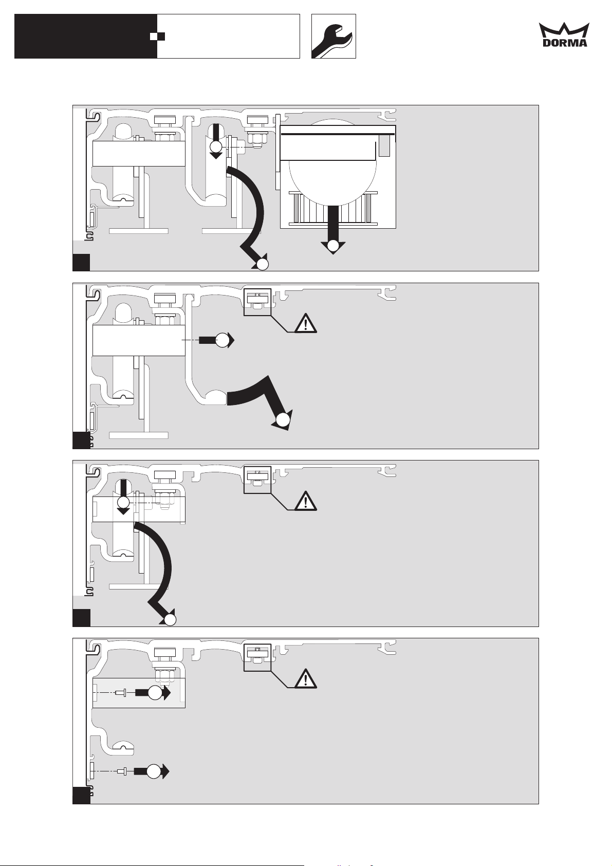
Montage
Laufwagen schnellläufer, Zahnriemen,
2
Mini-Drive-Unit und Umlenkung entfernen.
Montageschiene zur positionierung der MDU
nicht entfernen.
Laufprofil Laufwagen schnellläufer entfernen.
3
Laufwagen langsamläufer entfernen.
4
Antriebsprofil vom Montageprofil bzw. LM-Träger
5
lösen.
Antriebseinheit in Wandmontage montieren
- Antriebseinheit von der Montageplatte
40A40A
6A
entfernen
- Bohrgruppen markieren. LH + 50 beachten.
7A
Massangaben siehe Bild.
- Löcher bohren.
- bei Mauerwerk Dübel einstecken.
- bei Stahlkonstruktionen Gewinde schneiden
- Montageplatte mit Senkkopfschrauben
8A
anschrauben.
- Montageplatte ggf. unterfüttern um
Unebenheiten auszugleichen.
Antriebseinheit auf die Montageplatte hängen,
ausrichten und fest anschrauben.
Antriebseinheit montieren, in Durchgangsmontage
Bei Mauerwerk müssen Schwerlastdübel verwen-
6B
det werden. Die Dübel müssen bauseits gestellt
werden.
Langlochbohrungen anreissen/markieren.
- Löcher bohren.
- bei Mauerwerk: Dübel einstecken.
- bei Stahlkonstruktionen:
Ø 6,4 mm Löcher bohren und
M 8 Gewinde schneiden.
Wandbefestigungen durch die Langlöcher
7B
anschrauben
Zusätzliche Stützwinkel anschrauben.
8B
- Vierkantmuttern in die Profilkanäle des
9B
LM Trägers einschieben.
- LM-Träger in die Wandbefestigung
einhängen, ausrichten und anschrauben.
- Die weitere Schrauben für
Wandbefestigungen anbringen.
- Bohrungen durch die Ø11 Löcher anreißen,
- Ø10 bohren, dübeln und verschrauben
Antriebsprofil einhängen, ausrichten und fest
10B
anschrauben.
29
Page 30

DORMA
30
Montageanleitung
12/06
02
40A11B
WN 057067 45532
12B
13a
13b
14a
14b
14c
15
16A/B
18A/B
19A/B
20A/B
21A/B
22a/b/c
23
24
ES 200 T Easy
ES 200 T
ES 200 T-2D
Bei Anlagen mit Seitenteilen:
Wandanschlußprofile (U-Profile) gemäß Maßangaben in der Zeichnung befestigen.
- Bohrungen markieren.
- Löcher bohren.
- bei Mauerwerk, Dübel einstecken.
- bei Stahlkonstruktionen, Gewinde schneiden.
- Wandanschlußprofile anschrauben und
ausrichten.
- Wandanschlußprofile fest anschrauben,
Seitenteile in die Wandanschlußprofile
einschieben, ausrichten und fixieren.
Laufschiene säubern.
Bodenführung montieren
Die Bodenführung, je nach Gegebenheit, mit
dem Gebäude oder mit dem Seitenteil
verschrauben.
Wenn Unterflurführung diese einbetonieren
Laufwagen langsamläufer einhängen
Laufwagen langsamläufer positionieren
Lichtschranken-Kabel einführen.
17B
Fahrflügel langsamläufer einstellen.
Fahrflügel mit passendem Abstand zum
Fußboden einstellen.
Bügel oberhalb der Hauptschliesskante:
- Innensechskantschrauben lösen.
Bügel oberhalb der Nebenschließkante:
- Innensechskantschrauben lösen.
- Höheneinstellung mit der Sechskantmutter
vornehmen.
- Innensechskantschrauben wieder festan-
ziehen.
- Tür aufschieben, die Seitendichtungen müssen
parallel zu den Seitenteilen (Wand) verlaufen.
- Seitenteilen (Wandabschlußprofil) bei Bedarf
Bügel oberhalb der Hauptschliesskante:
- Höheneinstellung mit der Sechskantmutter
vornehmen.
- Innensechskantschrauben wieder festan-
ziehen.
Zum Schutz der Lichtschranken-Kabel
im Bereich des Laufprofils,
Schrumpfschläuche über die
Lichtschranken-Kabel ziehen.
Lichtschranken-Kabel am Antriebsprofil
anschrauben.
Schrauben nicht zu fest anziehen damit
die Kabelisolierung nicht zerstört wird.
U-Kabelkanalstücke einsetzen
Lichtschranken-Kabel an die Steuerung
anschließen, siehe Anschlussplan.
Fahrflügel langsamläufer einhängen
justieren.
Entgleisungsschutz einstellen.
Entgleisungsschutz der Laufköpfe entspannen
25
und einstellen.
- Schrauben in den Langlöchern der Laufwagen
lösen.
- Entgleisungsschutz auf 0,5 mm Abstand zum
Lauf- und Montageprofil einstellen.
- Fahrflügel auf Leichtgängigkeit überprüfen.
- Schrauben wieder fest anziehen.
Laufprofil Laufwagen schnellläufer anschrauben
26A
26B
Durchführung Lichtshrankenkabel beachten
27A
27B
Schutzprofil für Lichtschrankenkabel und
28A
Lichtschranken anbringen.
28B
Laufwagen schnellläufer einhängen und
29a
29b
29c
mit Laufwagen langsamläufer verbinden
30a
30b
30c
Fahrflügel schnellläufer einhängen
31a
31b
31c
Fahrflügel schnellläufer einstellen
Fahrflügel mit passendem Abstand zum
32
Fußboden einstellen.
33
Bügel oberhalb der Hauptschliesskante:
- Innensechskantschrauben lösen.
Bügel oberhalb der Nebenschließkante:
- Innensechskantschrauben lösen.
- Höheneinstellung mit der Sechskantmutter
vornehmen.
- Innensechskantschrauben wieder festan-
ziehen.
- Tür aufschieben, die Seitendichtungen müssen
parallel zu den langsamen Fahrflügel verlaufen.
Bügel oberhalb der Hauptschliesskante:
- Höheneinstellung mit der Sechskantmutter
vornehmen.
- Tür zuschieben, dann wieder einige Millimeter
aufschieben und den Öffnungsspalt der
Dichtungen über die gesamte Höhe auf
gleichen Abstand kontrollieren.
- Innensechskantschrauben wieder fest
anziehen.
30
Page 31

DORMA
31
Montageanleitung
12/06
03
34
WN 057067 45532
35a
35b
36ab
37ab
35c
36c
37c
38a
38b
38c
39a
39b
39c
39d
ES 200 T Easy
ES 200 T
ES 200 T-2D
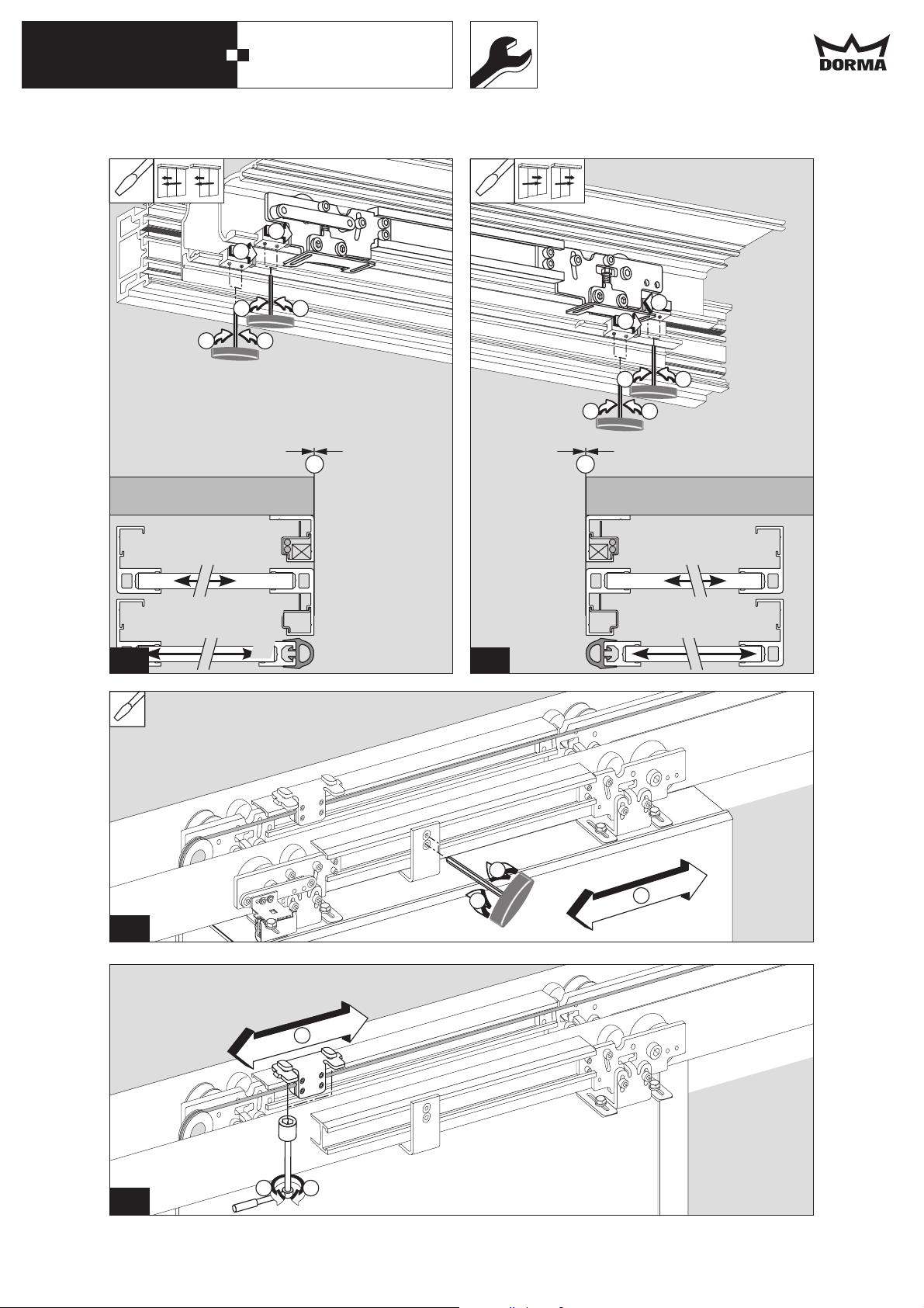
Entgleisungsschutz einstellen.
Entgleisungsschutz der Laufköpfe entspannen
und einstellen.
- Schrauben in den Langlöchern der Laufwagen
lösen.
- Entgleisungsschutz auf 0,5 mm Abstand zum
Lauf- und Montageprofil einstellen.
- Fahrflügel auf Leichtgängigkeit überprüfen.
- Schrauben wieder fest anziehen.
Endanschläge und Öffnungsweite einstellen.
Zweiflügelig
- Endanschläge lösen.
- Fahrflügel manuell auf volle
Öffnungsweite schieben und festsetzen.
- Endanschläge an die Fahrflügel anschieben.
- Endanschläge festschrauben.
Fahrflügel zueinander justieren.
Seilverbindung zum Fahrflügel schnellläufer
lösen.
Türflügel positionieren.
Seilverbindung wieder fest anziehen.
Wenn nötig zusätzliche Anbindung
Seil - Antriebsprofil nachjustieren.
Endanschläge und Öffnungsweite einstellen.
Vierflügelig
- Endanschläge lösen.
- Fahrflügel manuell auf volle
Öffnungsweite schieben und festsetzen.
- Endanschläge an die Fahrflügel anschieben.
- Endanschläge festschrauben.
Fahrflügel zueinander justieren.
Seilverbindung zum Fahrflügel schnellläufer
lösen.
Türflügel positionieren.
Seilverbindung wieder fest anziehen.
Wenn nötig zusätzlich Anbindung
Seil - Antriebsprofil nachjustieren.
Mini Drive Unit und Umlenkung einsetzen
Mini Drive Unit einhängen, justieren und
befestigen.
EasyEasy
ES 200 T
ES 200 T
ES 200 T-2D
Umlenkung (Verriegelung) montieren
Easy
EasyEasy
Zahnriemen, Blendenhalter, Zubehör und
40
Optionen einbauen.
41
Zubehör und Optionen gemäß der den jeweiligen
42
Produkten beiliegenden Montageanleitung
montieren.
43
Kabelführung vor MDU einsetzen
44
Schliesskante einstellen
Türanlage schließen
45
Schliesskante (SK) auf Anlagenmitte (AM) setzen
Von der Innenseite gesehen:
- Am linken Fahrflügel, Verbindung zwischen
46a
Laufwagen und Zahnriemen lösen.
46b
- Beide Fahrflügel manuell verschieben, bis die
Schließkante (SK) der Anlagenmitte (AM)
entspricht.
- Verbindung zwischen Laufwagen und
Zahnriemen wieder fest anziehen.
Größere Abweichungen SK zu AM, wie im Bild
46c
dargestellt ausgleichen.
- Zahnriemen um einen oder mehrere Zähne
versetzen.
Zahnriemen spannen
Zahnriemen von Hand kräftig vorspannen und
47a
sichern.
Spannvorrichtung gegen Umlenkung
48a
(Verriegelung) andrücken und Hammerkopfschraube anziehen
Umlenkung anlösen
49a
Spannvorrichtungsschraube anziehen bis Feder
50a
auf 33 mm zusammengedrückt ist.
Umlenkung (Verriegelung) fest anziehen.
Zahnriemen von Hand kräftig vorspannen und
47b
sichern.
Hammerkopfschraube der Spannvorrichtung
anziehen
Spannvorrichtungsschraube anziehen bis
48b
Schraubenkopf und Halterungsende eine Linie
bilden.
Umlenkung (Verriegelung) fest anziehen.
Verriegelung (Option) einstellen
Fahrflügel schliessen
51
Käfigeinheit lösen
52
Verriegelungsbolzen einschieben
53
Käfigeinheit einstellen
54a
54b
Käfigeinheit festsetzen
55
31
Page 32

DORMA
32
Montageanleitung
12/06
04
56
WN 057067 45532
57
58A
58B
59
ES 200 T Easy
ES 200 T
ES 200 T-2D
Zahnriemen justieren:
- Rechte Befestigungsschraube der Umlenkrolle
lösen.
- Einstellschraube (Madenschraube) solange
hineindrehen bis der Riemen wieder frei läuft.
- Befestigungsschraube auf der Umlenkrolle
wieder fest anschrauben.
Alle elektrischen Anschlüsse gemäß den
Anschlußplänen herstellen.
Innen-Verkleidung anpassen/ablängen und
einhängen.
Die Scharnierprofilstücke in die Innenverkleidung
einschieben.
Stirnbleche passgenau ablängen und einsetzen.
Damit die Stirnbleche sauber eingesetzt werden
können:
An der Innenverkleidung gemäß Massangabe die
Ecken abfeilen.
Vierkantmutter in der Nut einführen und
Schutzleiterkabel an der Innenverkleidung
befestigen.
Halter für die Stirnbleche einsetzen und anschrauben. Stirnbleche anschrauben.
Innenverkleidung anbringen
Beginnend von der Mitte nach aussen gehend.
60
Die Innenverkleidung mit den eingeschobenen
61
Scharnierprofilstücken von Hand in das Montageprofil eindrücken.
Innenverkleidung öffnen, festsetzen und mit
62
Schutzleiterkabel erden.
63
64
Für den Test nach dem Einbau:
- Netzspannung anbringen
65a
- Akku anschliessen.
66a
- Eine Testfahrt durchführen.
65b
- Bis zur endgültigen Inbetriebnahme Akku
abziehen.
66b
65c
66c
Änderungen vorbehalten
Subject to change without notice
32
DORMA GmbH + Co.KG Postfach 40 09D-58247 Ennepetal • Breckerfelder Straße 42-48 D-58256 Ennepetal
Automatic Division Tel. +49 (0) 23 33 / 793-0 • Fax +49 (0) 23 33 / 79 34 95 • www.dorma.com
Page 33

DORMA
33
Installation instruction
12/06
Drawing and text with designation e.g.
01
belong to the wall installation
Drawing and text with designation e.g.
WN 057068 45532
belong to the corridor installation
Drawing and text with designation e.g.
are mounting versions
ES 200 T Easy
ES 200 T
ES 200 T-2D
1A
1B
1a
2A
2B
1b
Installation
3A
3B
2
1c
Remove fast carrier, toothed belt, Mini Drive Unit
and pulley (locking device).
Don’t remove the fixing rail of the MDU.
Before installation
Work on electrical equipment may only be
performed by properly qualified electricians.
Where cables are shortened, connection bayonets
must be used.
Power supply (on site) with 16 A fuse protection
is required.
The connecting cable must be double insulated,
for example: NYM. Do not use flat webbed house
wires.
The instructions accompanying the optional
extras and accessories have to be observed.
The working area has to be secured when it
comes to overhead work in entrance or passage
areas.
Falling items or tools might cause injuries.
The following documentations are enclosed with
the Mini Drive Unit::
- Commissioning
- Adjustment
- Functional test
- Information regarding maintenance and care
- Instruction manual
- Troubleshooting instructions
- Connection diagrams
- Wiring diagrams
- System adjustment
Direct wall installation
1A
Main profils and their positions.
Corridor installation with aluminium girder (LM)
1B
Main profils and their positions.
Pay attention to the structural conditions and
select suitable fixing material.
The fixing material is not supplied by DORMA.
With wood – wood screws,
With masonry – heavy-duty dowels,
With steel structure – threaded screws.
Remove track profile of fast carrier.
3
Remove slow carrier.
4
Remove header profile from mounting profile or
5
aluminium girder (LM)
Installation of operator with wall mounting
- Remove header profile from mounting profile or
40A40A
6A
aluminium girder (LM)
7A
Installation of operator with wall mounting
- Mark drill holes.
Consider clear passage height + 50.
See picture for dimensions.
- Drill holes.
- With masonry:
8A
- With steel structure: cut threads.
- Screw down mounting plate with countersunk
screws.
- Pad mounting plate if required.
Antriebseinheit auf die Montageplatte hängen,
ausrichten und fest anschrauben.
Installation of operator with corridor mounting
6B
With masonry, heavy-duty dowels have to be
used. The dowels must be supplied by others.
Mark the drill holes for the oblong holes.
- Drill holes.
- With masonry: Insert dowels.
- With steel structure:
Screw down the bracket for the corridor
7B
installation through the oblong holes.
Screw down additional support angles.
8B
9B
- Insert square nuts into the profile slots of the
aluminium girder (LM).
- Fit the aluminium girder (LM) onto the bracket
for the corridor installation, align and screw
down.
- Screw down the further screws for the bracket
for the corridor installation.
- Mark drill holes through the holes with a
diameter of 11 mm,
- drill Ø 10 mm holes, insert dowels and screw
down.
Fit the header profile, align and screw down tight.
10B
insert dowels.
Drill holes with a diameter of 6.4 mm
and cut M 8 threads.
33
Page 34

DORMA
34
Installation instruction
12/06
02
11B
WN 057068 45532
12B
13a
13b
ES 200 T Easy
ES 200 T
ES 200 T-2D
Systems with side screens:
Mount wall connection profile for systems without
side screens according to the dimensions
indicated in the drawing.
- Mark and drill holes.
- With masonry:
- With steel structure: cut threads
- Align and screw down wall connection profiles
for systems without side screens.
- Screw down tight the wall connection profiles
for systems without side screens.
Insert, align and fix side screens to the wall
connection profiles.
Clean track rail.
Installation of floor guide rail
Screw down floor guide rail to building or side
screen depending on structural conditions.
Where there is a floor guide, encase in concrete.
insert dowels.
Adjustment of derailing protection.
Release and adjust the derailing protection of the
25
carrier heads.
- Undo the bolts in the oblong holes of the
carriers.
- Adjust derailing protection to a clearance of
0.5 mm with respect to the track rail and the
mounting profile.
- Check sliding leaf for smooth running.
- Re-tighten the screws.
Screw down track rail of fast carrier.
26A
26B
Pay attention to the position of the light barrier
27A
cable.
27B
Attach cover profile for light barrier cable and
28A
light barriers.
28B
Fit slow carrier.
14a
14b
14c
Position slow carrier.
15
Insert light barrier cable.
16A/B
Use shrinking tube in the area of the track rail
17B
to protect the light barrier cable.
18A/B
Screw down light barrier cable to header
profile.
19A/B
20A/B
Do not screw down too tight to avoid
damage of cable insulation.
Insert U-shaped cable channels.
21A/B
See connection diagram for connection of
light barrier cable to control unit.
Fit slow carrier of active leaf
22a/b/c
Adjustment of slow carrier of sliding leaf.
Adjust the sliding leaf so that it has a suitable
23
distance to the floor.
24
Bracket above main closing edge:
- Relax countersunk screws.
Bracket above secondary closing edge:
- Relax countersunk screws.
- Adjust height via hexagon socket screw.
- Tighten hexagon socket screws.
- Open the door and make sure that the side
seals are parallel with the side screens (wall).
- Adjust side screens (wall connection profile for
systems without side screens), if required.
Bracket above main closing edge:
- Adjust height via hexagon socket screw.
- Tighten hexagon socket screws.
Fit fast carrier.
29a
29b
29c
Connect it to the slow carrier
30a
30b
30c
and fit sliding leaf to fast carrier.
31a
31b
31c
Adjustment of sliding leaf of fast carrier
32
Adjust the sliding leaf so that it has a suitable
33
distance to the floor.
Bracket above main closing edge:
- Relax countersunk screws.
Bracket above secondary closing edge:
- Relax countersunk screws.
- Adjust height via hexagon socket screw.
- Tighten hexagon socket screws.
- Open the door and make sure that the side
seals are parallel with the side screens that are
attached to the slow carriers
Bracket above main closing edge:
- Adjust height via hexagon socket screw.
- Close the door and then reopen it a few
millimetres. Check the gap between the center
seals over its entire height to ensure good
parallelism.
- Tighten hexagon socket screws.
34
Page 35

DORMA
35
Installation instruction
12/06
03
34
WN 057068 45532
35a
35b
36ab
37ab
35c
36c
37c
38a
38b
38c
39a
39b
39c
39d
ES 200 T Easy
ES 200 T
ES 200 T-2D
Adjustment of derailing protection
Release the derailing protection of the carrier
heads and adjust.
- Undo the bolts in the oblong holes of the
carriers.
- Adjust derailing protection to a clearance of
0.5 mm with respect to the track rail and the
mounting profile.
- Check sliding leaf for smooth running.
- Re-tighten the screws.
Adjustment of end stops and opening width.
Double-leaf door
- Relax end stops.
- Move both sliding leaves manually to the full
opening width and secure in this position.
- Move the end stops along to meet the sliding
leaves.
- Screw down end stops.
Adjustment of sliding leaves to each other
Relax the belt connection of the sliding leaf
that is attached to the fast carrier.
Adjust the sliding leaf.
Retighten the connection thoroughly.
Readjust the additional connection of the belt
and the header profile, if required.
Adjustment of end stops and opening width.
Four-leaf
- Relax end stops.
- Move both sliding leaves manually to the full
opening width and secure in this position.
- Move the end stops along to meet the sliding
leaves.
- Screw down end stops
Adjustment of sliding leaves to each other.
Relax the belt connection of the sliding leaf that
is attached to the slow carrier.
Adjust the sliding leaf.
Retighten the connection thoroughly.
Readjust the additional connection of the belt
and the header profile, if required.
Installation of Mini Drive Unit and pulley (locking
device)
Fitting, adjustment and mounting of Mini Drive
Unit.
ES 200 T Easy
ES 200 T
ES 200 T-2D
Install pulley (locking device).
Install toothed belt, cover bracket, accessories
40
and optional extras.
41
Install the accessories and the optional extras in
42
accordance with the installation instructions
accompanying the relevant products
43
Fit cable channel in front of Mini Drive Unit.
44
Adjustment of closing edge.
Close door system
45
Adjustment of main closing edge (SK) to the
center of the door system (AM).
Regarded from the inside
- Release connection between carrier and
46a
toothed belt at the left sliding leaf.
46b
- Move both sliding leaves manually until the
main closing edge (SK) meets the center of the
door system (AM).
- Tighten the connection between the carrier
and the toothed belt.
Mayor discrepancies between the main closing
46c
edge (SK) and the center of door system (AM)
must be adjusted as explained in the picture.
Move toothed belt by one or several tooth pitches
along.
Tensioning of toothed belt
Pretension toothed belt forcefully by hand and
47a
secure.
Press tensioning device against pulley (locking
48a
device) and tighten hammerhead screw.
Relax pulley (locking device).
Tighten screw of locking device until spring is
49a
tensioned to a length of 33 mm.
50a
Screw down pulley (locking device) tight.
Pretension toothed belt forcefully by hand and
47b
secure.
Tighten hammerhead screw of tensioning device.
Tighten screw of tensioning device until the head
48b
of the screw and the edge of the device are
aligned.
Screw down pulley (locking device) tight.
Adjustment of locking device (optional)
Close sliding leaf
51
Relax cage
52
Insert lock bolt
53
Adjust cage
54a
54b
and secure cage.
55
35
Page 36

DORMA
36
Installation instruction
12/06
04
56
WN 057068 45532
57
58A
58B
59
60
61
62
63
64
65a
66a
65b
66b
65c
66c
ES 200 T Easy
ES 200 T
ES 200 T-2D
Adjustment of toothed belt:
- Release the right fixing screw of the pulley.
- Wind in the adjustment screw (grub screw)
until the toothed belt again runs smoothly.
- Tighten the fixing screw of the pulley.
All the electrical connections have to be made
in accordance with the connection diagrams.
Adjustment, trimming and installation of internal
cover.
Insert hinge profiles into internal cover.
Trim and install end plates.
In order to ensure the proper installation of the
end plates:
Break the edges of the internal cover according
to the stated dimensions.
Insert the square nut into the groove and fix the
PE cable to the internal cover.
Insert and screw down end plate girder.
Screw down end plates.
Mounting of internal cover.
Starting in the center and progressing to the
sides. Insert hinge profile into internal cover and
install manually into mounting profile.
Open and fix the internal cover and use PE cable
to ground it.
For testing purposes following the installation:
- Connect system to power supply
- Connect rechargeable battery pack.
- Perform a test cycle.
- Remove rechargeable battery pack until final
commissioning.
Änderungen vorbehalten
Subject to change without notice
36
DORMA GmbH + Co.KG Postfach 40 09D-58247 Ennepetal • Breckerfelder Straße 42-48 D-58256 Ennepetal
Automatic Division Tel. +49 (0) 23 33 / 793-0 • Fax +49 (0) 23 33 / 79 34 95 • www.dorma.com
Page 37

DORMA
37
ES 200 T
Easy
ES 200 T
ES 200 T-2D
Technische Daten
11/06
Anschlußspannung
057069 45532
Absicherung
Spannungsversorgung für externe Geräte
Leistungsaufnahme: max.
Programm-Eingang
AUS
AUTOMATIC
DAUERAUF
TEILÖFFNUNG
AUSGANG
Daten und Merkmale
Öffnungsweite, in mm, 2-flügelig
Öffnungsweite, in mm, 4-flügelig
Türgewicht, in kg max., 2-flügelig
Türgewicht, in kg max., 4-flügelig
· = ja
·
ES 200 T Easy ES 200 T ES 200 T-2D
230 V +/- 10% / 50 Hz
-
27VDC/500mA 27VDC/2A
180 W 250 W 250 W
·
·
·
·
800 - 2400
1400 - 4000
2x50
4x43
·
·
·
·
800 - 2400
1400 - 4000
2x75
4x75
·
·
·
·
1000 - 2400
1400 - 4000
2x75
4x65
D
Einstellungen
Öffnungsgeschwindigkeit
Schließgeschwindigkeit (bis 71 kg)
SchleichgeschwindigkeitAUF
Schleichgeschwindigkeit ZU
Bremsrampe AUF Bremsverzögerung AUF
Bremsrampe ZU
Bremsrampe Reversieren
Offenhaltezeit
Offenhaltezeit NACHT/BANK
Auffahrverzögerung NACHT/BANK
Teilöffnung
Schleichfahrtstrecke AUF
Schleichfahrtstrecke ZU
Beschleunigung AUF
Beschleunigung ZU
Kraftbegrenzung AUF
Kraftbegrenzung ZU
Einstellbereich
min. - max.
10 cm/s 50 cm/s
10 cm/s 50 cm/s
--
--
--
--
--
0 s 30 s
0 s 30 s
--
25 cm Offen
--
--
--
--
Auto.
Auto.
Einstellbereich
min. - max.
10 cm/s 75 cm/s
10 cm/s 50 cm/s
3 cm/s 9 cm/s
3 cm/s 9 cm/s
19
19
19
0 s 180 s
0 s 60 s
0s 10
25 cm Offen
0cm 30cm
0cm 30cm
19
19
50 N 310 N
50 N 310 N
Einstellbereich
min. - max.
10 cm/s 75 cm/s
10 cm/s 50 cm/s
3 cm/s 9 cm/s
3 cm/s 9 cm/s
19
19
19
0 s 180 s
0 s 60 s
0s 10
25 cm Offen
0cm 30cm
0cm 30cm
19
19
50 N 310 N
50 N 310 N
Änderungen vorbehalten
DORMA GmbH + Co.KG Postfach 40 09 D-58247 Ennepetal • Breckerfelder Straße 42-48 D-58256 Ennepetal
Tel. +49 (0) 23 33 / 793-0 • Fax +49 (0) 23 33 / 79 34 95 • www.dorma.comAutomatic division
Page 38

DORMA
38
ES 200 T
Easy
ES 200 T
ES 200 T-2D
Technical Data
11/06
Power supply data
057069 45532
Fuse
Power supply for external accessories
power consumption: max.
Function programs
OFF
AUTOMATIC
PERMANENT OPENING
PARTIAL OPENING
EXIT
Data and characteristics
Door leaf width
Door leaf width
Door leaf weight
Door leaf weight
, in mm, 2-panel sliding door
, in mm, 4-panel sliding door
, in kg max., 2
, in kg max., 4-panel
· = yes
·
-panel
ES 200 T Easy ES 200 T ES 200 T-2D
230 V +/- 10% / 50 Hz
-
27VDC/500mA 27VDC/2A
180 W 250 W 250 W
·
·
·
·
800 - 2400
1400 - 4000
2x50
4x43
·
·
·
·
800 - 2400
1400 - 4000
2x75
4x75
·
·
·
·
1000 - 2400
1400 - 4000
2x75
4x65
GB
Parameter
Opening speed
Closing speed (up to 71 kg)
Creep speed OPENING
Creep speed CLOSING
brake ramp
brake ramp CLOSE
brake ramp reversing
Hold open time
Hold open time NIGHT/BANK
Delayed opening
Partial Opening
Creep speed distance OPENING
Creep speed distance CLOSING
Acceleration OPENING
Acceleration CLOSING
Force limitation
Force limitation CLOSING
OPEN braking deceleration OPEN
NIGHT/BANK
OPENING
setting range
min. - max.
10 cm/s 50 cm/s
10 cm/s 50 cm/s
--
--
--
--
--
0 s 30 s
0 s 30 s
--
25 cm Open
--
--
--
--
Auto.
Auto.
setting range
min. - max.
10 cm/s 75 cm/s
10 cm/s 50 cm/s
3 cm/s 9 cm/s
3 cm/s 9 cm/s
19
19
19
0 s 180 s
0 s 60 s
0s 10
25 cm Open
0cm 30cm
0cm 30cm
19
19
50 N 310 N
50 N 310 N
setting range
min. - max.
10 cm/s 75 cm/s
10 cm/s 50 cm/s
3 cm/s 9 cm/s
3 cm/s 9 cm/s
19
19
19
0 s 180 s
0 s 60 s
0s 10
25 cm Open
0cm 30cm
0cm 30cm
19
19
50 N 310 N
50 N 310 N
Subject to change without notice
DORMA GmbH + Co.KG Postfach 40 09 D-58247 Ennepetal • Breckerfelder Straße 42-48 D-58256 Ennepetal
Tel. +49 (0) 23 33 / 793-0 • Fax +49 (0) 23 33 / 79 34 95 • www.dorma.comAutomatic division
Page 39

DORMA
39
Drucktechnisch bedingte leere Seite
Blank page on account of printing technology
Page 40

DORMA
40
Drucktechnisch bedingte leere Seite
Blank page on account of printing technology
Page 41

DORMA
41
Sicherheit
DORMA
Sicherheitshinweise
06/06
1. Bestimmungsgemäßer Gebrauch
Türantriebe dienen ausschließlich zum Öffnen und Schließen von Türen.
WN 057014 45532
2. Produktspezifische Eigenarten
3. Normen, Gesetze, Richtlinien und Vorschriften
Das Spielen mit den Anlagen/Geräten durch kleine Kinder ist nicht gestattet.
Kinder nicht mit den Anlagen oder fest montierten Regel- und/oder Steuereinrichtungen
spielen lassen. Fernsteuerungen außerhalb der Reichweite von Kindern halten.
DORMA Türantriebe werden wie folgt eingesetzt:
- DORMA CD 80 an Drehflügel-Anschlagtüren.
- DORMA ED 200
- DORMA CD 400
- DORMA ES 200
- DORMA ES 200 Easy
- DORMA ES 200 2D an Schiebetüren und an Flucht- und Rettungswegtüren.
4
an Drehflügel-Anschlagtüren und an Brandschutztüren.
4
an Schiebetüren.
4
4
Der neueste Stand der allgemeingültigen und länderspezifischen Normen, Gesetze,
Richtlinien und Vorschriften ist einzuhalten.
D
4. Haftungsbeschränkung
Der Antrieb darf nur gemäß seiner bestimmungmäßigen Verwendung eingesetzt werden.
Eigenmächtige Änderungen an der Anlage schließen jede Haftung durch die DORMA GmbH +
Co. KG für daraus resultierende Schäden aus.
5. Dokumentationsunterlagen
WICHTIGE ANWEISUNGEN FÜR SICHERE MONTAGE.
ALLE ANWEISUNGEN IN DEN DOKUMENTATIONSUNTERLAGEN BEACHTEN.
(z.B Briefumschlag mit der Aufschrift Dokumentationsunterlagen)
FALSCHE MONTAGE KANN ZU ERNSTHAFTEN VERLETZUNGEN FÜHREN.
FÜR DIE SICHERHEIT VON PERSONEN IST ES WICHTIG, DIESEN ANWEISUNGEN FOLGE ZU LEISTEN.
DIESE ANWEISUNGEN SIND AUFZUBEWAHREN.
6. Allgemeine Hinweise zur Montage
Bauseitige Vorbereitung
Den Arbeitsplatz gegen unbefugtes Betreten sichern.
Herunterfallende Teile oder Werkzeuge können zu Verletzungen führen
Die Befestigungsart und die Befestigungsmittel, wie z.B. Schrauben und Dübel, müssen auf
jeden Fall den baulichen Gegebenheiten angepaßt werden (Stahlkonstruktion, Holz, Beton
usw.).
Vor dem Einbau des Antriebs den/die Türflügel auf einwandfreien mechanischen Zustand und
Leichtgängigkeit prüfen.
Page 42

DORMA
42
Sicherheit
Nach der Montage
Im Anschluss an die Montage sind die Einstellungen und die Funktionsweise des Antriebes
und der Schutzeinrichtungen zu überprüfen.
Die hier beschriebene Montage des Antriebs ist ein Beispiel. Bauliche oder örtliche
Gegebenheiten, vorhandene Hilfsmittel oder andere Umstände können eine andere
Vorgehensweise sinnvoll machen.
7. Restrisiken
An automatischen Türen können Quetsch-, Scher-, Stoß- und Einzugsgefahren entstehen. Je
nach baulicher Gegebenheit, Türvariante und Absicherungsmöglichkeit können Restgefahren
nicht ausgeschlossen werden. Zum Beispiel kraftbegrenztes Anstoßen oder Quetschen.
Nebenschließkante
8. Wartung und Pflege
Die Anlage ist vor der ersten Inbetriebnahme und je nach Bedarf, jedoch mindestens einmal
jährlich, von einem Sachkundigen zu prüfen und ggf. zu warten.
Die Wartung muss regelmäßig, nach den Vorgaben des Herstellers, von einer dafür
ausgebildeten Person durchgeführt werden.
(BG-Regel für kraftbetätigte Türen, Fenster und Tore. BGR 232/DIN 18650)
Vor Instandhaltungsarbeiten (Reinigung oder Wartung) muss der Antrieb abgeschaltet und
gegen irrtümliches und unbefugtes Einschalten gesichert werden.
Gegenschließkante
Hauptschließkante
Hauptschließkante
Nebenschließkante
Wir empfehlen, mit DORMA darüber einen Wartungsvertrag abzuschließen.
DORMA GmbH + Co.KG Postfach 40 09 D-58247 Ennepetal Breckerfelder Straße 42-48 D-58256 Ennepetal
Tel. +49 (0) 23 33 / 793-0 Fax +49 (0) 23 33 / 79 34 95 www.dorma.de
Page 43

DORMA
43
Safety
DORMA
Safety advice
06/06
1. Intended application
Door operators are only designed to open and close doors.
WN 057014 45532
2. Product-specific characteristics
3. Standards, laws, codes and regulations
Small children are not allowed to play with the systems/appliances.
Do not allow children to play with the systems or rigidly mounted adjustment and/or control
devices. Keep the remote controls out of reach of children
DORMA operators are applied as follows:
- DORMA CD 80 at swing doors.
- DORMA ED 200
- DORMA CD 400
- DORMA ES 200
- DORMA ES 200 Easy
- DORMA ES 200 2D at sliding doors and at doors with application in emergency exits
The latest versions of the common and country-specific standards, laws, codes and
regulations have to be observed.
4
at swing doors and at fire and smoke doors.
4
at sliding doors.
4
4
and escape routes.
GB
4. Limitation of liabilityg
The operator must only be applied according to its intended application.
The DORMA GmbH + Co. KG does not accept any liability for damages resulting from
unauthorized modifications of the system.
5. Documentation
IMPORTANT INSTRUCTIONS FOR THE SAFE INSTALLATION OF THE SYSTEM.
ALL INSTRUCTIONS MENTIONED IN THE DOCUMENTATION HAVE TO BE OBSERVED.
(e.g. an envelope reading documentation)
AN INCORRECTLY PERFORMED INSTALLATION MIGHT ENTAIL SERIOUS INJURIES.
TO INSURE THE PROPER SAFETY OF PEOPLE, IT IS IMPORTANT TO ABIDE BY THESE
INSTRUCTIONS.
THESE INSTRUCTIONS HAVE TO BE KEPT.
6. General information regarding the installation
Required preparation on site
The working area has to be secured against unauthorised access from other people.
Falling items or tools might cause injuries.
In any case, the way of installation and the mounting equipment, like screws and wall plugs,
have to be adequate with regard to the structural conditions (steel structure, wood, concrete etc.)
Before the installation of the operator, the door leaf/door leaves has/have to be checked for
proper mechanical condition and smooth running.
.
Page 44

DORMA
44
Following installation
Following installation, the setting and the proper function of the operator and the safety
devices have to be checked.
The installation instructions of this operator are only an example. Structural or local
conditions, available tools or other conditions might suggest a different approach.
7. Residual risks
Automatic doors might cause hazards by crushing, shearing, hitting and drawing-in.
Depending on the structural conditions, the door version and the available safety measures,
residual risks cannot be excluded. Like for example by a force-limited hit or crushing.
Safety
.
Secondary closing edge
8. Maintenance and care
Before the first commissioning and depending on requirements, however, at least once a year,
the system has to be checked by a properly qualified technician and serviced if required.
The system has to be serviced at regular intervals by a specially trained person in accordance
with the manufacturer's instructions.
(According to the guidelines for power-operated doors, windows and gates. BGR (Federal
Institute for Geosciences and Natural Resources) 232/DIN 18650)
The operator has to be switched off and secured against unauthorized switching on before
performing maintenance work (cleaning or maintenance).
Opposite closing edge
Main closing edge
Main closing edge
Secondary closing edge
We would recommend to take out a maintenance contract with DORMA.
DORMA GmbH + Co.KG Postfach 40 09 D-58247 Ennepetal Breckerfelder Straße 42-48 D-58256 Ennepetal
Tel. +49 (0) 23 33 / 793-0 Fax +49 (0) 23 33 / 79 34 95 www.dorma.de
 Loading...