

Page 1
DORMA ED800 SERIES
INSTALLATION INSTRUCTIONS
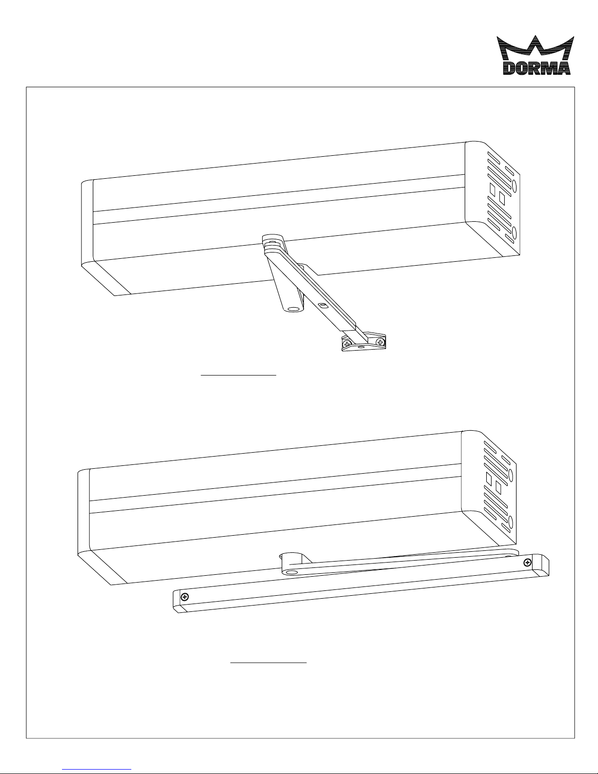
ED800 J
www.dorma-usa.com 1-800-523-8483
ED800 T
08102710 05/07
Page 2

TABLE OF CONTENTS Page
Suggested Tool List……………………………………………………………………………… 3
Functional Detail…………………………………………………………………………………. 4
Installation of Unit...
Introduction……………………………………………………………………………………….. 5
ED 800J Template & Mounting Instructions…………………………………………………... 6
ED 800J x Drop Template & Mounting Instructions………………………………………….. 8
ED 800J x Drop x 830 Template & Mounting Instructions…………………………………… 8
ED 800J x 870 Angle Bracket Template (optional)............................................................. 28
ED 800T Template & Mounting Instructions……………………………………………………11
Valve Adjustments……………………………………………………………………………….. 13
Spring Power Adjustment……………………………………………………………………….. 13
Main Power
Main Power Connection…………………………………………………………………………. 14
Power Cord Option………………………………………………………………………………. 14
Fuse……………………………………………………………………………………………….. 15
Remote Switch Option…………………………………………………………………………... 15
Fire Door Wiring………………………………………………………………………………….. 15
Power Adjustments
Push/Pull Switch…………………………………………………………………………………. 16
Latch/Delay On/Off Switch……………………………………………………………………… 16
Low Energy Function……………………………………………………………………………. 16
Power Assist Function…………………………………………………………………………... 17
Latched Door…………………………………………………………………………………….. 17
ED800 Controller Module Diagram……………………………………………………………. 18
External Connections
Accessory Wire Routing………………………………………………………………………. 19
Open Trigger………………………………………………………………………………….... 20
WS-1 Wall Switch…………………………………………………………………………........ 20
FS-1 Frame Switch…………………………………………………………………………...... 20
RFR Radio Frequency Receiver…………………………………………………………....... 21
WS/RFT-1 Wall Switch……………………………………………………………………....... 21
HH/RFT-1 Transmitter……………………………………………………………………........ 22
KC/RFT-1 Transmitter……………………………………………………………………........ 22
KC/RFT-2 Transmitter……………………………………………………………………........ 22
MS-1 Motion Sensor…………………………...…………………………………………....... 23
Busy Swing (Safety PS-1 Presence Sensor).…………………………………………….... 23
Vestibule Function…………………………………………………………………………….. 24
Latch/Delay Interface…………………………………………………………………………. 25
Strike Interface………………………………………………………………………………… 25
Latch Retraction……………………………………………………………………………..... 25
Auxiliary Power Output……………………………………………………………………….. 26
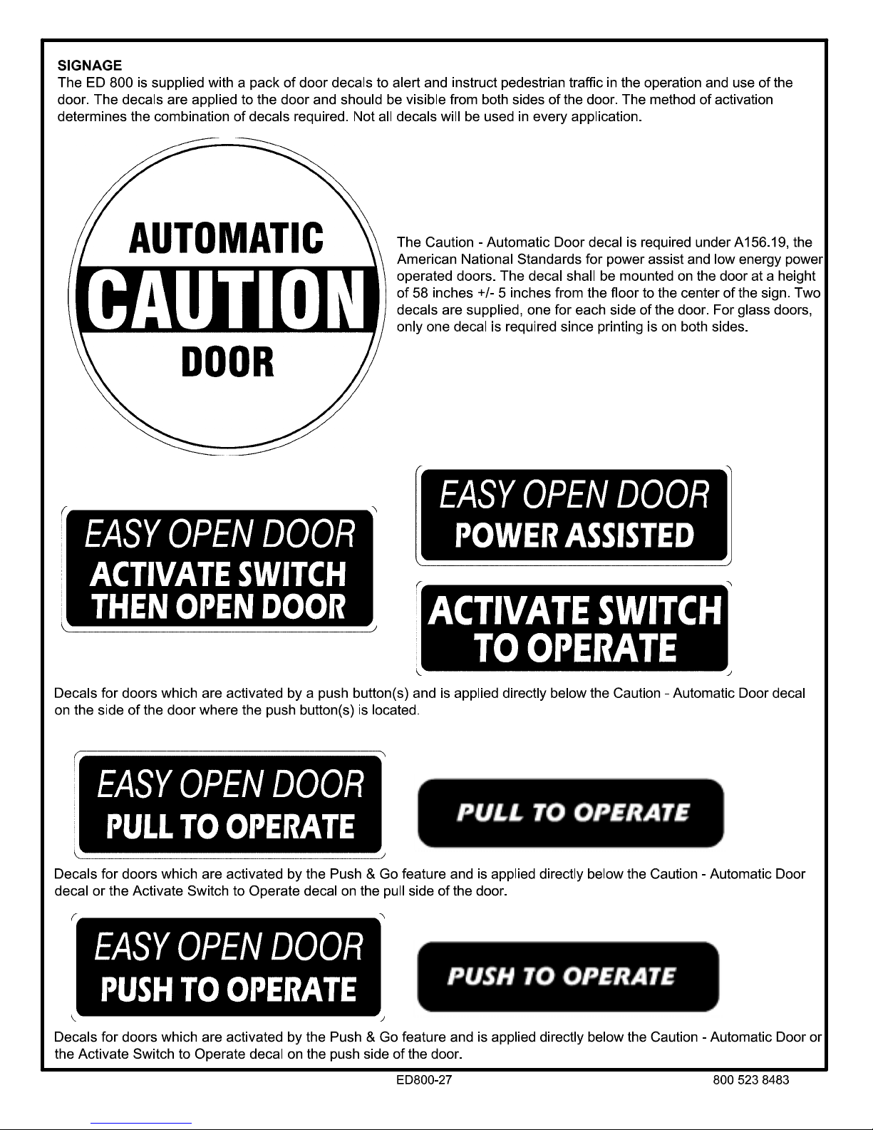
Signage…………………………………………………………………………………………… 27
Electrical Specifications……………………………………………………………………...…. 29
ED800-2
08102710 05/07
Page 3

SUGGESTED TOOL LIST
The following is a list of tools required for the installation of the ED 800. Additional tools may be required for installation of
the various types of actuators and accessories.
1. Long No. 2 Phillips screwdriver
2. No. 3 Phillips screwdriver
3. 1/8" blade screwdriver
4. 3/16" blade screwdriver
5. Tape measure
6. 10" Adjustable wrench
7. Center punch
8. Hammer
9. 5mm Hex key
10. 6mm Hex key
11. 3/8" Drill
12. No. 7 (0.201") Drill bit
13. 5/32" Drill bit
14. 3/8" Drill bit
15. 7/8" Hole saw
16. 1/4 - 20 Tap
17. Safety glasses
18. ED 800 Installation Video
ED800-3
08102710 05/07
Page 4

GENERAL INFORMATION
Functional Detail
The DORMA ED 800 low energy power operator was designed
to make doors accessible, while still providing the good
operating characteristics of a manual door closer.
The ED 800 is based on the DORMA TS83 door closer and
offers the same sweep, latch, backcheck, adjustable spring
power and operating efficiencies. In the normal mode of
operation, the ED 800 will be used as a manual door closer.
Upon activation the unit will open the door, hold the door open
for a predetermined period, and close the door under the
parameters as set forth by ANSI A156.19, Standard for
Power Assist and Low Energy Power Operated Doors.
The mechanical components of the unit consist of a
permanent magnet type DC motor, which drives a lead screw
assembly. The lead screw assembly has a recirculating ball
nut with a shuttle attached to it. The shuttle drives the TS83
door closer.
The electronic components of the unit consist of the motor,
an encoder assembly, a control module, a power transformer,
and additional electronic components and assemblies. The
transformer is powered by line voltage. The transformer
powers the control module. The motor is driven by the
control module. The motor shaft turns an incremental
encoder which indicates the motor velocity to the control
module. The control module responds to external inputs such
as an activation switch and internal door inputs such as an
obstacle encountered in the opening or closing cycle.
The unit also provides a manual rocker switch for a hold
open function. The hold open switch will override all other
inputs, and will hold the door open approximately 5 minutes.
After that period of time, the door will automatically close and
return to the automatic mode. The door can also be closed at
any time by pushing the hold open rocker switch in the
opposite direction.
The ED 800 has two basic functions which can be selected in
the field: Low Energy or Power Assist. The factory setting will
be at Low Energy. In the Low Energy function, when the
door is activated, the door will open within the speed and
force guidelines, per ANSI A156.19. The door will open to a
position which is adjustable between 85° and 115°, and will
stay in the hold open position for a period of time which is
adjustable from 5 to 60 seconds. At the expiration of the
selected time, the door will begin to close. The time delay
commences once the door attains the fully open position, or
when it last receives an actuation input, whichever occurs
later.
In the opening cycle the door will exert a maximum of 15 lbf.
at the latch edge of the door. In the event an obstacle is
encountered, the power will be reduced to the door, so that
the door is held in a balanced state.
While in the balanced state the door can easily be pushed open
or closed, as needed. The door will remain in the balanced state
for the length of time as set by the time delay adjustment. The
time delay commences once there is no longer any door
movement.
In the closing cycle a maximum of 15 lbf. may be generated at
the latch edge of the door. If an obstacle is encountered, the
unit will balance the door. While in this state the door can easily
be pushed open or closed manually, as needed. The door will
remain in the balanced state for the length of time as set by the
time delay adjustment. The time delay commences once there is
no longer any door movement.
If at any time there is a power failure, the unit will operate as a
standard TS83 door closer.
The second basic function is power assist. When the power
assist is activated, the unit responds by opening the door
approximately one inch, to alert the user that the power assist
mode is active. The door can then be opened with a reduced
opening force, which can be adjusted from 1/2 lb. to 5 lbs., as
measured from the latch edge of the door. The reduction of
opening force remains active as long as the unit senses door
movement, plus the duration of the time delay setting. The time
delay will commence after there is no door movement. At the
expiration of the time delay, the door begins to close under the
control of the TS83 door closer.
When the ED 800 is initially energized, it will perform a learn
cycle. If the door is latched and can not open during the learn
cycle, the ED 800 will default to the power requirements of a
typical 36" wide interior door. If an electric strike, magnetic lock
or electric latch retraction device is installed and tied in with the
delay contacts, the ED800 will automatically send a signal to
unlock the strike, magnetic lock or hold back the electric latch.
The ED800 will only go through a full learn cycle when turned on
at the ON/OFF switch. During the learn cycle, the exact closed
position of the door will be established. Also, the ED800 will
open the door a few degrees to determine the amount of force
required to compress the door closer spring and set the door in
motion. From this information, along with the "door width"
setting, the control module can determine the amount of force to
exert on the door so as not to exceed the 15 lbf. maximum
required by the ANSI 156.19 standard. If the ED800 losses
power, (other than the ON/OFF switch) when power is restored
the ED800 does a Secure Learn. The most recent learn cycle is
stored in memory and is used so that the door stays secure
(locked and latched) during and after a power failure.
Activation of the ED 800 can be by any normally open circuit
which is momentarily closed to signal the door. The most basic
means of activating the unit would be a wall switch or frame
switch which is directly wired to the external connector. A radio
frequency receiver along with a radio frequency wall switch
transmitter, or hand held transmitter, can be used if it is
considered too difficult to run wires from the push button to the
unit. For doors that are specifically dedicated for accessibility, a
motion sensor is available to activate the unit. Keep in mind that
when the unit is not activated it will operate as a standard TS83
door closer.
ED800-4 08102710 05/07
Page 5

Another method of activating the door is with the
feature.
activates the door when it is opened more than one inch. It can
be used as the only method of door activation, or it can be used
in conjunction with other external activation means, such as push
buttons. The push and go type activation is intended for
openings that are dedicated to accessibility, since the door is
operating automatically 100% of the time. The push and go
feature is only active when the door is in the fully closed position.
The ED800 has an
The ED800 also has a standard
With this function two units can be interconnected. Upon the
completion of the closing cycle of the first unit, an activation
signal will be sent to the second unit. This activation functions in
both directions. If the interior door is activated first, it will then
signal the exterior door to open. If the exterior door is activated
first, it will then signal the interior door to open.
The ED800 also has a standard
used to control the release of an electric strike, magnetic lock or
the retraction of an electric latch, in conjunction with the
operation of the ED800.
When the ED800 is activated, Form-C relay (NO/ C / NC)
contacts (PINS 6, 7, 8) momentarily change state for up to 1
second to release a strike, magnetic lock or retract a latch.
This is a standard field selectable option which
open trigger
to activate the door opening.
vestibule function
latch delay function.
Push and Go
available.
This is
If required, ED800 operation may be delayed by 1/2 second
when using an electric strike, magentic lock or latch retraction.
Delaying the operator allows a locking device time to release the
door before the ED800 opens it. The delay is enabled using an
On/Off switch on the controller (See page 16). This feature is
only activated when the door is in the closed position, so that
electric strikes, magnetic locks or electric latch bolts are not
operated needlessly.
In addition, the ED 800 offers an
12 volts DC
at
used to power an electric strike or any accessory of compatible
voltage.
The ED 800 also has a
required by the ANSI A156.19 standard, this safety circuit can
provide the ultimate in safe door operation. When the optional
presence sensor is installed, the door will not operate under
power when it detects an obstacle within the swing area of the
door. In addition, the unit will hold the door in the fully opened
position until traffic has cleared from the swing area of the door.
Under no circumstances however, shall the presence sensor
serve to stop an already moving door in the event that the swing
area of the door becomes occupied, once the door is in motion.
In this case, safety is assured by the low opening force, low
opening speed, and obstacle default function of the unit.
, at a maximum of
built-in safety circuit
external output terminal
500 milliamps.
This can be
. While not
, rated
INSTALLATION OF UNIT
Introduction
Prior to installation of the ED800, confirm that the door is in proper working order. Hinges or pivots must be in good condition and
the door must swing freely through the entire opening range anticipated with the ED800.
prior to installation of the ED800.
The ED 800 is a non-handed unit which mounts to the door and frame much the same as a standard door closer. The unit is
designed so that it can be installed by one person. The backplate is equipped with unique slots to aid in installation. Two s
are pre-installed into the frame. The unit is then hung on the two screws until the balance of the screws can be installed and
tightened.
There are four different ways that the ED 800 can be ordered and installed:
ED 800J
header on the push side and the arm shoe is attached to the
door. The standard unit accommodates a reveal from 2 to 6
inches. For reveals of 0 to 4 inches, the C800R bar and shoe
must be specified. For reveals of 4 to 8 inches, the C810R bar
and shoe must be specified. For reveals of 8 to 12 inches, the
C812R bar and shoe must be specified.
ED 800J x Drop
to clear a low ceiling condition on the push side of the door.
This is otherwise similar to the ED 800J.
- Top jamb installation where the unit is attached to the
- Top jamb installation where the unit is located
Ball bearing hinges or needle bearing pivots are recommended for proper ED800 operation.
ED 800J x Drop x 830
ceiling on the push side. The 830 is an arm shoe drop plate
designed to connect the ED 800 arm to a narrow top door rail in
this particular application. This is otherwise similar to the ED
800J x Drop.
ED 800T
header on the pull side and a track arm assembly is attached to
the top of the door.
- Track installation where the unit is attached to the
All door repairs must be performed
crews
- Top jamb drop installation to clear a low
Refer to individual templates for exact dimensional requirements
for each particular application.
preparation template included with the ED 800 when
preparing the door and frame.
Please use the full size
ED800-5 08102710 05/07
Page 6
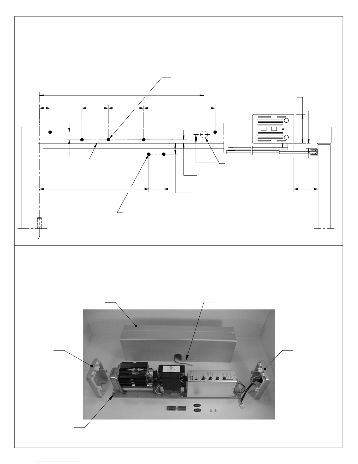
ED 800J - TOP JAMB INSTALLATION TEMPLATE & MOUNTING INSTRUCTIONS
Prepare door and frame according to template.
NOTES:
1. DO NOT SCALE DRAWING.
2. DIMENSIONS ARE IN INCHES/(MM).
3. LEFT HAND DOOR SHOWN.
4. CAUTION: SEX NUTS ARE REQUIRED FOR
ATTACHMENT OF COMPONENTS TO UNREINFORCED
DOORS AND TO WOOD OR PLASTIC FACED
COMPOSITE TYPE FIRE DOORS, UNLESS AN
ALTERNATIVE METHOD IS IDENTIFIED IN THE
INDIVIDUAL DOOR MANUFACTURER'S LISTINGS.
20-11/16
(24)
12-5/8
(321)
3-1/4
(83)
BOTTOM OF FRAME
4-3/8
1-5/16
(33)
3-15/16
(110)
15/16
(525)
(111)
5. SEE CATALOG FOR ARM NUMBER FOR NON STANDARD REVEALS.
6. MAXIMUM OPENING ANGLE 115°.
7. DOORS AND FRAMES MUST BE PROPERLY REINFORCED.
8. IF STOP PROJECTION IS OVER 5/8"
9. AUXILIARY STOP, (BY OTHERS) ARE REQUIRED AT 115° FOR
INSTALLATIONS WHERE DOOR CAN OPEN MORE THAN 115°.
FOR 1/4-20 MACHINE SCREWS USE No.7 (0.201") DRILL
FOR No. 14 WOOD SCREWS USE 5/32" DRILL
FIVE (5) HOLES IN FRAME FOR PLATE
8-13/16
(224)
1-3/32
(28)
7/16
(11)
1-3/4
(44)
1-3/4
(44)
USE ED800 x DROP INSTALLATION.
MINIMUM TO CEILING 4-1/4"
7/8" DIA. HOLE FOR
WIRE ACCESS
2" TO 6" STD.
REVEAL
SEE
NOTE
# 5
5/8" MAX.
SEE NOTE
# 8
FOR 1/4-20 MACHINE SCREWS USE No.7 (0.201") DRILL
FOR No.14 WOOD SCREWS USE 5/32" DRILL
FOR SEX NUTS USE 3/8" DRILL
TWO (2) HOLES IN DOOR FOR ARM SHOE
OF 4-1/2" WIDE HINGE, 3/4" OFFSET PIVOT,
C
ED800-1 Rev.08/04
Remove two (2) cover screws and cover. Disconnect cover ground wire at base plate. Loosen,
but do not remove end cap screws and slide end caps off.
Note:
Re-install end caps, cover ground wire and cover after installation is complete. Push-in emblems
or logo decals can be applied to hide cover screws if needed.
COVER
END CAP END CAP
GROUND WIRE FOR COVER
WITH
SWITCHES
END CAP
SCREW
(LEFT HAND MOUNT SHOWN)
ED800-6
08102710 05/07
Page 7
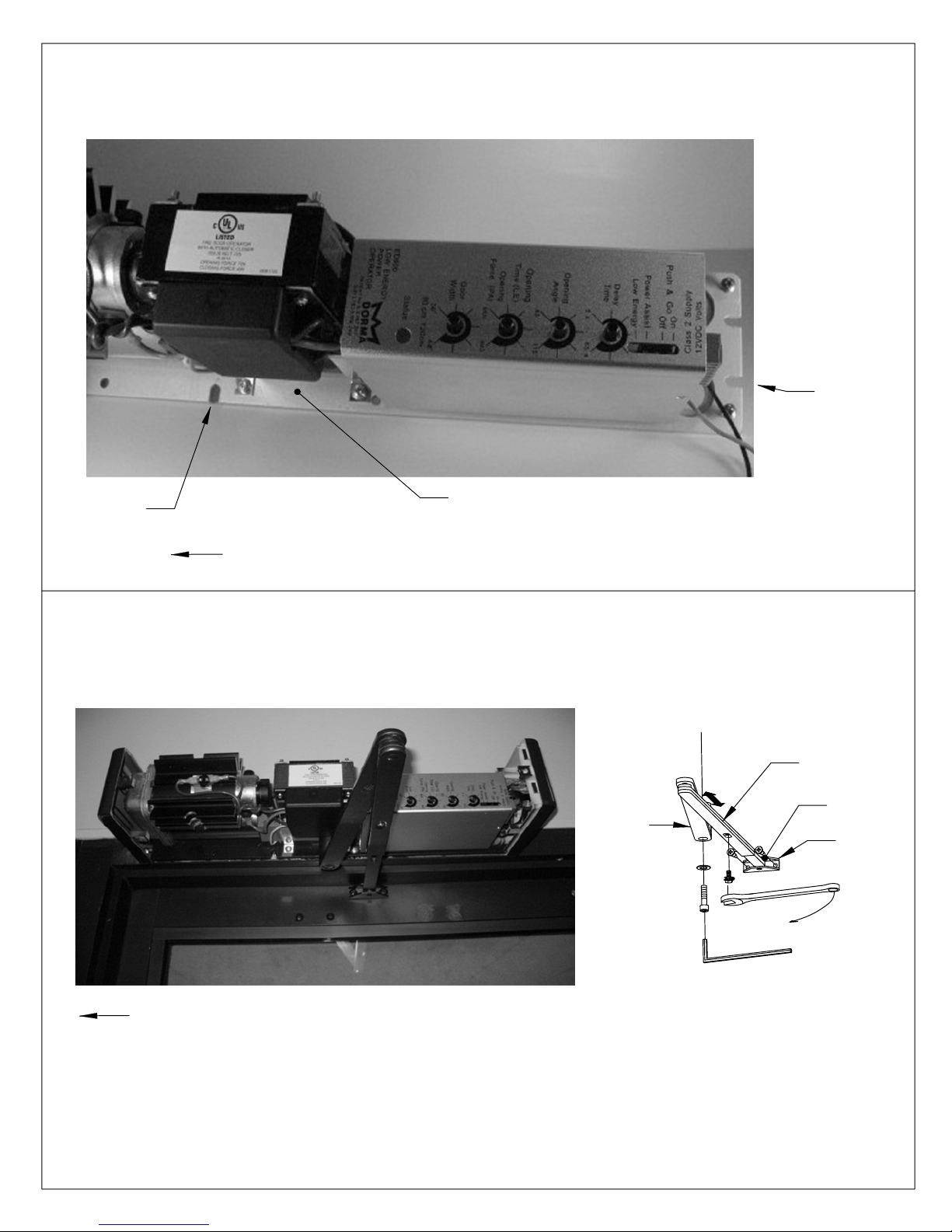
Initially install screws for slots "A" as pictured, allowing 5/16" between the screw head and the frame.
Align the slots in the mounting plate with the screws. Slide the mounting plate over the screw and hold
the unit in place until the balance of the screws are installed. Tighten all screws securely.
SLOT "A"
SLOT "A"
MOUNTING
PLATE
HINGE SIDE OF DOOR
Orient arm as shown. Attach arm shoe to door. Place wrench on top pinion shaft and rotate pinion
slightly toward latch edge of door. Slide main arm over bottom pinion shaft. Fasten securely with
pinion screw and lock washer provided. Loosen screw in connecting arm so arm slides freely.
Adjust connecting arm length so rod and connecting arm are 90° to door. Re-tighten screw.
MAIN
ARM
LOCK WASHER
PINION SCREW
CONNECTING
ARM
ROD
ARM SHOE
HINGE SIDE OF DOOR
6 mm HEX KEY
08102710 05/07ED800-7
Page 8
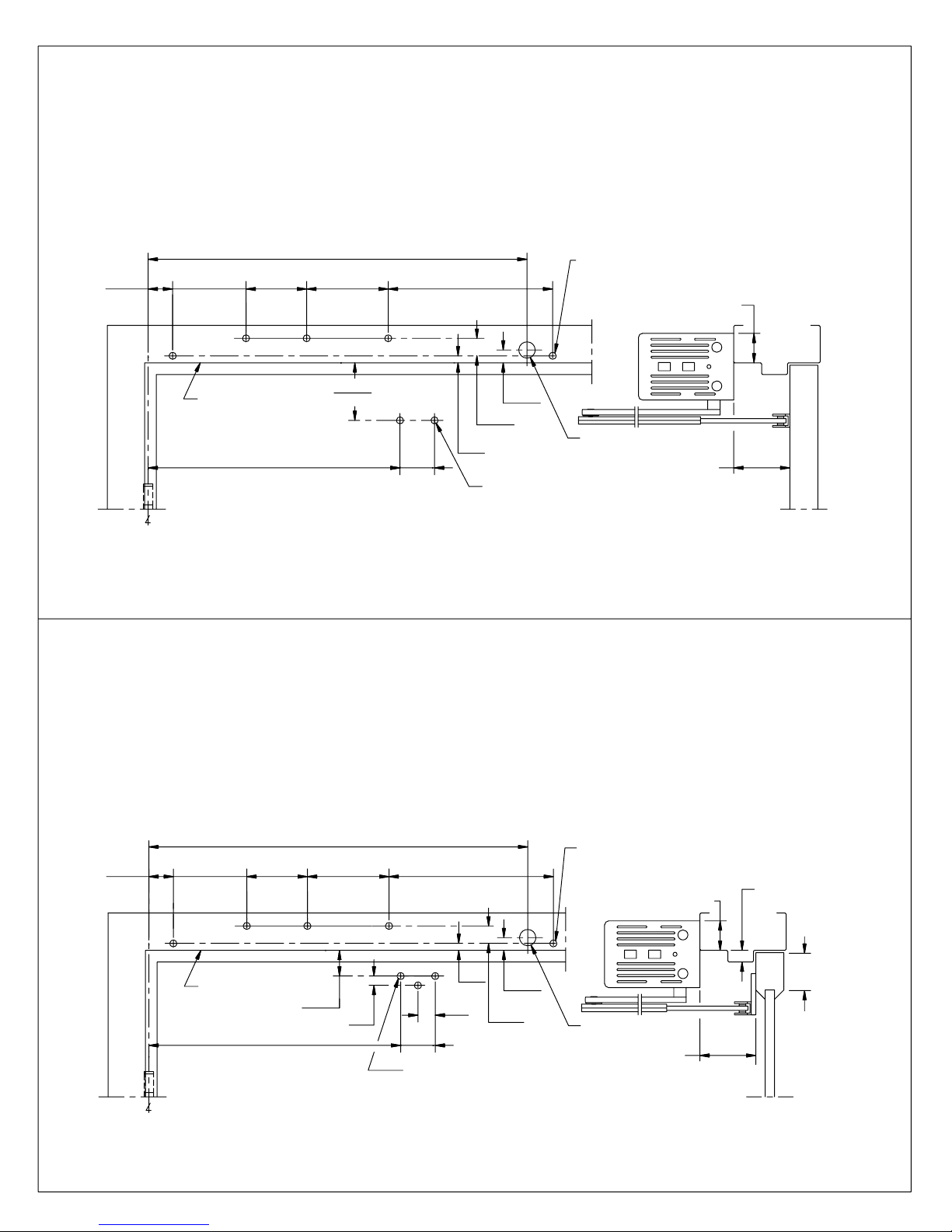
ED 800J X DROP - TOP JAMB DROP INSTALLATION TEMPLATE & MOUNTING
INSTRUCTIONS
Prepare door and frame according to template.
NOTES:
1. DO NOT SCALE DRAWING.
2. DIMENSIONS ARE IN INCHES/(MM).
3. LEFT HAND DOOR SHOWN.
4. CAUTION: SEX NUTS ARE REQUIRED FOR
ATTACHMENT OF COMPONENTS TO UNREINFORCED
DOORS AND TO WOOD OR PLASTIC FACED
COMPOSITE TYPE FIRE DOORS, UNLESS AN
ALTERNATIVE METHOD IS IDENTIFIED IN THE
INDIVIDUAL DOOR MANUFACTURER'S LISTINGS.
1-5/16
(33)
3-15/16
(100)
3-1/4
(83)
20-11/16
(525)
4-3/8
(111)
5. SEE CATALOG FOR ARM NUMBER
FOR NON STANDARD REVEALS.
6. MAXIMUM OPENING ANGLE 115°
7. DOORS AND FRAMES MUST BE PROPERLY
REINFORCED.
8. AUXILIARY STOP, (BY OTHERS) ARE REQUIRED AT 115° FOR
INSTALLATIONS WHERE DOOR CAN OPEN FURTHER THEN 115°
FOR 1/4-20 MACHINE SCREWS USE No.7(0.201") DRILL & TAP
8-13/16
(224)
FOR No. 14 WOOD SCREWS USE 5/32" DRILL
FIVE (5) HOLES IN FRAME FOR PLATE
MINIMUM TO CEILING 1-3/4"
4-1/4
BOTTOM OF FRAME
12-5/8
(321)
OF 4-1/2" WIDE HINGE, 3/4" OFFSET PIVOT
C
ED800J X DROP
TOP JAMB DROP INSTALLATION - LOW CEILING CLEARANCE
(PUSH SIDE MOUNT)
(108)
1-3/4
(44)
11/16
(17)
15/16
(24)
3/8
(10)
FOR 1/4-20 MACHINE SCREWS USE No.7 DRILL
FOR No.14 WOOD SCREWS USE 5/32" DRILL
FOR SEX NUTS USE 3/8" DRILL
TWO (2) HOLES IN DOOR FOR ARM SHOE
7/8" DIA. HOLE FOR
WIRE ACCESS
2" TO 6" STD.
REVEAL
SEE
NOTE
# 5
ED800-2 Rev.08/04
ED 800J X DROP X 830 - TOP JAMB DROP INSTALLATION WITH 830 ARM SHOE DROP
PLATE TEMPLATE & MOUNTING INSTRUCTIONS
Prepare door and frame according to template.
NOTES:
1. DO NOT SCALE DRAWING.
2. DIMENSIONS ARE IN INCHES/(MM). 5. SEE CATALOG FOR ARM NUMBER
3. LEFT HAND DOOR SHOWN.
4. CAUTION: SEX NUTS ARE REQUIRED FOR
ATTACHMENT OF COMPONENTS TO UNREINFORCED
DOORS AND TO WOOD OR PLASTIC FACED
COMPOSITE TYPE FIRE DOORS, UNLESS AN
ALTERNATIVE METHOD IS IDENTIFIED IN THE
INDIVIDUAL DOOR MANUFACTURER'S LISTINGS.
20-11/16
(525)
1-5/16
(33)
3-15/16
(100)
3-1/4
(83)
4-3/8
(111)
FOR NON STANDARD REVEALS.
6. MAXIMUM OPENING ANGLE 115°
7. DOORS AND FRAMES MUST BE PROPERLY
REINFORCED.
8. AUXILIARY STOP, (BY OTHERS) ARE REQUIRED AT 115° FOR
INSTALLATIONS WHERE DOOR CAN OPEN FURTHER THEN 115°
FOR 1/4-20 MACHINE SCREWS USE No.7(0.201") DRILL & TAP
8-13/16
(224)
FOR No. 14 WOOD SCREWS USE 5/32" DRILL
FIVE (5) HOLES IN FRAME FOR PLATE
MINIMUM TO CEILING 1-3/4"
3/4" MAX.
BOTTOM OF FRAME
12-5/8
(321)
OF 4-1/2" WIDE HINGE, 3/4" OFFSET PIVOT
C
ED800J X DROP X 830 ARM SHOE DROP PLATE
TOP JAMB DROP INSTALLATION - LOW CEILING CLEARANCE / NARROW TOP RAIL
(PUSH SIDE MOUNT)
1-3/8
(35)
1/2
(13)
3/8
11/16
(10)
7/8
(22)
1-3/4
(44)
FOR 1/4-20 MACHINE SCREWS USE No.7 DRILL
FOR No.14 WOOD SCREWS USE 5/32" DRILL
FOR SEX NUTS USE 3/8" DRILL
THREE (3) HOLES IN DOOR FOR PLATE
15/16
(24)
(17)
7/8" DIA. HOLE FOR
WIRE ACCESS
2" TO 6" STD.
REVEAL
SEE
NOTE
# 5
ED800-4 Rev.08/04
ED800-8 08102710 05/07
2" MIN.
TOP RAIL
Page 9
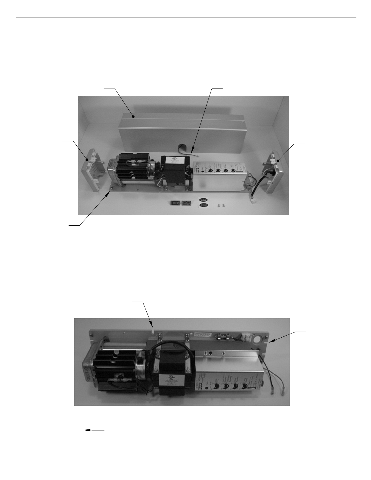
Remove two (2) cover screws and cover. Disconnect cover ground wire at base plate. Loosen,
but do not remove end cap screws and slide end caps off.
Note:
Re-install end caps, cover ground wire and cover after installation is complete. Push-in emblems
or logo decals can be applied to hide cover screws if needed.
GROUND WIRE FOR COVER
END CAP
WITH
SWITCHES
END CAP
END CAP
SCREW
COVER
(LEFT HAND MOUNT SHOWN)
Initially install screws for slots "A" as pictured, allowing 5/16" between the screw head and the frame.
Align the slots in the mounting plate with the screws. Slide the mounting plate over the screw and hold
the unit in place until the balance of the screws are installed. Tighten all screws securely.
SLOT "A"
HINGE SIDE OF DOOR
ED800-9
SLOT "A"
08102710 05/07
Page 10
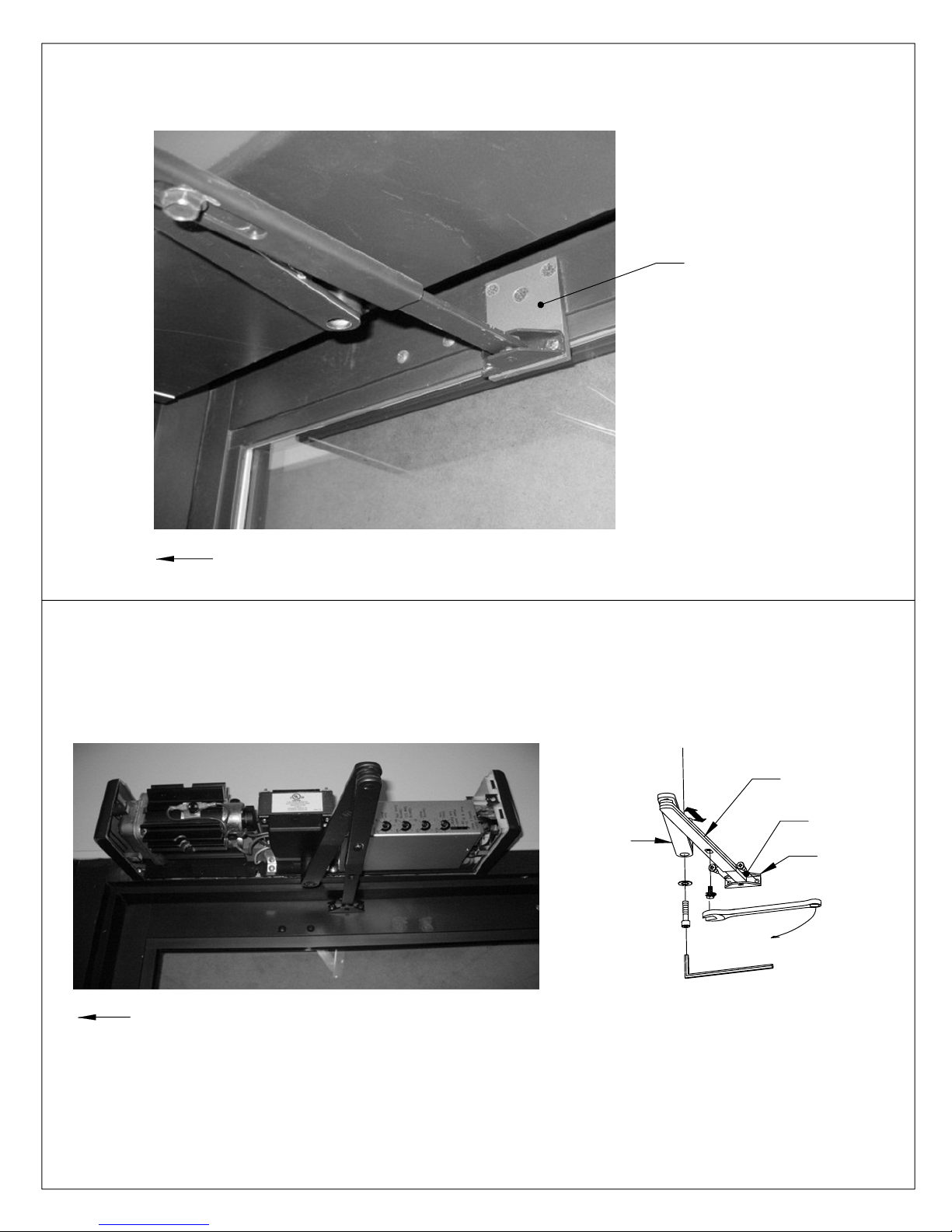
If required, attach 830 arm shoe drop plate to top rail with three screws provided.
830 DROP PLATE
HINGE SIDE OF DOOR
Orient arm as shown. Attach arm shoe to door or 830 arm shoe drop plate. Place wrench on top
pinion shaft and rotate pinion slightly toward latch edge of door. Slide main arm over bottom pinion
shaft. Fasten securely with pinion screw and lock washer provided. Loosen screw in connecting
arm so arm slides freely. Adjust connecting arm length so rod and connecting arm are 90° to door.
Re-tighten screw.
MAIN
ARM
LOCK WASHER
PINION SCREW
6 mm HEX KEY
CONNECTING
ARM
ROD
ARM SHOE
HINGE SIDE OF DOOR
08102710 05/07ED800-10
Page 11
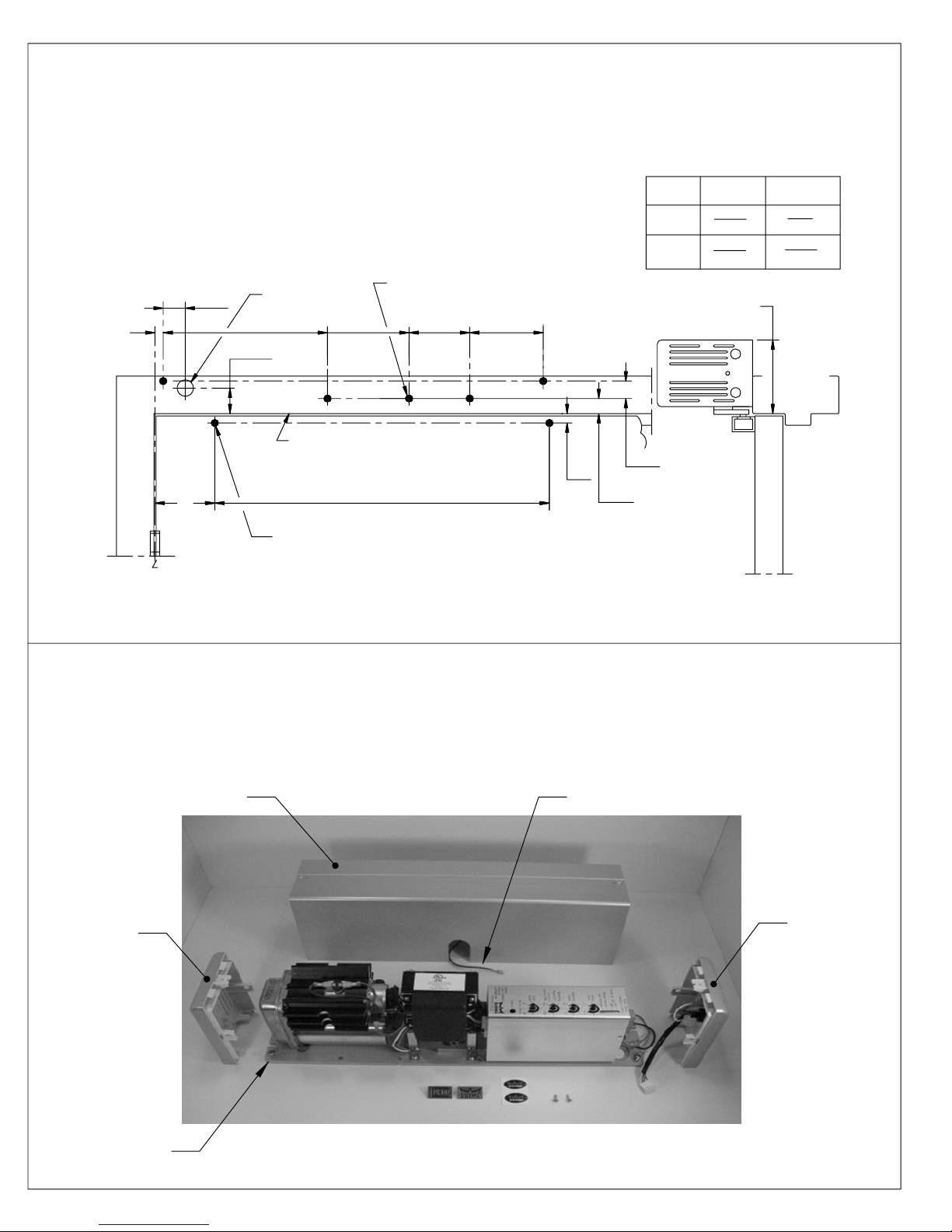
ED 800T - TRACK INSTALLATION TEMPLATE & MOUNTING INSTRUCTIONS
Prepare door and frame according to template.
NOTES:
1. DO NOT SCALE DRAWING.
2. DIMENSIONS ARE IN INCHES/(MM).
3. RIGHT HAND DOOR SHOWN.
4. CAUTION: SEX NUTS ARE REQUIRED FOR
ATTACHMENT OF COMPONENTS TO UNREINFORCED
DOORS AND TO WOOD OR PLASTIC FACED
COMPOSITE TYPE FIRE DOORS, UNLESS AN
ALTERNATIVE METHOD IS IDENTIFIED IN THE
INDIVIDUAL DOOR MANUFACTURER'S LISTINGS.
1
(25)
"A"
"B"
7/8" DIA. HOLE FOR
WIRE ACCESS
8-13/16
(224)
1-7/16
(37)
4-3/8
BOTTOM OF FRAME
(111)
5. MAXIMUM OPENING ANGLE 115°.
6. DOORS AND FRAMES MUST BE PROPERLY REINFORCED.
7. AUXILIARY STOP, (BY OTHERS) ARE REQUIRED AT 115° FOR
INSTALLATIONS WHERE DOOR CAN OPEN FURTHER THEN 115°
FOR 1/4-20 MACHINE SCREWS USE No.7 (0.201") DRILL
FOR No. 14 WOOD SCREWS USE 5/32" DRILL
FIVE (5) HOLES IN FRAME FOR PLATE
3-1/4
(83)
23-1/2
(597)
3-15/16
(100)
1/2
(13)
MINIMUM TO CEILING 4-5/8"
13/16
(21)
15/16
(24)
DIM. "A"
DIM. "B"
4-1/2"
WIDE HINGE
7/16" 1"
(11) (25)
4-5/16"
(106)
3/4" OFFSET
PIVOT
4-7/8"
(124)
FOR 1/4-20 MACHINE SCREWS USE No.7 (0.201") DRILL
FOR No.14 WOOD SCREWS USE 5/32" DRILL
OF HINGE
C
FOR SEX NUTS USE 3/8" DRILL
TWO (2) HOLES IN DOOR FOR TRACK
ED800-3 Rev.08/04
Remove two (2) cover screws and cover. Disconnect cover ground wire at base plate. Loosen,
but do not remove end cap screws and slide end caps off.
Note:
Re-install end caps, cover ground wire and cover after installation is complete. Push-in emblems
or logo decals can be applied to hide cover screws if needed.
COVER
END CAP
GROUND WIRE FOR COVER
END CAP
WITH
SWITCHES
END CAP
SCREW
(LEFT HAND MOUNT SHOWN)
ED800-11
08102710 05/07
Page 12
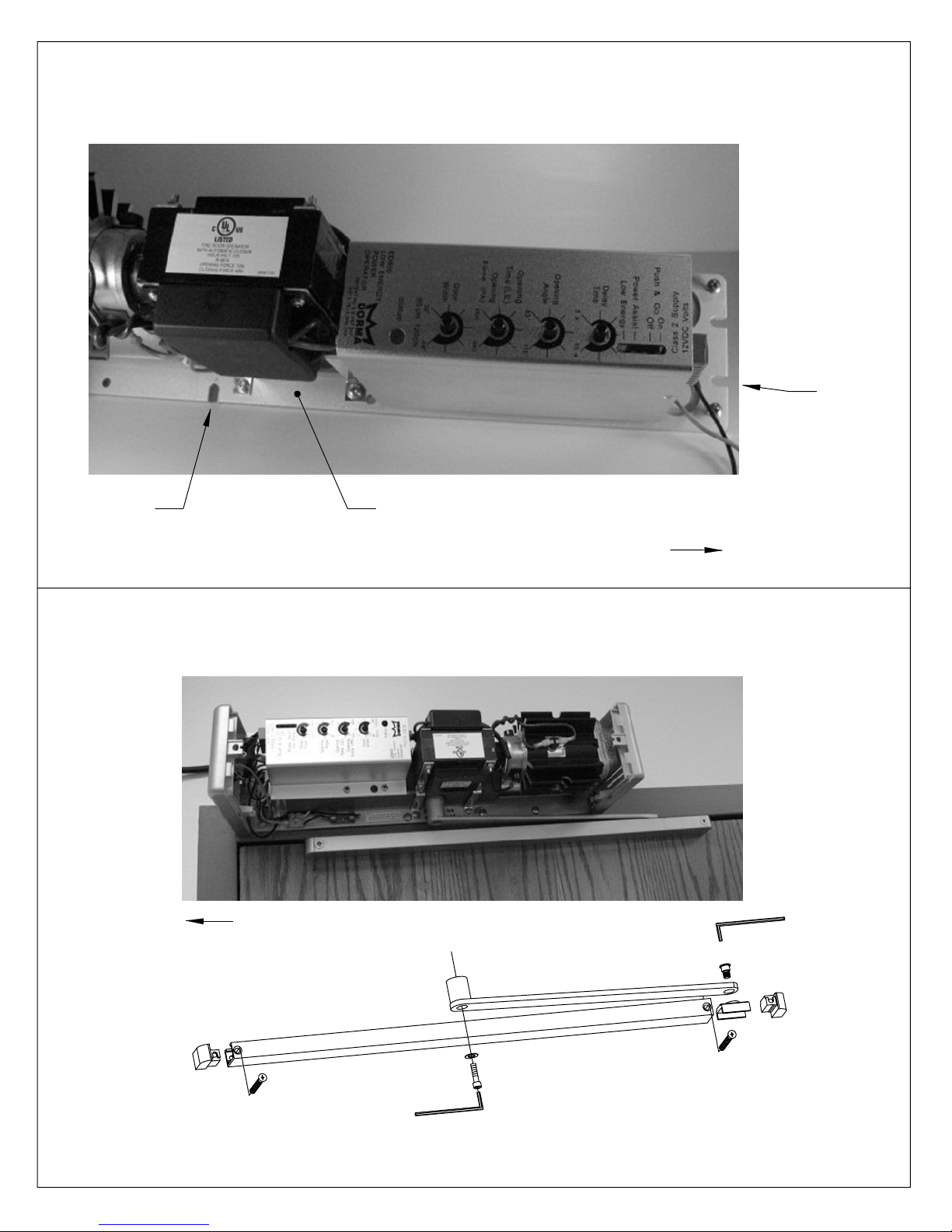
Initially install screws for slots "A" as pictured, allowing 5/16" between the screw head and the frame.
Align the slots in the mounting plate with the screws. Slide the mounting plate over the screw and hold
the unit in place until the balance of the screws are installed. Tighten all screws securely.
SLOT "A"
SLOT "A" MOUNTING PLATE
HINGE SIDE OF DOOR
Insert slide shoe and end blocks into track and attach track to door. Attach arm to slide shoe using
screw provided. Place wrench on top pinion shaft and rotate 45° towards hinge edge of door. Slide
arm over bottom pinion shaft. Fasten securely with pinion screw and lock washer provided.
HINGE SIDE OF DOOR
SLIDE SHOE SCREW
5 mm HEX KEY
END BLOCK
END BLOCK
LOCK WASHER
PINION SCREW
6 mm HEX KEY
08102710 05/07ED800-12
Page 13
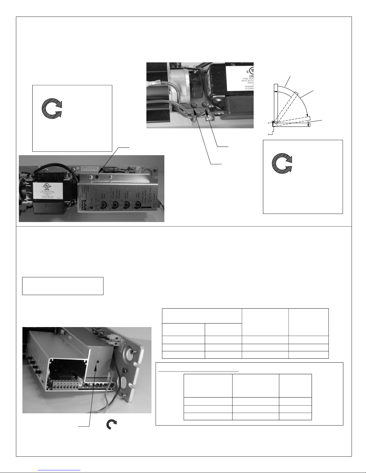
VALVE ADJUSTMENTS
Adjust sweep, latch and backcheck valves. Closing time from 90° to 10° (sweep range) should
take at least 3 seconds. Closing time from 10° to fully closed (latch range) should take at least 1.5
seconds. Backcheck intensity should be adjusted to ensure that door is under control during the
opening cycle
BACKCHECK RANGE
CAUTION: DO NOT REMOVE VALVES.
INCREASE
DECREASE
SWEEP
RANGE
LATCH
RANGE
BACKCHECK
INTENSITY
SPRING POWER ADJUSTMENT
Adjust spring tension according to the chart below. The ED 800 is shipped from the factory as
a size 3. The spring power can be increased to a size 5. Clockwise turns increase spring power.
Do not decrease spring power from factory setting.
CRITICAL
Spring tension must be adjusted to ensure that door will close
and latch consistently.
BACKCHECK VALVE
SWEEP
VALVE
LATCH
VALVE
DECREASE
INCREASE
SWEEP & LATCH
SPEED
adjust with
5 mm hex key
INCREASE
DOOR WIDTH
EXTERIOR
3'-0"
3'-6"
ULC LABELED UNITS ONLY - ADJUST ACCORDING TO CHART
MAX.
DOOR
WEIGHT (LBS.)
INTERIOR
3'-0"
3'-6"
4'-0"
125
150
200
FULL TURNS
OF SPRING
ADJUSTING
0
6
9
FULL TURNS
OF SPRING
ADJUSTING
0
6
9
SPRING
SIZE
3
4
5
SPRING
SIZE
3
4
5
08102710 05/07ED800-13
Page 14
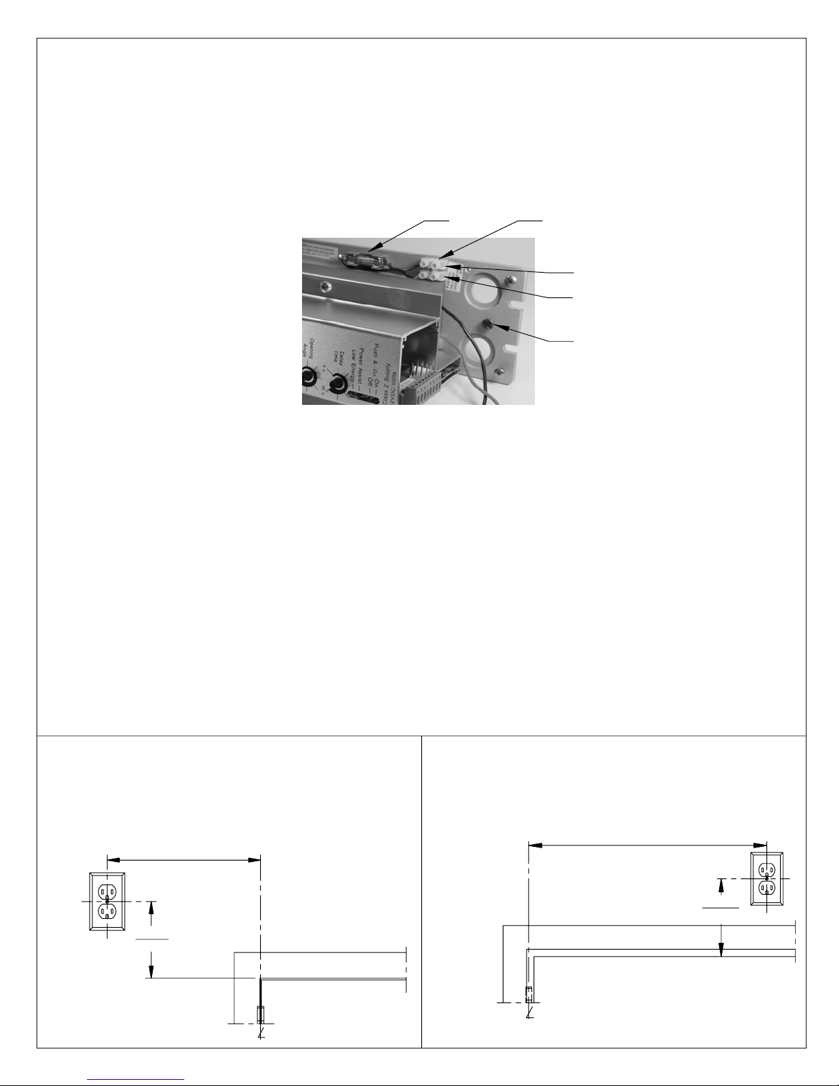
MAIN POWER CONNECTION
Connect the 120 volt AC power supply wires to the ED 800 terminal block. Connect the ground
wire to the green ground screw on the mounting plate. Observe all local electrical codes when
performing connections.
The incoming wire size is to be 14 AWG. The maximum power consumption of the ED 800 is 2
amps.
WARNING: DISCONNECT POWER WHILE MAKING CONNECTIONS.
FUSE TERMINAL BLOCK
L1 (BLACK)
N (WHITE)
GROUND
POWER CORD OPTION (refer to Installation Instructions 08076325)
The ED800 is available with an optional power cord which allows the unit to be plugged directly
into a standard receptacle. If power cord is being added as a field option, refer to instructions
packaged with power cord. A grounding-type 120 volt receptacle rated for a minimum of 15 amps.
is required and should be located at the approximate location shown. When considering the
amount of units to be supplied by one circuit, remember the power consumption is 2 amps. per
unit.
When routing the power cord to the receptacle, do not run through doorways, window openings,
walls, ceilings, floors, or the like. Do not attach or otherwise secure the power cord to the building
structure, and do not conceal the power cord behind walls.
WARNING: DO NOT ALLOW THE POWER CORD TO BECOME ENTRAPPED IN THE MOVING
PARTS OF THE ED 800 OR THE DOOR AND THE FRAME.
If the local codes require permanent wiring to be employed, refer to Main Power Connection
section.
Track Installations
Top Jamb
&
Top Jamb Drop Installations
32
10
(254)
6
(152)
(813)
6
(152)
HINGE
C
HINGE
C
Push Side of DoorPull Side of Door
08102710 05/07ED800-14
Page 15
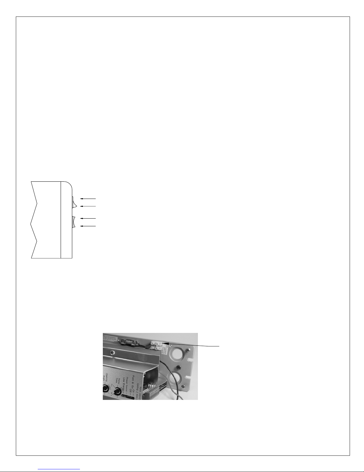
FUSE
The ED 800 is protected by a 3 amp type AGC size 1/4" x 1 1/4" fuse. Replace only with an
identical fuse.
WARNING: DISCONNECT POWER TO THE ED 800 WHEN REPLACING THE FUSE.
ON/OFF SWITCH
The ED 800 is equipped with an on/off switch which is located in the end cap closest to the control
module. The switch must be in the "on" position for any powered function. It is recommended that
the switch be in the "off" position after hours or during extended idle periods.
HOLD OPEN/CLOSE SWITCH
The ED 800 is equipped with a standard "hold open" feature. To activate, momentarily depress the
switch towards "hold open". The door will open and remain in the open position for approximately 5
minutes. After that period of time, the door will then close and the unit will be ready for normal
operation. To close the door at any time, depress the switch towards "close". This will override the
time delay and close the door immediately.
NOTE: Hold Open/Close Switch must be plugged into control module to enable operator.
ON "1"
OFF "0"
HOLD OPEN
CLOSE
REMOTE SWITCH OPTION (refer to Installation Instructions 08105680)
If the ED 800 is ordered with the RS - Remote Switch option, the On/Off switch and the Hold
Open/Close switch are deleted. This is recommended for applications where the switches may be
subjected to tampering. In this application, a remote switch must be provided (by others) in the
incoming power supply. This switch must be wired in accordance to The National Electrical Code.
L1 with
SPST SWITCH
RATED @
3amp @ 120 VOLTS MIN.
(BY OTHERS)
FIRE DOOR WIRING
When the ED 800 is installed on a fire door, the main power to the unit must be supplied through a
set of contacts in a UL listed fire alarm panel. The contacts are to be closed under normal
(stand-by) conditions providing power to the unit. Under alarm conditions, the contacts must open,
cutting power to the unit, causing the ED 800 to operate as a manual door closer.
08102710 05/07ED800-15
Page 16
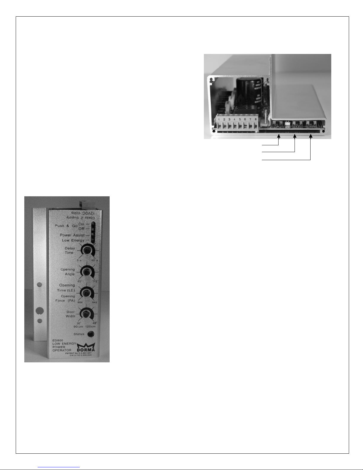
POWER ADJUSTMENTS
NOTE: Before making any power adjustments, the ED 800 unit must be properly installed on
the door and frame, the arm must be adjusted and the spring tension set.
PUSH/PULL SWITCH
Determine that the Push/Pull switch is set properly.
Push is required for all top jamb applications. Pull is
required for all track applications. (See page 18 for
switch location)
LATCH DELAY ON/OFF SWITCH
When turned "ON" this switch delays the function of
the operator by 1/2 second to allow time for a strike to
operate. (See pages 5 or 25)
LATCH DELAY SWITCH (OFF/ON)
MOUNT STYLE SWITCH (PUSH/PULL)
CLOSING OBSTACLE SWITCH (OFF/ON)
LOW ENERGY FUNCTION
1. Adjust the "Power Assist/Low Energy" slide switch to the "Low
Energy" position.
2. Adjust the "Door Width" potentiometer to match the approximate
door width. Doors must be between 36 and 48 inches wide for
optimum operation.
3. Adjust the "Opening Time(LE)" potentiometer to obtain the
desired door opening time. "MIN" is the least amount of opening
time (fastest door speed), and "MAX" is the greatest amount of
opening time (slowest door speed).
4. Adjust the "Opening Angle" potentiometer to obtain the desired
angle of opening (Hold Open Position). This is adjustable from 85°
to 115°. This is a "live" adjustment when the door is in the hold
open position
5. Adjust the "Delay Time" potentiometer to obtain the desired
amount of time the door will remain at the hold open position. This
is adjustable from 5 to 60 seconds. The delay time will commence
when the door reaches the hold open position, or when it last
receives an actuation input, whichever occurs later.
6. Adjust the "Push & Go" slide switch as required. When in the
"on" position, a door movement of one inch will activate the unit. If
the user opens the door briskly beyond 45° the Push & Go feature
will abort. This is to conserve heating and air conditioning energy
and to prevent the unit from operating needlessly. When in the "off"
position, the unit must be activated externally.
Refer to the Functional Detail in the General Information section for a complete description of the
operation of the ED 800 in Low Energy Function.
ED800-16 08102710 05/07
Page 17
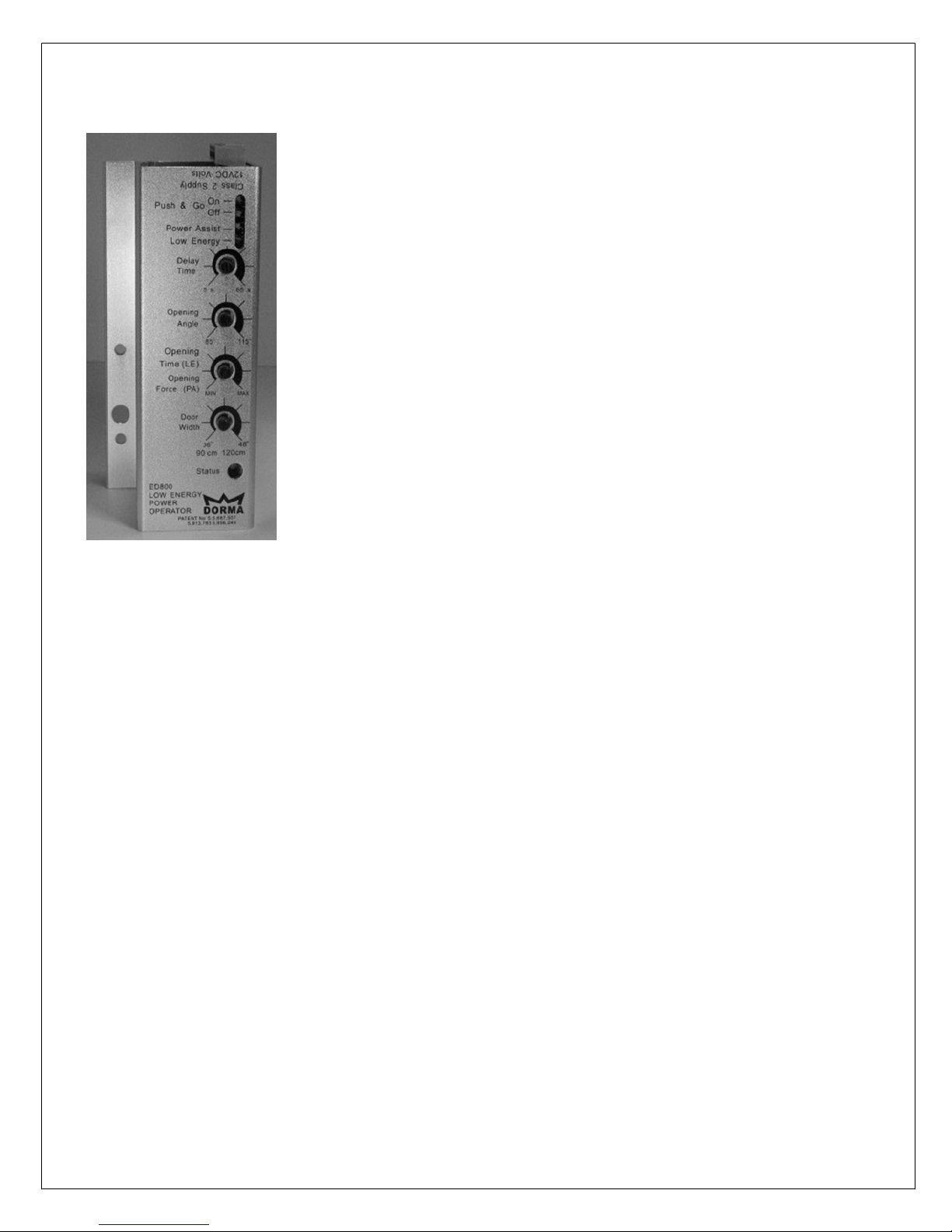
POWER ASSIST FUNCTION
1. Adjust the "Power Assist/Low Energy" slide switch to the "Power
Assist" position.
2. Adjust the "Door Width" potentiometer to match the approximate
door width. Doors must be between 36 and 48 inches wide for
optimum operation.
3. Adjust the "Opening Force(PA)" potentiometer to obtain the
amount of opening force desired. "MIN" is the least amount of
force required to open the door (approximately 1.5 pounds of force),
and "MAX" is the greatest amount of force required to open the
door (approximately 5 pounds of force).
4. Adjust the "Opening Angle" potentiometer to obtain the
maximum angle of opening to which the unit will assist.
5. Adjust the "Delay Time" potentiometer to obtain the desired
amount of time the door will remain in the Power Assist function
once activated. This is adjustable from 5 to 60 seconds. The delay
time will commence upon activation or when there is no longer any
door movement, whichever occurs later.
6. Adjust the "Push & Go" slide switch as required. When in the
"on" position, a door movement of one inch will activate the unit. If
the user opens the door briskly beyond 45° the Push & Go feature
will abort. This is to conserve heating and air conditioning energy
and to prevent the unit from operating needlessly. When in the "off"
position, the unit must be activated externally.
Refer to the Functional Detail in the General Information section for a complete description
of the ED 800 in Power Assist Function.
LATCHED DOOR
If the ED 800 is to be installed on a door which is required to be latched, it is recommended that an
electric strike release or electric latch retraction device be installed. When the ED 800 is installed
on a door with an exit device, the device should be dogged during hours when the ED 800 is turned
on.
If it is not possible to release the strike or retract the latch, the ED 800 must be activated by only
the Push & Go feature. Also, the latch must be manually held retracted when the unit is initially
turned on. This is because the ED 800 performs a "learn cycle" when it is first energized. Part of
the learn cycle requires that the door be opened a few degrees to obtain information about the
amount of force required to open that particular door. If the door is latched during the learn cycle,
the ED 800 will default to the power requirements of a typical 36" wide interior door.
If this is not satisfactory, simply turn the unit off, wait approximately 30 seconds, then turn the unit
back on while holding the latch retracted until the learn cycle is completed.
ED800-17 08102710 05/07
Page 18
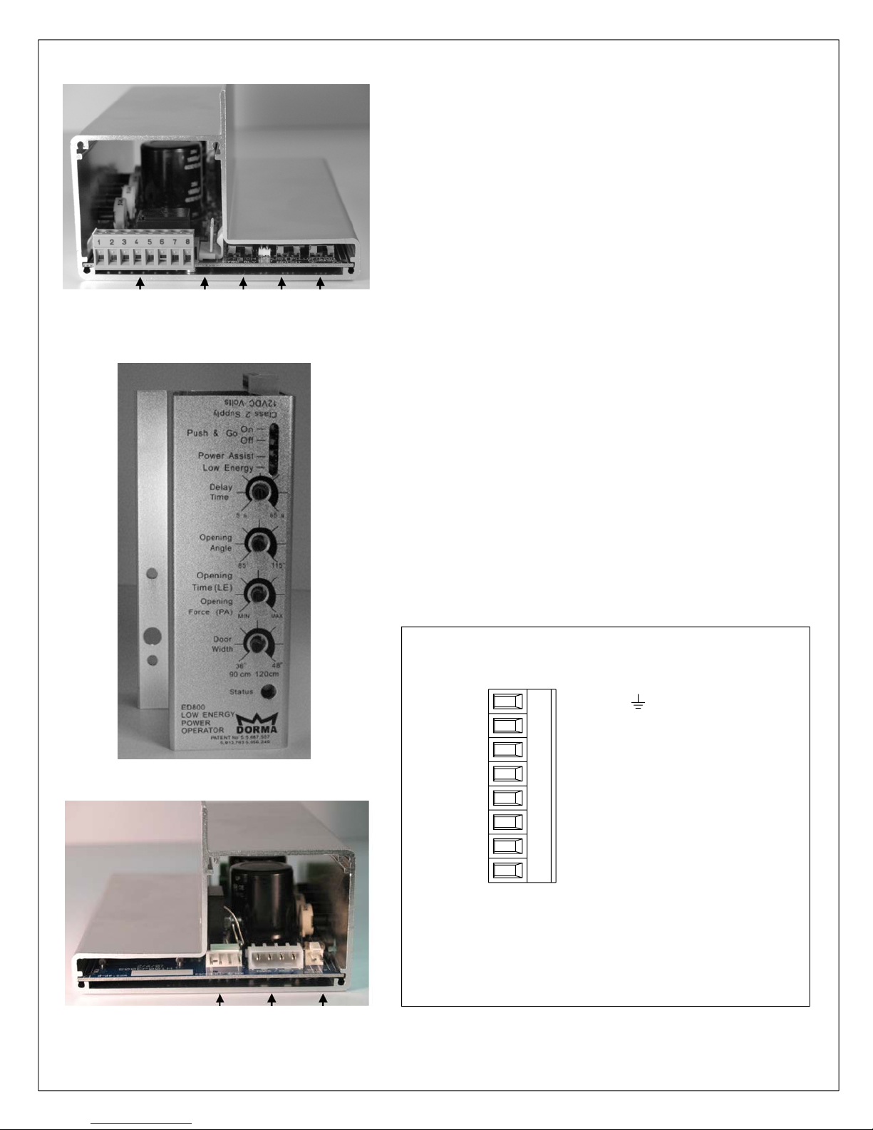
ED800 Controller Module Diagram
External Connector (See below)
Encoder Connection
Transformer/Motor Connection
Battery (Factory use only)
Hold Open Switch Connection
Closing Obstacle Switch (Off/On)
Mount Style Switch (Push/Pull)
Latch Delay Switch (Off/On)
External Connector
GROUND
2
+12VDC
31
OPEN TRIGGER
4
BUSY SWING (SAFETY)
5
VESTIBULE
6
NO
7
C
8
NC
NOTE: Terminal can be removed from control
module to simplify installation of wires. The
maximum recommended wire size is 18 AWG.
ED800-18 08102710 05/07
Page 19
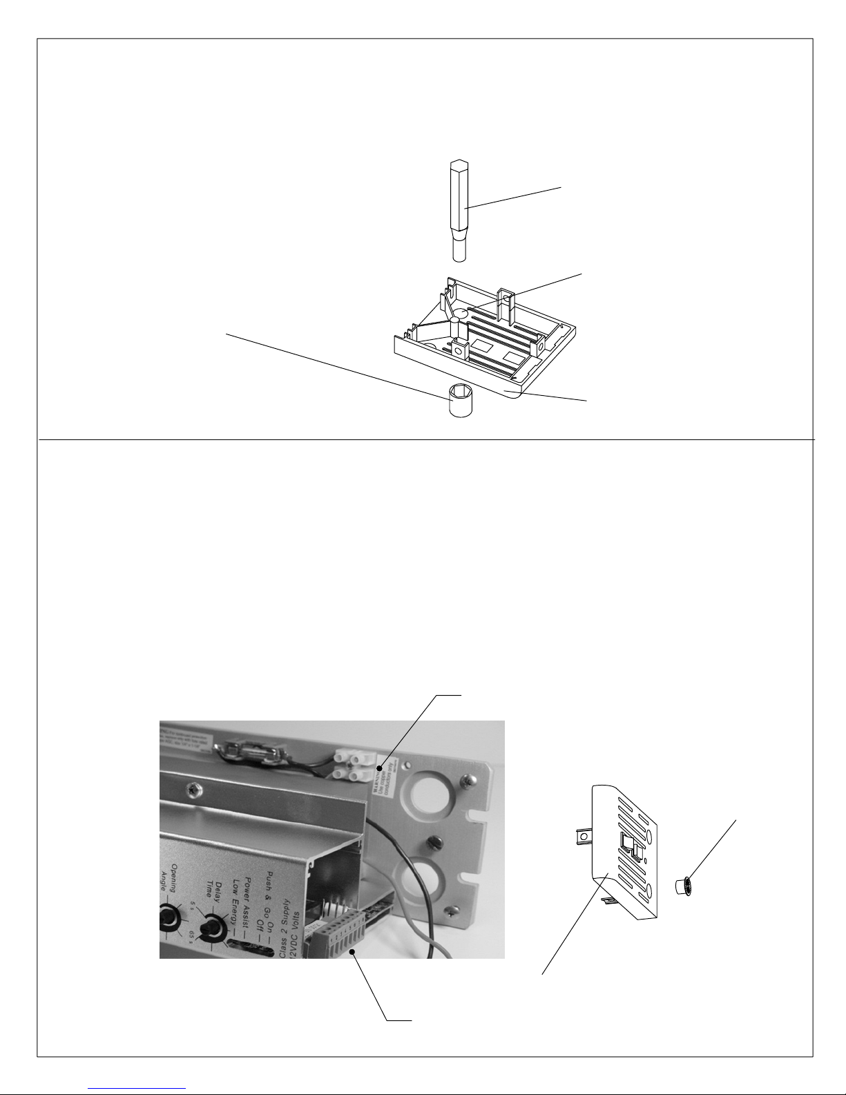
ACCESSORY WIRE ROUTING
Remove knockout with a 1/2" diameter punch and hammer. Back side of end cap must be
supported to prevent damage to the end cap.
1/2" DIA. PUNCH
KNOCKOUT
OVERSIZE SOCKET
AS RECEIVER
END CAP
Insert bushing into end cap.
Feed accessory wires through bushing in end cap. Connect wires as required to external connector.
Note: Accessory wires must be isolated from 120V incoming power
120V INCOMING FEED WIRED HERE
BUSHING
END CAP
EXTERNAL CONNECTOR FOR ACCESSORY WIRES
08102710 05/07ED800-19
Page 20
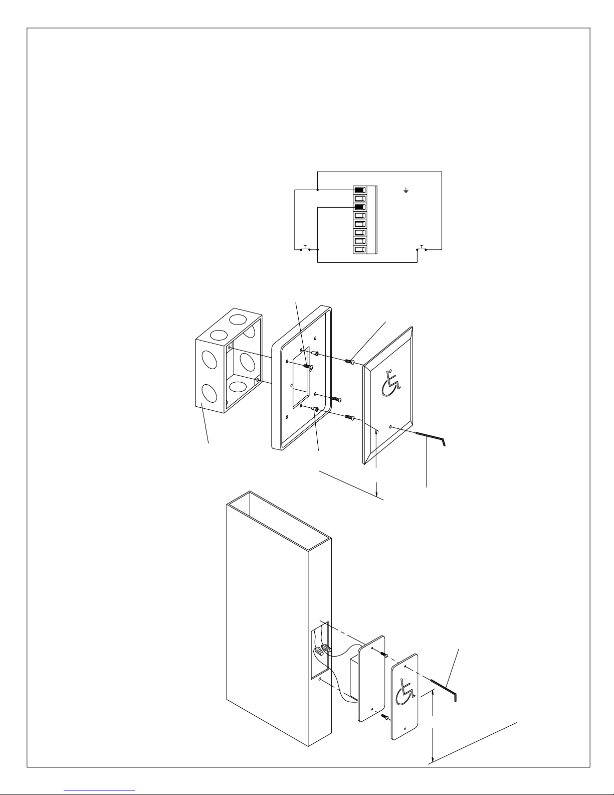
OPEN TRIGGER
WS-1 Wall Switch
FS-1 Frame Switch
The open trigger is created by providing a dry, normally open circuit , which is momentarily closed
to signal the ED 800. Contact is made between "OPEN TRIGGER" and "GROUND".
Typical Wall Switch or Frame switch wiring diagram.
GROUND
+12VDC
321
OPEN TRIGGER
4
BUSY SWING (SAFETY)
5
VESTIBULE
NO
76
C
ED 800
8
NC
Outside Switch
WS-1 WALL SWITCH
When considering the location
Inside Switch
of the 800 WS-1 Wall Switch,
sufficient distance should be
4x4 box mounting screws
allowed between the switch
and the door, to allow for the
6 x 32 wall switch mounting screws
door to open.
4x4 or 2x4 Junction box
(by others)
FS-1 FRAME SWITCH
The FS-1 Frame Switch is
designed to be installed in a
metal door frame with a
minimum width of 1 3/4".
NOTE: Generally, a
junction box is not used
with this type of switch
6-32 screw plastic inserts
42" APPROXIMATE CL
FINISHED
FLOOR
Tighten screws through holes in
cover plate with 3/32" hex key
Tighten screws through holes in
cover plate with 5/64" hex key
42" APPROXIMATE CL
FINISHED FLOOR
ED800-20 08102710 05/07
Page 21
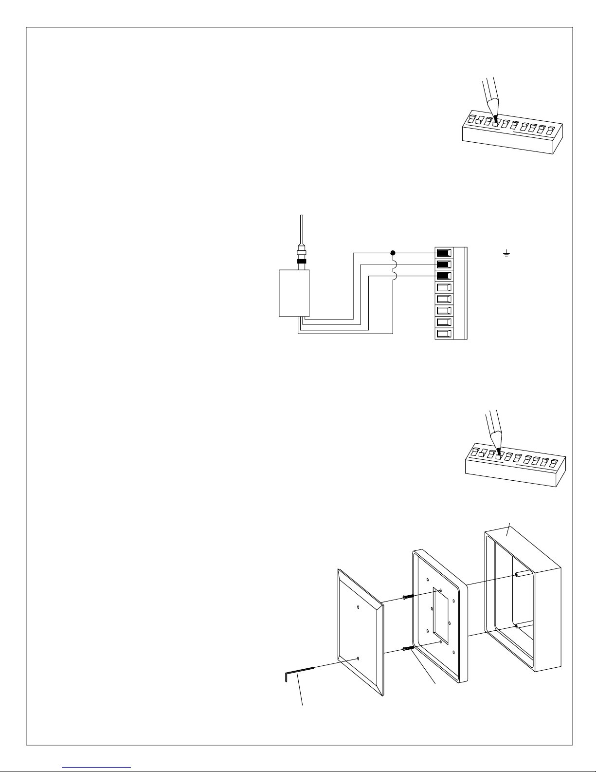
800RFR Radio Frequency Receiver
The 800RFR RF Receiver can be used on applications where it is not practical to run
wires from a switch to the ED 800 unit.
A code must be selected to insure the receiver is only activated by the intended
transmitter(s). This is determined by the positions of the 10 small switches numbered
1 through 10 located on the receiver board. To gain access to the switch, remove the
top section of the case. Any combination of on (closed) or off (open) positions can be
selected by using a small screwdriver or ball point pen. It is strongly recommended
1
CODE SWITCH
2
3
4
5
o
p
e
n
6
that the following codes be avoided: all on; all off; 2, 4, 6, 8, 10 on; or 1, 3, 5, 7, 9, on.
These codes are frequently used and create the possibility of false operation. After
selecting the code be sure it is recorded so that it may be duplicated in any transmitter
intended to operate the door.
Connect wires according to following
diagram.
Install antenna by threading it on
the connector. Locate receiver in
close proximity to the ED 800 unit.
Position antenna so that it is clear
of metal structures. Anchor the
receiver permanently.
800RFR
RECEIVER
NOTE: Be sure receiver unit is kept away from direct moisture.
After installation is complete, check for proper operation. The transmitter should provide reliable
operation from a distance of about 50 feet, however the environment and location of both transmitter and
receiver will affect range.
BLACK
RED
GRAY
GRAY
GROUND
2
+12VDC
31
OPEN TRIGGER
4
BUSY SWING (SAFETY)
5
VESTIBULE
6
NO
7
C
8
NC
7
8
9
1
0
WS/RFT-1Wall Switch
The WS/RFT-1 wall switch with radio frequency transmitter is used in conjunction
with the 800RFR radio frequency receiver. The wall switch transmitter must be located
within a distance of 50 feet from the receiver. The WS/RFT-1 is suitable for outdoor
use, however it must not be exposed to direct moisture. Anchor the backplate of the
wall switch securely to the mounting surface at a height approximately 42" above the
finished floor.
Anchor backplate securely to wall.
Select the code for the transmitter. The code must
be identical to the code for the receiver which is
intended to be signalled. Refer to code selection
for 800RFR Radio Frequency Receiver. Connect the 9
volt battery at this time.
The replacement battery is 9 volt NEDA 1604
(Eveready 216 or equivalent).
6 - 32 Wall switch mounting screw.
1
2
3
4
CODE SWITCH
5
6
7
8
9
1
o
p
e
n
0
Tighten screws through holes in cover
plate with 5/64" hex key.
ED800-21 08102710 05/07
NOTE:
Flush Mount Assembly Kit also available
Page 22
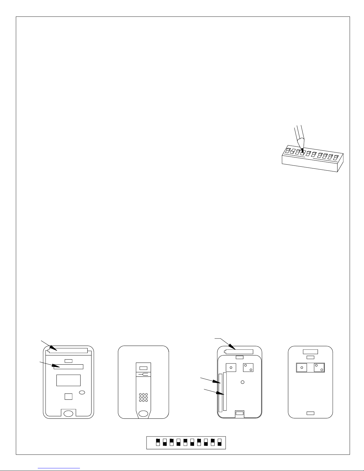
HH/RFT-1 Transmitter and HH/RFT-2 Transmitter
The HH/RFT hand held transmitters are used in conjunction with the 800RFR radio frequency
receiver. Under normal conditions, it will provide reliable activation of the ED800 within a
distance of 50 feet.
Select the code for the transmitters. The code must be identical to the code for the receiver which
is intended to be signaled. To access the code switch, remove the lower cover of the housing,
exposing the battery and the code switch. Refer to the code selection for 800RFR Radio Frequency
Receiver. Connect the 9 volt battery at this time.
If desired, a belt clip can be attached to the back of the transmitter housing by
sliding the clip completely into the slot provided.
The replacement battery is 9 volt NEDA 1604 (Eveready 216 or equivalent). If
the red LED on the transmitter fails to light when the button is depressed, it is
most likely that the battery is weak or dead, and should be replaced.
1
CODE SWITCH
2
3
4
5
o
p
e
n
6
7
8
9
After installation is complete, check for proper operation.
KC/RFT-1 Transmitter and KC/RFT-2 Transmitter
The KC/RFT key chain transmitters are used in conjunction with the RFR radio frequency
receiver. Under normal conditions, it will provide reliable activation of the ED 800 within a
distance of 50 feet. Select the code for the transmitter. The code must be identical to the code
for the receiver which is intended to be signalled. To access the code switch, KC/RFT-1
separate the two halves of the transmitter case by inserting a coin in the side slot and twisting.
KC/RFT-2 remove the phillips head screw on back of case and carefully separate the two halves
exposing the circuit board and battery.
Refer to the code selection for 800RFR Radio Frequency Receiver. The replacement battery is a 12
volt alkaline lighter battery (Eveready A23 or equivalent).NOTE: If the red LED on the transmitter
fails to light when the button is depressed it is most likely that the battery is weak or dead and
should be replaced. It is required that the correct polarity is observed when replacing the battery.
After installation is complete, check for proper operation.
1
0
BATTERY
-+
CODE
SWITCH
HH/RFT-1
TRANSMITTER WITH TOP
HALF OF CASE REMOVED
HH/RFT-1
TRANSMITTER TOP COVER
ON
SV
OFF 9A
BATTERY
-
KC/RFT-2
TRANSMITTER TOP COVER
CODE
SWITCH #1
CODE
SWITCH #2
12345 768
9
+
KC/RFT-2
TRANSMITTER WITH TOP
HALF OF CASE REMOVED
1
0
ED800-22 08102710 05/07
Page 23
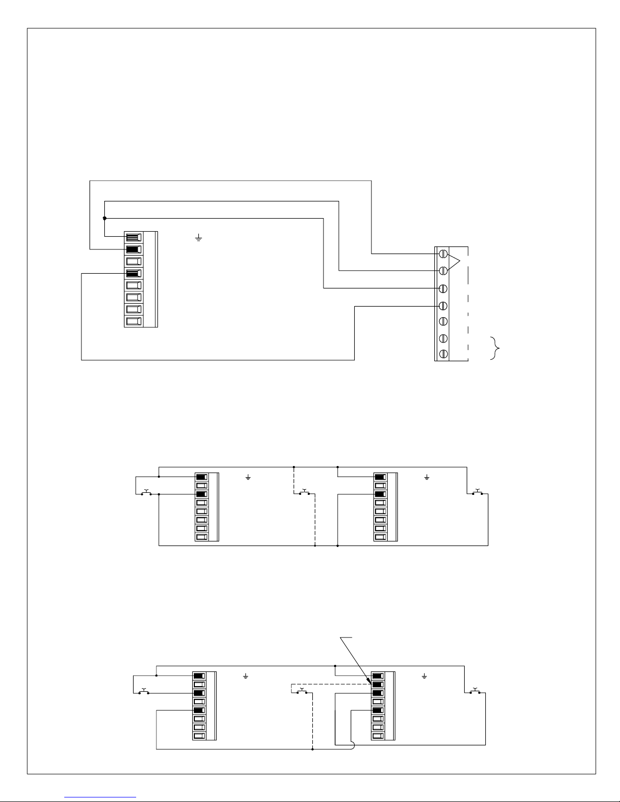
PS-1 Presence Sensor
BUSY SWING (SAFETY)
The ED800 has a built-in safety circuit which can be interfaced with an optional presence sensor.
When activated, the safety circuit prevents the door from receiving an "open trigger" signal.
Additionally, when the door is in the open position, the safety circuit will now act as an "open
trigger" signal, keeping the door open until the signal is no longer present. The use of the safety
circuit is optional and not required. However, by utilizing the safety circuit, the ultimate Safety and
convenience can be realized. The Safety circuit is activated by making a contact between " Busy
Swing (Safety)" and "Ground".
13
GROUND
2
+12VDC
OPEN TRIGGER
4
BUSY SWING (SAFETY)
5
VESTIBULE
6
NO
7
C
8
NC
12-24 VAC/VDC + 10°
COM
NO
NC
ED800
DATA (-)
DATA (+)
PS-1
NOT USED
BY ED800
VESTIBULE FUNCTION
The ED 800 can provide two different types of vestibule functions depending on the method of
wiring.
SIMULTANEOUS OPERATION
In this operation, both doors will open at the same time. The switch for each door and the
optional switch inside the vestibule will cause both doors to open at the same time.
INTERIOR SWITCH
1
GROUND
23
+12VDC
OPEN TRIGGER
BUSY SWING (SAFETY)
54
VESTIBULE
NO
76
C
8
NC
INTERIOR ED800
OPTIONAL SWITCH
INSIDE VESTIBULE
1
GROUND
23
+12VDC
OPEN TRIGGER
47
BUSY SWING (SAFETY)
5
VESTIBULE
6
NO
C
8
NC
EXTERIOR ED 800
EXTERIOR SWITCH
SEQUENTIAL OPERATION (SINGLE DOORS)
In this operation, the doors will open in sequence. The switch at each door will activate that door.
After that door closes completely, the other door will be activated. For example, when the
exterior switch is depressed the exterior door will open. When the exterior door closes
completely, the interior door will then open. This operation is the same in both directions. The
optional switch inside the vestibule opens both doors simultaneously.
Note: To one operator or the other, but not to both.
12
INTERIOR SWITCH
3
4
57
6
INTERIOR ED800
GROUND
+12VDC
OPEN TRIGGER
BUSY SWING (SAFETY)
VESTIBULE
NO
C
8
NC
1
GROUND
OPTIONAL SWITCH
INSIDE VESTIBULE
23 5
+12VDC
OPEN TRIGGER
4
BUSY SWING (SAFETY)
VESTIBULE
NO
76
C
8
NC
EXTERIOR ED 800
EXTERIOR SWITCH
ED800-23 08102710 05/07
Page 24
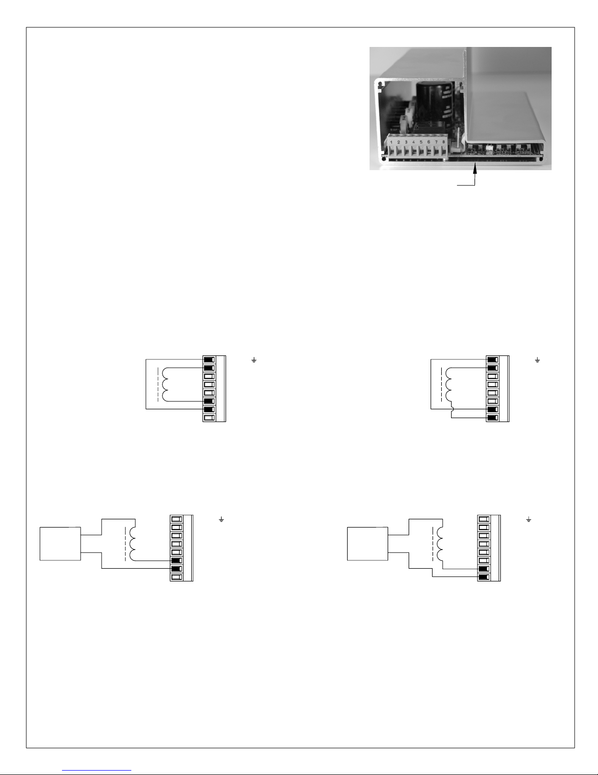
LATCH DELAY SWITCH
Toggle switch must be placed in the "ON" position (to the right)
to allow ED800 to delay for 1/2 second
before opening door when Electric Latch,
Strike or Magnetic Locks are interfaced.
LATCH DELAY OFF/ON SWITCH
STRIKE INTERFACE
The ED 800 can coordinate the release of an electric strike with the operation of the door. Upon
activation of the unit, a signal is immediately sent to operate the strike. The signal will last until
the door is open approximately 10°. Door activation may be delayed for 1/2 second to allow the
strike to operate (See page 16). The strike will only be signalled when the door is in the closed
position to eliminate unnecessary operation.
A 12 Volt DC fail secure electric strike or fail safe electric strike may be powered directly
by the ED 800. The maximum power draw is 500 milliamps.
FAIL SECURE FAIL SAFE
FAIL SECURE STRIKE
12 VDC STRIKE
1
467
532
8
ED800
GROUND
+12VDC
OPEN TRIGGER
BUSY SWING (SAFETY)
VESTIBULE
NO
C
NC
FAIL SAFE
12 VDC STRIKE
654321
7
8
ED800
GROUND
+12VDC
OPEN TRIGGER
BUSY SWING (SAFETY)
VESTIBULE
NO
C
NC
For 24 Volt AC, 24 Volt DC and 12 Volt AC fail secure electric strike, magnetic lock or fail safe
electric strike , the ED 800 provides a switch to control the strike. A separate power supply is
required for these applications.
FAIL SECURE
POWER
SUPPLY
STRIKE
ED800
12 VAC, 24 VAC, OR 24 VDC STRIKES/MAG. LOCKS
The maximum switch rating is 48 Volts AC or DC at 1amp.
1
GROUND
+12VDC
OPEN TRIGGER
467
BUSY SWING (SAFETY)
532
VESTIBULE
NO
C
8
NC
POWER
SUPPLY
FAIL SAFE
MAG. LOCK
OR STRIKE
ED800
GROUND
2
+12VDC
OPEN TRIGGER
BUSY SWING (SAFETY)
5431
VESTIBULE
NO
76
C
8
NC
LATCH RETRACTION
An electric latch retraction function can be coordinated with the ED 800. The ED 800 provides a
normally open set of contacts which close momentarily to act as a switch to signal the power
supply for the latch retraction. When activated, the contacts close immediately and stay closed
until the door is open approximately 10° to provide the signal to the power supply. Door
activation may be delayed by 1/2 second to allow the latch to retract (See page 16).
power supply is required for the latch retraction function.
A separate
ED800-24 08102710 05/07
Page 25
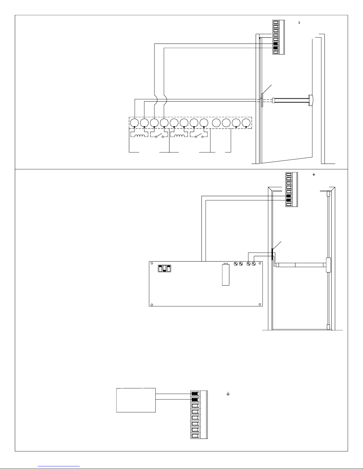
Typical wiring diagram for the ED 800 with ES100
Power Supply and ES8000 exit device.
ES100
POWER SUPPLY
1234
5678
10911
12
1
GROUND
275634
+12VDC
OPEN TRIGGER
BUSY SWING (SAFETY)
VESTIBULE
NO
C
8
NC
ED800
ES-105
POWER
TRANSFER
ES8000
EXIT DEVICE
TURN OFF 120 VAC POWER BEFORE
MAKING ANY CONNECTIONS OR SERVICE.
(+)
OUTPUT
TERMINALS
24 VDC
(-)
(IN)
ZONE 1
CONTROL
SWITCH
(+)
(+)
OUTPUT
TERMINALS
24 VDC
(IN)
ZONE 2
CONTROL
SWITCH
(+)(-)
NO
CONNECTIONS
Refer to ES100 Installation Instructions for complete wiring information.
Typical wiring diagram for the ED800 with
PS501 Power Supply and ES5000 or ES9000
Exit Device.
(ES5000 MANUFACTURED AFTER 5/06)
INPUT
OUTPUT B
120 VAC
INPUT
OUTPUT A
DRY
CONTACT
8
7
INPUT B
6
FIRE
CONTACT
3
4
5
CONTACT
12
DRY
FIRE
CONTACT
INPUT A
PS 501 POWER SUPPLY
(2X) 24VDC, 1AMP
(2X) 16AMP SURGE, .2 SEC.
-
B
DELAY
ADJUSTMENT
PS501
POWER SUPPLY
TURN OFF 120 VAC POWER BEFORE
MAKING ANY CONNECTIONS OR SERVICE.
DIP SWITCH
ON
OFF
+
24VDC
OUTPUTS
123 645 7
GROUND
+12VDC
OPEN TRIGGER
BUSY SWING (SAFETY)
VESTIBULE
NO
C
8
NC
ED800
ES-105
POWER
TRANSFER
+-
A
ES5000 SERIES
ES9000 SERIES
EXIT DEVICE
Refer to PS501 Installation Instructions for complete wiring information.
AUXILIARY POWER OUTPUT
The ED 800 is equipped with an auxiliary power output terminal which can be used to power
accessories such as electric strikes or radio frequency receivers. This terminal provides a
nominal 12 Volts DC filtered unregulated power source. The voltage range is from 10 to 25 volts
at 500 milliamps.
More than one accessory can be powered by the auxiliary power output
terminal, however the combined power draw can not exceed 500 milliamps.
12 VDC
ACCESSORY
-
+
ED800
ED800-25
1
GROUND
+12VDC
OPEN TRIGGER
467
BUSY SWING (SAFETY)
532
VESTIBULE
NO
C
8
NC
08102710 05/07
Page 26
Page 27
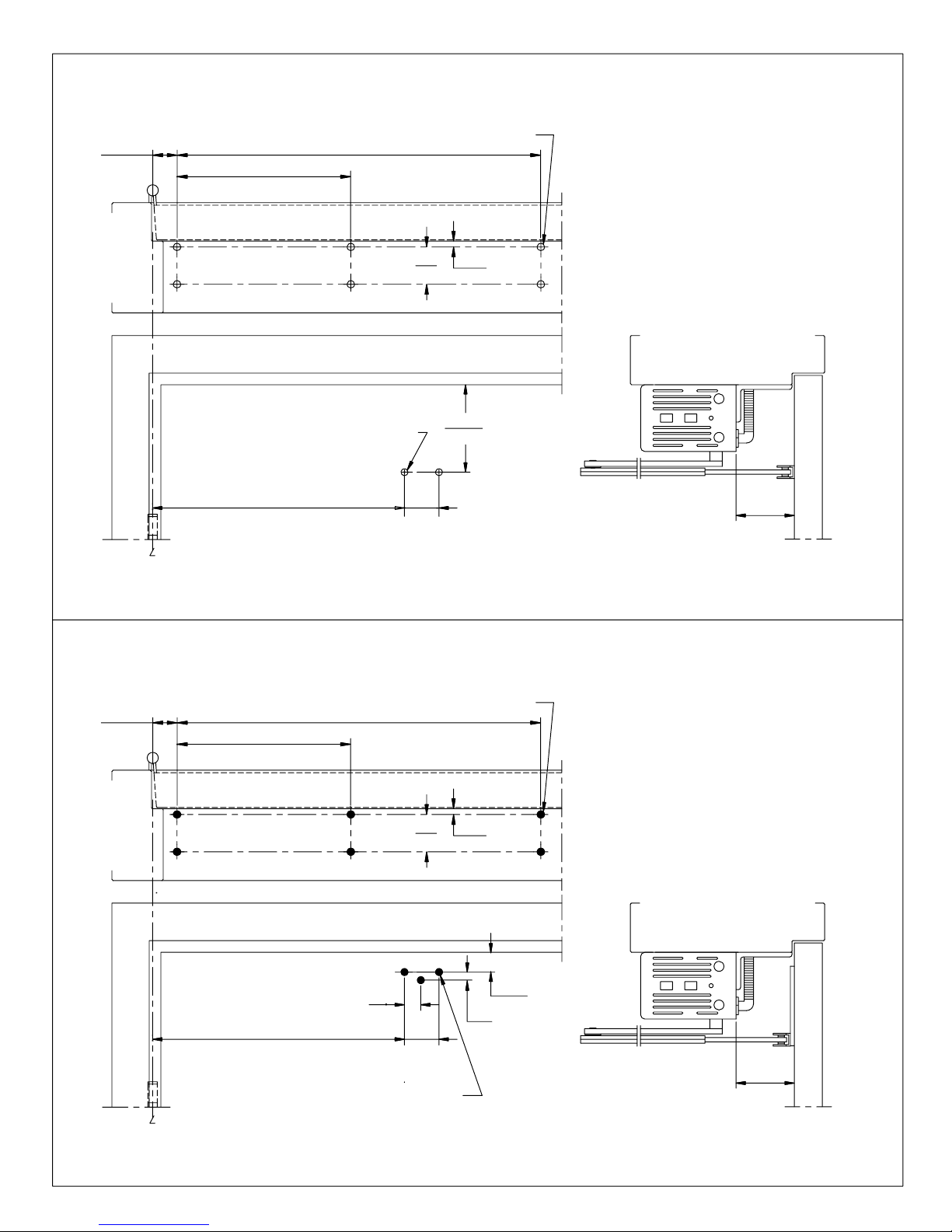
ED 800J x 870 ANGLE BRACKET - TOP JAMB INSTALLATION TEMPLATE
FOR 1/4-20 MACHINE SCREWS USE No.7 (0.201") DRILL
1-5/16
(33)
FOR 1/4-20 MACHINE SCREWS USE No.7 DRILL
OF 4-1/2" WIDE HINGE, 3/4" OFFSET PIVOT,
C
ED800J
TOP JAMB INSTALLATION - (PUSH SIDE MOUNT)
WITH 870 ANGLE BRACKET
10-3/16
(259)
FOR No.14 WOOD SCREWS USE 5/32" DRILL
TWO (2) HOLES IN DOOR FOR ARM SHOE
FOR SEX NUTS USE 3/8" DRILL
12-5/8
(321)
FOR No. 14 WOOD SCREWS USE 5/32" DRILL
SIX (6) HOLES IN FRAME FOR BRACKET
(51)
1-3/4
(44)
2
20-3/8
(518)
6-1/8
5/16
(8)
(156)
SEE NOTE #5
NOTES:
1. DO NOT SCALE DRAWING.
2. DIMENSIONS ARE IN INCHES/(MM).
3. LEFT HAND DOOR SHOWN.
4. CAUTION: SEX NUTS ARE RECOMMENDED FOR
ATTACHMENT OF COMPONENTS ON COMPOSITE
DOORS OR LABELED FIRE DOORS.
5. ALWAYS LOCATE ARM SHOE FROM 870 BRACKET
MOUNTING SURFACE.
6. MAXIMUM OPENING ANGLE 115°.
7. DOORS AND FRAMES MUST BE PROPERLY
REINFORCED.
3
(76)
TEMPLATE No. ED800-SP1 Rev.02/95
ED 800J x 870 ANGLE BRACKET x 831 ARM SHOE DROP PLATE
- TOP JAMB INSTALLATION TEMPLATE
FOR 1/4-20 MACHINE SCREWS USE No.7 (0.201") DRILL
1-5/16
(33)
OF 4-1/2" WIDE HINGE, 3/4" OFFSET PIVOT,
C
ED800J
TOP JAMB INSTALLATION - (PUSH SIDE MOUNT)
WITH 870 ANGLE BRACKET X 831 ARM SHOE DROP PLATE
10-3/16
(259)
12-5/8
(321)
FOR 1/4-20 MACHINE SCREWS USE No.7 DRILL
FOR No.14 WOOD SCREWS USE 5/32" DRILL
FOR No. 14 WOOD SCREWS USE 5/32" DRILL
SIX (6) HOLES IN FRAME FOR BRACKET
7/8
(22)
FOR SEX NUTS USE 3/8" DRILL
THREE (3) HOLES IN DOOR FOR PLATE
20-3/8
(518)
2
(51)
1-3/4
(44)
5/16
NOTES:
1. DO NOT SCALE DRAWING.
2. DIMENSIONS ARE IN INCHES/(MM).
3. LEFT HAND DOOR SHOWN.
4. CAUTION: SEX NUTS ARE RECOMMENDED FOR
ATTACHMENT OF COMPONENTS ON COMPOSITE
DOORS OR LABELED FIRE DOORS.
5. ALWAYS LOCATE 830 PLATE FROM 870
BRACKET MOUNTING SURFACE.
6. MAXIMUM OPENING ANGLE 115°.
7. DOORS AND FRAMES MUST BE PROPERLY
(8)
1-1/4
SEE NOTE #5
(32)
1/2
(13)
REINFORCED.
3
(76)
TEMPLATE No. ED800-SP3 Rev.08/95
08102710 05/07ED800-27
Page 28

ELECTRICAL SPECIFICATIONS
ED 800
Power Requirements:
Current:
Fuse:
Auxiliary Power O utput:
Max.Strike Switch Rating:
WS-1 Wall Switch
Switch Type:
Switch Rating:
120 Volts AC +10 -15%, 50/60 Hz
2 Amp
3 Amp - type AGC - size 1/4" x 1 1/4"
12 Volts (nominal) filtered unregulated
Range 10 to 25 Volts DC @ 500mA
48 VAC/DC @ 1 Amp Max.(terminals 6,7, 8)
SPDT
15 Amp @ 125 or 250 Volts AC
FS-1 Wall Switch
Switch Type:
Switch Rating:
RFR Radio Frequency Receiver
Frequency:
Supply Voltage:
Power Consumption (rest):
Power Consumption (relay on)
Relay Contact Rating:
Numbers of Codes:
WS/RFT-1 Wall Switch
Switch Type:
Switch Rating:
Frequency:
Range:
Numbers of Codes:
Battery Type:
SPDT
15 Amp @ 125 or 250 Volts AC
300 MHz std. or 310 MHz jumper selectable
12 - 30 Volts AC/DC
16mA
50mA
30 Volts AC/DC @ 5 Amp Max.
1024
SPDT
15 Amp @ 125 or 250 Volts
300 MHz
Normally 50 ft. - depending on local conditions
1024
9 Volt NEDA 1604 (Eveready 216 or equivalent)
HH/RFT-1, HH/RFT-2 Transmitter
Transmitter Type:
Frequency:
Range:
Numbers of Codes:
Battery Type:
KC/RFT-1, KC/RFT-2 Transmitter
Transmitter Type:
Frequency:
Range:
Numbers of Codes:
Battery Type:
Hand held
300 MHz
Normally 50 ft. - depending on local conditions
1024
9 Volt NEDA 1604 (Eveready 216 or equivalent)
Key chain
300 MHz
Normally 50 ft. - depending on local conditions
1024
12 Volt (Eveready A23 or equivalent)
ED800-28
08102710 05/07
 Loading...