

Page 1
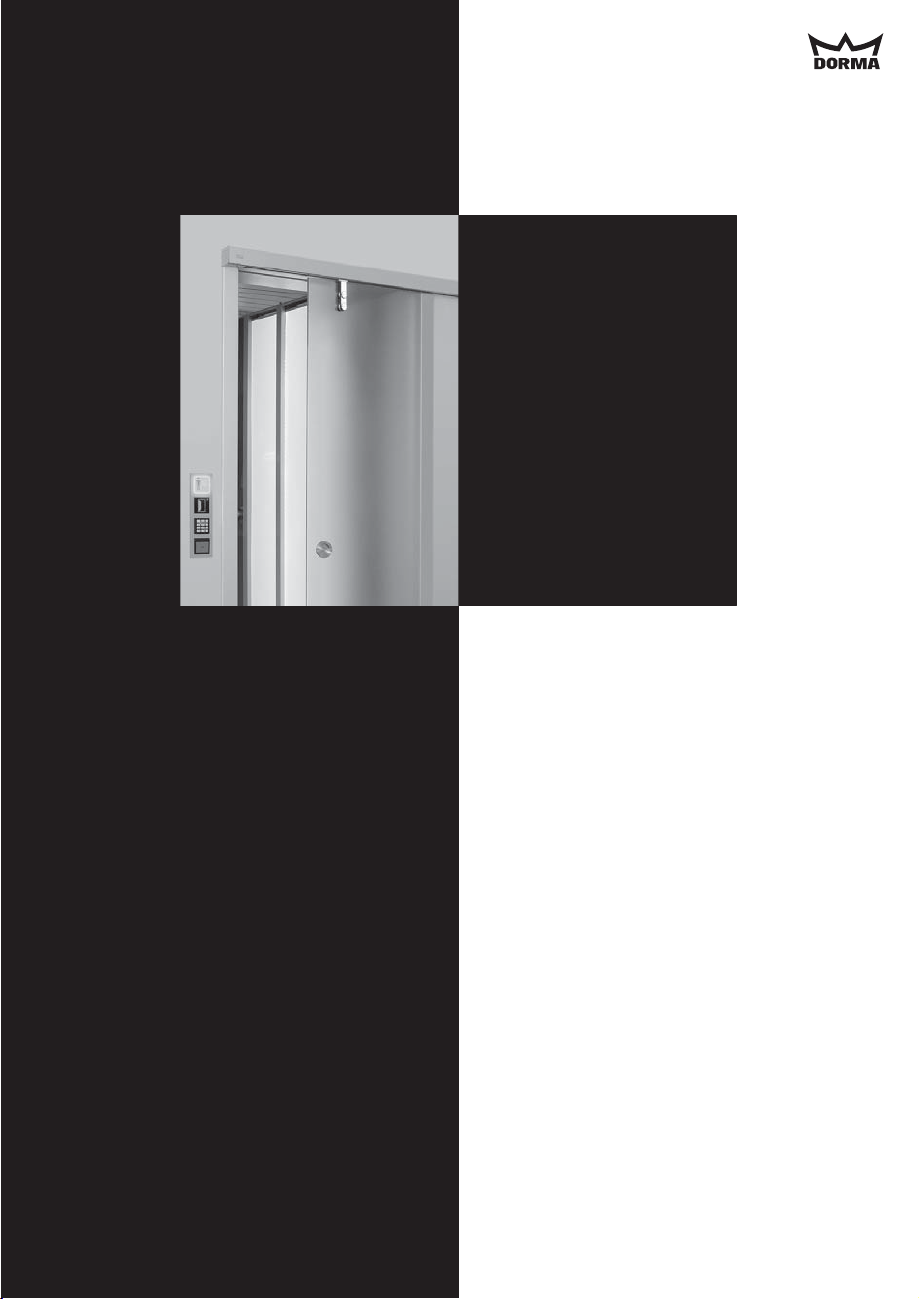
DORMA CS 80 MAGNEO
CS 80
MAGNEO
Automatic
sliding door operator
Technical
Documentation
Read the manual before
the assembly carefully!
Page 2
DORMA CS 80 MAGNEO
Dear customer,
Thank you for buying a product from our product range.
The DORMA brand stands for first-class and scrutinised quality products offering extremely
high safety standards.
This documentation contains important information for the safe installation of the system.
Please read these instructions thoroughly before you mount, install and use the
CS 80 MAGNEO.
Keep these instructions for further reference and make them available to other users.
Yours faithfully,
The DORMA-Team
Required tools:
·
Tape measure or folding rule respectively
·
Water level
·
Pencil
·
Drilling machine
·
Masonry drill bitØ6mm
·
Metal drill bitØ3and8mm
·
Socket wrench (10 mm)
·
Flat-bladed screwdriver for connection terminals of control unit.
·
Crosstip screwdriver for countersunk screws of wall connection.
·
Allen key, 4mm
·
Combination wrench, wrench size 10 mm and 13 mm
·
Long-nosed pliers for connection to terminals.
·
Adequate screws and wall plugs for the prevailing structures,
in case they are not made of brickwork or concrete.
Additionally for DORMA MANET fixing:
·
Allen key, 3 mm and 5 mm
Translation of the original documentation
2
Page 3
DORMA CS 80 MAGNEO
Contents
Page
1. Safety instructions 4 - 6
2. Functional Characteristics 7 - 8
3. Technical data and features 9
4. System overview 10
5. Before mounting 11
6. Installation instructions for on-wall mounting 14
7. Installation instructions for in-wall mounting
8. Connection diagrams 28
9. Cable channel 29
10. Connection of closing edge protection 30
11. Commissioning 31
12. Operation instructions 33 - 34
13. Commisssioning and maintenance according to DIN 18650-2, 5.1-5.4 35
14. Troubleshooting instructions 36 - 37
Manufacturer's declaration 38
Declaration of conformity 39
22-27
-13
-21
-32
REMARK
ADVISE
ATTENTION Here we will inform you of dangers that might cause damage to property
A remark will call your attention to important information that will
facilitate your work with the CS 80 MAGNEO.
An advice will warn you that you could damage the CS 80 MAGNEO
and explain how to avoid this.
or injure or kill people.
3
Page 4
DORMA CS 80 MAGNEO
1. Safety Instructions
1.1 Specified standard operation
CS 80 MAGNEO
The is only designed to open and close
with an admissible weight from 20 kg to 80 kg per door panel.
Do not allow children to play with the or rigidly mounted adjustment and/or
CS 80 MAGNEO
control devices. Keep remote controls out of reach of children.
A door kit is provided to make the connection with the door leaf.
1.2 Product-specific characteristics
CS 80 MAGNEO
The is suitable for application in escape routes, on fire and
smoke doors on exterior doors.
nor
neither nor
.
1.3 Standards, laws, codes and regulations
Residual risks
Automatic doors might cause hazards by crushing, shearing, hitting and drawing-in.
Depending on the structural conditions, the door version and the safety equipment,
residual risks cannot be excluded.
CS 80 MAGNEO as low-energy product according to German DIN 18650
(German Industrial Standard)
According to the German Industrial Standard DIN 18650, the movement range of an
automatic door always has to be protected (amongst others) by safety sensors.
However, there are special requirements for low-energy systems.
CS 80 MAGNEO
The meets the requirements of a low-energy operator according to the
standard by fulfilling the following requirements:
·
Reduced operating speeds (reduced dynamic forces at the door panel/contact forces)
·
Force limitation (reduced static forces at the door /contact forces)
Danger spots at closing edges
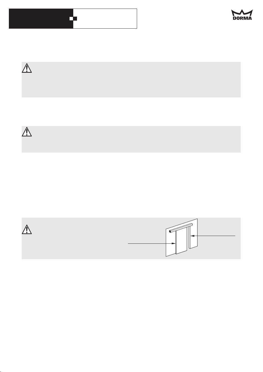
Automatic doors might cause hazards
by crushing, shearing, hitting and
drawing-in at the different
closing edges.
Secondary
closing edge
small and light interior doors
panel
Main
closing edge
Required protection equipment for CS 80 MAGNEO according to DIN 18650
The German Industrial Standard DIN 18650 stipulates different requirements regarding
the protection of the above-mentioned danger spots.
Systems with CS 80 MAGNEO offer the following benefits:
The system does not have to be equipped with additional protection equipment (not
·
compulsory).
The application of safety sensors at the closing edges as additional protection measure is
·
optional and lies in the discretion of the person performing the installation of the door
system - under consideration of the result of the individual risk assessment (please also
refer to Risk assessment , page 4).
Altogether the system offers a high safety standard!
·
4
Page 5
DORMA CS 80 MAGNEO
Safety requirements according to DIN 18650 in the Full Energy mode
The actuating forces are also limited in this mode. However, due to the higher contact
forces that can occur, a safety kit must be installed. This must be done by a specialist in
accordance with DIN 18650 or equivalent national safety regulations.
Risk assessment on the part of the installer
Special spatial conditions and certain user groups might make it sensible to equip the
application with safety sensors even when the system is operated in Low-Energy-Mode.
Whether this is required or not has to be assessed with the aid of an individual risk
assessment and must be considered during the planning of the system and by the
manufacturer, i.e. the party performing the installation of the system.
We would therefore ask you to have a look at our risk assessment form , which is
available on our homepage and will help you to perform the risk
www.dorma-magneo.com
assessment.
Special requirements regarding the protection of people in need of protection
In case the risk assessment reveals that there is a health risk or risk of injury when the
door hits a user in an unacceptable way, additional protection via safety equipment
(connection of safety sensors) is required. This is especially necessary when people in
need of protection (children, elderly people or disabled people) use the door.
These safety devices must be installed by a specialist in accordance with DIN 18650 or
equivalent national safety regulations.
1.4 Limitation of liability
CS 80 MAGNEO
The must only be used according to its specified standard operation.
DORMA GmbH + Co. KG
unauthorized modifications of the .
will not accept any liability for damages resulting from
CS 80 MAGNEO
1.5 Documentation
Using control elements, making adjustments or performing procedures that are not
described herein might cause electric shocks, danger caused by electric voltage/current
and/or dangers due to mechanical incidents.
It is important for your personal safety to abide by the instructions mentioned in this
documentation. An incorrectly performed installation of the system might cause serious
injuries.
Please keep this documentation for later reference.
1.6 General information regarding the installation of the system
The CS 80 MAGNEO must be disconnected from power supply (de-energized) when
performing mounting or installation work. Remove the power plug, or, in case of
permanent power supply, switch off fuse.
Secure the working area against unauthorized access of other people.
·
Falling items or tools might cause injuries.
In any case, the way of mounting and the mounting equipment, like for example screws
·
and wall plugs, have to be adequate with regard to the structural conditions (concrete,
wood, plasterboard etc.)
5
Page 6
DORMA CS 80 MAGNEO
·
As soon as you have relaxed the screws of the end stop, both the end stop and the carrier
could fall out of the operator. Therefore you should always hold the operator straight.
Pay attention that no water or other liquids drop on or into the .
·
·
The carrier contains strong permanent magnets and must not be removed.
Never stick metal objects inside the openings of the .
·
CS 80 MAGNEO
CS 80 MAGNEO
Otherwise you could sustain an electric shock.
Never put you hand inside the in order to avoid injuries.
·
Only specially qualified staff may open the power supply housing.
·
Lay the power cord so that nobody can trip over the cable or unplug it by mistake.
·
Do not operate the when the power cord is damaged.
·
Always pull at the plug and never at the cable when unplugging the power supply.
·
Only operate the mains switch at the header profile while the door stands still or is
·
CS 80 MAGNEO
CS 80 MAGNEO
permanently open.
No pushbuttons/switches, pictures etc. must be located within the door's movement
·
range. Baseboards have to be removed if required.
Following the successful installation of the system, you have to check the settings as well
·
as the and the safety devices for proper functioning.
CS 80 MAGNEO
The installation described herein is only an example. Structural or local conditions,
·
available tools or other conditions might suggest a different approach.
· This device must not be disposed of as domestic waste.
CS 80 MAGNEO - Awarded safety
Developed according to the latest safety standards:
Low-Energy-Mode in accordance with DIN standard
Tested Safety
- mark
The TÜV certificate and the certificate can be obtained
from the manufacturer on demand.
6
Page 7
DORMA CS 80 MAGNEO
2. Functional Characteristics
2.1 General information
The is a single-panel
CS 80 MAGNEO
electromechanical sliding door operator for
small and light interior doors with an
admissible weight from 20 kg to 80 kg per
door panel. The opening and closing speed
respectively depend on the weight of the
door panel and can be adjusted via a
potentiometer (infinitely variable).
2.2 Commissioning
During the first commissioning of the
operator, the facility operator has to perform
a learning cycle according to the
commissioning instructions. When the
facility operator connects the system to the
power supply (plugs it in) the light indicator
at the operator will blink and the operator
has no function. The door can be opened
and closed manually. Following the learning
cycle the light indicator goes on and the
operator is ready for operation.
2.3 Energy modes
With the aid of a sealed switch (located
inside the operator), the system can be
switched from Low-Energy-Mode to FullEnergy-Mode (mandatory installation of
safety devices).
Low-Energy-Mode (Standard)
According to the standard (DIN 18650) the
force with which a door panel hits an
obstacle must be limited when a system is
operated in Low-Energy-Mode. Therefore the
operator moves the door panel at
correspondingly low speed and no additional
safety sensors are required. The
potentiometer (located inside the operator)
can only be used to reduce the speed.
Full-Energy-Mode
The forces are limited in this mode as well.
Due to the increased contact forces, safety
equipment is compulsory in most cases.
The speed is infinitely variable with the aid
of a potentiometer (located inside the
operator).
The closing cycle always remains in LowEnergy-Mode.
2.4 Operation modes
OFF:
AUTOMATIC:
PERMANENT
OPEN:
When the system is delivered, the
MAGNEO
An external program switch is required
to change the operation mode.
2.5 Functions in AUTOMATIC Mode
Push & Go
As soon as the door is moved manually into
opening direction by approximately 10 mm,
the operator will automatically move the door
panel further in the desired direction. The
door closes automatically.
Permanent Open via double-click
A double-click on the pushbutton (activate
the pushbutton twice in quick succession)
will open the door. When you double-click on
the button for a second time or move the
door panel by hand, the door will close.
Opening/closing via pushbutton
As soon as you push the button or move the
door manually the door will open. When you
push the button for a second time or move
the door panel by hand, the door will close.
The operator is switched off.
You can move the door by
hand.
When the system has been
activated via pushbutton,
radio remote control or similar,
the operator opens the door
and closes it on expiry of the
adjusted hold-open time.
The operator opens the door
and holds it in "open" position
until it receives another signal.
CS 80
is adjusted to AUTOMATIC Mode.
7
Page 8
DORMA CS 80 MAGNEO
Express-Function
The door can be moved manually in ist
operational direction and there will be no
extra resistance. However, when the
maximum speed is exceeded, the operational
resistance will increase in line with the
speed by which it is exceeded. As soon as
the user has released the door panel, the
operator will softly slow it down to maximum
speed. This function is activated during all
opening and closing cycles.
2.6 Safety functions
Static forces in Low-Energy-Mode
The system does not exceed a value of 67 N
during opening and closing cycles.
Opening cycle
As soon as the door hits an obstacle during
an opening cycle, it will immediately stop
and remain in its position for 3 seconds.
Then the operator will try to continue the
opening cycle. If the door panel hits an
obstacle three times during an opening
cycle, it will close.
Closing cycle
When the door panel hits an obstacle while
closing, it will immediately stop and perform
an opening cycle.
2.7 Safety sensors
You can install sensors to detect obstacles.
According to DIN 18650, an automatic
sensor test can be activated or deactivated
via the DIP switches located inside the
operator.
The door will stop immediately when the
sensor detects an obstacle during an
opening cycle and will continue the cycle as
soon as the obstacle has been removed. In
case the obstacle is not removed, the door
will close on expiry of the adjusted holdopen time.
The door will stop immediately and reverse
when the sensor detects an obstacle during
an closing cycle. This function is not
activated while the door is in "closed"
position (then the sensor is deactivated).
2.8 Power failure
In the event of a power failure, the door can
be opened and closed by hand.
However, in this case the operator does
not slow down (brake) the door panel, so
that the user has to move (hold) it all
the way by hand.
As soon as the voltage returns, the operator
will automatically perform a position
initialization.
During this position initialization, it is
essential that the movement range of
the door is free of obstacles.
8
Page 9
DORMA CS 80 MAGNEO
3. Technical data and features
Power supply:
Power supply: 220 230 V AC ±10%; 50/60 Hz
Fuse protection (by others): 10 A
Cable type: max. 3 x 1.5 mm²
Power consumption without external accessories:
Stand-By-Mode: 3.7 W
Automatic-Mode: max. 60 W
General information:
Temperature range: 0-40° C
Operating noise of operator: max. 55 dB (A)
Door panel height: max. 3000 mm
Door panel weight: 20 kg - 80 kg
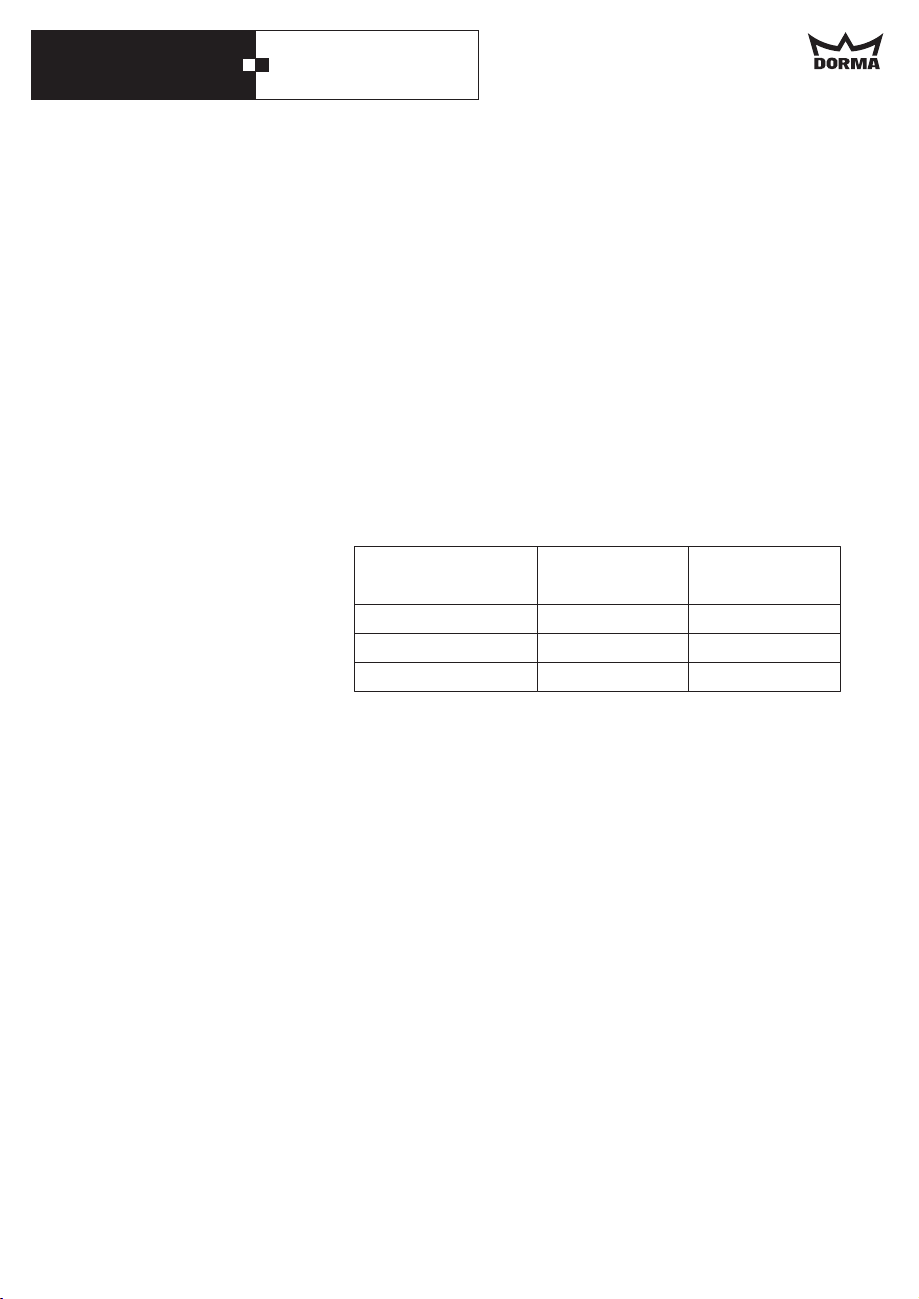
Weight of operator:
max. movement range
875 mm
1000 mm
1125 mm
Operator length
without cover
1750 mm
2000 mm
2250 mm
Weight of operator
8.6 kg
9.4 kg
10.2 kg
9
Page 10
DORMA CS 80 MAGNEO
8
7
6
5
4
3
2
1
ON
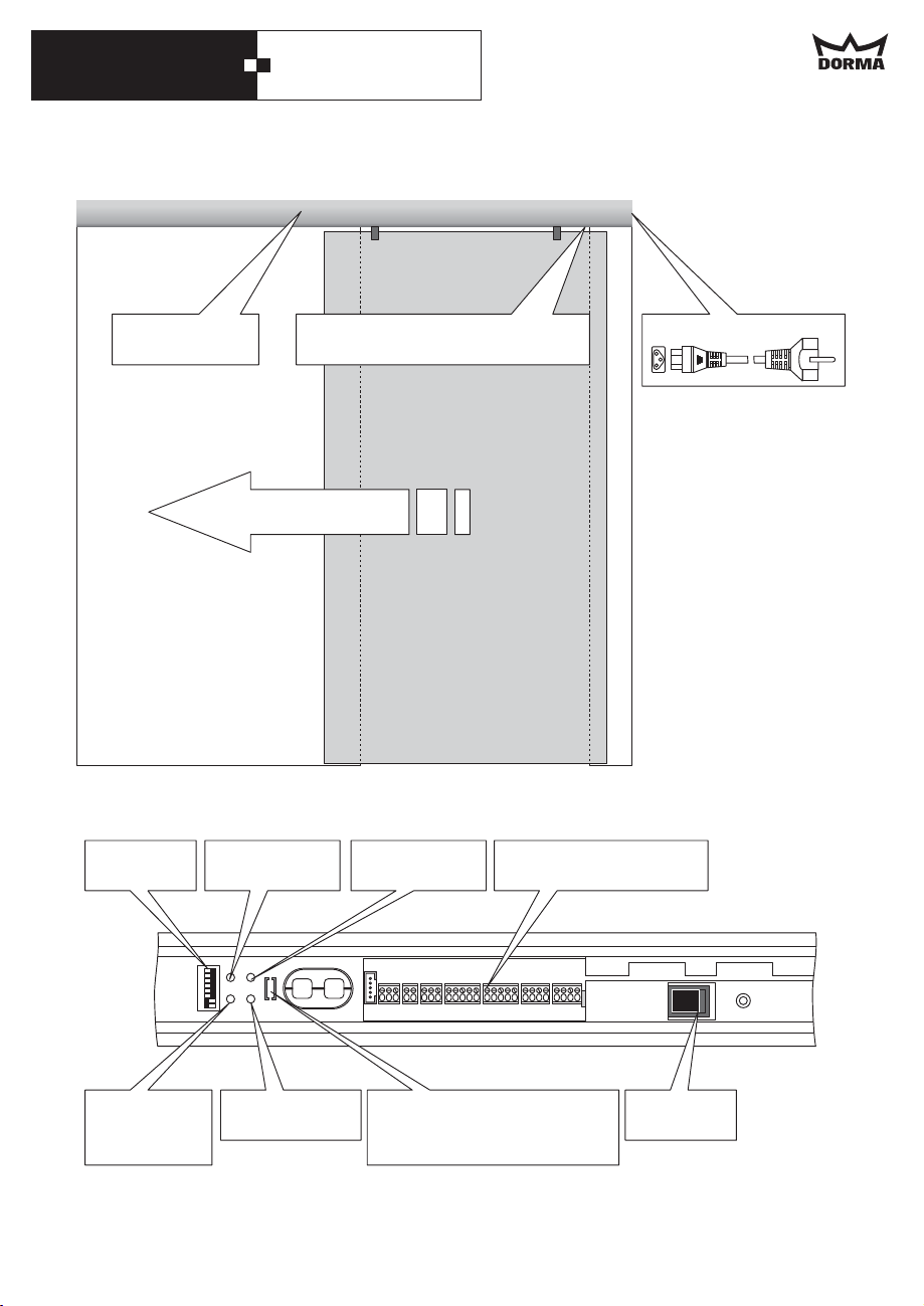
4. System overview
CS 80 MAGNEO
Control unit and connection
terminals for external accessories
Actuated opening direction
Control unit and connection terminals for external accessories
DIP switch
LED
light indicator
Potentiometer
hold-open time
Connection terminals for
external accessories
Power supply
Reset button
Start
learning cycle
10
Potentiometer
speed
Energy mode switch
(Full-Energy/Low-Energy)
(located below the seal)
Mains switch
Page 11
DORMA CS 80 MAGNEO
5. Before mounting
Basic requirements:
Work on electrical equipment may only be performed by properly qualified staff
(electricians).
·
The floor has to be level.
·
Glass door panels have to be made of safety glass.
·
The connection cables for external accessories (program switch etc.) must be located in
the close range of the operator before starting the installation of the system.
·
With in-wall mounting, the wall must not be closed before the system has been mounted.
When the system is installed with permanent power supply (the cable comes directly out
of the wall), ensure that the power supply line is dead (de-energized) during installation.
The power supply line, max. 3 x 1.5 (Schuko-type shockproof socket or permanent
power supply) must have a 10 A fuse protection.
Opening direction:
The connections of the operator are always located on the side where the door is when it
is in closed position.
Therefore the operator is symmetrical and can be turned the way you require it.
This installation instructions show the system with connection on the right side.
Thus the installation with connection on the left side is realised laterally reversed.
Please note:
In case you require additional accessories, please contact your local dealer.
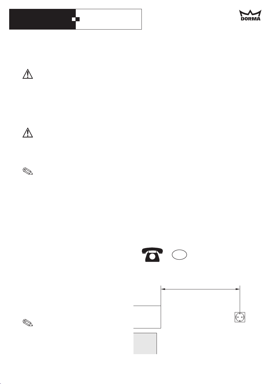
If you have technical questions or require help during the installation of the system, please
contact our hotline under the following number:
mm
2
Please call the following number in case
of technical problems or further questions:
The cable of the power supply line has a
length of 2.5 m. Thus a Schuko-type
shockproof socket (230 V AC, 50/60 Hz)
must be available within this distance.
For in-wall mounting:
When installing the socket, please
remember that you should be able to
reach it by hand.
GB
01462 477 602
max. 2200 mm
11
Page 12
DORMA CS 80 MAGNEO
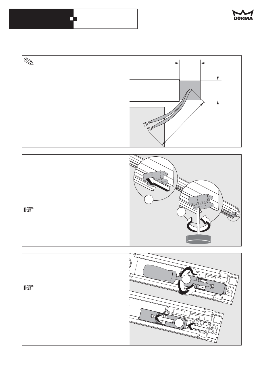
In order to facilitate the cabling inside
the operator, all cables should have a
length of at least 250 mm.
For on-wall mounting:
If you want all connection cables that are
coming out of the wall not to be seen after
the installation (only possible with
permanent power supply), they have to come
out of the wall within an area of 60 x 60 mm
on the side where the connections of the
operator are located.
Installation with permanent power supply:
When the system is installed with permanent
power supply, the internal power supply
socket has to be removed.
Proceed as follows:
Relax the screws at the end stop and move
the end stop to the centre of the system.
Do not remove or screw down the end
stop.
60 mm
60 mm
min. 250 mm
2.
1.
Then relax the screw in the cover of the
power supply housing and remove the cover
(on the side where the connections are
located).
Keep the cover and the screw in a safe
place as you will require it later.
12
1.
2.
5.
2.
4.
1.
Page 13
DORMA CS 80 MAGNEO
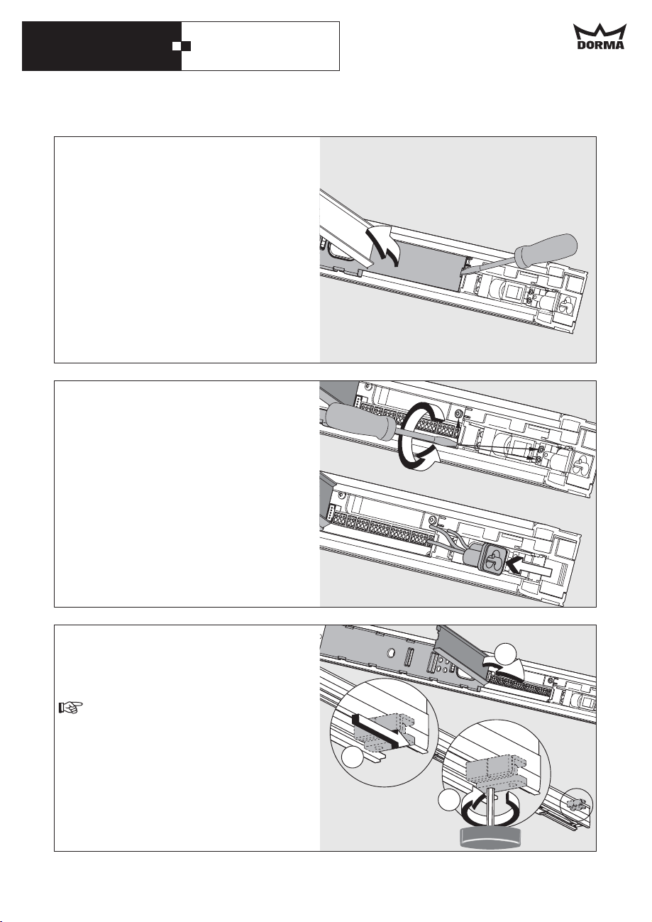
Open the cover of the control unit
careful
housing by levering it out with the
tip of a screwdriver.
flat-bladed
Relax the screws of the connection terminals
and remove the internal Schuko-type
shockproof socket.
Then close the cover of the control unit
housing.
Move the end stop to the end of the channel
and screw it down.
The end stop must not overlap.
2.
3.
1.
1.
13
Page 14
DORMA CS 80 MAGNEO
6. Installation instructions for on-wall mounting
Mounting procedure
If there is a door frame, you have to shim the angle brackets with
the shim plate (optional).
1. Auxiliary lines for positioning purposes
See bottom of this page.
2.a Installation without shim plate
See Page 15 and 16.
2.b Installation with shim plate
See Page 17.
3. Further installation
See Page 18 21.
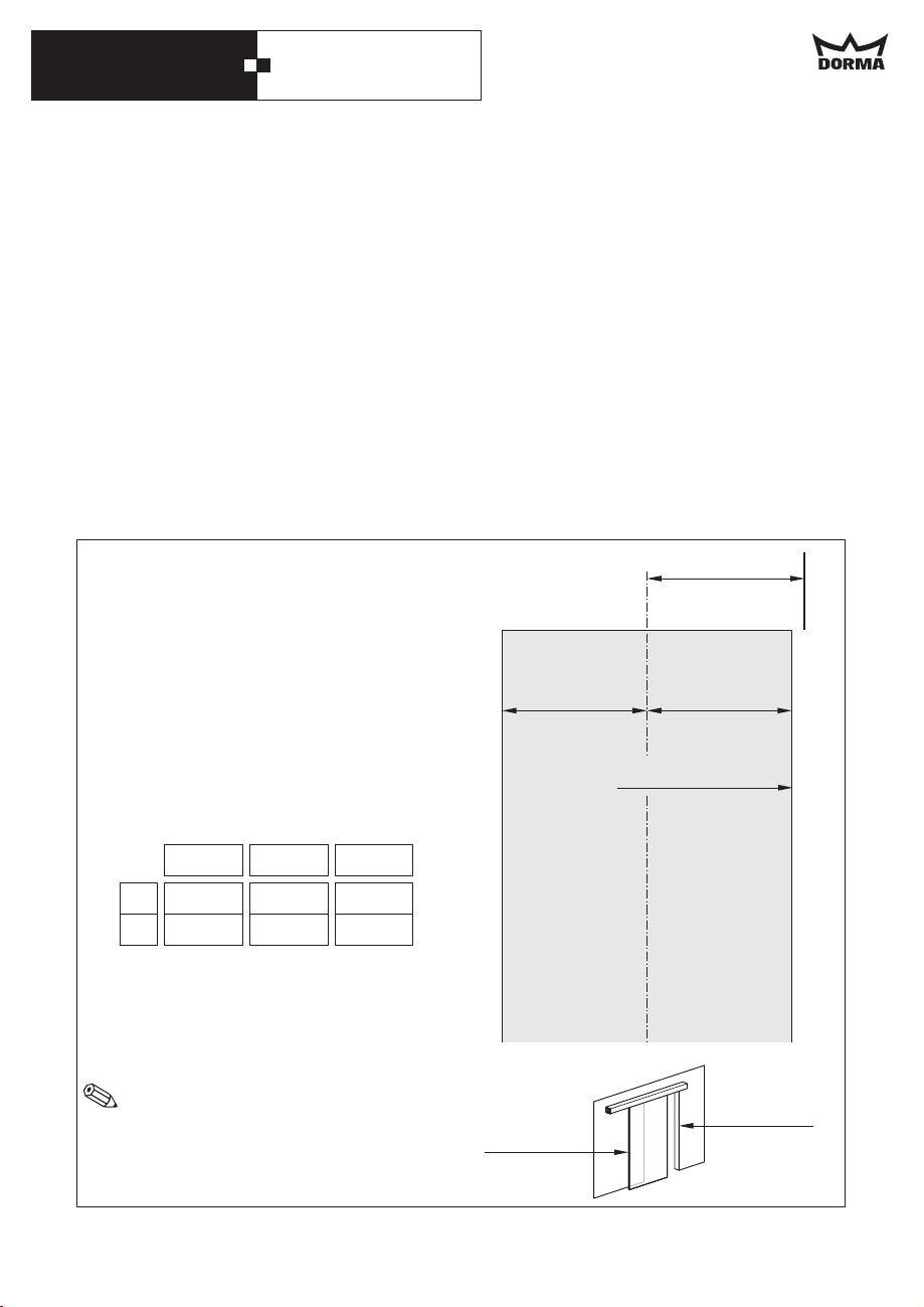
Reference lines for positioning purposes.
For the installation without shim plate
Mark the centre of the passage on the wall.
For the installation with shim plate
Mark the centre of the passage on the wall.
Please have a look at the table for the
required dimension for your operator.
corresponds to the operator length.
L
Now mark the reference line.
Always mark the reference line on the side of
the main closing edge.
1750 2000 2250
L
437.5 500 562.5
L/4
In case the door panel shall not be
positioned in the centre of the passage,
the bracket or shim plate has to be
shifted by the desired dimension.
L/4
875 1000 1125
Secondary
closing edge
L/4
==
Main closing edge
Main
closing edge
Reference
line
14
Page 15
DORMA CS 80 MAGNEO
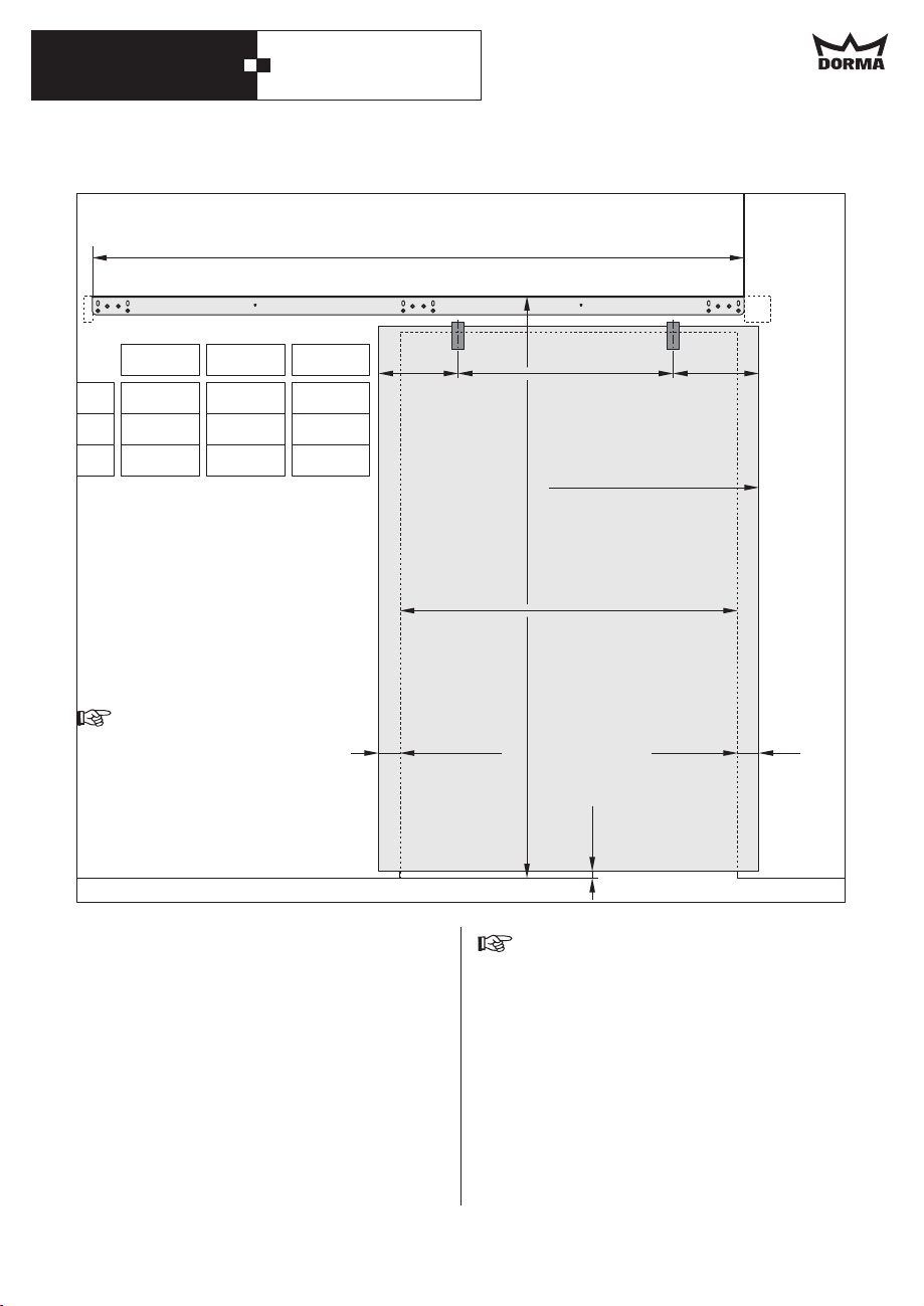
L
Reference
line
875 1.000 1.125
810 935 1.060
PW
1.750 2.000 2.250
L
575 700 825
C
With
wooden door panel:
X
= Door panel height + 78 mm
With glass clamping rail:
= Door panel height + 114 mm
X
With DORMA MANET
single-point fixings
= Door panel height + 74 mm
X
Dimension X has to be measured
at the highest point of the floor
within the movement range of
the door system.
·
The "closed" position is always located
on the side where the connections are.
Dimension L (Length of operator and
·
fixing bracket) is measured without end
caps.
Take dimension from floor level; then
X
position and mark the upper edge of the
fixing bracket onto the wall.
==
C
Side with
connections
Closed position
X
Passage width (PW)
Projection
Projection
max. 65 mm
6mm
The distance between the bottom edge
of the door panel and the floor should
amount to 6 mm, however, it must not
exceed 8 mm.
15
Page 16
DORMA CS 80 MAGNEO
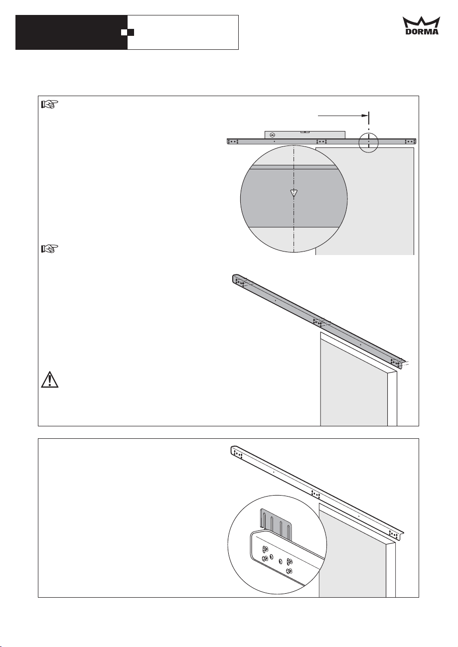
Before drilling the holes, check if there
are cables or pipes in the close range of
the drill holes.
Position the fixing bracket onto the centre
line.
Ensure that the bottom vertex of the triangle
is located exactly on the centre line.
Align the fixing bracket so that it is level.
Fix the bracket with screws
(one screw respectively per one oblong hole
on each side).
Use adequate wall plugs and screws
depending on the prevailing structure
when fixing the bracket.
The supplied screws and wall plugs are
suitable for concrete and brickwork.
Recheck the fixing bracket for exact
positioning.
Drill the further holes through the drill holes
in the fixing bracket and fix the bracket with
at least 12 screws.
The load-bearing capacity of the fixing
bracket must amount to at least 240 kg.
Center line
In case of uneven walls you have to shim the
bracket so that it does not bend.
Use the enclosed distance plates in different
sizes for this purpose.
16
Page 17
DORMA CS 80 MAGNEO
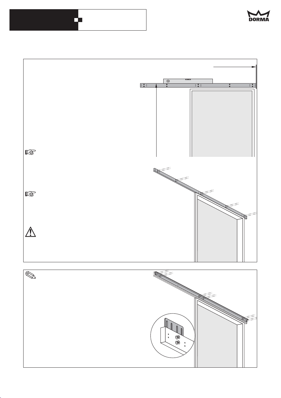
Mounting with shim plate
Position the shim plate at the reference line.
Calculate the dimension from the floor to the
upper edge of the shim plate as follows:
Door panel height + 78 mm
When using DORMA MANET single-point
fixings:
Door panel height + 74 mm
Align the shim plate so that it is level and
mark the drill holes.
Before drilling the holes, check if there
are cables or pipes in the close range of
the drill holes.
Drill the marked holes and fix the shim
plate.
Use adequate wall plugs and screws
with respect to the prevailing structure.
The supplied screws and wall plugs are
suitable for concrete and brickwork.
The load-bearing capacity of the fixing
bracket must amount to at least 240 kg.
Reference line
In case the frame is ticker than 10 mm,
you have to underlay the shim plate
with the enclosed distance plates so
that it is flush with the door frame.
Use 12 screws to fix the bracket to the shim
plate.
17
Page 18
DORMA CS 80 MAGNEO
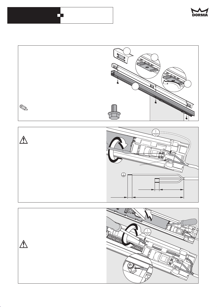
1.
Adhere 3 pieces of felt equally onto
the bracket.
2.
The openings of the door panel
suspension have to point to the front
3.
When using MANET fixings, the door
panel suspensions have to be
unscrewed.
4.
Fix the operator below the bracket with
6 hexagon screws (lock screws) .
(8 Nm)
You will have to move the carrier in
order to reach all 6 holes
.
Connection of 230 V permanent power supply
Work on electrical equipment may only
be performed by properly qualified staff
(electricians).
Before starting with the installation,
make sure that the power supply line is
dead (de-energized).
Relax the end stop and move it to the centre
of the system (see page 11, picture in the
middle).
Cut the leads to length, dismantle them and
connect L1 and N to the connection
terminals of the power supply.
1.
2.
.
4.
3.
6x
L1
N
L1
N
35 mm
6mm
6mm
150 mm
Lever out the cover at the control unit
housing with the aid of a screwdriver.
Lay the grounding line through the housing
of the operator as shown in the picture and
connect it to the grounding terminal (PE).
The grounding (PE) has to be connected
in any case.
Connect all external accessories but the
safety sensors.
Please refer to the instructions for the cable
channel on page 26.
18
Page 19
DORMA CS 80 MAGNEO
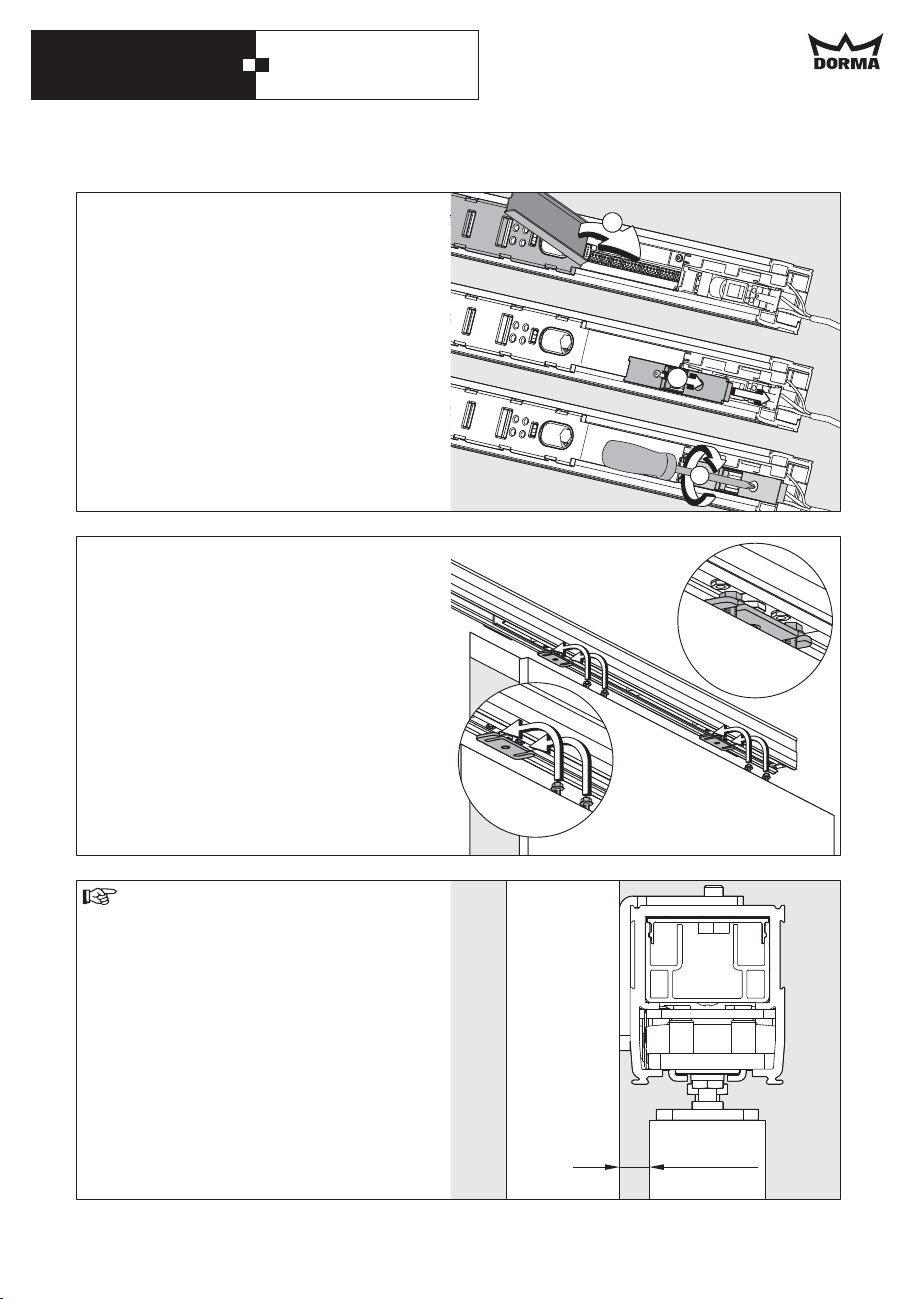
Close the cover of the control unit housing.
Fix and screw down the cover of the power
supply housing.
Move the end stop to the end of the channel
and screw it down thoroughly (see page 13,
picture at the bottom).
Inser the panel into the door panel
suspension as indicated in the picture, align
it so that it is parallel to the wall and screw
it down.
When using MANET fixings, please consider
the instructions enclosed with the MANET
fixings.
1.
2.
3.
The distance between door panel and
wall must not exceed 8 mm.
max. 8 mm
19
Page 20
DORMA CS 80 MAGNEO
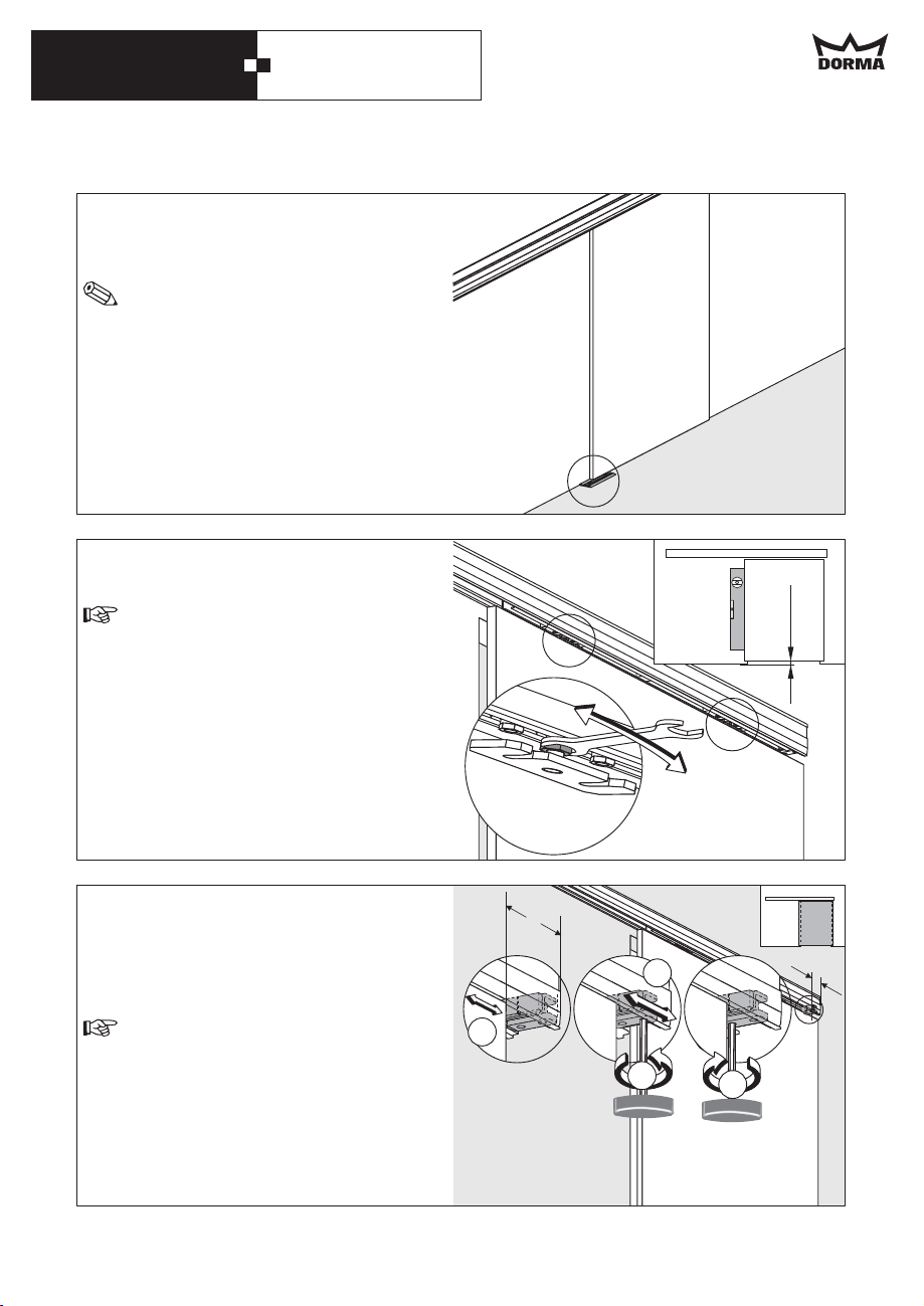
Locate and fix the provided floor guide rail.
Please consider the mounting instructions of
the floor guide.
When adjusting the floor guide you have
to make sure that the door panel runs
smoothly through the floor guide (does
not rub against the floor guide).
Align the door panel with the aid of the
adjustment nuts so that it is level.
The distance between the bottom edge
of the door panel and the floor should
amount to 6 mm, however, it must not
exceed 8 mm.
6mm
Relax the screws of the end stop on the side
where the connections are and move the
door to the desired closed position. Move
the end stop next to the door panel and
screw down tight (5 Nm).
The end stop may only be moved to the
inside by a certain dimension.
875 mm operator => max. 200 mm
1000 mm operator => max. 250 mm
1125 mm operator => max. 300 mm
The end stop must not overlap at the outer
edge.
20
Y
3.
2.
1.
3.
4.
Y
Page 21
DORMA CS 80 MAGNEO
Relax the screws of end stop on the other
side and move the door to the desired
open position. Move the end stop next to
the door panel and screw down tight (5 Nm).
The end stop may only be moved to the
inside by a certain dimension.
875 mm operator => max. 200 mm
1000 mm operator => max. 250 mm
1125 mm operator => max. 300 mm
The end stop must not overlap at the outer
edge.
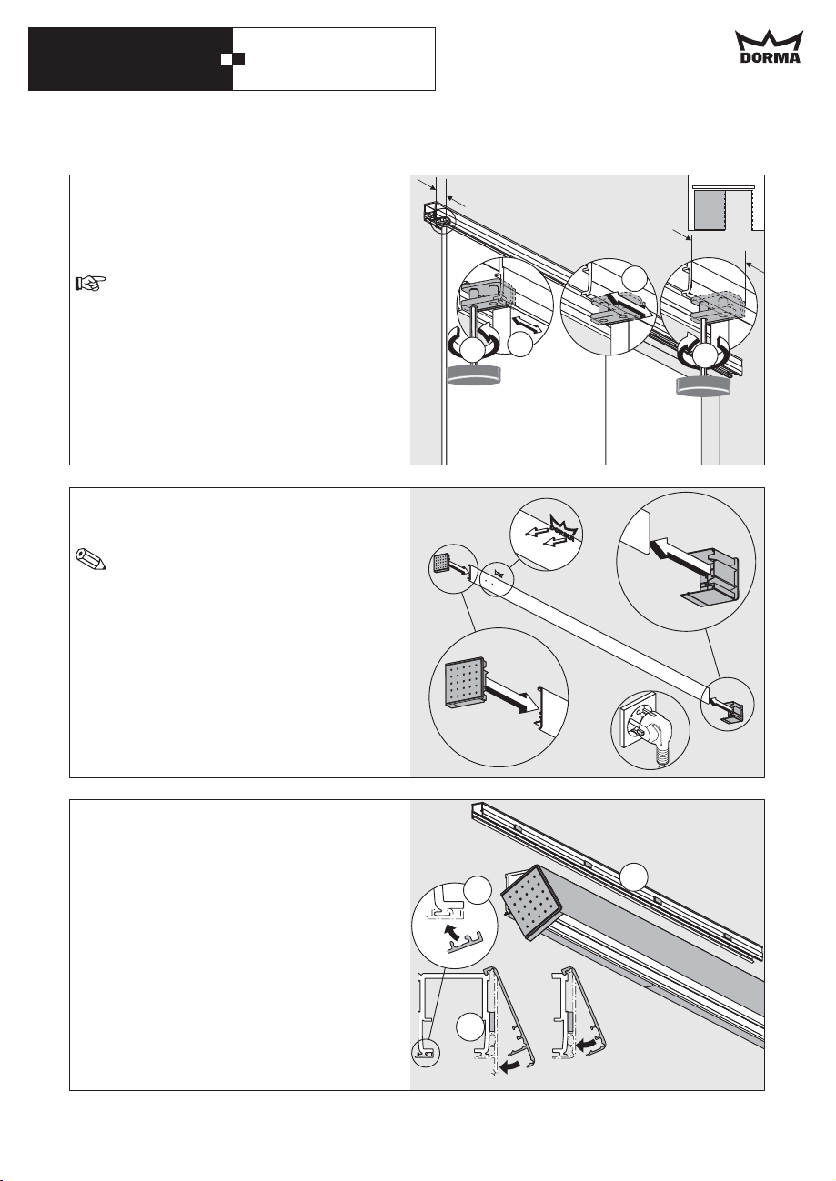
Fix the DORMA logo in the two drill holes.
Insert the end caps into the cover.
Depending on the prevailing structural
conditions, the end caps can either be
cut to length or broke out at the
predetermined breaking points.
Please install radio receivers, program
switches and/or sensors and lay the cables
as indicated in the enclosed instructions.
When the system is operated with a power
plug, plug it in.
Y
Y
3.
2.
1.
4.
1. Adhere the 4 provided pieces of foam
rubber equally onto the operator.
2. Fix the black wall connection profiles at
the bottom of the operator on the side
where it is connected to the wall. Cut
the last profile to length with the aid of
a knife.
3. Place the cover onto the operator and
clip it shut. When using DORMA
MANET single-point fixings, you have to
use the shorter cover (displayed on the
right side).
Continue with the commissioning of the
system as indicated starting from page 31.
3.
2.
1.
21
Page 22
DORMA CS 80 MAGNEO
7. Installation instructions for in-wall mounting
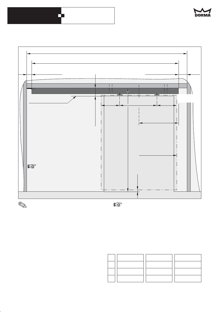
A = at least L + 120 mm
L
min. 50 mm
Bottom edge of lintel
With
wooden door panel:
X
= Door panel height + 75 mm
With glass clamping rail:
X
= Door panel height + 111 mm
With DORMA MANET
single-point fixings
X
= Door panel height + 71 mm
Dimension X has to be measured
at the highest point of the floor
within the movement range of
the door system.
The wall must not be closed before the
system has been installed.
·
The connections should always be on
the side where the door panel is when
the door is in closed position.
·
Dimension stands for the operator
L
length.
·
Dimension indicates the distance
L/4
from the centre of the passage area to
the side of the operator where the
connections are located.
·
The distance between the door panel
and the floor should amount to 6 mm
and must not exceed 8 mm.
mind. 70 mm
min. 70 mm
Side with
C
==
connections
L/4
X
Closed position
6mm
The holes for the cables must be
sufficiently big and must not have sharp
edges.
Please have a look at the table and the
drawing for the dimensions regarding your
operator.
L
L/4
A
C
1750 2000 2250
437.5 500 562.5
mind. 1870
575
mind. 2120
700
mind. 2370
825
22
Page 23
DORMA CS 80 MAGNEO
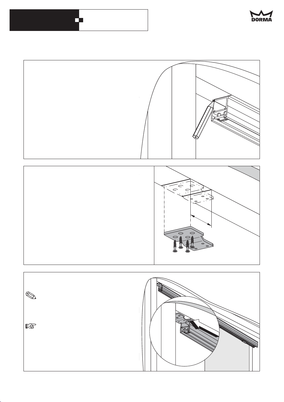
Hold the operator in the desired position and
mark the end of the operator on the side
opposite the connections.
Draw a further line at a distance of 43 mm.
Then position the fixing bracket at the
second line and mark the drill holes.
Drill the holes and fix the fixing bracket with
adequate screws.
Then move the operator over the fixing
bracket as far as it will go.
Make sure to position the operator
correctly, i.e. the side with the
connections must be opposite the fixing
bracket.
Never leave the operator on the fixing
bracket without holding it in position as
this would deform the fixing bracket.
Align the operator so that it is parallel to the
wall.
43
23
Page 24
DORMA CS 80 MAGNEO
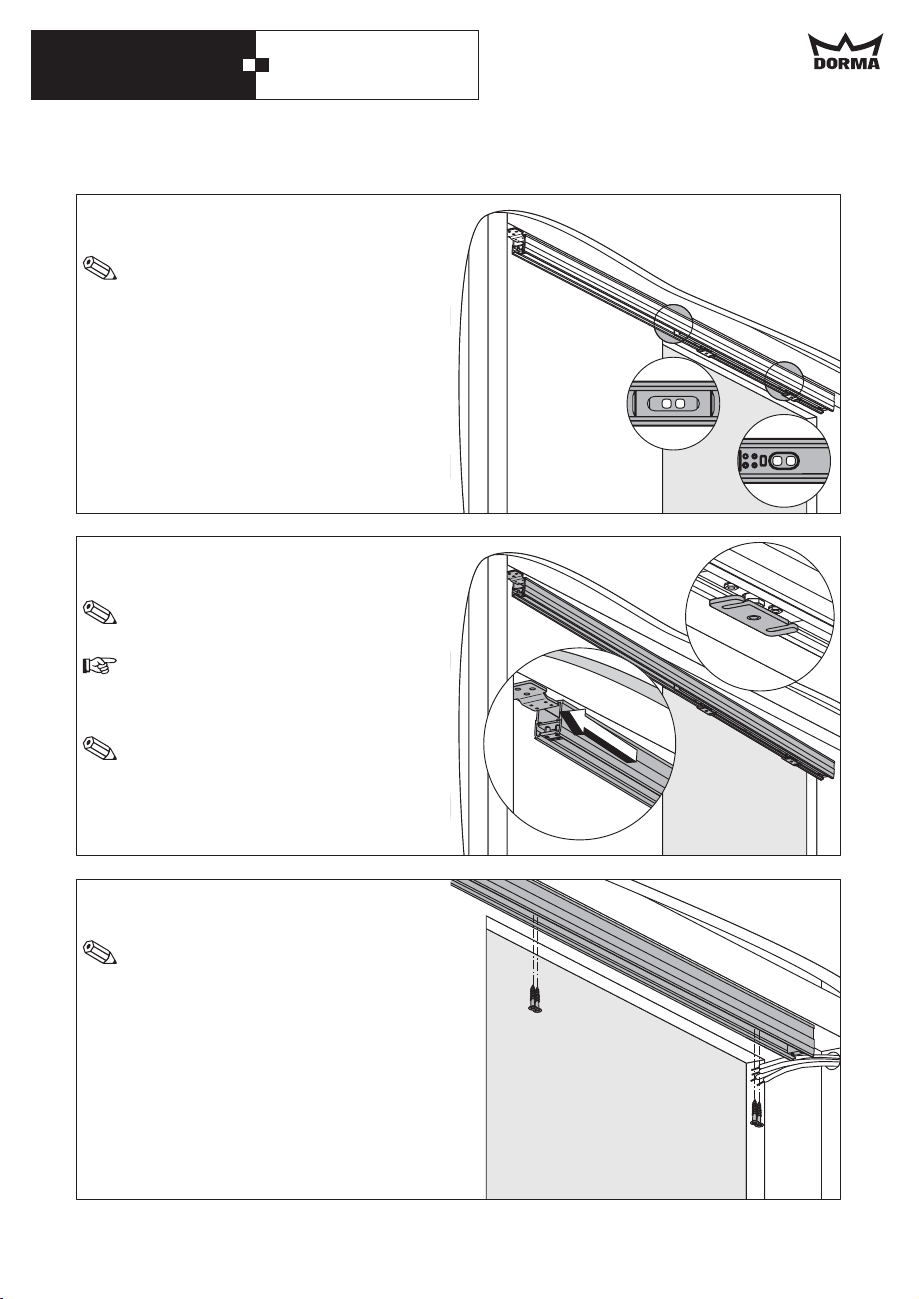
Then mark the fixing holes through the holes
in the operator.
In order to reach all 4 holes, you have to
move the carrier.
Remove the operator and drill fixing holes
with a diameter of 4.2 mm for the supplied
sheet metal screws.
The sheet metal must at least be 2 mm
thick and the subconstruction must at least
carry 240 kg.
Then move the operator over the fixing
bracket as far as it will go.
The side with the connections must be
opposite the fixing bracket.
Never leave the operator on the fixing
bracket without holding it in position as
this would deform the fixing bracket.
The openings of the door panel
suspension have to point to the front as
you cannot turn them following the
installation of the system.
Fix the operator under the cross girder with
the selected screws.
The operator has to be fixed so that it is
exactly level and parallel to the wal.
All connection cables have to be laid in
the close range of the operator at this
point.
The holes for the cables must be
sufficiently big and must not have sharp
edges.
24
Page 25
DORMA CS 80 MAGNEO
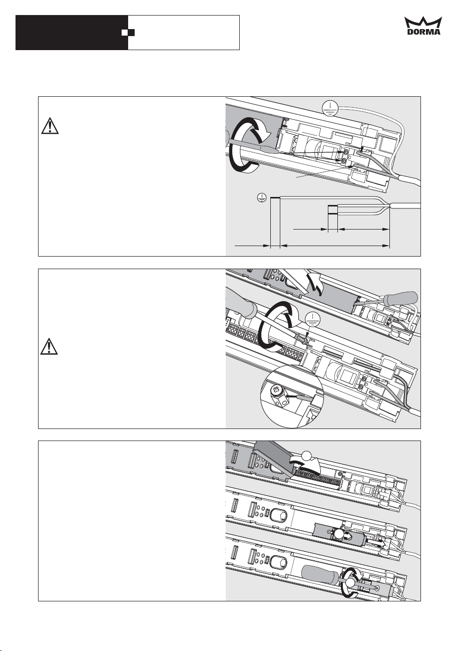
Connection of 230 V permanent power supply
Work on electrical equipment may only
be performed by properly qualified staff
(electricians).
Before starting with the installation,
make sure that the power supply line is
dead (de-energized).
Relax the end stop and move it to the centre
of the system (see page 12, picture in the
middle).
Cut the leads to length, dismantle them and
connect L1 and N to the connection
terminals of the power supply.
Lever out the cover at the control unit
housing with the aid of a screwdriver.
Lay the grounding line through the housing
of the operator as shown in the picture and
connect it to the grounding terminal (PE).
The grounding (PE) has to be connected
in any case.
Connect all external accessories but the
safety sensors.
Please refer to the instructions for the cable
channel on page 29.
6mm
N
6mm
L1
L1
N
35 mm
150 mm
Close the cover of the control unit housing.
Fix and screw down the cover of the power
supply housing.
Move the end stop to the end of the channel
and screw it down thoroughly (see page 13,
picture at the bottom).
1.
2.
3.
25
Page 26
DORMA CS 80 MAGNEO
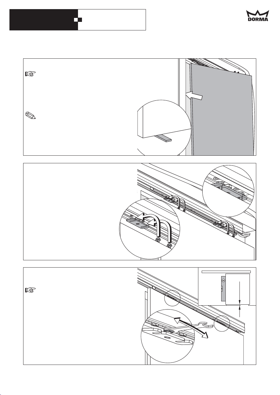
Move the end stop to the end of the channel.
The end stop must not fall out of the
operator.
Place the door panel inside the door frame.
As the door panel is wider than the doorway,
you will have to tilt it.
As it will be difficult to get hold of the
door panel with in-wall mounting, you
should use wooden wedges to help you
to lift the door panel.
Insert the door panel into the door panel
suspension, align it so that it is parallel to
the wall and screw it down.
Align the door panel with the aid of the
adjustment nuts so that it is level.
The distance between the bottom edge
of the door panel and the floor should
amount to 6 mm, however, it must not
exceed 8 mm.
26
6mm
Page 27
DORMA CS 80 MAGNEO
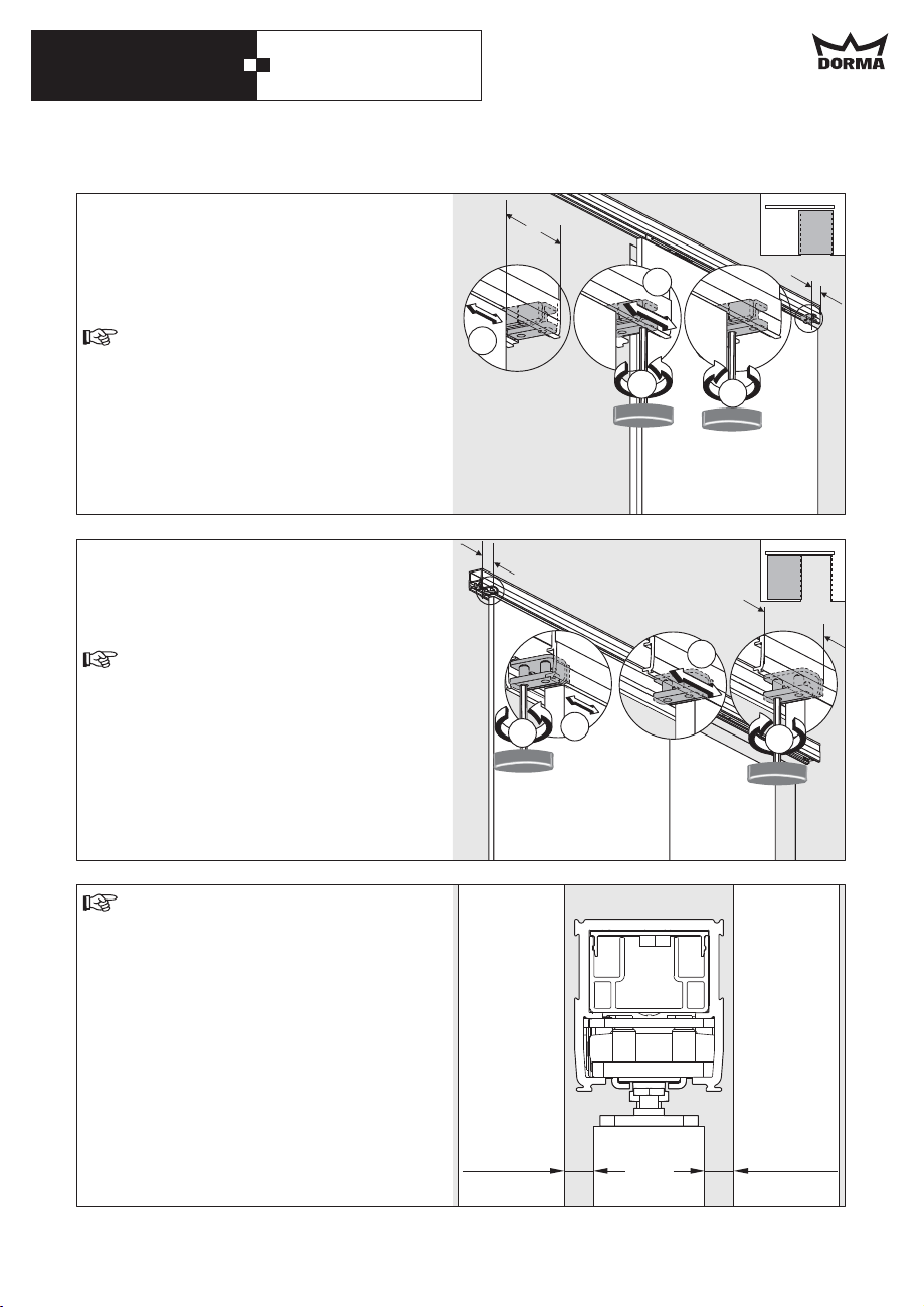
Relax the screws of the end stop on the side
where the connections are and move the
door to the desired closed position. Move
the end stop next to the door panel and
screw down tight (5 Nm).
The end stop may only be moved to the
inside by a certain dimension.
875 mm operator => max. 200 mm
1000 mm operator => max. 250 mm
1125 mm operator => max. 300 mm
The end stop must not overlap at the outer
edge.
Y
3.
2.
1.
3.
4.
Y
Relax the screws of end stop on the other
side and move the door to the desired
open position. Move the end stop next to
the door panel and screw down tight (5 Nm).
The end stop may only be moved to the
inside by a certain dimension.
875 mm operator => max. 200 mm
1000 mm operator => max. 250 mm
1125 mm operator => max. 300 mm
The end stop must not overlap at the outer
edge.
The distance between door panel and
wall must not exceed 8 mm.
The clearance has to be covered with
brushes or similar, if required.
Please install radio receivers, program
switches and/or sensors and lay the cables
as indicated in the enclosed instructions.
Y
Y
Y
3.
2.
1.
4.
Continue with the commissioning of the
system as indicated starting from page 31.
max. 8 mm max. 8 mm
27
Page 28
DORMA CS 80 MAGNEO
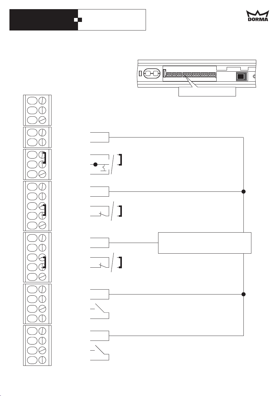
8. Connection diagrams (Only for properly qualified staff!)
In order to facilitate the connection of the
wires, the different terminal blocks can be
removed with pointed pliers.
Connection terminals
94
95
96
not assigned
not assigned
not assigned
Approach in case of a short circuit at the connection terminal
1. Remove short-circuit.
2. Switch mains switch off and on again.
1
3
31
3
34
1
3
15
3
13
1
3
11
3
13
1
3
41
3
+27VDC
GND
Automatic
GND
Permanent
Open
+27VDC
GND
GND
Safety sensor test
+27VDC
GND
GND
Safety sensor test
+27VDC
GND
GND
Program switch (optional)
Remove jumper before a program switch
will be installed
Safety sensor for secondary closing edge
Remove jumper before a sensor
will be installed
Power supply for external
accessories 27 V DC, max. 700 mA
Safety sensor for main closing edge
Remove jumper before a sensor
will be installed
External activator
(e.g. radar motion detector / pushbutton)
28
1
3
42
3
+27VDC
GND
GND
Internal activator inside
(e.g. radar motion detector / pushbutton)
Page 29
DORMA CS 80 MAGNEO
50 mm
6mm
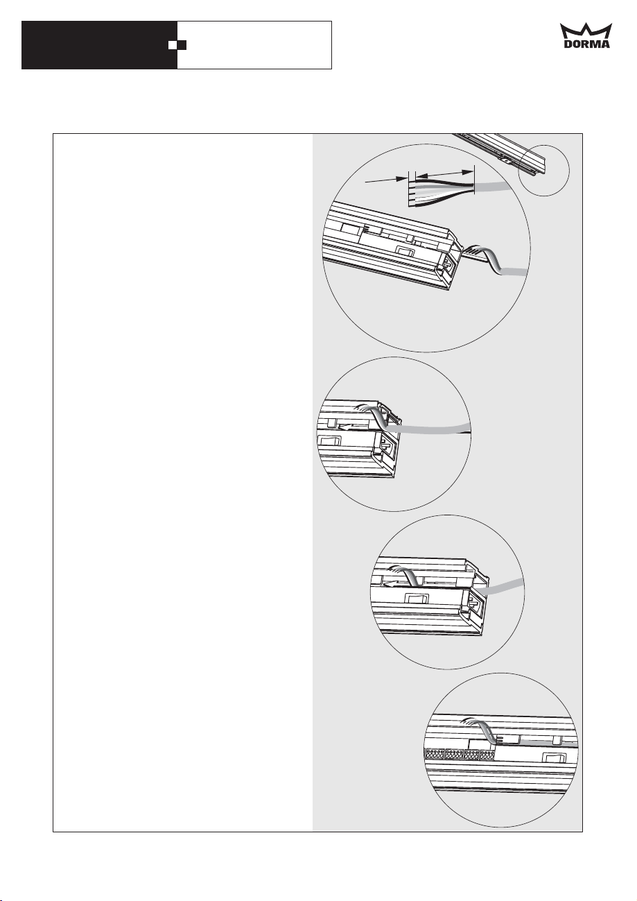
9. Cable channel
The cables for external accessories (sensors,
pushbuttons etc.) have to be laid inside a
cable channel as indicated in the picture.
29
Page 30
DORMA CS 80 MAGNEO
8
7
6
5
4
3
2
1
ON
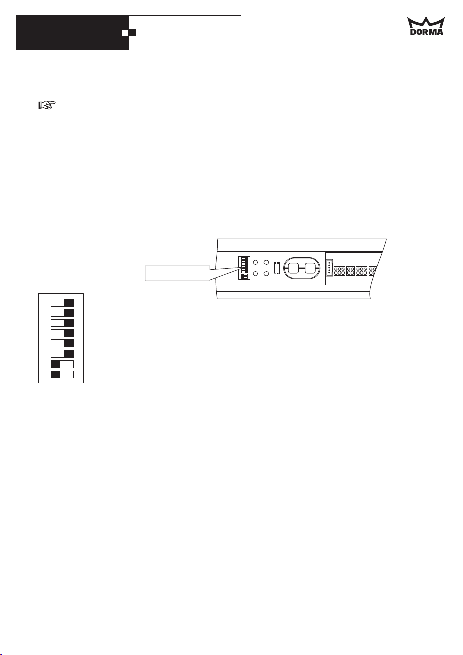
10. Connection of closing edge protection
This work may only be performed by properly qualified staff.
When testable sensors for the protection of the closing edges are connected, the control unit
has to be adjusted to the sensors via the DIP switches.
When a sensor is connected to the main closing edge
Set DIP switch 1 to ON and DIP switch 3 to OFF.
When a sensor is connected to the secondary closing edge
Set DIP switch 2 to ON and DIP switch 3 to OFF.
When sensors are connected to the main and secondary closing edge
DIP switch
8
ON
7
6
5
4
3
2
1
3ON
2ON
1ON
= test high active
OFF
= test low active
=
sensor test for secondary closing edge activated
=
OFF
OFF
sensor test for secondary closing edge deactivated
=
sensor test for main closing edge activated
= sensor test for main closing edge deactivated
30
Page 31
DORMA CS 80 MAGNEO
11. Commissioning
Basic requirements
CS 80 MAGNEO
·
The is completely
mounted.
You can move the door smoothly over
·
the complete movement range.
General information
When you connect the system to the power
supply (plug it in) the green light indicator
blinks and the operator has no function. You
can access the door manually.
In order to make the operator ready for
operation, you have to perform a learning
cycle.
The green LED goes on following the learning
cycle. The is now ready for
operation and operates in Low-Energy-Mode.
This "approach" describes the commissioning
of the standard door system. Accessories and
different operation modes can be adjusted
after the system has been commissioned.
Sensors are connected and adjusted
following the successful commissioning of
the system.
The light indicator (LED) will give you visual
feedback.
The settings stored during the commissioning
of the system can be overwritten by
performing a new commissioning.
Learning cycle
In order to start the learning cycle:
·
·
·
The green LED will blink before the first
learning cycle.
CS 80 MAGNEO
Apart from during commissioning, a
learning cycle has to be performed every
time the position of an end stop has
been adjusted or the weight of the door
has changed.
The door must be open.
The operator must be switched on.
The movement range of the door must
be free of obstacles.
Press and hold the "Reset" button for more
than 3 seconds.
Do not interrupt the learning cycle as
the system currently learns all values it
requires.
During the learning cycle the door will:
Open twice and close again. The LED will
blink green at certain intervals then it will
show a permanent green light.
The CS 80 MAGNEO is now ready for
operation.
How to switch the system from Low-Energyto Full-Energy-Mode
Only authorized staff (authorization on
the part of DORMA required) may
switch the CS 80 MAGNEO to FullEnergy-Mode. As there are higher forces
in Full-Energy-Mode, the closing edges
have to be protected by safety sensors.
Therefore we do not explain how to switch
the system to Full-Energy-Mode in these
instructions.
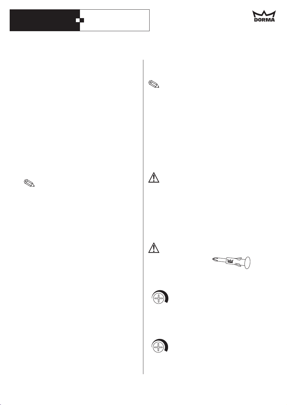
Only use the enclosed red screwdriver
to perform potentiometer adjustments!
Speed adjustment
speed /
Geschwindigkeit
The maximum speed depends on
the weight of the door panel. You
can reduce the speed with the aid
of the potentiometer (infinitely
variable).
Adjustment of hold-open time
The door will close automatically
hold open time /
Offenhaltezeit
on expiry of the adjusted holdopen time following it has
reached "open" position. You can
adjust the hold-open time
infinitely from 5 to 30 seconds
with the aid of the potentiometer.
31
Page 32
DORMA CS 80 MAGNEO
8
7
6
5
4
3
2
1
ON
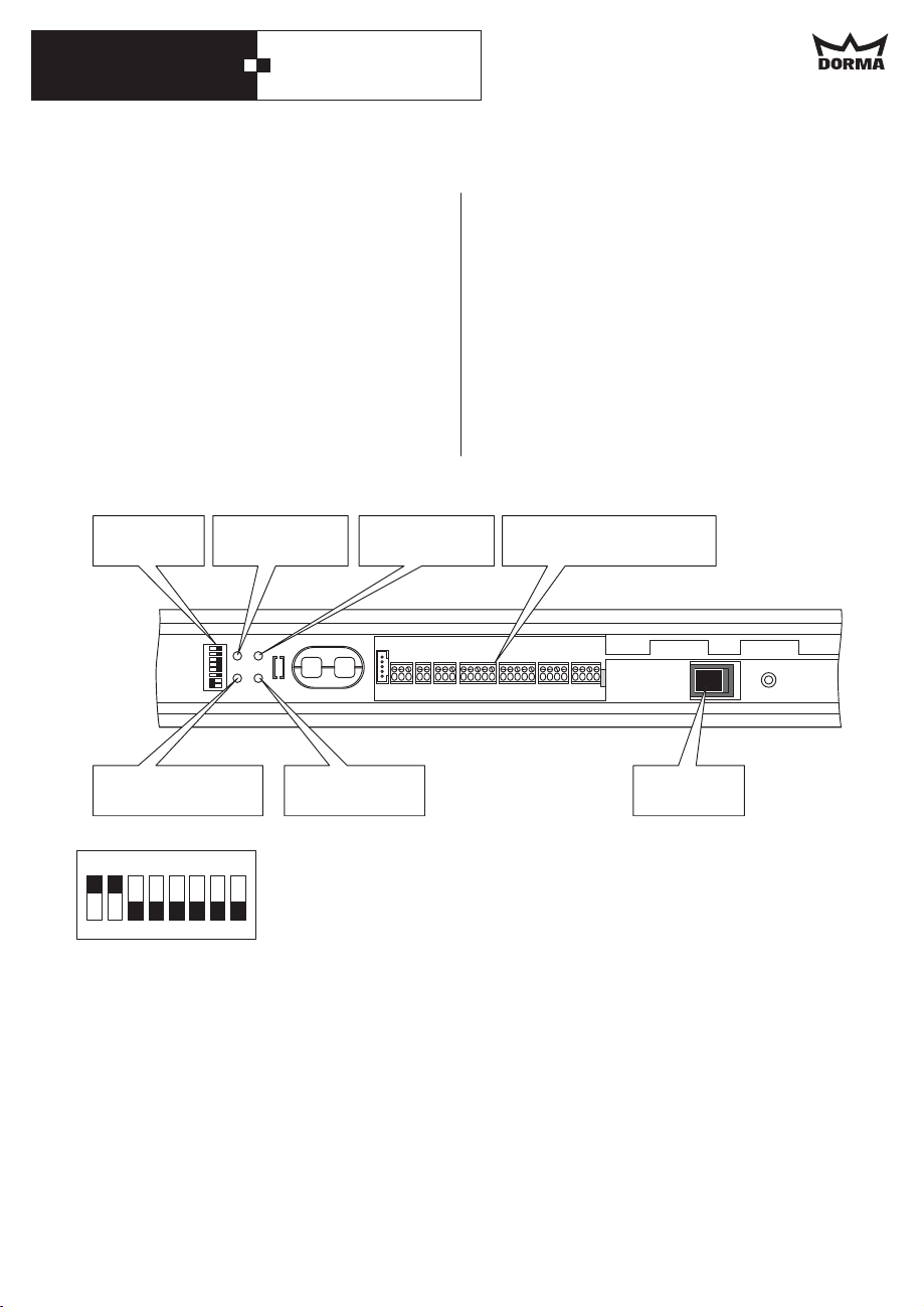
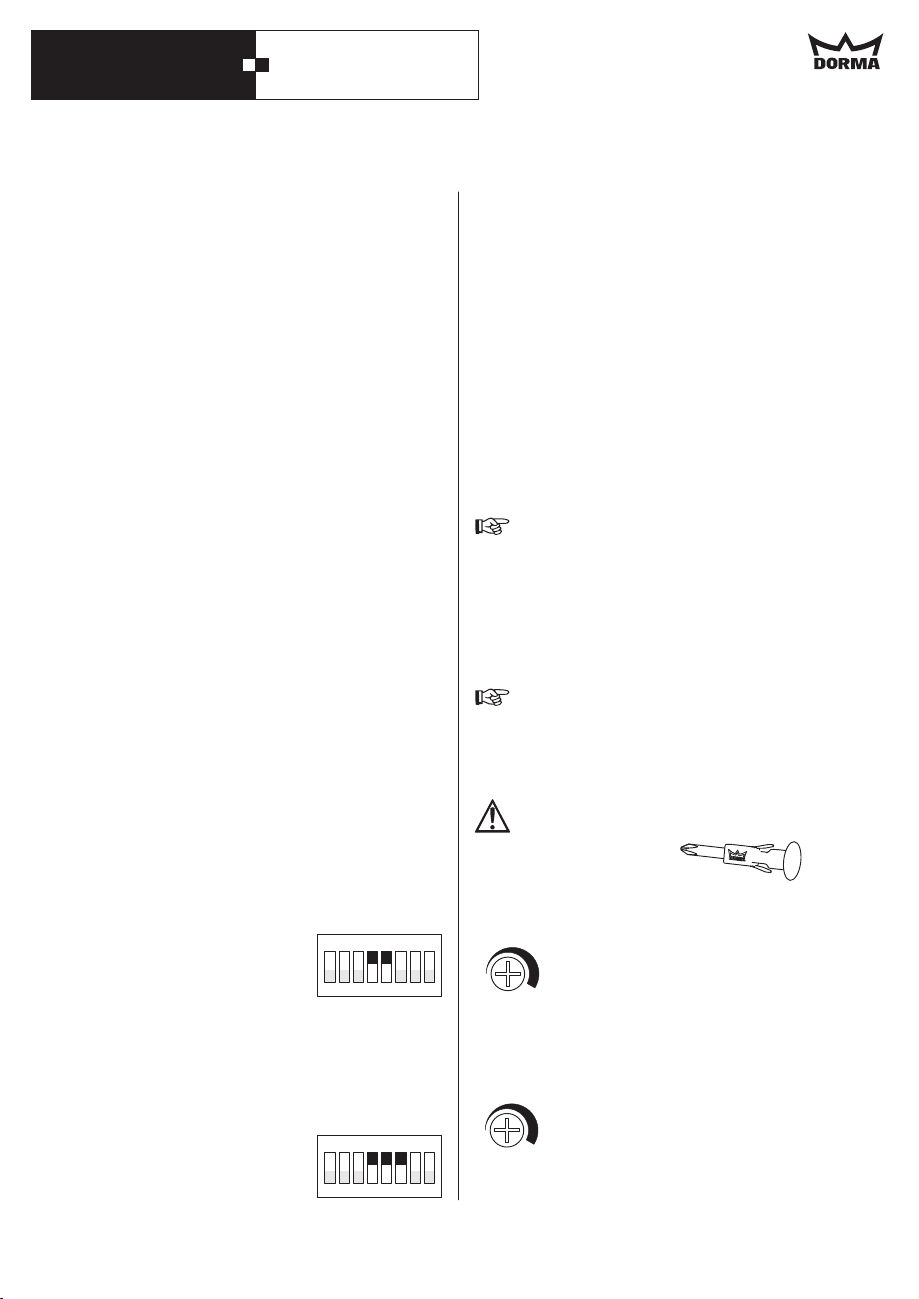
Permanent Open Function via double-click
This function can only be adjusted when a
pushbutton is connected.
In order to activate this function, DIP
switches 4 and 5 at the control unit have to
be set to ON position.
Opening/closing via pushbutton
This function is only available with
pushbutton or Push & Go Function.
In order to activate it, DIP switches
4, 5 and 6 have to be set to "ON" position.
DIP switch
LED
light indicator
Reset button
Start learning cycle
Potentiometer
speed
Potentiometer
hold-open time
Closing force
In case the door does not close properly due
to the door seals, you can increase the force
with which the operator presses the door
against the seal.
In order to do so, set DIP switch 7 to ON
position.
Connection terminals for
external accessories
Mains switch
ON
DIP switch settings
You can activate different inputs at the connection terminals via these
switches and thus adjust different operation modes.
1
2
3
5
4
No function
8
OFF = Reduced closing force ON = Enhanced closing force
7
OFF = Automatic Function activated ON = Permanent Open Function activated
6
OFF = External motion detector activated ON = External pushbutton activated
5
OFF = Internal motion detector activated ON = Internal pushbutton activated
4
OFF = Test low active ON = Test high active
3
OFF = Sensor test at secondary closing edge deactivated
2
8
7
6
ON = Sensor test at secondary closing edge activated
OFF = Sensor test at main closing edge deactivated
1
ON = Sensor test at main closing edge activated
32
Page 33
DORMA CS 80 MAGNEO
12. Operating instructions
1. Opening the door in AUTOMATIC
Function
When the system is delivered, the
CS 80 MAGNEO
Function. Depending on the installed
accessories, the door can be opened in
different ways.
Push & Go
As soon as the door is moved manually into
opening direction by approximately 10 mm,
the operator automatically moves the door
panel further in the desired direction.
The door closes automatically.
Pushbutton:
Following the activation of the pushbutton
(e. g. wall-mounted pushbutton or radio
transmitter) the operator opens and closes
the door.
Sensors:
Where presence sensors (radar motion
detectors or similar) are connected, the door
opens automatically as soon as a person
approaches the door system.
The door closes automatically.
PERMANENT OPEN via double-click
When this function is activated, the door can
be opened permanently by double-clicking
the pushbutton. In order to close the door,
a further double-click on the pushbutton is
required.
To activate this function
set
DIP switch
to position.
ON
Opening/Closing via pushbutton
As soon as you push the button or move the
door manually the door will open. When you
push the button for a second time or move
the door panel by hand, the door will close.
To activate this function
set DIP switch
to position.
ON
is adjusted to AUTOMATIC
ON
4 and 5
1
2
3
4
ON
4, 5 and 6
1
2
3
4
5
5
Express-Function
The door can be moved manually along its
operational path without extra resistance.
When the maximum speed is exceeded, the
operational resistance will increase in line
with the speed by which it is exceeded.
As soon as the user has released the door
panel, the operator will softly slow it down to
maximum speed. This function is activated
during all opening and closing cycles.
2. In the event of a power failure
In the event of a power failure, the door can
be opened and closed by hand.
However, in this case the system does
not brake the door panel, which means
that the user has to move (hold) it all
the way by hand.
As soon as the voltage returns, the operator
will automatically perform a position
initialization.
During this position initialization, the
movement range of the door has to be
free of obstacles.
3. Adjustments
Only use the enclosed red screwdriver
to perform potentiometer adjustments!
Speed adjustment
speed /
Geschwindigkeit
The maximum speed depends on
the weight of the door panel. You
can reduce the speed with the aid
8
7
6
of the potentiometer (infinitely
variable).
Adjustment of hold-open time
The door will close automatically
hold open time /
Offenhaltezeit
on expiry of the adjusted holdopen time following it has
reached open position. You can
adjust the hold-open time
infinitely from 5 to 30 seconds
8
7
6
with the aid of the potentiometer.
33
Page 34
DORMA CS 80 MAGNEO
4. Closing force
In case the door does not close properly due
to the door seals, you can increase the force
with which the operator presses the door
against the seal.
In order to do so, set DIP switch 7 to "ON"
position.
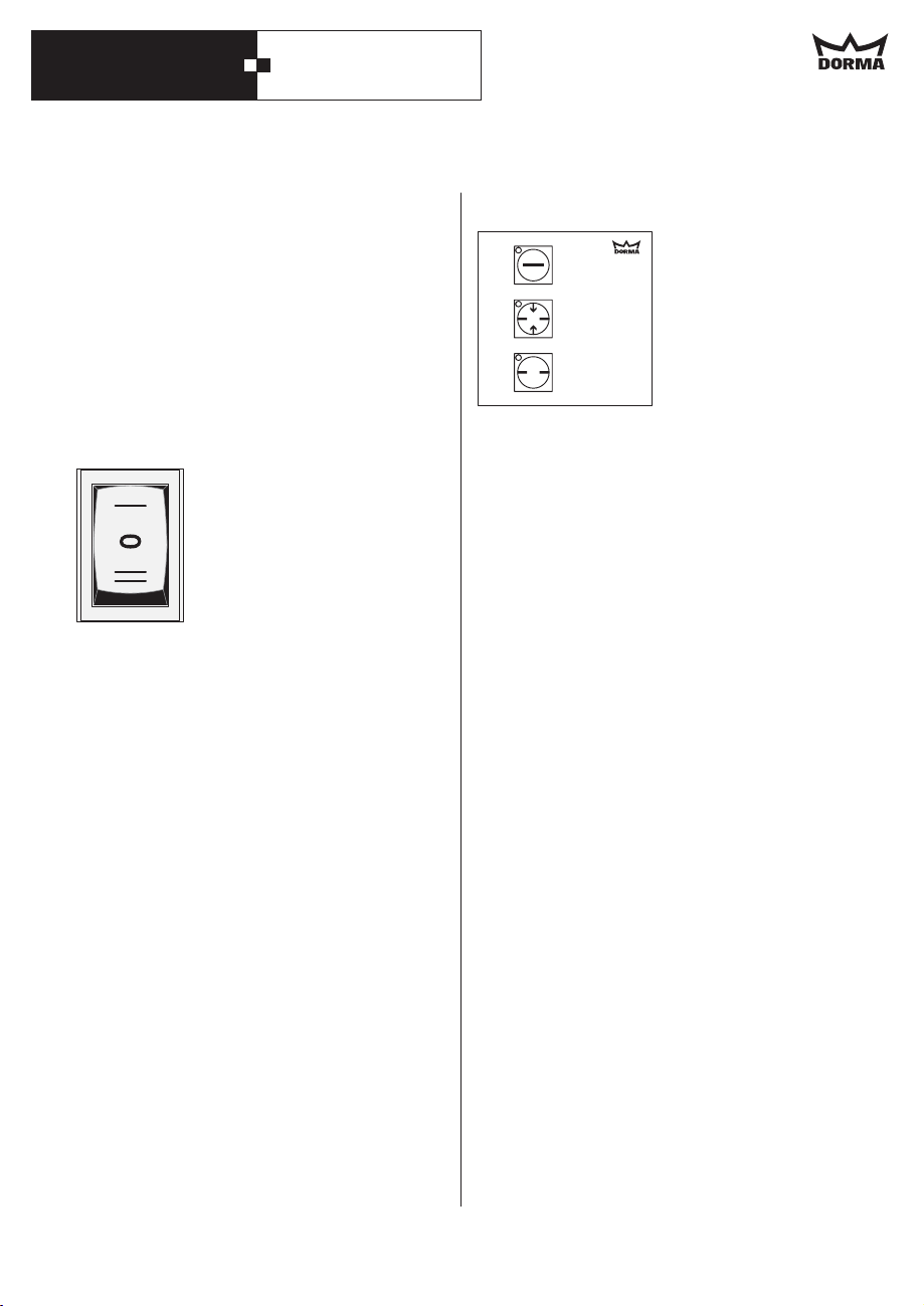
5. Internal program switch (optional)
The internal program switch (if available) is
installed in the lateral cover on the side
where the door is when "closed".
AUTOMATIC
OFF
PERMANENT OPEN
Changing the operation mode
In order to change the operation mode, just
adjust the program switch to the desired
function.
6. Program switch EPS-S3 (optional)
1
2
OFF
AUTOMATIC
3
PERMANENT OPEN
Changing the operation mode
The EPS-S3 is secured via an individually
adjustable 4-digit code.
1. Unlock the EPS-S3 by entering in the
code.
Original setting =
1-1-1-1.
The last 4 digits always count.
In case you entered an incorrect code,
just retype the correct code.
·
EPS-S3
The is unlocked
·
The LED for the current operating mode
blinks.
2. Adjust the desired operation mode by
activating the respective button.
·
The LED of the selected operation mode
lights up.
34
The EPS-S3 locks automatically 1 minute
after its last activation.
Power failure
Following a power failure, the EPS-S3 is
adjusted to the operation mode that has
been activated before the power failure.
Page 35
DORMA CS 80 MAGNEO
13. Commisssioning and maintenance according to DIN 18650-2, 5.1-5.4
According to DIN 18650, the following points have to be observed:
An inspection and acceptance test according to the below-mentioned checklist has to be
·
performed before the first commissioning of the system by trained staff (trained by
DORMA).
·
Regular maintenance and inspections have to be performed (at least once a year) under
consideration of our specifications for the CS 80 MAGNEO by properly trained staff.
·
Documentation of the results in accordance with DIN 18650-2 paragraph 5.1-5.4.
The facility operator has to keep the properly filled-out checklist according to our
specifications for at least 1 year.
Checklist (start-up test, maintenance, regular inspections) according to DIN 18650-2,
paragraph 5.1-5.4
The system has been installed properly in accordance with the instructions of the
manufacturer.
The door panels run smoothly/have been readjusted (if required).
The door works properly (check the opening and closing cycle respectively).
Function of installed activators like radar motion detectors, pushbuttons or remote
controls has been checked.
The contactless safety equipment (safety sensors), if installed, has been checked for
proper function.
Effective safety equipment has been installed to avoid or protect danger spots between
certain parts of the door system and between the door and its structural environment (like
for example safety clearances or the protection of the secondary closing edges).
Test badge has been fixed.
The inspection and maintenance work has been documented.
CS 80 MAGNEO
The has to be switched off and secured against unintended and unauthorized
switching on before performing maintenance work (cleaning or maintenance).
Care
Only use commercial cleaning agents to clean the operator.
Scrubbing cleansers might damage (scratch) the surface of the operator
.
35
Page 36
DORMA CS 80 MAGNEO
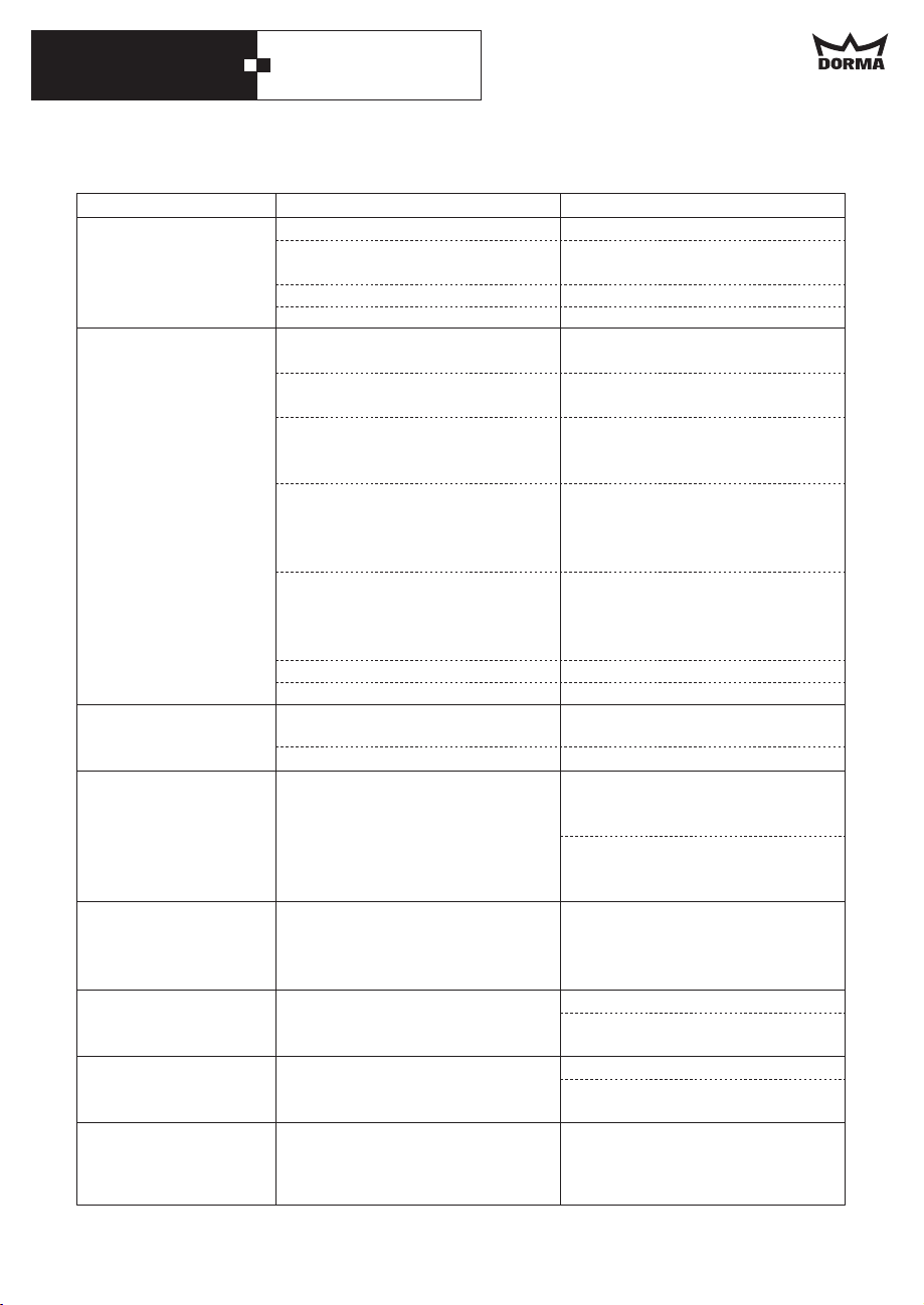
11. Troubleshooting instructions
Malfunction
The door does not
respond.
The green LED light
indicator is off.
The door does not
respond.
The green LED light
indicator is on.
The green LED light
indicator blinks at
certain intervals.
The door stops during
a cycle.
The door moves
beyond the adjusted
open or closed
position.
The red LED light
indicator illuminates
permanently.
The red LED light
indicator blinks twice
at certain intervals.
The red LED blinks 3
times at regular
intervals.
Possible cause
No power supply.
Loose cable connections.
Damaged power cord.
Damaged power plug.
The program switch is set to
(OFF).
The program switch is set to
(Permanent Open).
The door has been adjusted to
Permanent Open Function via
double-click.
The safety sensors at the door
are activated (there is something
within the detection range of the
sensor).
Damaged sensor cable.
No safety sensors are connected.
The operator is defective.
The learning cycle has not been
performed properly.
The operator is defective.
The door does not run smoothly.
The corresponding end stop has
shifted its position.
Defective control unit.
Defective control unit.
The power mode switch of the
door has been switched to
another position.
Remedy
Switch on mains switch.
Connect cable connections
thoroughly.
Replace power cord.
Replace operator.
Set the program switch to the
[0]
desired function.
Set the program switch to the
[II]
desired function.
Close door via double-click.
Remove obstacles. Adjust safety
sensors if required.
Check and replace cables if
required.
Check and replace jumpers if
required.
Terminals must be bridged.
Replace operator.
Restart learning cycle (Page 31).
Replace operator.
Check movement range and
remove cause for unsmooth
running.
Check guide rail and floor guide
for dirt or wear and clean or
replace if required.
Readjust end stop and tighten
screws.
Start learning cycle (Page 31).
Switch mains switch off and on.
Replace operator.
Switch mains switch off and on.
Replace operator.
Switch mains switch off and on.
36
Page 37
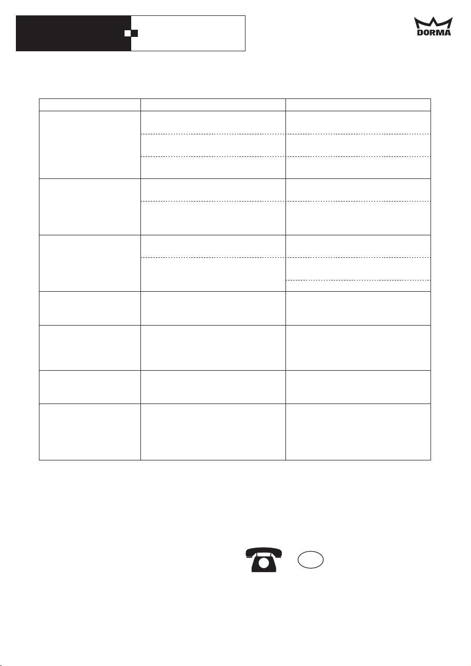
DORMA CS 80 MAGNEO
Malfunction
The red LED blinks 4
times at regular
intervals.
The red LED blinks 5
times at regular
intervals.
The red LED blinks 6
times at regular
intervals.
The red LED blinks 10
times at regular
intervals.
Humming noise while
door is in end
position.
The door panel
vibrates when moving.
Possible cause
Testable safety sensors are
defective.
Damaged sensor cable.
DIP switches 1 to 3 are not set
correctly.
Incremental encoder or cable of
incremental encoder is defective.
The opening width is adjusted
incorrectly.
There is an obstacle within the
door s movement range.
The opening width has been
adjusted incorrectly.
Stator or cable of stator is
defective.
Short circuit at the terminal
connection.
Inappropriate end position of
door panel.
The guide mechanism is under
tension.
Remedy
Check and replace safety sensors
if required.
Check and replace cables if
required.
Check settings of DIP switches
and readjust if required.
Switch mains switch off and on.
Replace operator.
Readjust opening width
(end stops).
Start learning cycle (Page 31).
Remove obstacles from
movement range.
Readjust opening width (end
stops).
Start learning cycle (Page 31).
Switch mains switch off and on.
Replace operator.
1. Remove the short circuit.
2. The operator has to be
switched off and then on with
the aid of the mains switch.
Shift end stop by at least 2 mm.
Start learning cycle (Page 31).
Readjust the door panel
connection and the floor guide if
required. Turn the nuts several
times in order to fix the door
panels.
Operating cycle indicator
When you press the "Reset" button on the control unit for a short time, the door will open. In
case the LED light indicator lights up for one second (yellow light), the system has performed
more than 200,000 cycles.
You should contact the Service Department in order to have the system checked.
Please call the following number in case
of technical problems or further questions:
In case a defective operator has to be replaced, please contact your authorised dealer at the
respective point of purchase with the respective proof of purchase. However, you have to
consider that the complete basic operator including carriers has to be returned
GB
01462 477 602
37
Page 38
DORMA CS 80 MAGNEO
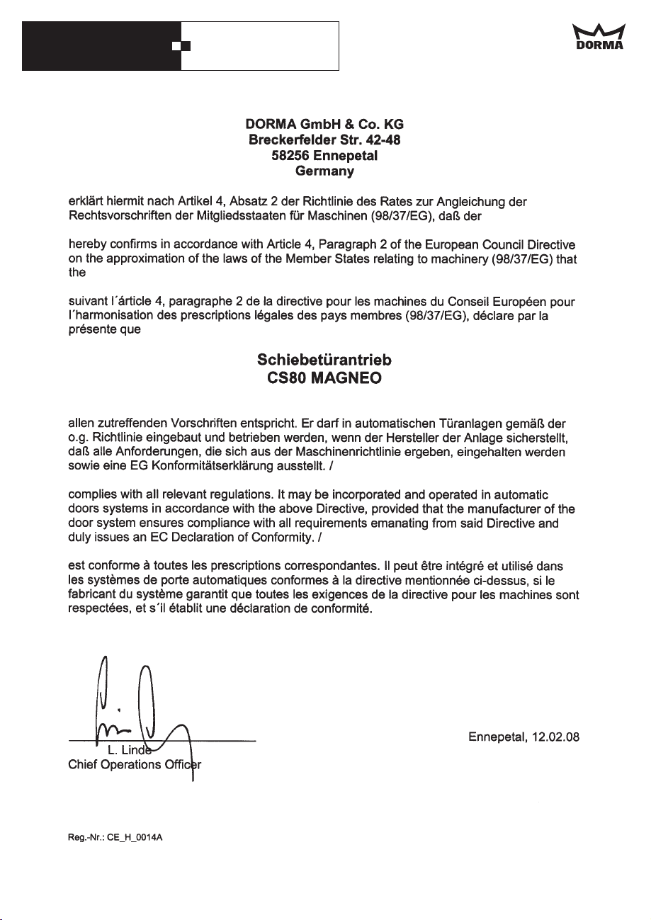
Manufacturer's declaration
38
Page 39
DORMA CS 80 MAGNEO
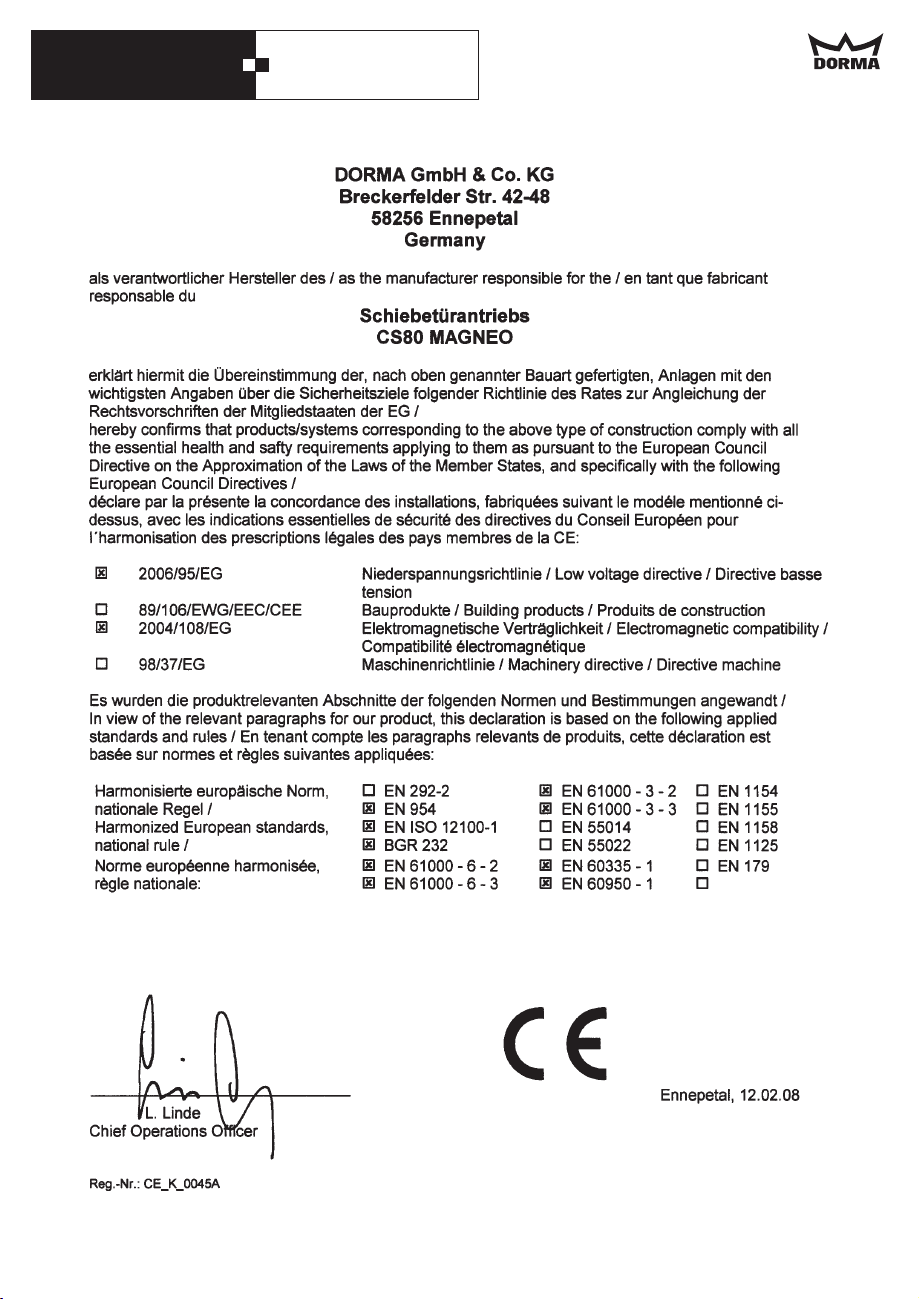
Declaration of conformity
39
Page 40
DORMA CS 80 MAGNEO
Door Control
Automatic
www.dorma-magneo.com
Glass Fittings and
Accessories
Security/Time and
Access (STA)
Movable Walls
DORMA GmbH + Co. KG
DORMA Platz 1
D-58256 Ennepetal
Tel. +49 2333/793-0
Fax +49 2333/793-495
WN 057452 45532, 07/09,·Subject to change without notice
 Loading...