

Page 1

DORMA
CD 80
Swing Door Operator
CD 80
SWING DOOR OPERATOR
INSTALLATION INSTRUCTIONS
Distributed by:
DORMA AUTOMATICS, Inc. 924 Sherwood Drive Toll-Free: 877-367-6211 DL2862-010
Lake Bluff, IL 60044 Fax: 877-423-7999 Jan. 2007
Page 2
DORMA
CD 80
Swing Door Operator
DORMA
1
DORMA AUTOMATICS, Inc. 924 Sherwood Drive Toll-Free: 877-367-6211 DL2862-010
Lake Bluff, IL 60044 Fax: 877-423-7999 Jan. 2007
0
Page 3
2
1
3
1-2 mm
3
2
1
CD 80
Swing Door Operator
DORMA
2
DORMA AUTOMATICS, Inc. 924 Sherwood Drive Toll-Free: 877-367-6211 DL2862-010
Lake Bluff, IL 60044 Fax: 877-423-7999 Jan. 2007
2
1
3
Page 4
DORMA
CD80
Swing Door Operator
4a
4b
3
DORMA AUTOMATICS, Inc. 924 Sherwood Drive Toll-Free: 877-367-6211 DL2862-010
Lake Bluff, IL 60044 Fax: 877-423-7999 Jan-2007
E-mail: [email protected] Subject to change without notice
Page 5
min. 15°
90°
1
2
3
5
6
4
1
2
1
2
2
CD 80
Swing Door Operator
DORMA
4
DORMA AUTOMATICS, Inc. 924 Sherwood Drive Toll-Free: 877-367-6211 DL2862-010
Lake Bluff, IL 60044 Fax: 877-423-7999 Jan. 2007
5
6
6
7
8
9
10
11
Page 6
1
1
2
2
3
2
1
4
3
90°
3
CD 80
Swing Door Operator
DORMA
5
DORMA AUTOMATICS, Inc. 924 Sherwood Drive Toll-Free: 877-367-6211 DL2862-010
Lake Bluff, IL 60044 Fax: 877-423-7999 Jan. 2007
12
13 14
Page 7

1. Technical data
Applications for single-leaf standard doors
Door leaf width 27” [700 mm] - 48” [1200 mm]
(depending on door weight;
see diagram)
Door leaf weight, max. Up to 330 lbs (depending on
door width; see diagram)
Fixing positions Top jamb xing on the hinge (pull)
side
Top jamb xing on the opposite
hinge (push) side
Frame reveal depth With slide channel (all xing
options) -30 mm to 30 mm
* The standard arm is only provided for top jamb xing on the
opposite hinge (push) side. Application of the standard arm increases
the forces of the door so that manual operation is still possible, but not
very comfortable. Where a standard arm is to be installed, DORMA
recommends use of an appropriate activator rather than the
Push&Go function.
Within the door opening angle of 0°-15°, static powers may exceed
150 N. Where the door is protected via force limitation, dynamic
powers according to DIN 18650 must be complied with and an
additional contactless protection must be installed if required.
Permissible door widths and weights
Technical data of the drive unit
Closing force Within BHMA/ANSI Standards
Door closing force Within BHMA/ANSI Standards
Dimensions H 2 3/4” [70 mm]
L 26” [660 mm]
D 3 1/2” [90 mm]
Weight incl. mounting plate 19 lbs [8.5 kg]
Opening angle 0° to 110°
Temperature range 0° to 40°
Relative humidity up to 93%
Power supply data 115 V, 50/60 Hz
Power supply for external 24 V DC 600 mA
accessories
Class of protection IP 20
UL 325 type-approved
Compliant with Low Voltage
and EMC Directives
Manufactured to
ISO 9000:2000
27”
31” 35” 40” 43”
48”
Door width (in)
Door weight (lb)
0
340
300
220
260
176
130
45
90
Permissible
door specications
CD 80
Swing Door Operator
DORMA
6
DORMA AUTOMATICS, Inc. 924 Sherwood Drive Toll-Free: 877-367-6211 DL2862-010
Lake Bluff, IL 60044 Fax: 877-423-7999 Jan. 2007
Adjustable parameters of the travel path
Opening time adjustable 3 s to 6 s
Closing time adjustable 3 s to 10 s
similar to door closer
Hold open time adjustable 0 s to 30 s
Latching speed adjustable
Wall blanking adjustable
Opening angle adjustable
Angle for extende hold-open
function adjustable
Delayed opening for locking
mechanism adjustable
Standard funtion programs and special functions
Functions cia programs switch OFF
Automatic
Permanent Open
Special functions
included as standard Push & Go
Power Assist Mode
Extended
Hold-Open function
Optional Airlock function
special funtions Timed airlock function
(additional accessories Flip-op-function
required) Night-bank function
Door closer funtion under cut-out conditions
Prepared for connection of the following accessories
Softline slide channel
Door locking devices
Electric strikes (fail-safe/fail-secure principle)
Access control system
Activators (puch button, radar motion detector,
DORMA AutoSwitch...)
Radio remote control
External program switch
standard optional
Page 8
2. General
General information
Working on electrical equipment must only be performed
by trained and properly qualied electricians.
Electrical installaion:
· The electrical supply installaion (115 V AC ± 10%,
50/60 Hz) is to be provided by others.
· The operator is supplied from the factory
with a two-pole-and-earth plug.
· If the operator is to be xed to a metallic
door leaf, the door leaf must be properly
grounded/earthed.
· This should supply a two-pole-and-earth socket
prtected by a 10 a fuse.
Maintenance and care:
The door set shoud be inspected by an
engineer prior to the rst start-up and
then checked and maintained in
accordance with requirements, with a
minimum inspection rhythm of once a
year.
Ensure that the unit is properly
disconnected fom the power source
when carrying out cleaning and
maintenance work.
4
3
2
1
0
3. Installation instructions
Fixing procedure
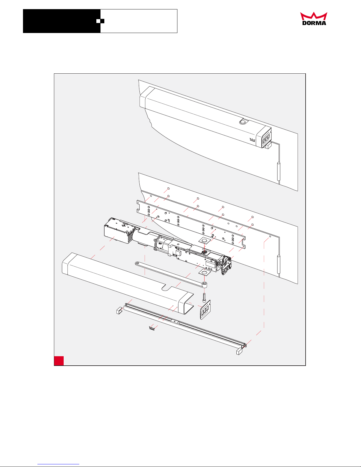
Overview and exploded drawing
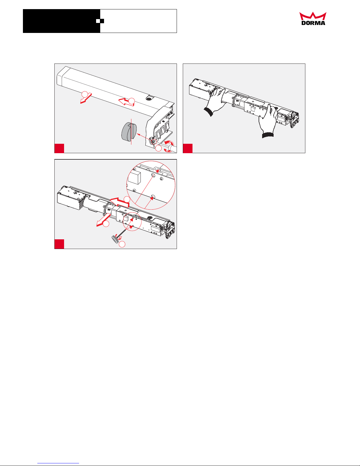
Remove cover
The cover is grounded (earthed) with a ground (earth)
cable.
The cover is latched and held by a screw fastener remove
the screw fastener
Move the cover approx. 1/8” [2 mm] away from the switch
side to unlatch and remove. Disconnect the ground cable.
Only Grip the operator at the positions indicated in the
illustration.
Unscrew the drive unit from the mounting plate.
Structural conditions
The following accessories are available to accommodate
special structural conditions:
A
B
8
7
6
5
Fixing the mounting plate
If the frame comprises steel proles, drill a pilot hole for a
10-32 screw and then tap to the required thread size.
In the case of timber frames, use wood screws
(included in standard supply)
Slide channel operator for:
- Top jamb xing on the pull side - Operator type G
- Top jamb xing on the push side - Operator type B
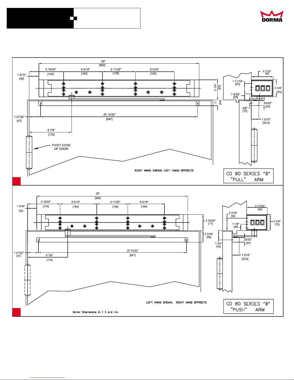
Fixing dimensions
Please note the dierent weights governing the xing
modes.
Mark the holes (8) for installing the mounting plate in
accordance with the dimensional data, then drill and tap
threads as necessary. Mark the holes (2) for xing the slide
channel or the standard arm in accordance with the
dimensional data. Drill holes and tap threads as necessary.
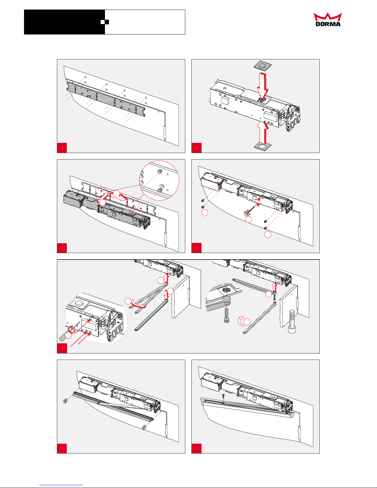
Fix mounting plate.
Fitting the spindle cover
Secure the spindle cover in position so that the hole is
centrally located over the spindle to which the arm is tted.
Mounting the operator (drive unit)
Place the drive unit on the mounting pins and push in the
direction of the switch unitl latched in position. Secure the
drive unit using the captive screws and the four additional
screws (1/4-20 x 3/8”)
CD 80
Swing Door Operator
DORMA
7
DORMA AUTOMATICS, Inc. 924 Sherwood Drive Toll-Free: 877-367-6211 DL2862-010
Lake Bluff, IL 60044 Fax: 877-423-7999 Jan. 2007
For slide channel arm, proceed as per
gs.
Mounting the slide channel arm
The self-locking screw must only be used once! If
the screw has to be undone for repair or maintenance
work, it must be replaced by a new self-locking screw
(see spare parts list).
Mounting the slide channel
Adjusting the hydraulic settings
The CD 80 exhibits dierent operating
characteristics when used as a door closer (without
electronic control) or as an AUTOMATIC operator.
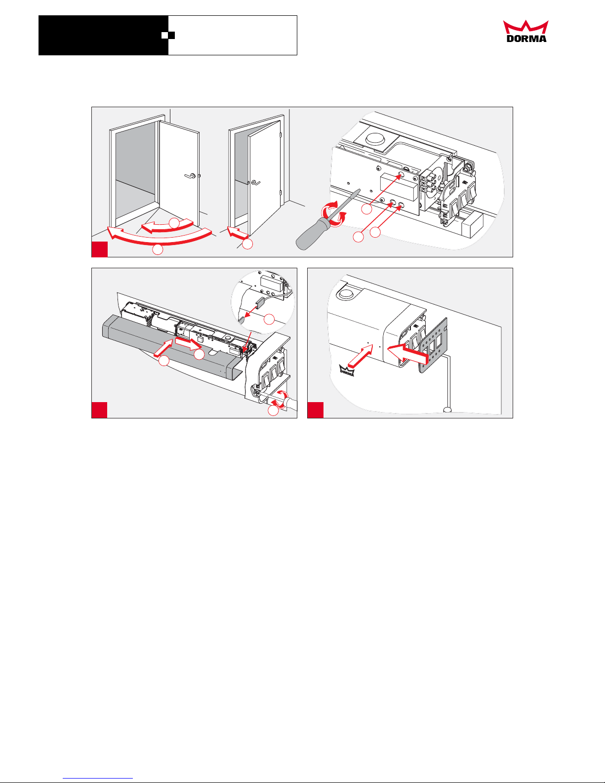
Close all valves (3) by turning clockwise.
Secure the slide channel arm with the self-locking
screw to the operator spindle
If necessary, turn the closer spindle using the slide
channel arm in order to enable it to be installed
with the correct preload.
Fix the slide channel to the door and t the slide
channel end covers.
Open the door slightly and t the slide channel arm
to the slide block in the slide channel.
9910
10
11
11
12
Page 9
DORMA
Adjusting the closing speed from 7° to 0° (latching
)
When used as an automatic operator, it requires
longer closing times. This must be taken into
account when adjusting the settings.
1. Closing speed for the sweep range from 110° to 0°
2. Closing speed for the sweep range from 110° to 25°
Do not open valve 3 too wide as otherwise the door
will not open properly.
After a few automatic door cycles, re-check the
hydraulic functions and adjust as necessary.
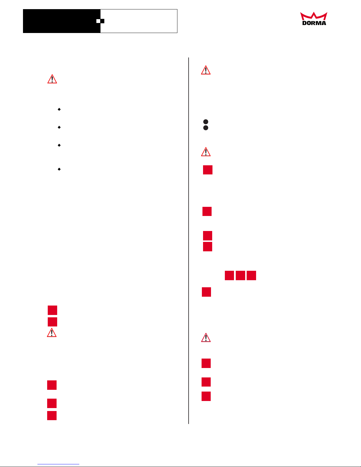
Fit ground/earth cable.
Fit switch trim.
Open the door manually to its fully opening angle
(90° - 110°) and then release.
Slowly open valve 1 (110° - 0°) until the closing
cycle of the door takes place at the required speed.
If the door closing cycle needs to begin at a higher
speed, see 2.
Open the door manually to its fully opening angle
(90° - 110°) and then release.
Mount cover and push in direction of switch until
latched in position. Tighten screw fastener (turn 90°).
Clip DORMA logo in place.
action
The latching action may need to be
adjusted to ensure that the door engages properly in
the lock. Only adjust if the door does not engage
properly in the lock.
Open the door manually to half the opening angle
and then release.
until the closing cycle of the door takes place at
the required speed for the closing range from
7° to 0°.
To achieve optimum adjustment of the closing
range from 7° to 0°, it may be necessary to adjust
sweep ranges 1 and 3 simultaneously.
This setting can be used for the full closing range
from 110° to 0°.
Slowly open valve 3
3. Installation instructions (continue)
valve 2
Valve 2 must be used for system-dependent reasons
always also for the speed attitude.
3. Adjusting the closing speed from 7° to 0°
(latching action)
Only set/adjust this closing range once the learning
cycle has been completed.
Connect the electrical wiring in accordance with the
terminal connection plan. (Simple installation)
4. Commissioning/5. Adjustment/6. Functional testing.
Slowly open until the closing cycle of the
door takes place at the required speed over the
sweep range of 110° to 25°.
The switch holder is retained by detachable
locking discs. To make the wiring connections,
remove the locking discs, if necessary. Then
detach the switch holder and connect the wires.
Re-t the switch holder and locking discs.
Start up the operator as detailed in
CD 80
Swing Door Operator
DORMA
8
DORMA AUTOMATICS, Inc. 924 Sherwood Drive Toll-Free: 877-367-6211 DL2862-010
Lake Bluff, IL 60044 Fax: 877-423-7999 Jan. 2007
12
13
14
4. Commissioning
Work on the electrical equipment must only be
performed by trained and properly qualied
electricians.
Basic requisites
4.1 Implementing the factory settings (initialisation this sets the operator to the factory defaults).
On the control board:
During the learning cycle, the latching action
adjustment valve must be closed.
·
·
·
·
The operator is fully assembled and installed.
All cabling and wiring has been completed.
The door operates smoothly.
Optional accessories have been installed and hooked
up in accordance with the wiring diagram.
Depress pushbutton T1 while simultaneously
switching on the mains supply.
- Release pushbutton T1.
- Check the latching action valve and close if still open.
Depress pushbutton T1 for approx. 3 s.
- LED 1 (green) ashes.
The
(e.g. for room ventilation) is stored by the
control unit.
- Set the program switch to OFF.
Set program switch to OFF.
Release pushbutton T1.
The operator is now ready for programming the
opening angle.
- Open the door manually until the required opening
angle for the extended hold-open function has been
reached and then hold the door in this position.
- Briey press pushbutton T1.
opening angle for the extended hold-open
function
After approx. 10 seconds, the green LED 1 will
ash two times.
LED 1 (green) should immediately switch to
continuous glow, indicating that the factory
defaults have been implemented.
The control unit of the CD 80 is now set to the
values indicated in the table.
Default values
4.2 Starting the learning cycle.
4.3 Setting the extended hold-open function.
4.4 Adjusting the full opening angle
-
-
-
4. Commissioning
Opening position
Opening time
Hold-open time
Wall blanking
Push&Go
Power Assist Mode
Dela ed opening for
locking mecanism
Backcheck
Sensortest-level
Sensortest- ensor
y
s
90° for top-jamb xing
4 s
5 s
80°
0 not active
0 not active
0,3 s
15°
deactiv
BS (pull side)
Page 10
4. Commissioning (continue)
5. Adjustments
Backcheck parameter
pushbuttons T1
and T2
pushbutton T1
T2
LED 1 (green)
The opening angle is stored by the control unit as the
full opening angle.
- The door closes.
adjustable in 7 increments from 3.0 to 6.0 seconds.
adjustable in 5 increments from 70° to 90°.
can be toggled ON or OFF.
can be toggled ON or OFF.
On the control board you will nd
. The parameterisation mode is activated by
pressing these two pushbuttons simultaneously.
If the mode is already active, use to
select the parameter and to change the parameter
settings. Operation of the pushbuttons is extremely
simple in that they can only be used to select the
next parameter or the next highest setting. Once the
last parameter or the highest setting has been
reached, the count returns to the rst parameter or
the lowest setting.
shows which parameter has been
activated by the number o ashes per sequence.
- Open the door manually to the required full opening
angle and hold the door in this position.
- Briey press pushbutton T1.
adjustable in 4 increments from 0 to 0.8 Sekunden.
adjustable in 5 increments from 15° to 35°.
adjustable in deactiv, low activ, high activ.
adjustable in hinge side (BS), opposite hinge side
(BGS), hinge side and opposite hinge side.
The learning cycle has been completed.
The operator is on standby ready for activation.
adjustable in 10 increments from 0 to 30 seconds.
indicates the currently set value by
the number o ashes per sequence.
4.5 The door automatically performs two opening
cycles, during which it determines the door weight
and spring compensation value.
4.6 LED 1 (green) glows continuously.
5.1 The following parameters can be adjusted in
the parameterisation mode:
Opening time parameter
Hold-open time parameter
Wall blanking parameter
Push&Go parameter
Power Assist parameter
5.2. Activating the parameterisation mode
LED 2 (red)
Delayed opening for locking mechanism parameter
Sensortest-level parameter (testlevel activ)
Sensortest-sensor Parameter (zu testende Sensoren)
4. Commissioning/5. Adjustment
CD 80
Swing Door Operator
DORMA
9
DORMA AUTOMATICS, Inc. 924 Sherwood Drive Toll-Free: 877-367-6211 DL2862-010
Lake Bluff, IL 60044 Fax: 877-423-7999 Jan. 2007
Example:
Parameter, LED ashing rhythms and settings
LED 1 (green) ashes once
- the opening time parameter is activated
LED 2 (rot) ashes three times
- the value for the opening time is 4.0 s.
The following table shows the factory defaults for the
parameters in emboldened print.
Pause Pause
1x
2x
3x
Pause Pause
1x
Wall blanking
Delayed opening
for locking
mechanism
LED 1
ashes
Hold-open time
Opening time
LED 2
ashes
Parameter
settings
Power Assist Mode
Backcheck
Internal
service function
Push&Go
1
2
3
4
6
7
8
9
10
5
3,0 s
3,5 s
4,5 s
5,0 s
5,5 s
6,0 s
4,0 s
1
2
4
5
6
7
3
1
2
1
2
1
2
3
4
5
1
3
4
5
6
2
0 s
0,5 s
0,8 s
1,5 s
2,0 s
0,3 s
1
2
4
5
3
0 s
1 s
2 s
3 s
8 s
10 s
12 s
15 s
30 s
5 s
70°
75°
85°
90°
80°
O
On
O
On
15°
20°
25°
30°
35°
1
2
5
7
6
8
4
3
Parameter
Page 11
5.3Activating the parameterisation mode and
adjusting the settings
Example:
1. Simultaneously press pushbuttons T1 and T2.
2. Press pushbutton T2 ve times.
3. Exiting the parameterisation mode
Check the functions of the operating and control
elements while consulting the
"8. Operating instruction manual”
LED 2 error codes (red)
See "7. Troubleshooting”.
Familiarisation
Simultaneously press pushbuttons T1 and T2
on the control board.
·
·
The parameterisation mode is activated.
The open time parameter has been selected
and can be modied.
- LED 1 (green) ashes once-
Parameter 1 (Opening time) is activated.
- LED 2 (red) ashes ve times.
From the table we see that the current
opening time is 5.0 s.
The opening time increases with each press of
the pushbutton to the next value up.
(This applies to all parameters and their values).
Once the maximum value has been reached (in this
case 6 seconds), the ash number returns to 1,
indicating the lowest value (in this case 3.0 seconds).
Simultaneously press pushbuttons T1 and T2, or
leave the pushbuttons unused for longer than one
minute. Both activities serve to deactivate the
parameterisation mode.
If a fault or error has occurred, this is indicated by
a ashing code from LED 2 (red) correlating to
the cause or location of the problem.
Once the adjustments, commissioning and
functional checks have been carried out on the door
The current opening time is 5.0 s.
The open time needs to be changed to 4.0 s.
5. Adjustment 6. Functional testing
1
2
3
1
2
3
Sensortest-Pegel
10Sensortest-Sensor
9
deactic
low activ
high activ
BS
BGS
BS + BGS
CD 80
Swing Door Operator
DORMA
10
DORMA AUTOMATICS, Inc. 924 Sherwood Drive Toll-Free: 877-367-6211 DL2862-010
Lake Bluff, IL 60044 Fax: 877-423-7999 Jan. 2007
Page 12
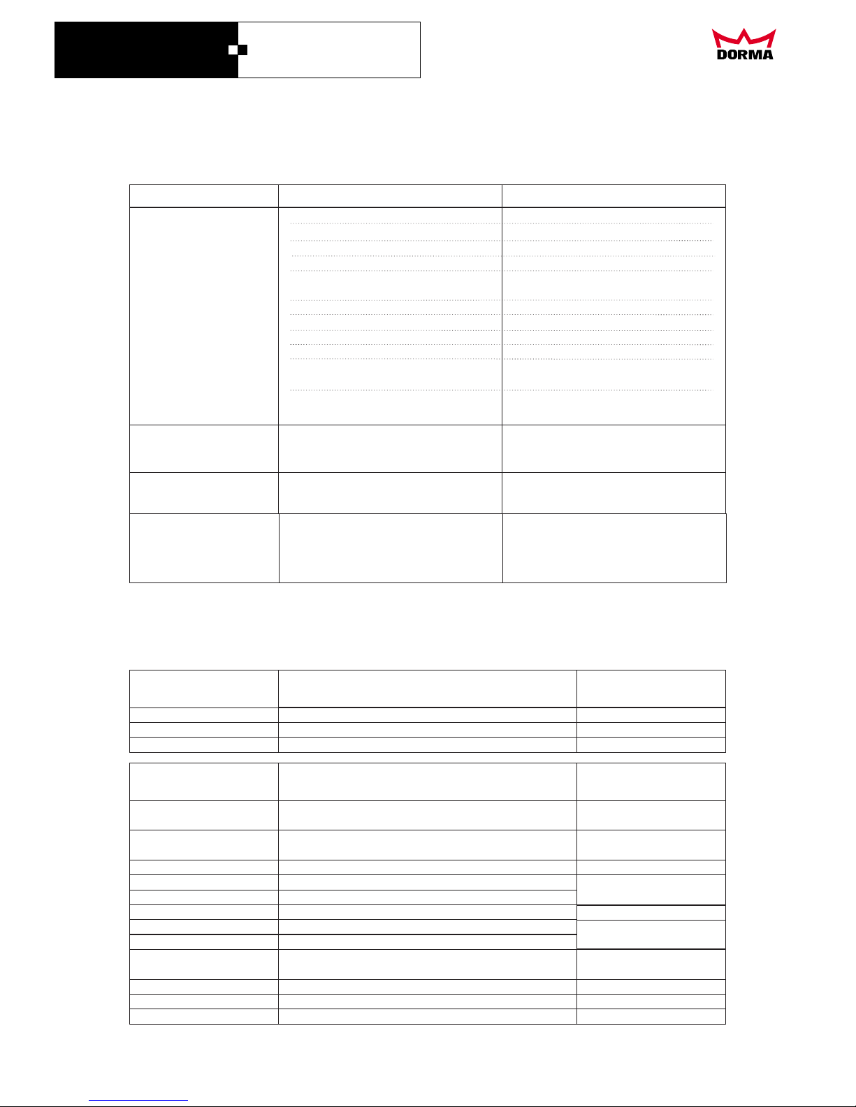
7. Troubleshooting
sesuacelbissoPstluaF
Remedy
The door does not respond.
The door is not operating
in the required mode.
The door is very slow
to move.
The door stops before
reaching the preset opening
angle, and then returns to
its closed position.
No mains power
Valve 3 (Latching action) open too wide.
Bridge (emergency pushbutton) not
positioned.
Program switch set to the
wrong position.
Valve 3 (Latching action) open
too wide.
Wall blanking function incorrectly set.
.
Plug connections not properly inserted.
Defective cabling.
Emergency pushbutton activated.
Program switch in wrong position.
Door obstructed by obstacles.
Door leaf moves only very sluggishly.
Fuse blown.
Radar detector obstructed or lens dirty.
Switch on main power switch.
Insert plugs rmly.
Replace cable.
.
Set program switch to
correct position.
Remove obstructions.
Determine reason and rectify.
Replace fuse
Release emergency pushbutton
.
Clear or clean radar detector.
Slowly close valve 3 until the required
operating behaviour is achieved.
Connect bridge or sensors.
Set program switch to
correct position.
Slowly close valve 3 until the required
operating behaviour is achieved.
Set the angle for the wall blanking
function must always be smaller than
the opening angle).
Adjust safety sensors to optimum position.
(
otoslaehtevahsyawla,noitcessihtgnitlusnocnehW hand.4. Commissioning/5. Adjustments/6. Functional testing section
LED 1 (green)
LED 2 (red) for fault indication by ashing code
- If the system is operating error-free, LED 1 (green) glows continuously.
An error is indicated by a certain ashing sequence (rhythm) performed by LED 2 (red); see following table
Flash codes for fault indication
LED 1 (green) Number
o ashes per sequence
teseRgninaeM
Continuous glow
1
2
4
6
7
9
10
11
13
16
18
Emergency pushbutton
Program switch fault
Incremental encoder fault
Output module fault/Short circuit
EEPROM fault
Sensortest fault
ROM fault, RAM fault, CPU fault
Motor current fault/Motor
Door runtime error
Learning cycle error
Circuit test fault, current measurement
Watchdog test fault
Continuous glow
1
2
Everything OK. Operator is on standby, ready for activation.
Learning cycle has been activated.
Factory default values are being loaded.
-
-
-
Release mergency
Automatic after
fault rectication
Via rogram/main switch
Main switch
Automatic after
Restart earning cycle
Main switch
e
pushbutton
p
Via program/main switch
Main switch
30 s
l
Main switch
Reset
Meaning
LED 2 (red) Number
o ashes per sequence
CD 80
Swing Door Operator
DORMA
11
DORMA AUTOMATICS, Inc. 924 Sherwood Drive Toll-Free: 877-367-6211 DL2862-010
Lake Bluff, IL 60044 Fax: 877-423-7999 Jan. 2007
Page 13
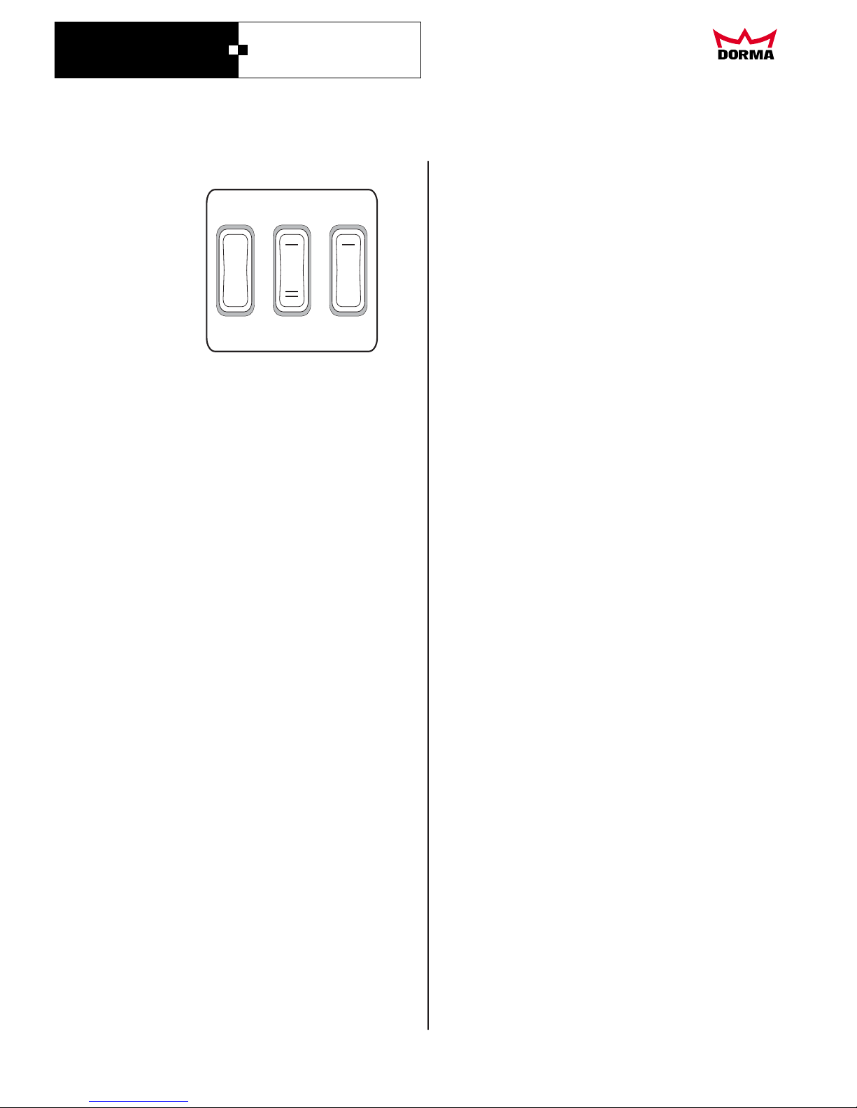
Mains
Program
Extended
hold-open
0
0
8.1 Operator control elements
8.2 Main switch
8.3 Program switch
I = ON
0 = O
The CD 80 can be equipped either with an
internal or an external program switch. Where an
external program switch is installed, the internal
program switch is inoperative.
Both program switches come with the same
functions.
With the program switch in the AUTOMATIC
position, the opening and closing operations are
controlled by the installed activators.
If an opening signal is emitted, the door opens
and then closes automatically on expiry of the
preset hold-open time.
If a further opening signal is triggered during the
hold-open time (with the door in the open
position), the hold-open time is reset to its
original value.
Set the program switch to the PERMANENT
OPEN position. The door will open and then
remain in that position.
Set the program switch from PERMANENT OPEN
to another function (switch position).
The door will close and then continue operating in
the selected mode.
The door may be held at an opening angle of the
extended hold-open function e.g. for the purpose
of room ventilation.
For either 5 or 10 minutes.
- The door travels to the preset partial opening
position where it remains for 5 minutes.
Set the program switch to the PERMANENT
OPEN position.
Press pushbutton once:
- The door opens to the preset
position and remains there until another mode
is selected.
8.3.1 Programm switch functions
I = AUTOMATIC
0 = OFF
II = PERMANENT OPEN
General information on the extended hold-open
function:
with the program
switch set to AUTOMATIC.
with the program switch set to
PERMANENT OPEN.
If the program switch is in the OFF position:
- the electrical functions of the operator have
been shut down;
- all the signal inputs have been disabled.
- the door is locked;
- the operator unit is inoperative.
The door can, however, be manually operated,
either with a lever handle or with a key.
Push&Go function is still in operation.
Press the pushbutton once:
Press the pushbutton twice:
8.3.2 Program switch at OFF:
8.3.3 Program switch at AUTOMATIC:
8.3.4 Program switch at PERMANENT OPEN:
8.3.5 Deactivating the PERMANENT OPEN mode:
In the PERMANENT OPEN mode, the position of the
door is actively monitored. This may result in a slight
movement (self-adjustment) of the door over a small
angular range.
The door can continue to be used in the extended
hold-open mode in the same way as in the
AUTOMATIC mode.
When an activator signal is emitted, the door opens
to its full width and closes on expiry of the preset
hold-open time to the position.
- The door travels to the preset extended hold-open
position and remains there for 10 minutes.
8.4 Extended hold-open function pushbutton
Deactivating the extended opening function with the
program switch set to AUTOMATIC
extended hold-open
In the extended hold-open function, the position of
the door is actively monitored. This can lead to a
slight movement (self-adjustment) of the door within
a small angle range
extended hold-open
extended hold-open
Press the pushbutton for the extended hold-open
function once.
Or, set the program switch from AUTOMATIC to
another mode:
- The door closes and continues operating in the
selected mode.
Extended hold-open
extended hold-open
Extended hold-open function
Extended hold-open
·
·
·
·
8. Operating instructions
CD 80
Swing Door Operator
DORMA
12
DORMA AUTOMATICS, Inc. 924 Sherwood Drive Toll-Free: 877-367-6211 DL2862-010
Lake Bluff, IL 60044 Fax: 877-423-7999 Jan. 2007
Page 14
Deactivating the function in
the PERMANENT OPEN mode.
extended hold-open
··Press the pushbutton for the extended hold-open
function once.
Or, change the program switch from the
PERMANENT OPEN mode to another mode:
- The door closes and then continues to operate in
the selected mode.
- The door will then travel to the preset open
position and automatically close on expiry of the
hold-open time.
- If another opening signal is emitted during the
closing cycle (due to the door being pushed
slightly open again against its closing sweep),
the door will once again return to the preset
open position and close automatically on expiry
of the hold-open time.
If the Push&Go function has been activated, the
Power Assist mode cannot be implemented.
The Push&Go function has priority.
In the parameterisation mode, toggle the Power
Assist function to ON.
This reduces the door closer force.
This reduction in the closer strength means that the
door can be opened manually with greater ease.
The Power Assist mode is subject to speed
limitations. The system is designed in the
AUTOMATIC mode for opening times > 4s.
With the closer forces reduced, the door opens and
closes more slowly in the Power Assist mode alone
(i.e. without manual intervention).
The hold-open time in the Power Assist mode is
generally set at 10 seconds.
The delayed opening for locking mechanism time is
the time lag between the unlocking and the start of
the door opening cycle.
The unlocking time can be set to four dierent
values: 0, 0.3, 0.5 and 0.8 seconds.
This function serves to dampen the door opening
cycle. The angle at which the backcheck function
cuts in can be adjusted in 5 degree increments from
15° to 35°.
The opening cycle up to the full opening width is
then continued at a reduced opening speed.
When closed, the door is always locked.
Each time an activator is operated, the door is
unlocked and opens.
8.5 Push&Go (assisted opening)
8.6 Power Assist mode
8.7 Delayed opening for locking mechanism
8.8 Backcheck
8.9 Emergency pushbutton
8.10 Option: Lock
8.11 Maintenance and care
Ensure that the unit is properly disconnected from
the power source when carrying out cleaning and
maintenance work.
(Guidelines for powered doors, windows and gates,
UL 325)
In the parameterisation mode, toggle the
Push&Go function to ON.
From its closed position, move the door manually
to a few degrees open. This should cause the
opening signal to be triggered:
Press the emergency opushbutton:
- The electrical functions of the operator are
deactivated.
- The operator continues to function as a door
closer.
Release the emergency pushbutton:
- The operator returns to normal operation.
The damping of the opening cycle commences at the
preset backcheck angle.
8. Operating instructions
CD 80
Swing Door Operator
DORMA
13
DORMA AUTOMATICS, Inc. 924 Sherwood Drive Toll-Free: 877-367-6211 DL2862-010
Lake Bluff, IL 60044 Fax: 877-423-7999 Jan. 2007
Page 15
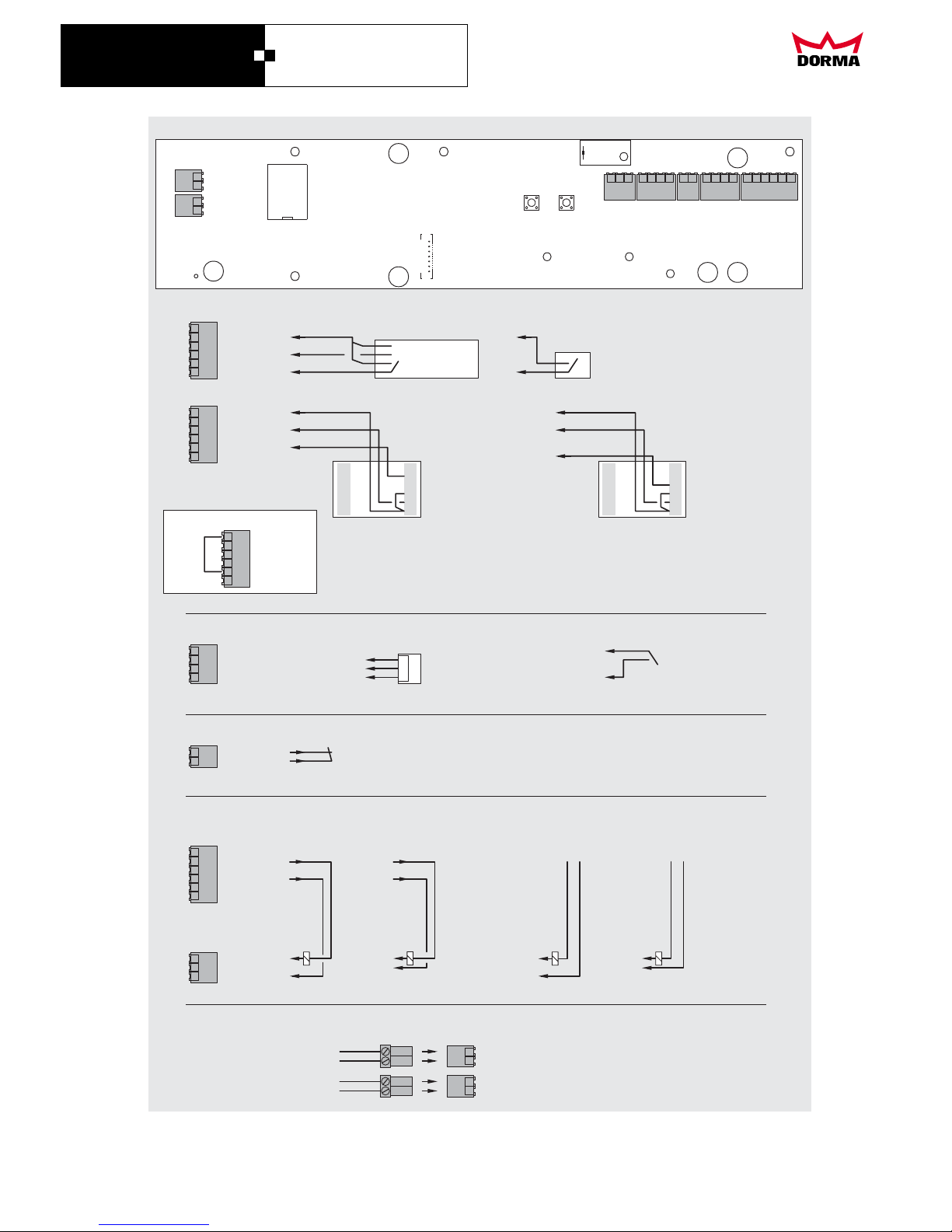
9
8
13
10
11
12
1
3
4
-
+
3
4
-
+
1
2
+
-
+
-
10 3
-7 6
11 2+
+8
5
12 1-
9 4
10 3
-7 6
11 2+
+8
5
12 1-
9 4
+
-
External program switch
3 digit
External switch for
ex. hold-open function
12
13
10
10
Permanent open
Automatic
0 V
11
Emergency OFF
8
9
X6
X3
Internal power supply
e
l
p
i
c
n
i
r
p
e
r
u
c
e
s
l
i
a
F
e
l
p
i
c
n
i
r
p
e
r
u
c
e
s
l
i
a
F
e
l
p
i
c
n
i
r
p
e
f
a
s
-
l
i
a
F
e
l
p
i
c
n
i
r
p
e
f
a
s
-
l
i
a
F
External power supply
7
5
6
5
6
NO
16 16
5
77COM
18 18
677NC
X4
X6
Sensor
Program switch
Emergency pushbutton
Electric strike
Motor, Power supply
X6
Radar
Switch as opening activator
Safety sensor
pull side
Safety sensor
push side
16
17
17
17
+ 24 VDC
+ 24 VDC
+ 24 VDC
14
14
14
19
19
0 V
0 V
0 V
18
18
18
15
Stop
Stop
Stop
8181
15
15
15
0 V
0 V
0 V
4141
19
19
19
14
Start
Start
Start
16
16
16
7171
+ 24 VDC
+ 24 VDC
+ 24 VDC
X5
X2
X1
Power supply
Motor
X6
17
+ 24 VDC
14
0 V
18
Stop
15
0 V
19
Start
16
+ 24 VDC
Without Sensor - set Jumper
CD 80 mit Sensor AIR 16 wiring (Reglomat)
X2
X3 X7
X4
X6
X1
X5X3
T1 T2
CD 80
Swing Door Operator
DORMA
14
DORMA AUTOMATICS, Inc. 924 Sherwood Drive Toll-Free: 877-367-6211 DL2862-010
Lake Bluff, IL 60044 Fax: 877-423-7999 Jan. 2007
 Loading...